


Operating
Instructions
TPS/i Robotics welding system
Pull
PushPull CMT
Operating Instructions
EN
42,0426,0219,EN 024-07032023


Contents
Safety rules 8
Explanation of safety notices 8
General 8
Intended use 9
Environmental conditions 9
Obligations of the operator 9
Obligations of personnel 9
Mains connection 9
Protecting yourself and others 10
Danger from toxic gases and vapours 10
Danger from flying sparks 11
Risks from mains current and welding current 11
Meandering welding currents 13
EMC Device Classifications 13
EMC measures 13
EMF measures 14
Specific hazards 14
Requirement for the shielding gas 15
Danger from shielding gas cylinders 15
Danger from escaping shielding gas 16
Safety measures at the installation location and during transport 16
Safety measures in normal operation 17
Commissioning, maintenance and repair 17
Safety inspection 18
Disposal 18
Safety symbols 18
Data protection 18
Copyright 18
Description of the warning notices on the device 19
EN
System configurations 21
System configurations - conventional robot 23
PowerDrive with wire drum 23
PowerDrive with wire drum and external wirefeeding hose 24
PushPull with 4-roller unreeling wirefeeder and wire drum 25
PushPull with 4-roller unreeling wirefeeder and wirespool 26
PushPull with SB 60i, 4-roller unreeling wirefeeder and wirespool 27
PushPull with 2-roller unreeling wirefeeder, wire drum and external wirefeeding hose 28
CMT with SB 60i, 4-roller unreeling wirefeeder and wire drum 29
CMT with SB 500i, 4-roller unreeling wirefeeder, wire drum and external wirefeeding hose 30
CMT with SB 60i, 4-roller unreeling wirefeeder and wirespool 31
System configurations - PAP 32
PowerDrive with wire drum 32
PushPull with 4-roller unreeling wirefeeder and wire drum 33
PushPull with 4-roller unreeling wirefeeder and wirespool 34
PushPull with 2-roller unreeling wirefeeder and wire drum 35
PushPull with wire buffer, 4-roller unreeling wirefeeder and wire drum 36
PushPull with wire buffer, 4-roller unreeling wirefeeder and wirespool 37
CMT with SB 60i, 4-roller unreeling wirefeeder and wire drum 38
CMT with SB 500i, 4-roller unreeling wirefeeder and wire drum 39
CMT with SB 500i, 4-roller unreeling wirefeeder and wirespool 40
System components 41
SplitBox SB 500i R 43
Device concept 43
Proper use 43
Safety 43
Warning notices on the device 44
3

SplitBox SB 60i R 46
Device concept 46
Proper use 46
Safety 46
Warning notices on the device 47
TPSi wire buffer 49
General 49
CrashBox /i 50
General 50
Note on the correct operation of CrashBoxes 51
Also required for installation 51
Device concept 52
Areas of utilisation 52
Information on repairing CrashBoxes 52
Scope of supply 52
WF Robacta Drive 53
General 53
Warning notices on the device 53
PushPull hosepack 54
General 54
Scope of supply 54
Robot welding torch 55
Safety 55
General 55
WF 25i REEL R /4R, WF 30i REEL R /2R 57
Safety 57
Device concept 57
Application area 57
Proper use 57
Warning notices on the device 58
Interconnecting hosepack 60
General 60
General 60
PowerLiner 61
General 61
WireSense 62
General 62
Requirements 62
How it works 62
WireSense - edge detection 63
WireSense - contour detection 64
Technical details 65
OPT/i camera mount 66
General 66
Drilling template 66
Controls, connections and mechanical components 67
General 69
Safety 69
General 69
SplitBox SB 500i R / SB 500i R PAP 70
Controls, connections, and mechanical components of the SB 500i R 70
Controls, connections, and mechanical components of the SB 500i R PAP 71
SplitBox SB 60i R 73
SB 60i R:Controls, connections, and mechanical components 73
SB 60i R /L:Controls, connections, and mechanical components 74
WF 25i Robacta Drive / WF 60i Robacta Drive CMT 75
Control panel WF 25i Robacta Drive / WF 60i Robacta Drive CMT 75
Status indicators 75
WF 25i REEL R /4R, WF 30i REEL R /2R 77
Control elements, connections and mechanical components 77
Function of the gas-test, wire retract and wire threading buttons 79
4

Function of the gas-test, wire retract and wire threading buttons 79
Assembling system components - conventional robot 81
General 83
Safety 83
Assembly sequence, conventional robot 83
Fitting the SplitBox SB 500i R 84
Fitting the wirefeeder holder 84
Fitting the SB 500i R 84
Fitting the CrashBox /i to the robot 85
Fitting the CrashBox /i to the robot 85
Installing the CrashBox/i Dummy on the robot 86
Fitting the WF Robacta Drive to a conventional robot 88
Fitting the hosepack to the WF Robacta Drive (conventional) 88
Fitting the WF Robacta Drive to the robot (conventional) 89
Fitting the WF Robacta Drive to the robot 90
Optimum hosepack arrangement 91
Fitting the interconnecting hosepack 92
Fitting the Standard interconnecting hosepack to the robot 92
Connecting the MHP W hosepack 93
Connecting the MHP W hosepack 93
Connecting the SplitBox SB 500i R to the system components 96
Safety 96
General 96
Connecting the SplitBox SB 500i R to the system components 96
Assembling system components - PAP robot 99
EN
General 101
Safety 101
Assembly sequence, PAP robot 101
Maximum axis rotation 102
Fitting the SplitBox SB 500i R PAP 103
Fitting the SB 500i R PAP 103
Installing the CrashBox Drive /i PAP on the robot 104
Installing the CrashBox Drive /i PAP on the robot 104
Installing the CrashBox Drive /i PAP Dummy on the robot 105
Fitting the WF Robacta Drive to a PAP robot 107
Fitting the hosepack to the WF Robacta Drive (PAP) 107
Fitting the WF Robacta Drive to the robot (PAP) 108
Fitting the interconnecting hosepack 111
Fitting the PAP interconnecting hosepack to the robot 111
Connecting the SplitBox SB 500i R PAP to the system components 112
Safety 112
General 112
Connecting the SplitBox SB 500i R PAP to the system components 112
Assembling further system components 115
Fitting the SplitBox SB 60i R 117
Fitting the SB 60i R to the robot 117
Fitting the SB 60i R to the balancer 117
Mounting the SB 60i R on the wall 118
Connecting the torch hosepack to the SplitBox SB 60i R 119
Fitting the TPSi wire buffer 120
Fitting the TPSi wire buffer 120
Connecting the control line to the wire buffer 121
Fitting the unreeling wirefeeder 122
Fitting the unreeling wirefeeder 122
Connecting the extension hosepack 123
Connecting the extension hosepack 123
Fitting the torch body to the WF Robacta Drive 125
Fitting the gas-saver nozzle 125
5

Fitting the inner liner inside the torch body 126
Fitting the torch body to the WF Robacta Drive 128
Fitting the OPT/i camera mount 129
Load-bearing capacity of the OPT/i camera mount 129
Safety 129
Fitting the OPT/i camera mount 130
Fitting the inner liner 131
Fitting the inner liner (unreeling wirefeeder - SplitBox SB 500i R) 131
Fitting the inner liner (unreeling wirefeeder- WF Robacta Drive with external wirefeeding
hose)
Fitting the PowerLiner (unreeling wirefeeder - WF Robacta Drive with external wirefeeding hose)
Fitting the inner liner (unreeling wirefeeder - wire buffer) 133
Fitting the inner liner (SplitBox - WF 25i with internal inner liner) 134
Fitting the inner liner (wire buffer - WF Robacta Drive with internal wirefeeding hose) 135
Fitting the inner liner (wire buffer - WF Robacta Drive with external wirefeeding hose) 136
Fitting the inner liner inside the torch hosepack 137
Start-up 139
Inserting/replacing feed rollers 141
General 141
WF 25i Reel 4R: inserting/replacing feed rollers for the 4-roller drive 141
WF 30i Reel 2R: inserting/replacing feed rollers for the 2-roller drive 142
Inserting/replacing the WF 25i Robacta Drive feed rollers 143
Inserting/replacing the WF 60i Robacta Drive CMT feed rollers 145
Feeding in the wire electrode 148
Insulated routing of wire electrode to wirefeeder 148
Feeding in the wire electrode 148
Setting the contact pressure for the WF 25i Robacta Drive 149
Setting the contact pressure for the WF 60i Robacta Drive CMT 150
Start-up 151
Requirements 151
General 151
131
132
Troubleshooting, maintenance and disposal 153
Troubleshooting 155
Safety 155
Fault diagnosis 155
Care, maintenance and disposal 159
General 159
Safety 159
Every start-up 159
Special care of O-rings 159
Whenever the welding torch or torch hosepack is changed 160
Changing the torch hosepack, changing the interconnecting hosepack 160
Every 6 months 160
Recognising faulty wearing parts 161
Replacing the WF 25i Robacta Drive clamping lever 161
Replacing the WF 60i Robacta Drive CMT clamping lever 162
Replacing the WF Robacta Drive gas-saver nozzle 162
Replacing the SB 60i R inner liner 163
Replacing the TPSi wire buffer wire guide 165
Changing the direction of operation of the TPSi wire buffer 166
Replacing the TPSi wire buffer lever 167
Fitting wearing parts to the torch body 168
Fitting wearing parts to the torch body - MTW 700 i 168
Removing the CrashBox PAP from the robot 169
Entsorgung 170
Technical data 171
6

SB 500i R, R left variant, PAP 173
SB 500i R, R left-hand version, PAP 173
SB 60i R 174
SB 60i R 174
CrashBox /i 175
CrashBox /i 175
PushPull hosepack 178
Gas-cooled PushPull hosepacks 178
Water-cooled PushPull hosepacks 179
WF 25i Robacta Drive 181
WF 25i Robacta Drive /G 181
WF 25i Robacta Drive /W 181
WF 60i Robacta Drive CMT 182
WF 60i Robacta Drive CMT /G 182
WF 60i Robacta Drive /W CMT 182
WF 25i REEL R /4R/G/W 184
WF 30i REEL R /2R/G/W 185
Robot welding torch 186
Gas-cooled robot welding torches 186
Water-cooled robot welding torches 187
Interconnecting hosepacks 189
HP 70i 189
HP 95i 189
HP 120i 189
HP 70i, HP PC Cable HD 70 189
EN
7

Safety rules
Explanation of
safety notices
DANGER!
Indicates immediate danger.
If not avoided, death or serious injury will result.
▶
WARNING!
Indicates a potentially hazardous situation.
If not avoided, death or serious injury may result.
▶
CAUTION!
Indicates a situation where damage or injury could occur.
If not avoided, minor injury and/or damage to property may result.
▶
NOTE!
Indicates a risk of flawed results and possible damage to the equipment.
General The device is manufactured using state-of-the-art technology and according to
recognised safety standards. If used incorrectly or misused, however, it can
cause:
injury or death to the operator or a third party,
-
damage to the device and other material assets belonging to the operating
-
company,
inefficient operation of the device.
-
All persons involved in commissioning, operating, maintaining and servicing the
device must:
be suitably qualified,
-
have sufficient knowledge of automated welding, and
-
read and carefully follow these operating instructions as well as the operat-
-
ing instructions for all system components.
The operating instructions must always be at hand wherever the device is being
used. In addition to the operating instructions, attention must also be paid to any
generally applicable and local regulations regarding accident prevention and environmental protection.
All safety and danger notices on the device
must be in a legible state,
-
must not be damaged,
-
must not be removed,
-
must not be covered, pasted or painted over.
-
For the location of the safety and danger notices on the device, refer to the section headed "General" in the operating instructions for the device.
Before commissioning the device, rectify any faults that could compromise
safety.
This is for your personal safety!
8

Intended use The devices and components described in these Operating Instructions are in-
tended exclusively for automated MIG/MAG applications in conjunction with
Fronius components.
Any use above and beyond this purpose is deemed improper. The manufacturer
shall not be held liable for any damage arising from such usage.
Proper use also includes:
Carefully reading and following all the instructions given in the Operating In-
-
structions
Studying and obeying all safety instructions and danger notices carefully
-
Performing all stipulated inspection and servicing work
-
The manufacturer likewise accepts no liability for inadequate or incorrect results.
EN
Environmental
conditions
Obligations of
the operator
Operation or storage of the device outside the stipulated area will be deemed as
not in accordance with the intended purpose. The manufacturer shall not be held
liable for any damage arising from such usage.
Ambient temperature range:
during operation: -10 °C to + 40 °C (14 °F to 104 °F)
-
during transport and storage: -20 °C to +55 °C (-4 °F to 131 °F)
-
Relative humidity:
up to 50% at 40 °C (104 °F)
-
up to 90% at 20 °C (68 °F)
-
The surrounding air must be free from dust, acids, corrosive gases or substances,
etc.
Can be used at altitudes of up to 2000 m (6561 ft. 8.16 in.)
The operator must only allow persons to work with the device who:
are familiar with the fundamental instructions regarding safety at work and
-
accident prevention and have been instructed in how to use the device
have read and understood these operating instructions, especially the sec-
-
tion "safety rules", and have confirmed as much with their signatures
are trained to produce the required results.
-
Checks must be carried out at regular intervals to ensure that operators are
working in a safety-conscious manner.
Obligations of
personnel
Mains connection
Before using the device, all persons instructed to do so undertake:
to observe the basic instructions regarding safety at work and accident pre-
-
vention
to read these operating instructions, especially the "Safety rules" section and
-
sign to confirm that they have understood them and will follow them.
Before leaving the workplace, ensure that people or property cannot come to any
harm in your absence.
Devices with a higher rating may affect the energy quality of the mains due to
their current consumption.
9

This may affect a number device types in terms of:
Connection restrictions
-
-
Criteria with regard to the maximum permissible mains impedance
-
Criteria with regard to the minimum short-circuit power requirement
*)
at the interface with the public grid
*)
*)
see "Technical data"
In this case, the plant operator or the person using the device should check
whether the device may be connected, where appropriate by discussing the matter with the power supply company.
IMPORTANT! Ensure that the mains connection is earthed properly
Protecting yourself and others
Anyone working with the device exposes themselves to numerous risks, e.g.
flying sparks and hot pieces of metal
-
Arc radiation, which can damage eyes and skin
-
Hazardous electromagnetic fields, which can endanger the lives of those us-
-
ing cardiac pacemakers
Risk of electrocution from mains current and welding current
-
Greater noise pollution
-
Harmful welding fumes and gases
-
Suitable protective clothing must be worn when working with the device. The
protective clothing must have the following properties:
Flame-resistant
-
Insulating and dry
-
Covers the whole body, is undamaged and in good condition
-
Safety helmet
-
Trousers with no turn-ups
-
Protective clothing refers to a variety of different items. Operators should:
Protect eyes and face from UV rays, heat and sparks using a protective visor
-
and regulation filter
Wear regulation protective goggles with side protection behind the protect-
-
ive visor
Wear stout footwear that provides insulation even in wet conditions
-
Protect the hands with suitable gloves (electrically insulated and providing
-
protection against heat)
Wear ear protection to reduce the harmful effects of noise and to prevent in-
-
jury
Danger from toxic gases and vapours
10
Keep all persons, especially children, out of the working area while any devices
are in operation or welding is in progress. If, however, there are people in the vicinity:
Make them aware of all the dangers (risk of dazzling by the arc, injury from
-
flying sparks, harmful welding fumes, noise, possible risks from mains current and welding current, etc.)
Provide suitable protective equipment
-
Alternatively, erect suitable safety screens/curtains.
-
The fumes produced during welding contain harmful gases and vapours.
Welding fumes contain substances that cause cancer, as stated in Monograph
118 of the International Agency for Research on Cancer.
Use at-source extraction and a room extraction system.
If necessary, use a welding torch with an integrated extraction device.

Keep your face away from welding fumes and gases.
Fumes and hazardous gases
must not be breathed in
-
must be extracted from the working area using appropriate methods.
-
Ensure an adequate supply of fresh air. Ensure that there is a ventilation rate of
at least 20 m³ per hour at all times.
Otherwise, a welding helmet with an air supply must be worn.
If there is any doubt about whether the extraction capacity is sufficient, the
measured toxic emission values should be compared with the permissible limit
values.
The following components are responsible, amongst other things, for the degree
of toxicity of welding fumes:
Metals used for the workpiece
-
Electrodes
-
Coatings
-
Cleaners, degreasers, etc.
-
Welding process used
-
The relevant material safety data sheets and manufacturer's specifications for
the listed components should therefore be studied carefully.
Recommendations for trade fair scenarios, risk management measures and for
identifying working conditions can be found on the European Welding Association website under Health & Safety (https://european-welding.org).
EN
Danger from fly-
ing sparks
Flammable vapours (e.g. solvent fumes) should be kept away from the arc's radiation area.
Close the shielding gas cylinder valve or main gas supply if no welding is taking
place.
Flying sparks may cause fires or explosions.
Never weld close to flammable materials.
Flammable materials must be at least 11 metres (36 ft. 1.07 in.) away from the
arc, or alternatively covered with an approved cover.
A suitable, tested fire extinguisher must be available and ready for use.
Sparks and pieces of hot metal may also get into adjacent areas through small
gaps or openings. Take appropriate precautions to prevent any danger of injury or
fire.
Welding must not be performed in areas that are subject to fire or explosion or
near sealed tanks, vessels or pipes unless these have been prepared in accordance with the relevant national and international standards.
Do not carry out welding on containers that are being or have been used to store
gases, propellants, mineral oils or similar products. Residues pose an explosive
hazard.
Risks from mains
current and
welding current
An electric shock is potentially life threatening and can be fatal.
Do not touch live parts either inside or outside the device.
11

During MIG/MAG welding and TIG welding, the welding wire, the wirespool, the
feed rollers and all pieces of metal that are in contact with the welding wire are
live.
Always set the wirefeeder up on a sufficiently insulated surface or use a suitable,
insulated wirefeeder holder.
Make sure that you and others are protected with an adequately insulated, dry
base or cover for the earth or ground potential. This base or cover must extend
over the entire area between the body and the earth or ground potential.
All cables and leads must be secured, undamaged, insulated and adequately dimensioned. Replace loose connections and scorched, damaged, or inadequately
dimensioned cables and leads immediately.
Use the handle to ensure the power connections are tight before every use.
In the case of power cables with a bayonet connector, rotate the power cable
around the longitudinal axis by at least 180° and pretension.
Do not wrap cables or leads around the body or parts of the body.
The electrode (rod electrode, tungsten electrode, welding wire, etc.) must
never be immersed in liquid for cooling
-
Never touch the electrode when the power source is switched on.
-
Double the open circuit voltage of a power source can occur between the welding
electrodes of two power sources. Touching the potentials of both electrodes at
the same time may be fatal under certain circumstances.
Arrange for the mains cable to be checked regularly by a qualified electrician to
ensure the ground conductor is functioning properly.
Protection class I devices require a mains supply with ground conductor and a
connector system with ground conductor contact for proper operation.
Operation of the device on a mains supply without ground conductor and on a
socket without ground conductor contact is only permitted if all national regulations for protective separation are observed.
Otherwise, this is considered gross negligence. The manufacturer shall not be
held liable for any damage arising from such usage.
If necessary, provide adequate earthing for the workpiece.
Switch off unused devices.
Wear a safety harness if working at height.
Before working on the device, switch it off and pull out the mains plug.
Attach a clearly legible and easy-to-understand warning sign to the device to
prevent anyone from plugging the mains plug back in and switching it on again.
After opening the device:
Discharge all live components
-
Ensure that all components in the device are de-energised.
-
12
If work on live parts is required, appoint a second person to switch off the main
switch at the right moment.

Meandering
welding currents
If the following instructions are ignored, meandering welding currents can develop with the following consequences:
Fire hazard
-
Overheating of parts connected to the workpiece
-
Damage to ground conductors
-
Damage to device and other electrical equipment
-
Ensure that the workpiece is held securely by the workpiece clamp.
Attach the workpiece clamp as close as possible to the area that is to be welded.
Position the device with sufficient insulation against electrically conductive environments, such as insulation against conductive floor or insulation to conductive
racks.
If power distribution boards, twin-head mounts, etc., are being used, note the following: The electrode of the welding torch / electrode holder that is not used is
also live. Make sure that the welding torch / electrode holder that is not used is
kept sufficiently insulated.
In the case of automated MIG/MAG applications, ensure that only an insulated
wire electrode is routed from the welding wire drum, large wirefeeder spool or
wirespool to the wirefeeder.
EN
EMC Device
Classifications
EMC measures In certain cases, even though a device complies with the standard limit values for
Devices in emission class A:
Are only designed for use in industrial settings
-
Can cause line-bound and radiated interference in other areas
-
Devices in emission class B:
Satisfy the emissions criteria for residential and industrial areas. This is also
-
true for residential areas in which the energy is supplied from the public lowvoltage mains.
EMC device classification as per the rating plate or technical data.
emissions, it may affect the application area for which it was designed (e.g. when
there is sensitive equipment at the same location, or if the site where the device
is installed is close to either radio or television receivers).
If this is the case, then the operator is obliged to take appropriate action to rectify the situation.
Check and evaluate the immunity to interference of nearby devices according to
national and international regulations. Examples of equipment that may be susceptible to interference from the device include:
Safety devices
-
Network, signal and data transfer lines
-
IT and telecommunications devices
-
Measuring and calibrating devices
-
Supporting measures for avoidance of EMC problems:
Mains supply
1.
If electromagnetic interference arises despite the correct mains connec-
-
tion, additional measures are necessary (e.g. use of a suitable line filter)
Welding power-leads
2.
must be kept as short as possible
-
must be laid close together (to avoid EMF problems)
-
must be kept well apart from other leads
-
13

Equipotential bonding
3.
Earthing of the workpiece
4.
If necessary, establish an earth connection using suitable capacitors.
-
Shield, if necessary
5.
Shield other devices nearby
-
Shield the entire welding installation
-
EMF measures Electromagnetic fields may pose as yet unknown risks to health:
Effects on the health of persons in the vicinity, e.g. those with pacemakers
-
and hearing aids
Individuals with pacemakers must seek advice from their doctor before ap-
-
proaching the device or any welding that is in progress
For safety reasons, maintain as large a distance as possible between the
-
welding power-leads and the head/torso of the welder
Do not carry welding power-leads and hosepacks over the shoulders or wind
-
them around any part of the body
Specific hazards Keep hands, hair, clothing and tools away from moving parts. For example:
Fans
-
Cogs
-
Rollers
-
Shafts
-
Wirespools and welding wires
-
Do not reach into the rotating cogs of the wire drive or into rotating drive components.
Covers and side panels may only be opened/removed while maintenance or repair
work is being carried out.
During operation
Ensure that all covers are closed and all side panels are fitted properly.
-
Keep all covers and side panels closed.
-
The welding wire emerging from the welding torch poses a high risk of injury
(piercing of the hand, injuries to the face and eyes, etc.).
Therefore, always keep the welding torch away from the body (devices with
wirefeeder) and wear suitable protective goggles.
Never touch the workpiece during or after welding - risk of burns.
Slag can jump off cooling workpieces. The specified protective equipment must
therefore also be worn when reworking workpieces, and steps must be taken to
ensure that other people are also adequately protected.
Welding torches and other parts with a high operating temperature must be allowed to cool down before handling.
Special provisions apply in areas at risk of fire or explosion
- observe relevant national and international regulations.
14
Power sources for work in areas with increased electric risk (e.g. near boilers)
must carry the "Safety" sign. However, the power source must not be located in
such areas.
Risk of scalding from escaping coolant. Switch off cooling unit before disconnecting coolant flow or return lines.

Observe the information on the coolant safety data sheet when handling coolant.
The coolant safety data sheet may be obtained from your service centre or downloaded from the manufacturer's website.
Use only suitable load-carrying equipment supplied by the manufacturer when
transporting devices by crane.
Hook chains or ropes onto all suspension points provided on the load-carry-
-
ing equipment.
Chains and ropes must be at the smallest angle possible to the vertical.
-
Remove gas cylinder and wirefeeder (MIG/MAG and TIG devices).
-
If the wirefeeder is attached to a crane holder during welding, always use a suitable, insulated wirefeeder hoisting attachment (MIG/MAG and TIG devices).
If the device has a carrying strap or handle, this is intended solely for carrying by
hand. The carrying strap is not to be used if transporting with a crane, counterbalanced lift truck or other mechanical hoist.
All lifting tackle (straps, handles, chains, etc.) used in connection with the device
or its components must be tested regularly (e.g. for mechanical damage, corrosion or changes caused by other environmental factors).
The testing interval and scope of testing must comply with applicable national
standards and directives as a minimum.
Odourless and colourless shielding gas may escape unnoticed if an adapter is
used for the shielding gas connection. Prior to assembly, seal the device-side
thread of the adapter for the shielding gas connection using suitable Teflon tape.
EN
Requirement for
the shielding gas
Danger from
shielding gas cylinders
Especially with ring lines, contaminated shielding gas can cause damage to
equipment and reduce welding quality.
Meet the following requirements regarding shielding gas quality:
Solid particle size < 40 µm
-
Pressure condensation point < -20 °C
-
Max. oil content < 25 mg/m³
-
Use filters if necessary.
Shielding gas cylinders contain gas under pressure and can explode if damaged.
As the shielding gas cylinders are part of the welding equipment, they must be
handled with the greatest of care.
Protect shielding gas cylinders containing compressed gas from excessive heat,
mechanical impact, slag, naked flames, sparks and arcs.
Mount the shielding gas cylinders vertically and secure according to instructions
to prevent them falling over.
Keep the shielding gas cylinders well away from any welding or other electrical
circuits.
Never hang a welding torch on a shielding gas cylinder.
Never touch a shielding gas cylinder with an electrode.
Risk of explosion - never attempt to weld a pressurised shielding gas cylinder.
Only use shielding gas cylinders suitable for the application in hand, along with
the correct and appropriate accessories (regulator, hoses and fittings). Only use
shielding gas cylinders and accessories that are in good condition.
15

Turn your face to one side when opening the valve of a shielding gas cylinder.
Close the shielding gas cylinder valve if no welding is taking place.
If the shielding gas cylinder is not connected, leave the valve cap in place on the
cylinder.
The manufacturer's instructions must be observed as well as applicable national
and international regulations for shielding gas cylinders and accessories.
Danger from escaping shielding
gas
Safety measures
at the installation location and
during transport
Risk of suffocation from the uncontrolled escape of shielding gas
Shielding gas is colourless and odourless and, in the event of a leak, can displace
the oxygen in the ambient air.
Ensure an adequate supply of fresh air with a ventilation rate of at least
-
20 m³/hour.
Observe safety and maintenance instructions on the shielding gas cylinder or
-
the main gas supply.
Close the shielding gas cylinder valve or main gas supply if no welding is tak-
-
ing place.
Check the shielding gas cylinder or main gas supply for uncontrolled gas
-
leakage before every start-up.
A device toppling over could easily kill someone. Place the device on a solid, level
surface such that it remains stable
The maximum permissible tilt angle is 10°.
-
Special regulations apply in rooms at risk of fire or explosion
Observe relevant national and international regulations.
-
Use internal directives and checks to ensure that the workplace environment is
always clean and clearly laid out.
Only set up and operate the device in accordance with the degree of protection
shown on the rating plate.
When setting up the device, ensure there is an all-round clearance of 0.5 m (1 ft.
7.69 in.) to ensure that cooling air can flow in and out freely.
When transporting the device, observe the relevant national and local guidelines
and accident prevention regulations. This applies especially to guidelines regarding the risks arising during transport.
Do not lift or transport operational devices. Switch off devices before transport
or lifting.
Before transporting the device, allow coolant to drain completely and detach the
following components:
Wirefeeder
-
Wirespool
-
Shielding gas cylinder
-
After transporting the device, the device must be visually inspected for damage
before commissioning. Any damage must be repaired by trained service technicians before commissioning the device.
16

Safety measures
in normal operation
Only operate the device when all safety devices are fully functional. If the safety
devices are not fully functional, there is a risk of
injury or death to the operator or a third party
-
damage to the device and other material assets belonging to the operator
-
inefficient operation of the device
-
Any safety devices that are not functioning properly must be repaired before
switching on the device.
Never bypass or disable safety devices.
Before switching on the device, ensure that no one is likely to be endangered.
Check the device at least once a week for obvious damage and proper functioning of safety devices.
Always fasten the shielding gas cylinder securely and remove it beforehand if the
device is to be transported by crane.
Only the manufacturer's original coolant is suitable for use with our devices due
to its properties (electrical conductibility, anti-freeze agent, material compatibility, flammability, etc.).
Only use suitable original coolant from the manufacturer.
Do not mix the manufacturer's original coolant with other coolants.
EN
Commissioning,
maintenance and
repair
Only connect the manufacturer's system components to the cooling circuit.
The manufacturer accepts no liability for damage resulting from use of other system components or a different coolant. In addition, all warranty claims will be
forfeited.
Cooling Liquid FCL 10/20 does not ignite. The ethanol-based coolant can ignite
under certain conditions. Transport the coolant only in its original, sealed containers and keep well away from any sources of ignition.
Used coolant must be disposed of properly in accordance with the relevant national and international regulations. The coolant safety data sheet may be obtained from your service centre or downloaded from the manufacturer's website.
Check the coolant level before starting to weld, while the system is still cool.
It is impossible to guarantee that bought-in parts are designed and manufactured to meet the demands made of them, or that they satisfy safety requirements.
Use only original spare and wearing parts (also applies to standard parts).
-
Do not carry out any modifications, alterations, etc. to the device without the
-
manufacturer's consent.
Components that are not in perfect condition must be replaced immediately.
-
When ordering, please give the exact designation and part number as shown
-
in the spare parts list, as well as the serial number of your device.
The housing screws provide the ground conductor connection for earthing the
housing parts.
Only use original housing screws in the correct number and tightened to the specified torque.
17

Safety inspection
Disposal Waste electrical and electronic equipment must be collected separately and re-
The manufacturer recommends that a safety inspection of the device is performed at least once every 12 months.
The manufacturer recommends that the power source be calibrated during the
same 12-month period.
A safety inspection should be carried out by a qualified electrician
after any changes are made
-
after any additional parts are installed, or after any conversions
-
after repair, care and maintenance has been carried out
-
at least every twelve months.
-
For safety inspections, follow the appropriate national and international standards and directives.
Further details on safety inspection and calibration can be obtained from your
service centre. They will provide you on request with any documents you may require.
cycled in an environmentally responsible manner in accordance with the EU Directive and national law. Used equipment must be returned to the distributor or
through a local, authorised collection and disposal system. Proper disposal of the
old device promotes sustainable recycling of material resources. Ignoring this
may lead to potential health/environmental impacts.
Packaging materials
Collected separately. Check your municipality’s regulations. Reduce the volume
of the box.
Safety symbols Devices with the CE mark satisfy the essential requirements of the low-voltage
and electromagnetic compatibility directives (e.g. relevant product standards of
the EN 60 974 series).
Fronius International GmbH hereby declares that the device is compliant with
Directive 2014/53/EU. The full text on the EU Declaration of Conformity can be
found at the following address: http://www.fronius.com
Devices marked with the CSA test mark satisfy the requirements of the relevant
standards for Canada and the USA.
Data protection The user is responsible for the safekeeping of any changes made to the factory
settings. The manufacturer accepts no liability for any deleted personal settings.
Copyright Copyright of these operating instructions remains with the manufacturer.
18
The text and illustrations are all technically correct at the time of printing. We
reserve the right to make changes. The contents of the operating instructions
shall not provide the basis for any claims whatsoever on the part of the purchaser. If you have any suggestions for improvement, or can point out any mistakes that you have found in the instructions, we will be most grateful for your
comments.

Description of
A B
the warning notices on the
device
For certain device versions, warning notices are affixed to the device.
The arrangement of the symbols may vary.
! Warning! Attention!
The symbols represent possible dangers.
A Drive rollers can injure fingers.
B The welding wire and drive parts are live during operation.
Keep hands and metal objects away!
EN
1. An electric shock can be fatal.
1.1 Wear dry, insulating gloves. Do not touch the wire electrode with bare
hands. Do not wear wet or damaged gloves.
1.2 Use a base that is insulated from the floor and work area to protect
against electric shock.
1.3 Before working on the device, switch off the device and pull out the mains
plug or disconnect it from the power supply.
2. Inhalation of welding fumes can be harmful to health.
2.1 Keep your face away from any welding fumes.
19

2.2 Use forced-air ventilation or a local extraction system to remove welding
xx,xxxx,xxxx *
fumes.
2.3 Remove welding fumes with a fan.
3 Welding sparks can cause an explosion or fire.
3.1 Keep flammable materials away from the welding process. Never weld
close to flammable materials.
3.2 Welding sparks can cause a fire. Have fire extinguishers to hand. If neces-
sary, have a supervisor ready who can operate the fire extinguisher.
3.3 Do not weld on drums or closed containers.
4. Arc rays can burn the eyes and injure the skin.
4.1 Wear headgear and protective goggles. Use ear protection and a shirt col-
lar with button. Use a welding helmet with the correct tinting. Wear suitable protective clothing over the entire body.
5. Before working on the system or welding:
undertake training on the device and read the instructions!
6. Do not remove or paint over the warning sticker.
* Manufacturer order number of the sticker
20

System configurations
21

22

System configurations - conventional robot
(6)
(2)
(3)
(9)**
(8)
(4)
(5)
(1)*
(7)*
PowerDrive with
wire drum
(1) Wirefeeding hose with inner liner
(2) TPSi power source
EN
(3) CU cooling unit
(4) Upright console
(5) HP interconnecting hosepack
(6) SplitBox SB 500i R
(7) MHP /i R torch hosepack
(8) WF 25i Robacta Drive
(9) MTB /i R robot welding torch
Maximum wirefeed length:
max. 6 m between wire drum and drive unit
(max. 8 m with PowerLiner)
Possible wire diameters:
0.8 - 1.2 mm
Welding process:
Standard, Pulse, LSC, PMC, PMC-MIX-DRIVE
IMPORTANT! Do not use a wire straightening section or guide roller in this configuration.
* Use the largest inner liner (incl. basic kit)
** Use the inner liner corresponding to the wire diameter (incl. basic kit)
23

PowerDrive with
(6)
(9)**
(8)
(5)
(1)*
(7)*
(2)
(3)
(4)
wire drum and
external
wirefeeding hose
(1) Wirefeeding hose with inner liner
(2) TPSi power source
(3) CU cooling unit
(4) Upright console
(5) HP interconnecting hosepack
(6) SplitBox SB 500i R
(7) MHP /i R welding torch hosepack with external wirefeeding hose
(8) WF 25i Robacta Drive
(9) MTB /i R robot welding torch
Maximum wirefeed length:
max. 6 m between wire drum and drive unit
(max. 8 m with PowerLiner)
Possible wire diameters:
0.8 - 1.2 mm
Welding process:
Standard, Pulse, LSC, PMC, PMC-MIX-DRIVE
IMPORTANT! Do not use a wire straightening section or guide roller in this configuration.
* Use the largest inner liner (incl. basic kit)
** Use the inner liner corresponding to the wire diameter (incl. basic kit)
24

PushPull with 4-
(8)
(11)**
(10)
(1)*
(9)*
(2)
(3)
(1)*
(4)
(5)
(6)
(7)
roller unreeling
wirefeeder and
wire drum
EN
(1) Wirefeeding hose with inner liner
(2) SpeedNet cable COM
(3) Unreeling wirefeeder WF 25i REEL 4R
(4) TPSi power source
(5) CU cooling unit
(6) Upright console
(7) HP interconnecting hosepack
(8) SplitBox SB 500i R
(9) MHP /i R torch hosepack
(10) WF 25i Robacta Drive
(11) MTB /i R robot welding torch
Maximum wirefeed length:
max. 15 m between drive unit and unreeling wirefeeder
-
(max. 20 m with PowerLiner)
max. 8 m between unreeling wirefeeder and wire drum
-
(max. 10 m with PowerLiner)
Minimum length between unreeling wirefeeder and drive unit:
4 m
Possible wire diameters:
0.8 - 2.0 mm
Welding process:
Standard, Pulse, LSC, PMC
* Use the largest inner liner (incl. basic kit)
** Use the inner liner corresponding to the wire diameter (incl. basic kit)
25

PushPull with 4-
(8)
(3)
(4)
(11)**
(10)
(5)
(6)
(1)
(9)*
(2)
(7)*
roller unreeling
wirefeeder and
wirespool
(1) SpeedNet cable COM
(2) Unreeling wirefeeder WF 25i REEL 4R
+ OPT/i WF Reel carriage D300
(3) TPSi power source
(4) CU cooling unit
(5) Upright console
(6) HP interconnecting hosepack
(7) Wirefeeding hose with inner liner
(8) SplitBox SB 500i R
(9) MHP /i R welding torch hosepack with external wirefeeding hose
(10) WF 25i Robacta Drive
(11) MTB /i R robot welding torch
Maximum wirefeed length:
max. 15 m between drive unit and unreeling wirefeeder
(max. 20 m with PowerLiner)
Possible wire diameters:
0.8 - 2.0 mm
Welding process:
Standard, Pulse, LSC, PMC
* Use the largest inner liner (incl. basic kit)
** Use the inner liner corresponding to the wire diameter (incl. basic kit)
26

PushPull with
(10)
(11)**
(9)
(1)
(7)**
(2)
(8)
(3)
(4)
(5)
(6)
SB 60i, 4-roller
unreeling
wirefeeder and
wirespool
EN
(1) SpeedNet cable COM
(2) Unreeling wirefeeder WF 25i REEL 4R
+ OPT/i WF Reel carriage D300
(3) TPSi power source
(4) CU cooling unit
(5) Upright console
(6) HP interconnecting hosepack SB 60i
(7) Wirefeeding hose with inner liner
(8) SplitBox SB 60i R
(9) MHP /i R torch hosepack
(10) WF 25i Robacta Drive
(11) MTB /i R robot welding torch
Maximum wirefeed length:
max. 4 m between drive unit and SB 60i R
-
max. 6 m between SB 60i R and unreeling wirefeeder
-
Minimum length between SB 60i R and drive unit:
1 m
Possible wire diameters:
0.8 - 1.6 mm
Welding processes:
Standard, Pulse, LSC, PMC, PMC-MIX-DRIVE
* Use the largest inner liner (incl. basic kit)
** Use the inner liner corresponding to the wire diameter (incl. basic kit)
27

PushPull with 2-
(9)
(11)**
(8)
(1)
(7)*
(2)
(10)
(3)
(4)
(5)
(6)
roller unreeling
wirefeeder, wire
drum and external wirefeeding hose
(1) Unreeling wirefeeder WF 30i REEL 2R
+ WF Mounting Drum
(2) SpeedNet cable COM
(3) TPSi power source
(4) CU cooling unit
(5) Upright console
(6) HP interconnecting hosepack
(7) Wirefeeding hose with inner liner
(8) SplitBox SB 500i R
(9) MHP /i R welding torch hosepack with external wirefeeding hose
(10) WF 25i Robacta Drive
(11) MHP /i R robot welding torch
Maximum wirefeed length:
max. 8 m between drive unit and unreeling wirefeeder
(max. 10 m with PowerLiner)
Possible wire diameters:
0.8 - 1.6 mm
Welding process:
Standard, Pulse, LSC, PMC, PMC-MIX-DRIVE
IMPORTANT!
This configuration is only possible with wire drum. A wirespool cannot be
-
used.
Do not use a wire straightening section or guide roller in this configuration.
-
* Use the largest inner liner (incl. basic kit)
** Use the inner liner corresponding to the wire diameter (incl. basic kit)
28

CMT with SB 60i,
(9)*
(4)
(5)
(11)**
(8)
(6)
(7)
(1)*
(1)**
(2)
(10)
(3)
(1
(1(1
4-roller unreeling wirefeeder
and wire drum
EN
(1) Wirefeeding hose with inner liner
(2) SpeedNet cable COM
(3) Unreeling wirefeeder WF 25i REEL 4R
(4) TPSi power source
(5) CU cooling unit
(6) Upright console
(7) HP interconnecting hosepack SB 60i
(8) SplitBox SB 60i R
(9) MHP /i R torch hosepack
(10) WF 60i Robacta Drive CMT
(11) MTB /i R robot welding torch
Maximum wirefeed length:
max. 4 m between drive unit and SB 60i R
-
max. 6 m between SB 60i R and unreeling wirefeeder
-
max. 8 m between unreeling wirefeeder and wire drum
-
(max. 10 m with PowerLiner)
Minimum length between wirefeeder and drive unit:
1 m
Possible wire diameters:
0.8 - 1.6 mm aluminium, 0.8 - 1.4 mm steel
Welding process:
Standard, Pulse, LSC, PMC, PMC-MIX-DRIVE, PMC-RIPPLE-DRIVE, CMT
* Use the largest inner liner (incl. basic kit)
** Use the inner liner corresponding to the wire diameter (incl. basic kit)
29

CMT with SB
(9)
(4)
(5)
(12)**
(8)
(6)
(7)
(1)*
(1)**
(2)
(10)*
(3)
(11)
(1
500i, 4-roller unreeling wirefeeder, wire drum and
external
wirefeeding hose
(1) Wirefeeding hose with inner liner
(2) SpeedNet cable COM
(3) Unreeling wirefeeder WF 25i REEL 4R
(4) TPSi power source
(5) CU cooling unit
(6) Upright console
(7) HP interconnecting hosepack
(8) Wire buffer
(9) SplitBox SB 500i R
(10) MHP /i R welding torch hosepack with external wirefeeding hose
(11) WF 60i Robacta Drive CMT
(12) MTB /i R robot welding torch
Maximum wirefeed length:
max. 4 m between drive unit and wire buffer
-
max. 6 m between wire buffer and unreeling wirefeeder
-
max. 8 m between unreeling wirefeeder and wire drum
-
(max. 10 m with PowerLiner)
Minimum length between wirefeeder and drive unit:
1 m
Possible wire diameters:
0.8 - 1.6 mm aluminium, 0.8 - 1.4 mm steel
Welding process:
Standard, Pulse, LSC, PMC, CMT
30
* Use the largest inner liner (incl. basic kit)
** Use the inner liner corresponding to the wire diameter (incl. basic kit)

CMT with SB 60i,
(3)
(4)
(11)**
(8)
(5)
(6)
(1)
(7)**
(2)
(9)*
(2)
(10)
4-roller unreeling wirefeeder
and wirespool
EN
(1) SpeedNet cable COM
(2) Unreeling wirefeeder WF 25i REEL 4R
+ OPT/i WF Reel carriage D300
(3) TPSi power source
(4) CU cooling unit
(5) Upright console
(6) HP interconnecting hosepack SB 60i
(7) Wirefeeding hose with inner liner
(8) SplitBox SB 60i R
(9) MHP /i R torch hosepack
(10) WF 60i Robacta Drive CMT
(11) MTB /i R robot welding torch
Maximum wirefeed length:
max. 4 m between drive unit and SB 60i R
-
max. 6 m between SB 60i R and unreeling wirefeeder
-
Minimum length between wirefeeder and drive unit:
1 m
Possible wire diameters:
0.8 - 1.6 mm aluminium, 0.8 - 1.4 mm steel
Welding processes:
Standard, Pulse, LSC, PMC, CMT
* Use the largest inner liner (incl. basic kit)
** Use the inner liner corresponding to the wire diameter (incl. basic kit)
31

System configurations - PAP
(8)
(2)
(3)
(9)**
(7)*
(1)*
(4)
(6)
(5)
PowerDrive with
wire drum
(1) Wirefeeding hose with inner liner
(2) TPSi power source
(3) CU cooling unit
(4) Upright console
(5) HP interconnecting hosepack
(6) SplitBox SB 500i R
(7) MHP /i R torch hosepack
(8) WF 25i Robacta Drive
(9) MTB /i R robot welding torch
Maximum wirefeed length:
max. 6 m between wire drum and drive unit
(max. 8 m with PowerLiner)
Possible wire diameters:
0.8 - 1.2 mm
Welding process:
Standard, Pulse, LSC, PMC, PMC-MIX-DRIVE
IMPORTANT! Do not use a wire straightening section or guide roller in this configuration.
* Use the largest inner liner (incl. basic kit)
** Use the inner liner corresponding to the wire diameter (incl. basic kit)
32

PushPull with 4-
(8)
(4)
(5)
(11)**
(9)*
(1)*
(6)
(10)
(7)
(2)
(3)
(1)*
(1(1(1
(1(1(1
(1
roller unreeling
wirefeeder and
wire drum
EN
(1) Wirefeeding hose with inner liner
(2) SpeedNet cable COM
(3) Unreeling wirefeeder WF 25i REEL 4R
(4) TPSi power source
(5) CU cooling unit
(6) Upright console
(7) HP interconnecting hosepack
(8) SplitBox SB 500i R
(9) MHP /i R torch hosepack
(10) WF 25i Robacta Drive
(11) MTB /i R robot welding torch
Maximum wirefeed length:
max. 15 m between drive unit and unreeling wirefeeder
-
(max. 20 m with PowerLiner)
max. 8 m between unreeling wirefeeder and wire drum
-
(max. 10 m with PowerLiner)
Minimum length between wirefeeder and drive unit:
4 m
Possible wire diameters:
0.8 - 2.0 mm
Welding process:
Standard, Pulse, LSC, PMC
* Use the largest inner liner (incl. basic kit)
** Use the inner liner corresponding to the wire diameter (incl. basic kit)
33

PushPull with 4-
(8)
(11)**
(9)*
(1)
(10)
(2)
(7)*
(3)
(4)
(5)
(6)
roller unreeling
wirefeeder and
wirespool
(1) SpeedNet cable COM
(2) Unreeling wirefeeder WF 25i REEL 4R
+ OPT/i WF Reel carriage D300
(3) TPSi power source
(4) CU cooling unit
(5) Upright console
(6) HP interconnecting hosepack
(7) Wirefeeding hose with inner liner
(8) SplitBox SB 500i R
(9) MHP /i R torch hosepack
(10) WF 25i Robacta Drive
(11) MTB /i R robot welding torch
Maximum wirefeed length:
max. 15 m between drive unit and unreeling wirefeeder
(max. 20 m with PowerLiner)
Minimum length between wirefeeder and drive unit:
4 m
Possible wire diameters:
0.8 - 2.0 mm
Welding process:
Standard, Pulse, LSC, PMC
34
* Use the largest inner liner (incl. basic kit)
** Use the inner liner corresponding to the wire diameter (incl. basic kit)

PushPull with 2-
(8)
(4)
(5)
(11)**
(9)*
(3)*
(6)
(10)
(7)
(1)
(2)
roller unreeling
wirefeeder and
wire drum
EN
(1) Unreeling wirefeeder WF 30i REEL 2R
+ WF Mounting Drum
(2) SpeedNet cable COM
(3) Wirefeeding hose with inner liner
(4) TPSi power source
(5) CU cooling unit
(6) Upright console
(7) HP interconnecting hosepack
(8) SplitBox SB 500i R
(9) MHP /i R torch hosepack
(10) WF 25i Robacta Drive
(11) MHP /i R robot welding torch
Maximum wirefeed length:
max. 8 m between drive unit and unreeling wirefeeder
(max. 10 m with PowerLiner)
Minimum length between wirefeeder and drive unit:
4 m
Possible wire diameters:
0.8 - 1.6 mm
Welding process:
Standard, Pulse, LSC, PMC, PMC-MIX-DRIVE
IMPORTANT! This configuration is only possible with wire drum. A wirespool
cannot be used.
* Use the largest inner liner (incl. basic kit)
** Use the inner liner corresponding to the wire diameter (incl. basic kit)
35

PushPull with
(8)
(4)
(5)
(12)**
(10)*
(1)*
(6)
(11)
(7)
(2)
(3)
(1)**
(9)
(1)*
wire buffer, 4roller unreeling
wirefeeder and
wire drum
(1) Wirefeeding hose with inner liner
(2) SpeedNet cable COM
(3) Unreeling wirefeeder WF 25i REEL 4R
(4) TPSi power source
(5) CU cooling unit
(6) Upright console
(7) HP interconnecting hosepack
(8) SplitBox SB 500i R
(9) Wire buffer
(10) MHP /i R torch hosepack
(11) WF 25i Robacta Drive
(12) MTB /i R robot welding torch
Maximum wirefeed length:
max. 4 m between drive unit and wire buffer
-
max. 6 m between wire buffer and unreeling wirefeeder
-
max. 8 m between unreeling wirefeeder and wire drum
-
(max. 10 m with PowerLiner)
Possible wire diameters:
0.8 - 2.0 mm aluminium, 0.8 - 1.6 mm steel
Welding process:
Standard, Pulse, LSC, PMC, PMC-MIX-DRIVE
* Use the largest inner liner (incl. basic kit)
** Use the inner liner corresponding to the wire diameter (incl. basic kit)
36

PushPull with
(9)
(12)**
(10)*
(7)**
(8)
(1)
(2)
(7)*
(11)
(3)
(4)
(5)
(6)
wire buffer, 4roller unreeling
wirefeeder and
wirespool
EN
(1) SpeedNet cable COM
(2) Unreeling wirefeeder WF 25i REEL 4R
+ OPT/i WF Reel carriage D300
(3) TPSi power source
(4) CU cooling unit
(5) Upright console
(6) HP interconnecting hosepack
(7) Wirefeeding hose with inner liner
(8) Wire buffer
(9) SplitBox SB 500i R
(10) MHP /i R torch hosepack
(11) WF 25i Robacta Drive
(12) MTB /i R robot welding torch
Maximum wirefeed length:
max. 4 m between drive unit and wire buffer
-
max. 6 m between wire buffer and unreeling wirefeeder
-
Minimum length between wirefeeder and drive unit:
1 m
Possible wire diameters:
0.8 - 1.6 mm
Welding processes:
Standard, Pulse, LSC, PMC, PMC-MIX-DRIVE
* Use the largest inner liner (incl. basic kit)
** Use the inner liner corresponding to the wire diameter (incl. basic kit)
37

CMT with SB 60i,
(8)
(4)
(5)
(11)**
(9)*
(1)**
(6)
(7)
(3)
(2)(1)*
(10)
4-roller unreeling wirefeeder
and wire drum
(1) Wirefeeding hose with inner liner
(2) SpeedNet cable COM
(3) Unreeling wirefeeder WF 25i REEL 4R
(4) TPSi power source
(5) CU cooling unit
(6) Upright console
(7) HP interconnecting hosepack SB 60i
(8) SplitBox SB 60i R
(9) MHP /i R torch hosepack
(10) WF 60i Robacta Drive CMT
(11) MTB /i R robot welding torch
Maximum wirefeed length:
max. 4 m between drive unit and SB 60i R
-
max. 6 m between SB 60i R and unreeling wirefeeder
-
max. 8 m between unreeling wirefeeder and wire drum
-
(max. 10 m with PowerLiner)
Minimum length between wirefeeder and drive unit:
1 m
Possible wire diameters:
0.8 - 1.6 mm aluminium, 0.8 - 1.4 mm steel
38
Welding process:
Standard, Pulse, LSC, PMC, CMT
* Use the largest inner liner (incl. basic kit)
** Use the inner liner corresponding to the wire diameter (incl. basic kit)

CMT with SB
(8)
(12)**
(9)
(10)*
(7)
(3)
(2)(1)*
(11)
(1)**
(1)*
(4)
(5)
(6)
500i, 4-roller unreeling wirefeeder and wire drum
EN
(1) Wirefeeding hose with inner liner
(2) SpeedNet cable COM
(3) Unreeling wirefeeder WF 25i REEL 4R
(4) TPSi power source
(5) CU cooling unit
(6) Upright console
(7) HP interconnecting hosepack
(8) SplitBox SB 500i R
(9) Wire buffer
(10) MHP /i R torch hosepack
(11) WF 60i Robacta Drive CMT
(12) MTB /i R robot welding torch
Maximum wirefeed length:
max. 4 m between drive unit and wire buffer
-
max. 6 m between wire buffer and unreeling wirefeeder
-
max. 8 m between unreeling wirefeeder and wire drum
-
(max. 10 m with PowerLiner)
Minimum length between wirefeeder and drive unit:
1 m
Possible wire diameters:
0.8 - 1.6 mm aluminium, 0.8 - 1.4 mm steel
Welding process:
Standard, Pulse, LSC, PMC, CMT
* Use the largest inner liner (incl. basic kit)
** Use the inner liner corresponding to the wire diameter (incl. basic kit)
39
CMT with SB
(8)
(12)**
(9)
(10)*
(6)
(7)**
(2)
(1)
(11)
(7)*
(3)
(4)
(5)
500i, 4-roller unreeling wirefeeder and wirespool
(1) SpeedNet cable COM
(2) Unreeling wirefeeder WF 25i REEL 4R
+ OPT/i WF Reel carriage D300
(3) TPSi power source
(4) CU cooling unit
(5) Upright console
(6) HP interconnecting hosepack
(7) Wirefeeding hose with inner liner
(8) SplitBox SB 500i R
(9) MHP /i R torch hosepack
(10) WF 60i Robacta Drive CMT
(11) MTB /i R robot welding torch
Maximum wirefeed length:
max. 4 m between drive unit and wire buffer
-
max. 6 m between wire buffer and unreeling wirefeeder
-
Minimum length between wirefeeder and drive unit:
1 m
Possible wire diameters:
0.8 - 1.6 mm aluminium, 0.8 - 1.4 mm steel
Welding processes:
Standard, Pulse, LSC, PMC, CMT
40
* Use the largest inner liner (incl. basic kit)
** Use the inner liner corresponding to the wire diameter (incl. basic kit)

System components
41

42

SplitBox SB 500i R
Device concept The SplitBox (SB) 500i R, SB 500i R / L and SB 500i R PAP devices bring togeth-
er the welding media for automated MIG/MAG welding and have been specially
designed for mounting onto the robot. Two versions of the devices are available:
R = for applications in which the hosepack is externally mounted on the ro-
-
bot
PAP = for applications in which the hosepack is mounted in the robot arm
-
Proper use The device is designed exclusively for bringing together the welding media in
automated MIG/MAG welding applications in conjunction with Fronius system
components. Any use above and beyond this purpose is deemed improper. The
manufacturer shall not be held liable for any damage arising from such usage.
Utilisation in accordance with the intended purpose also comprises:
carefully reading these operating instructions
-
following all the instructions and safety rules in these operating instructions
-
performing all the stipulated inspection and maintenance work
-
EN
Safety
WARNING!
Danger from incorrect operation and work that is not carried out properly.
This can result in serious personal injury and damage to property.
All the work and functions described in this document must only be carried
▶
out by technically trained and qualified personnel.
Read and understand this document in full.
▶
Read and understand all safety rules and user documentation for this device
▶
and all system components.
43

Warning notices
40,0006,3035
Caution:
Attention:
Parts may be at welding
voltage
Les pièces peuvent être
à la tension de soudage
500 A/100% 600 A/60% 650A/40%
I2
0.8 A
I11
U11
60 V
U12 I12 0.5 A24 V
IEC 60 974-1/-10 Cl.A
IP 43
www.fronius.com
Ser.No.:
Part No.:
XXXXXXXXXX
4,040,080
SB 500i R /G/W/FSC
on the device
The device is fitted with safety symbols and a rating plate. The safety symbols
and rating plate must not be removed or painted over. The safety symbols warn
against operating the equipment incorrectly, as this may result in serious injury
and damage.
Welding is dangerous. The following basic requirements must be met to ensure
the equipment is used properly:
Welders must be sufficiently qualified
-
Suitable protective equipment must be used
-
All persons not involved must be kept at a safe distance from the wirefeeder
-
and the welding process
Do not dispose of used devices with domestic waste. Dispose of them according
to the safety rules.
Do not use the functions described here until you have fully read and understood
the following documents:
These Operating Instructions
-
All the Operating Instructions for the system components, especially the
-
safety rules
44

Keep hands, hair, clothing and tools away from moving parts. For example:
Cogs
-
Feed rollers
-
Wirespools and welding wires
-
Do not reach into rotating drive components.
Covers and side panels may only be opened/removed while maintenance or repair
work is being carried out.
During operation
Ensure that all covers are closed and all side panels are fitted properly.
-
Keep all covers and side panels closed.
-
EN
45

SplitBox SB 60i R
Device concept The SB 60i R and SB 60i R /L are devices for bringing together the welding media
in automated MIG/MAG welding and are specially designed for mounting on robots.
SB 60i R:
Right version of the appliance, for fitting to the right side of the robot
SB 60i R /L:
Left version of the appliance, for fitting to the left side of the robot
Proper use The device is designed exclusively for bringing together the welding media in
automated MIG/MAG welding applications in conjunction with Fronius system
components. Any use above and beyond this purpose is deemed improper. The
manufacturer shall not be held liable for any damage arising from such usage.
Utilisation in accordance with the intended purpose also comprises:
carefully reading these operating instructions
-
following all the instructions and safety rules in these operating instructions
-
performing all the stipulated inspection and maintenance work
-
Safety
WARNING!
Danger from incorrect operation and work that is not carried out properly.
This can result in serious personal injury and damage to property.
All the work and functions described in this document must only be carried
▶
out by technically trained and qualified personnel.
Read and understand this document in full.
▶
Read and understand all safety rules and user documentation for this device
▶
and all system components.
46

Warning notices
on the device
The device is fitted with safety symbols and a rating plate. The safety symbols
and rating plate must not be removed or painted over. The safety symbols warn
against operating the equipment incorrectly, as this may result in serious injury
and damage.
EN
Welding is dangerous. The following basic requirements must be met to ensure
the equipment is used properly:
Welders must be sufficiently qualified
-
Suitable protective equipment must be used
-
All persons not involved must be kept at a safe distance from the wirefeeder
-
and the welding process
Do not use the functions described here until you have fully read and understood
the following documents:
These Operating Instructions
-
All the Operating Instructions for the system components, especially the
-
safety rules
47

Do not dispose of used devices with domestic waste. Dispose of them according
to the safety rules.
48

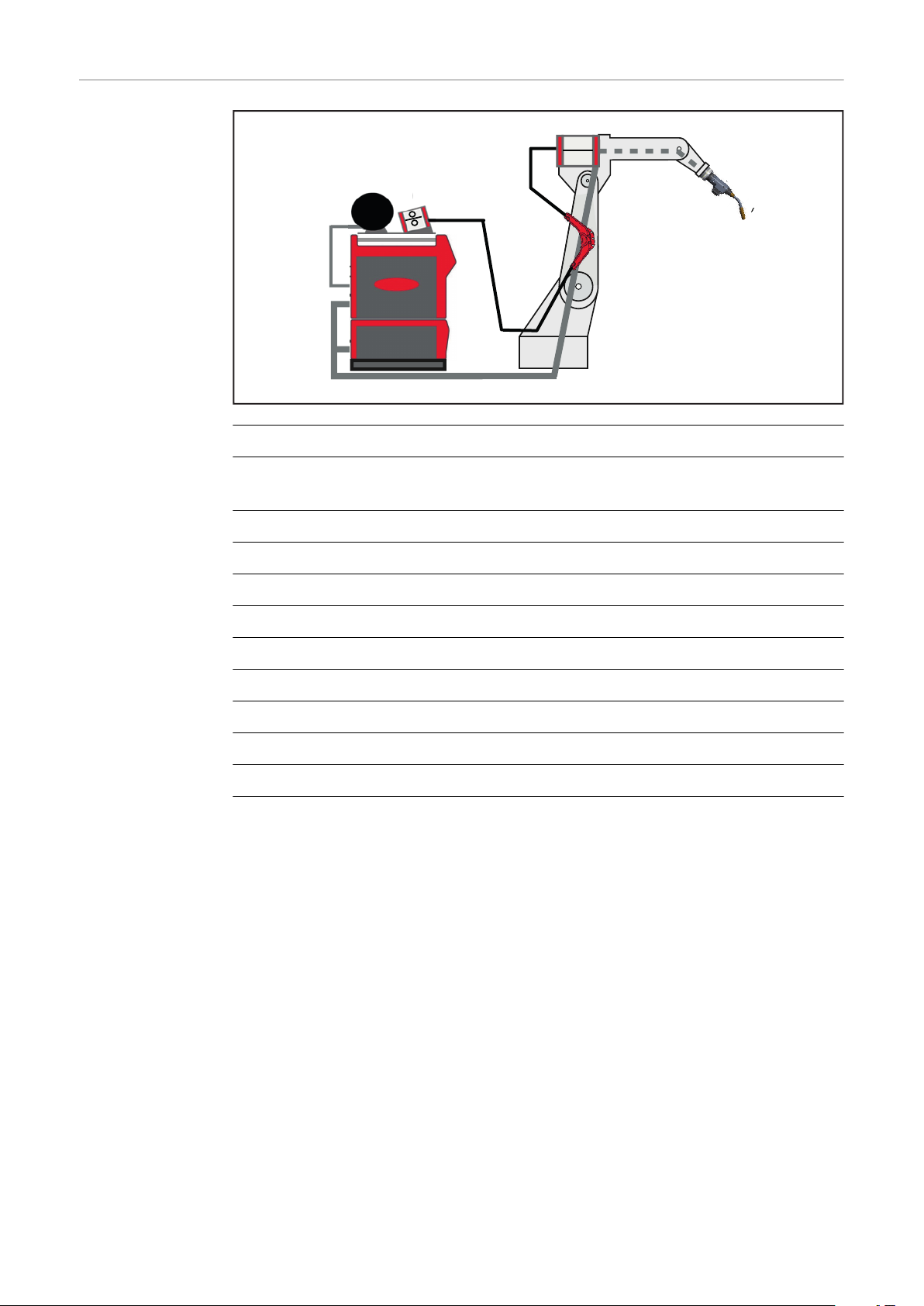
TPSi wire buffer
General As its name implies, the wire buffer
acts as a buffer zone for the rapid reversing movements of the wire electrode needed during the CMT welding
process.
The wire buffer can also be used to
help coordinate two drive systems that
work in different ways. The rear drive
system steadily feeds the wire electrode into the wire buffer, while the
front highly dynamic drive motor
moves it to and fro up to 70 times per
second.
The wire electrode is therefore fed to
the front drive unit with hardly any
force being applied, thus guaranteeing
a high-quality welding process.
EN
The wire buffer is suitable for mounting on the side arm or on the balancer.
49

CrashBox /i
General
A CrashBox Drive /i PAP mounted onto the robot arm with Robacta Drive and MTB
The CrashBox Drive /i is a protection device for the torch body, the drive unit and
the welding torch interchangeable coupling. In the event of a collision, the
CrashBox sends a signal to the robot control, which stops the robot immediately.
The clamp system is used to hold the drive unit on conventional robots.
NOTE!
Always adjust the holding force of the CrashBox to the system weight.
Select the CrashBox size according to the following criteria:
L:
▶
for push systems with a torch body length of up to 249 mm.
XL:
▶
for push systems with a torch body length of up to 249 mm and with extension;
for push systems with a torch body length of 250–391 mm;
for push/pull systems with a torch body length of up to 249 mm.
XXL:
▶
for push/pull systems with a torch body length of 250–391 mm;
for push/pull systems with a torch body length of up to 249 mm and with extension.
If there is a TX/i torch-neck changeover system or WireBrake in the welding
▶
system, select the next larger CrashBox.
When cleaning the welding torch with the TC 2000, also select the next lar-
▶
ger CrashBox.
A CrashBox Drive /i mounted onto the robot arm
with clamp system, Robacta Drive und MTB
50
A robot-specific, isolated robot flange is necessary for fitting the CrashBox
Drive /i.

Note on the correct operation of
CrashBoxes
NOTE!
To avoid damage to the welding torch or the torch hosepack, or to prevent false
triggering of the CrashBox, consider the following points:
Avoid strong accelerations and maximum speeds during robot movements.
▶
Ensure the free movement of the torch hosepack during all robot move-
▶
ments;
The torch hosepack must not tighten in any position and thus exert a strain
on the CrashBox.
The torch hosepack must not whip around or get stuck when moving.
▶
If possible, clarify all movement situations with Fronius system components
▶
in a simulation as early as the concept phase.
EN
Also required for
installation
Depending on the particular robot:
1 x robot flange with screws
-
Robot flange as per price list
Observe torques:
Max. tightening torque for screws of
strength class 8.8
M4 3.3 Nm / 2.43 lb-ft
M5 5.0 Nm / 3.69 lb-ft
M6 6.0 Nm / 4.43 lb-ft
M8 27.3 Nm / 20.14 lb-ft
M10 54 Nm / 39.83 lb-ft
M12 93 Nm / 68.60 lb-ft
51

Device concept The CrashBox Drive /i is designed specifically for fitting to the robot arm and for
(1) (2)(3) (2)(3)(4) (5) (6)
(1) (2) (3) (4) (5)(6)(2)(3)
holding gas-cooled and water-cooled robot hosepacks with robot drive units. For
PAP systems, the torch hosepack runs through the CrashBox and then through
the robot arm. In conventional robot systems the torch hosepack runs along the
robot arm and is attached to the clamp. In the event of a crash, the magnetic
coupling smoothly deflects the forces along a large deflection path.
Areas of utilisation
Information on
repairing CrashBoxes
Scope of supply
The clamp system can be used for the following PushPull robot hosepacks:
MHP /i G/W RD hosepacks
-
NOTE!
Only send complete CrashBoxes for repair!
Incomplete CrashBoxes (e.g. without a magnetic ring) cannot be checked in the
course of a repair.
CrashBox Drive /i PAP scope of supply
(1) CrashBox Drive /i holder
(2) 1-ear clamp *
(3) Locking ring, 2-part *
(4) Bellows
(5) Cheese-head screws, M4 x 16 mm
(6) Magnetic ring
* A two-part locking ring and a 1-ear clamp are supplied fitted to the bel-
Do not fit the CrashBox Drive /i holder (1) and magnetic ring (4) together before
fitting to the robot. The components become even more difficult to release due
to the strong magnetism.
52
Conventional CrashBox /i scope of supply
lows (4).

WF Robacta Drive
General The WF 25i Robacta Drive and WF 60i
Robacta Drive CMT are designed for
gas or water-cooled systems. The builtin motor ensures precise wirefeeding
(pull system). The torch body is fitted
to the Robacta Drive.
EN
Warning notices
on the device
The device is fitted with safety symbols and a rating plate. The safety symbols
and rating plate must not be removed or painted over. The safety symbols warn
against operating the equipment incorrectly, as this may result in serious injury
and damage.
WF 25i Robacta Drive rating plate
Welding is dangerous. The following basic requirements must be met to ensure
the equipment is used properly:
Anyone performing automated welding must be sufficiently qualified
-
Suitable protective equipment must be used
-
All persons not involved must be kept at a safe distance from the wirefeeder
-
and the welding process
WF 60i Robacta Drive CMT rating plate
Do not use the functions described here until you have fully read and understood
the following documents:
These Operating Instructions
-
All the Operating Instructions for the system components, especially the
-
safety rules
53

PushPull hosepack
General The Robacta MHPi RD hosepack is designed for gas-cooled and water-cooled ro-
bot applications. It connects the SplitBox to the wirefeeder.
The length of the hosepack depends on the robot.
The following combinations are available:
Robacta MHPi RD conventional
-
SB500i -> WF 25i Robacta Drive
-
SB60i -> WF 60i Robacta Drive CMT
-
Robacta MHPi RD PAP
-
SB500i -> WF 25i Robacta Drive
-
SB500i -> WF 60i Robacta Drive CMT
-
SB60i -> WF 60i Robacta Drive CMT
-
Robacta MHPi RD conventional with external wirefeeding hose
-
SB500i -> WF 25i Robacta Drive
-
SB500i -> WF 60i Robacta Drive CMT
-
Scope of supply
Robacta MHPi RD conventional hosepack Robacta MHPi RD PAP hosepack
Not supplied:
Inner liners
-
Inlet nozzles
-
Robacta MHPi RD hosepack with external
wirefeeding hose
54

Robot welding torch
Standard OVT TXi TXM OPT CAM*
EN
Safety
Risk of burns from hot torch body, hot torch body coupling and other hot welding torch components.
Before starting work on the torch body, the torch body coupling and all other
welding torch components:
▶
▶
▶
General The following torch bodies are recommended for the CMT process:
-
-
The following maximum angles are permitted during the CMT process:
-
-
CAUTION!
Allow the torch body, torch body coupling and all other welding torch components to cool down to room temperature (+25 °C, +77 °F)
Wear electrically insulated and heat protective gloves
Use a suitable tool
MTB 250i / 320i / 400i / 500i / 700i: 22–36°
MTB 330i: 22°
MTB 250i / 320i / 400i / 500i / 700i: 45°
MTB 330i: 36°
*Optional (no torch body)
The robot welding torch transmits the arc power to the workpiece. The gascooled or water-cooled TPS /i welding torch is designed for use with the CrashBox /i.
The torch body has an integrated lead for gas nozzle touch sensing.
Standard:
With wearing parts, without contact tip
OVT:
Without wearing parts
TXi:
Automatic torch body changeover
TXM:
Manual torch body changeover
55

OPT CAM:
Prepared for the camera recording option
56

WF 25i REEL R /4R, WF 30i REEL R /2R
EN
Safety
Incorrect operation or shoddy workmanship can cause serious injury and damage.
▶
Risk of injury from rotating drive parts if covers are open.
▶
Device concept The unreeling wirefeeder is an extra drive unit for ensuring constant and preci-
sion wirefeeding over large wirefeeding distances between the welding wire drum
and the robot wirefeeder.
While in operation, the unreeling wirefeeder is synchronised with the power
source.
It is supplied with power and controlled by the power source in the welding system.
WARNING!
The following documents must be completely read and understood before
commissioning the unreeling wirefeeder:
these Operating Instructions
the Operating Instructions of the power source in use
the Operating Instructions of all other system components
the safety rules and safety instructions in the above-mentioned documents.
CAUTION!
When performing maintenance or set-up work, make sure that the drive
components of the unreeling wirefeeder cannot be started by the power
source, by a wirefeeder or by any other system add-ons.
The unreeling wirefeeder is available in two versions:
WF 25i REEL R /4R
-
Integrated version with 4-roller drive
WF 30i REEL R /2R
-
Integrated version with 2-roller drive - not permitted in conjunction with a
basket-type spool
Application area All indoor and automated MIG/MAG applications.
Proper use The device is designed exclusively for wirefeeding in automated MIG/MAG weld-
ing applications in conjunction with Fronius system components. Any use above
and beyond this purpose is deemed improper. The manufacturer shall not be
held liable for any damage arising from such usage.
Utilisation in accordance with the intended purpose also comprises:
carefully reading these operating instructions
-
following all the instructions and safety rules in these operating instructions
-
performing all stipulated inspection and maintenance work
-
57

Warning notices
40,0006,3035
on the device
The device is fitted with safety symbols and a rating plate. The safety symbols
and rating plate must not be removed or painted over. The safety symbols warn
against operating the equipment incorrectly, as this may result in serious injury
and damage.
Example: WF 30i REEL R /2R/G/W
Do not dispose of used devices with domestic waste. Dispose of them according
to the safety rules.
Welding is dangerous. The following basic requirements must be met to ensure
the equipment is used properly:
Anyone performing automated welding must be sufficiently qualified
-
Suitable protective equipment must be used
-
All persons not involved must be kept at a safe distance from the wirefeeder
-
and the welding process
58
Do not use the functions described here until you have fully read and understood
the following documents:
These Operating Instructions
-
All the Operating Instructions for the system components, especially the
-
safety rules

Keep hands, hair, clothing and tools away from moving parts. For example:
Cogs
-
Feed rollers
-
Wirespools and welding wires
-
Do not reach into the rotating cogs of the wire drive or into rotating drive components.
Covers and side panels may only be opened / removed while maintenance or repair work is being carried out.
Wear eye protection
EN
59

Interconnecting hosepack
General
The interconnecting hosepack connects the power source to the wirefeeder. With
the TPS/i welding system the interconnecting hosepack is available in two versions - one split and one standard variant.
3 / 5 / 10 / 15 m (extension - split variant)
-
CON hosepacks 4 / 5.5 / 8 / 10 / 15 / 16 m (continuous variant)
-
General
The interconnecting hosepack connects the power source to the SplitBox SB 60i
R.
The interconnecting hosepack is fixed in position on the SplitBox SB 60i R and is
available in the following preconfigured lengths:
3 m (extension - split variant)
-
4 / 6 / 8 m (connection - continuous variant)
-
60

PowerLiner
General
The PowerLiner is a wirefeeder system for all standard wire types. Wire diameters of 0.6 mm to 1.6 mm may be used.
The PowerLiner does not need an inner liner. The wire electrode is guided by
rollers set at an angle of 90 degrees. Seventy-six rollers are used for each metre
of wirefeeding hose. As a result, rolling friction rather than slip friction occurs
during wirefeeding.
EN
The PowerLiner can be made up to any length. For Robacta Drive applications,
lengths of up to 10 m can be realised. For CMT applications, lengths of up to 6 m
can be realised between the unreeling wirefeeder and wire buffer and 4 m
between the wire buffer and drive unit.
A connection can be established to large spool systems, wire drums, welding
torches or wirefeeders using QuickConnect.
Pay attention to the wirefeeding direction when fitting the PowerLiner.
NOTE!
Use of the PowerLiner between the unreeling wirefeeder and SplitBox or
between the unreeling wirefeeder and wire buffer does not produce any advantages in terms of wirefeeding, but is technically feasible.
61

WireSense
General If OPT/i WireSense software activation is available on the power source, the sur-
face, edges and weld seams of a workpiece can be measured with the wire electrode.
The wire electrode functions as a sensor that can precisely scan a component by
means of high-frequency reversing wire movement.
Component geometries are recorded and the position of the individual sheets in
relation to each other is precisely determined.
Advantages:
Quick and easy reaction to real component deviations
-
No re-training - time and cost savings
-
No additional hardware and a cost-effective alternative to laser sensors or
-
other optical measuring systems
No need to calibrate TCP and sensor
-
Robust and compact measuring system without additional space require-
-
ments
Requirements WireSense only works
With automated applications
-
In conjunction with CMT system components WF 60i Robacta Drive CMT,
-
SB 500i R with wire buffer or SB 60i R and WFi Reel.
The CMT Welding Package is not required for the WireSense function.
How it works A sensor voltage with limited current is applied to the wire electrode. If the wire
electrode touches the component, a short circuit is created without welding. The
short circuit is broken again by lifting the wire electrode.
The change in position of the wire electrode up to the short circuit is analysed by
the power source and sent as a height measurement signal to the robot control.
The height measurement signal is compared with the current position data of the
robot control.
If there are differences, the robot can correct the Tool Center Point (TCP) or the
respective coordinate system and compensate component position changes accordingly.
62

WireSense edge detection
The WireSense edge detection is activated and an edge height between 0.5
-
and 20 mm is selected.
The touch signal is output when the defined edge height is detected. In this
-
way the position of the edge can be recorded.
The WireSense Position signal indicates the height of the edge.
-
The air gap detection can also be calculated based on the height value.
-
Signal sequence overview
The robot sets the minimum edge height from which the edge detection is
1.
triggered
(WireSense Edge Detection)
Signal from robot to start or stop WireSense
2.
(WireSense Start)
Signal from the power source for detected short circuit after contact
3.
(ArcStable)
Signal from the power source for the detected edge position
4.
(Touch signal)
Signal from the power source for edge height measurement
5.
(WireSense Position)
EN
NOTE!
Detailed information on the signals can be found in the "Signal descriptions for
TPS/i interface" (42.0426.0227.xx) Operating Instructions.
63

WireSense - contour detection
WireSense contour detection is active when WireSense edge detection =
-
OFF or < 0.5 mm.
The touch signal is not active.
-
The WireSense Position signal provides the actual height values (live values).
-
The additional WireSense Break signal stops the forward movement of the
-
wire electrode and stores the zero reference value
(The zero reference value is useful for overcoming the distance to the component without wirefeeding if the reference value is not set directly on the
component).
Signal sequence overview
For contour detection, WireSense edge detection must be disabled
1.
(WireSense Edge Detection = OFF or < 0.5 mm)
Signal from the robot to start or stop contour detection
2.
(WireSense Start)
Signal from the power source for detected short circuit after contact
3.
(ArcStable)
When contour detection is active, no touch signal is output from the power
4.
source
(no touch signal)
When contour detection is active, the WireSense Position signal always
5.
transmits the current position of the wire electrode (live values)
(WireSense Position)
NOTE!
Detailed information on the signals can be found in the "Signal descriptions for
TPS/i interface" (42.0426.0227.xx) Operating Instructions.
64

Technical details
Edge detection Contour detection
Edge detection and ac-
tual height signal
Height signals
EN
The system outputs a
touch signal when the
edge is detected and
provides the height value
of the detected edge.
Sampling rate approx. 100 Hz approx. 100 Hz
Min. sheet thickness: 0.5 mm -
Max. sheet thickness 20 mm -
Height measurement accuracy
Reproducibility max. +/-0.2 mm
(20 times without weld-
Robot speed 50 cm/min up to 3 m/
recommended: approx.
Recommended sense
time
0.3 mm 0.3 mm
ing)
min
1.5 m/min
The system supplies the
height information as ac-
tual values of the
sampled path.
max. +/-0.2 mm
(20 times without weld-
ing)
- max. 30 s
-
65

OPT/i camera mount
General
Application example of a mounted OPT/i camera mount (44,0350,0080)
The OPT/i camera mount can be used to mount seam tracking systems, cameras
or similar on the robot welding torch.
The camera mount is fitted instead of the torch body union nut; the TCP remains
the same.
The seam tracking system or camera is protected by the CrashBox.
The position of the mounted seam tracking system or camera is reproducible, as
it is positioned with a dowel pin.
Seam tracking system or camera can be mounted in six different places.
The scope of supply of the OPT/i camera mount includes a mounting key (size 60
mm).
Drilling template The following holes are provided as standard on the six surfaces of the OPT/i
camera mount:
4 M4 threaded holes with a depth of 9 mm
-
2 holes Ø 4 mm G7, depth = 6 mm
-
66

Controls, connections and mechan-
ical components
67

68

General
EN
Safety
General
WARNING!
Danger from incorrect operation and work that is not carried out properly.
This can result in serious personal injury and damage to property.
All the work and functions described in this document must only be carried
▶
out by technically trained and qualified personnel.
Read and understand this document in full.
▶
Read and understand all safety rules and user documentation for this device
▶
and all system components.
NOTE!
Depending on the system configuration, either the unreeling wirefeeder or the
robot hosepack drive unit is controlled by the gas-test, wire retract and wire
threading buttons.
69

SplitBox SB 500i R / SB 500i R PAP
(1)(3) (6)
(9) (4)
(7)(8) (5)
(2)(10)
Controls, connections, and
mechanical components of the
SB 500i R
Front of SB 500i R, right-hand version Back of SB 500i R, right-hand version
Front of SB 500i R, left-hand version
No. Function
(1) Dummy cover for option 3
(2) Dummy cover for option 4
(3) Dummy cover for option 1
(4) Welding torch connection
(5) SpeedNet connection
For connecting the SpeedNet cable from the interconnecting hosepack
(6) Dummy cover for option 5
(7) Shielding gas connection
(8) (+) current socket
For connecting the power cable from the interconnecting hosepack
(9) Dummy cover for option 2
(10) Wire infeed tube
Back of SB 500i R, left-hand version
70

No. Function
Controls, connections, and
mechanical components of the
SB 500i R PAP
Side view (right-hand version)
(11) Cover
(12) Feed-through
(13) Operating status LED + gas-
test / wire threading / wire return buttons
(option)
For a functional description of the wire
return, wire threading, and gas-test
buttons, see page 79 onwards.
EN
Front Back
No. Function
(1) (+) current socket
For connecting the power cable from the interconnecting hosepack
(2) Shielding gas connection
(3) SpeedNet connection
For connecting the SpeedNet cable from the interconnecting hosepack
(4) Dummy cover for option 1
(5) Welding torch connection
(6) Dummy cover for option 3
(7) Dummy cover for option 4
(8) Dummy cover for option 5
(9) Dummy cover for option 2
(10) Wire infeed tube
71

Side view
No. Function
(11) Cover
(12) Feed-through
(13) Operating status LED + gas-
test / wire threading / wire return buttons
(option)
For a functional description of the wire
return, wire threading, and gas-test
buttons, see page (→ TARGET NOT
FOUND) onwards.
72

SplitBox SB 60i R
A
B
EN
SB 60i R:
Controls, connections, and
mechanical components
(1) Hole for mounting on the robot
(2) Cover
(3) Hole for mounting on the robot
(4) Dummy cover
or
Operating status LED + gastest / wire threading / wire return buttons
(option)
For a functional description of the wire
return, wire threading, and gas-test
buttons, see page 79 onwards.
Front
(5) Welding torch connection
(6) Coolant hoses to the welding
torch
(7) Dummy cover (SpeedNet or ex-
ternal sensor option)
A - Welding torch side
(8) Wire infeed tube
(via QuickConnect and
wirefeeding hose)
(9) Gas purging 16 bar (option)
(10) Hosepack (fixed)
Gas / water
preconfigured 3 / 4 / 8 m
B - Power source side
73

SB 60i R /L:
A
B
Controls, connections, and
mechanical components
(1) Hole for mounting on the robot
(2) Cover
(3) Hole for mounting on the robot
(4) Dummy cover
or
Operating status LED + gas-
test / wire threading / wire re-
turn buttons
(option)
For a functional description of the wire
return, wire threading, and gas-test
buttons, see page 79 onwards.
Front
(5) Welding torch connection
(6) Coolant hoses to the welding
torch
(7) Dummy cover (SpeedNet or ex-
ternal sensor option)
A - Welding torch side
B - Power source side
(8) Wire infeed tube
(via QuickConnect and
wirefeeding hose)
(9) Gas purging 16 bar (option)
(10) Hosepack (fixed)
Gas / water
preconfigured 3 / 4 / 8 m
74

WF 25i Robacta Drive / WF 60i Robacta Drive
(1) (2)
(4)
(5)
(3)
CMT
Control panel
WF 25i Robacta
Drive / WF 60i
Robacta Drive
CMT
EN
No. Function
(1) Gas-test button*
No. Function
(2) F1 key
No function at present
(3) Wire return button*
(4) Wire threading button*
(5) Display
Status indicator
The status indicators are described in the following section
* For a functional description of the wire return, wire threading, and gas-
test buttons, see page 79 onwards.
Status indicators The following statuses may be indicated on the display of the WF 25i Robacta
Drive / WF 60i Robacta Drive CMT:
Normal operation
Error in
Stop / Robot not ready
Gas testing is active
No connection to the control
Update
75

Teach mode active
Wire threading active
Wire retract active
In applications with a double-head wirefeeder, when process line 1 is
selected.
2 and 3 light up on the other process lines but are smaller in size
In applications with a double-head wirefeeder, when process line 2 is
selected.
1 and 3 light up on the other process lines but are smaller in size
In applications with a double-head wirefeeder, when process line 3 is
selected.
1 and 2 light up on the other process lines but are smaller in size
For applications with WireSwitch, when process line 1 is active
For applications with WireSwitch, when process line 2 is active
76

WF 25i REEL R /4R, WF 30i REEL R /2R
(1)(3) (2)
(1)(5) (4)
(6)(7)
(11) (8)
(9)
(10)
(12)(13)
100 mm
50 mm
4 x M5
3.9 in.
2.0 in.
Control elements, connections and mechanical components
EN
Front of WF 25i REEL R /4R/G/W
Left side
Front of WF 30i REEL R /2R/G/W
Rear
Top/underside
77

No. Function
(1) Cover
(2) Protective cover for the 4-roller drive
(3) 4-roller drive
(4) Protective cover for the 2-roller drive
(5) 2-roller drive
(6) Opening for optional sash lock
(7) Operating status LED + Gas-test / wire threading / wire retract buttons
The function of the wire retract, wire threading and gas-test buttons is described from page 79 onwards.
(8) SpeedNet connection
(9) Blanking cover for optional component
(10) Blanking cover for optional component
(11) Blanking cover for optional component
(12) M20 thread
for connecting QuickConnect option
(13) Wire infeed/outfeed tube
Wire infeed (underside)
Wire outfeed (upper side)
78

Function of the gas-test, wire retract and wire
threading buttons
Function of the
gas-test, wire retract and wire
threading buttons
Operating status LED
Shows steady green when the device is ready for use
Gas-test button
After pressing the gas-test button, gas flows out for 30 seconds. Press the button again to stop the gas flow prematurely.
Wire retract button
The wire electrode can be retracted using one of two methods:
Method 1
Retracting the wire electrode at the preset wire retract speed:
Press and hold the wire retract button
-
The wire electrode will be retracted 1 mm (0.039 in.) after the wire retract
-
button is pressed
After a short pause, the wirefeeder continues to retract the wire electrode. If
-
the wire retract button remains pressed, the speed will increase every
second at a rate of 10 m/min (393.70 ipm) until the preset wire retract speed
is reached
EN
Method 2
Retracting the wire electrode in 1 mm increments (0.039 in. increments)
Do not hold the wire retract button for more than 1 second (tap it)
-
NOTE!
Do not allow long lengths of wire electrode to be retracted, as the wire electrode
is not wound onto the wirespool when retracted.
NOTE!
If there was a ground earth connection with the contact tip before the wire retract button was pressed, the wire electrode will be retracted when the button is
pressed until it is short-circuit-free - it retracts by no more 10 mm (0.39 in.) with
each press of the button.
If the wire electrode still needs to be retracted, press the wire retract button
again.
Wire threading button
Wire threading can be performed using one of two methods:
Method 1
Threading the wire electrode using the preset feeder inching speed:
79

Press and hold the wire threading button
-
The wire electrode will be threaded 1 mm (0.039 in.) after the wire threading
-
button is pressed
After a short pause, the wirefeeder continues to thread the wire electrode. If
-
the wire threading button remains pressed, the speed will increase every
second at a rate of 10 m/min (393.70 ipm) until the preset feeder inching
speed is reached
If the wire electrode comes into contact with a ground earth connection, the
-
wirefeeding will be stopped and the wire electrode will be retracted again by
1 mm (0.039 in.)
Method 2
Threading the wire electrode in 1 mm increments (0.039 in. increments)
Do not press the wire threading button for more than 1 second (tap it)
-
If the wire electrode comes into contact with a ground earth connection, the
-
wirefeeding will be stopped and the wire electrode will be retracted again by
1 mm (0.039 in.)
NOTE!
If there is a ground earth connection with the contact tip before the wire
threading button is pressed, the wire electrode will be retracted when the button is pressed until it is short-circuit-free – it retracts by no more than 10 mm
(0.39 in.) with each press of the button.
If there is still a ground earth connection with the contact tip after 10 mm (0.39
in.) of wire retraction, pressing the wire threading button again will cause the wire
electrode to be retracted again by a maximum of 10 mm (0.39 in.). The process
will be repeated until there is no longer a ground earth connection with the contact tip.
80

Assembling system components -
conventional robot
81

82

General
EN
Safety
WARNING!
Work that is carried out incorrectly can cause serious injury or damage.
The following activities may only be carried out by trained and qualified per-
▶
sonnel.
The Operating Instructions for system components, particularly the chapter
▶
entitled "Safety rules", must be observed.
WARNING!
An electric shock can be fatal.
Before starting the work described below:
Turn the power source mains switch to the "O" position
▶
Disconnect the power source from the mains
▶
Ensure that the power source remains disconnected from the mains until all
▶
work has been completed.
WARNING!
Risk of serious injury and damage from articles being dropped.
For all of the screw connections referred to below:
Check after fitting to ensure they are tight
▶
Check following an unusual operating situation (e.g. crash) to ensure they are
▶
tight
Check regularly to ensure they are tight
▶
Assembly sequence, conventional robot
WARNING!
Danger from electric current due to defective system components and incorrect operation.
This can result in serious personal injury and damage to property.
All cables, leads and hosepacks must always be securely connected, undam-
▶
aged and correctly insulated.
Only use adequately dimensioned cables, leads and hosepacks.
▶
Individual components must be fitted to the robot in the following order:
Robot holder(s) must have already been fitted first
1.
SplitBox
2.
Only for CMT applications and for highly dynamic processes in combination
3.
with a 4-roller unreeling wirefeeder: Wire buffer
CrashBox /i
4.
WF Robacta Drive
5.
Torch hosepack
6.
Interconnecting hosepack
7.
83

Fitting the SplitBox SB 500i R
Fitting the
wirefeeder holder
Fitting the SB
500i R
NOTE!
Depending on the robot, please also note the instructions and information on installing the wirefeeder in the User Information.
1
2 3
84

Fitting the CrashBox /i to the robot
3,3 Nm / 2.43 lb-ft
EN
Fitting the
CrashBox /i to
the robot
1
2 3
Observe the torques when fitting the
robot flange:
Max. tightening torque for screws of
strength class 8.8
M4 3.3 Nm / 2.43 lb-ft
M5 5.0 Nm / 3.69 lb-ft
M6 6.0 Nm / 4.43 lb-ft
M8 27.3 Nm / 20.14 lb-ft
M10 54 Nm / 39.83 lb-ft
M12 93 Nm / 68.60 lb-ft
4 5
85

6 7
8
Installing the
CrashBox/i
Dummy on the
robot
1
Observe the torques when fitting the
robot flange:
Max. tightening torque for screws of
strength class 8.8
M4 3.3 Nm / 2.43 lb-ft
M5 5.0 Nm / 3.69 lb-ft
M6 6.0 Nm / 4.43 lb-ft
M8 27.3 Nm / 20.14 lb-ft
M10 54 Nm / 39.83 lb-ft
M12 93 Nm / 68.60 lb-ft
86

3,3 Nm / 2.43 lb-ft
2
6 Nm / 4.43 lb-ft
3
EN
87

Fitting the WF Robacta Drive to a conventional
42,0411,1315
45,0200,1261
11 Nm / 8.11 lb-ft
robot
Fitting the
hosepack to the
WF Robacta
Drive (conventional)
IMPORTANT! Only fit the drive unit when the power source is switched off.
CAUTION!
Danger of property damage due to dirty or wet coupling point.
Whenever the hosepack is fitted or removed, ensure that the coupling point
▶
is clean and dry.
Remove any coolant that has escaped from the coupling point.
▶
1 2
3
4
88

10 Nm / 7.38 lb-ft
M6 x 12 mm
42 Nm / 30.98 lb-ft
EN
Fitting the WF
Robacta Drive to
the robot (conventional)
1 2
3 4
89

Fitting the WF
42 Nm
30.98 lb-ft
CB
42 Nm
30.98 lb-ft
Robacta Drive to
the robot
1
Mount the index disk 45° from the scope of delivery of the extension
NOTE!
CB (for CrashBox) is stamped on one side of the extension.
This side must be fitted to the index disk that has already been fitted.
▶
2
Fit the extension to the index disc that has
already been fitted in such a way that the
stamped ‘CB’ on the extension points to the index disc!
3
90

Optimum hosep-
R
R
R < 200 mm R ≥ 200 mm
ack arrangement
EN
91

Fitting the interconnecting hosepack
3 Nm
2.21 lb-ft
SB 500i
Fitting the
Standard interconnecting
hosepack to the
robot
1
2
92

Connecting the MHP W hosepack
1
EN
Connecting the
MHP W hosepack
IMPORTANT! Whenever the torch hosepack is fitted or removed, ensure that the
coupling point is clean and dry. Remove any coolant that has escaped from the
coupling point.
1
3
2
4
* Push in hosepack as far as it will go
93

5 6
IMPORTANT! Always route coolant hoses below the hosepack and then guide
them to the connection socket:
WFi R / SB 500i SB 60i
7
94

Disconnecting the coolant hoses
PUSH
1 2
(1) Coolant return (red)
(2) Coolant flow (blue)
EN
IMPORTANT! Connect the coolant
hoses to the cooling unit correctly!
3
95

Connecting the SplitBox SB 500i R to the system
components
Safety
General
WARNING!
An electric shock can be fatal.
Before starting the work described below:
Turn the power source mains switch to the "O" position
▶
Disconnect the power source from the mains
▶
Ensure that the power source remains disconnected from the mains until all
▶
work has been completed
CAUTION!
Risk of injury and damage from loose connections.
All cables, leads and hosepacks must be properly secured, undamaged, insu-
▶
lated and adequately dimensioned.
NOTE!
Also follow the instructions and information in the documents 42,0410,1946
and 42,0410,2010 when connecting the wirefeeder to the system components.
Connecting the
SplitBox SB 500i
R to the system
components
IMPORTANT! Whenever the torch hosepack is fitted or removed, ensure that the
coupling point is clean and dry. Remove any coolant that has escaped from the
coupling point.
1
SB 500i R (right variant)
96

1
2
6
4
5
3
1
SB 500i R (left variant)
2
EN
NOTE!
If present, lead the coolant hoses
from the interconnecting hosepack
under the SB 500i R and connect
them to the torch hosepack.
97

98

Assembling system components -
PAP robot
99

100
 Loading...