

Fronius TPS 2700 MV, TPS 4000 MV, TS 5000 MV, TPS 5000 MV, CMT-A 4000 MV Operation/reference Manual
...Page 1

13 SEP 12
Fronius USA
Fronius USA Fronius USA
Fronius USA
Office: 1-877-376-6487 www.fronius-usa.com
/ Battery Charging Systems / Welding Technology / Solar Electronics
Operations Reference Guide
MIG Welding Equipment
Page 2

Page 3

13 SEP 12
/ Battery Charging Systems / Welding Technology / Solar Electronics
General Information
Table of Contents
Conversion Charts page 1
3d-Drawing page 2
Weld System
Component Layout page 3
Configurations page 4
Power Source
Models page 7
Nameplate page 9
Technical Specifications page 10
Connections and Controls page 11
Wire Feeder
Models page 15
Motor-plate page 17
Connections and Controls page 18
Welding Torch page 22
Cooler page 23
Weld Process
Overview page 24
MIG, short circuit page 26
MIG, pulse page 27
Gas Characteristics page 28
Torch Movement and Position page 32
Discontinuity page 33
Use and Operation
Initial Set-up and Turn-on page 35
Quick Reference Sheet, TPS page 36
Weld Correction Value page 41
Front Panel, TPS page 42
Front Panel, CMT page 45
Quick Reference Sheet, TsT page 55
Front Panel, TsT page 57
Processes
Synergic Lines page 48
Jobs page 49
Resistance Test page 50
Push-Pull Alignment page 51
Cooler Verification page 53
Output Tests page 54
Consumables
Drive Rolls page 61
Liners page 62
Contact Tips page 63
Torch Breakdown page 64
Changing a Liner page 67
Part Numbers page 69
Interface
Models page 76
General Information page 77
Inputs/Outputs page 78
Signal Interaction page 82
Fronius Xplorer page 85
Basic Troubleshooting page 87
Page 4

13 SEP 12
/ Battery Charging Systems / Welding Technology / Solar Electronics
---- 1
1 1
1 ----
General Information
Conversion Charts
Fraction* Decimal* Millimeters Wire Guage**
2/64 .030 0.8 20
- -- .035 0.9 19
- - - .040 1.0 18
3/64 .045 1.2 17
- - - .052 1.4 16
1/16 .062 1.6 14
- - - .071 1.8 13
5/64 .078 2.0 12
3/32 .094 2.4 11
7/64 .109 2.8 9
¼ .250 6.4 2
1/2 .500 12.7 3/4 .750 19.1 -
1 1.00 25.4 -
Meters Feet
0.25 0.8
0.50. 1.6
0.75 2.5
1.00 3.1
1.25 4.1
1.50 4.9
1.75 5.7
2.0 6.6
2.5 8.2
3.0 9.8
3.5 11.5
4.0 13.1
4.5 14.8
5.0 16.4
10 32.8
15 49.2
20 65.6
25 82.0
30 98.4
35 114.8
40 131.2
45 147.6
50 164
55 180.4
60 196.8
65 213.3
70 229.6
75 246.0
Inch/min Mm/sec Cm/min
5 2.12 12.70
10 4.23 25.40
15 6.35 38.10
20 8.47 50.80
25 10.58 63.50
30 12.70 76.20
35 14.82 88.90
40 16.93 101.60
45 19.05 114.30
50 21.17 127.00
55 23.28 139.70
60 25.40 152.40
65 27.51 165.10
70 29.63 177.80
75 31.75 190.50
80 33.86 203.2
85 35.98 215.90
90 38.10 228.60
95 40.21 241.30
100 42.33 254.00
105 44.45 266.70
110 46.56 279.40
115 48.68 292.10
120 50.80 304.80
125 52.91 317.50
130 55.03 330.20
135 57.15 342.90
140 59.26 355.60
145 61.38 368.30
150 63.50 381.00
Conversion Factors
Inch/min to Mm/sec x 0.4233
Inch/min to Cm/min x 2.54
Mm/sec to Inch/min x 2.3622
Cm/min to Inch/min x 0.3937
Ft3/hour to L/min x 0.4719
L/min to Ft3/hour x 2.1189
Meter to Feet x 3.2808
Feet to Meter X 0.3048
Ft3/hour L/min
5 2.36
10 4.72
15 7.08
20 9.44
25 11.80
30 14.16
35 16.52
40 18.88
45 21.24
50 23.60
55 25.95
60 28.31
65 30.67
70 33.03
75 35.39
80 37.75
85 40.11
90 42.47
95 44.83
100 47.19
105 49.55
110 51.91
115 54.27
120 56.63
125 58.99
130 61.35
135 63.71
Page 5

---- 2
2 2
2 ----
Page 6

13 SEP 12
/ Battery Charging Systems / Welding Technology / Solar Electronics
GGGG
HHHH
EEEE
FFFF
DDDD
IIII
JJJJ
FFFF
CCCC
JJJJ
DDDD
DDDD
AAAA
1111
10
1010
10
2222
3333
4444
9999
8888
5555
DDDD
CCCC
7777
DDDD
6666
11
1111
11
BBBB
DDDD
Components consist of
----1111---- Power Source
----2222---- Wire Feeder
----3333---- Torch
----4444---- Work Surface/Fixture
----5555---- Main Power (230 or 460V AC⁄
----6666---- Front Panel
----7777---- Gas Tank
----8888---- Remote Control Unit (RCU⁄
----9999---- Robot Interface
----10
1010
10---- Cooler
----11
1111
11---- PC Interface Tool
Component Layout
Weld System
Component Management
Controlled by LocalNet (Fronius communication
protocol⁄.
Plug and play configuration
Provides both operating power and
communication to peripheral components.
Connections consist of
----AAAA---- Ground Connection
----BBBB---- Main Power (230 or 460V AC⁄
----CCCC---- Gas
----DDDD---- LocalNet
----EEEE---- Motor Voltage (55V DC⁄
----FFFF---- Main Current
----GGGG---- Pump Voltage (230 or 400V AC⁄
----HHHH---- Data Lines (non LocalNet⁄
----IIII---- Coolant Out
----JJJJ---- Coolant In
---- 3
3 3
3 ----
Page 7

13 SEP 12
/ Battery Charging Systems / Welding Technology / Solar Electronics
Weld System
Data
Control Voltages
Welding Current
Coolant Lines
Data
Control Voltages
Welding Current
Shielding Gas
Wire
Coolant Lines
Power
PowerPower
Power----Source Mounted Wire Feeder
Source Mounted Wire FeederSource Mounted Wire Feeder
Source Mounted Wire Feeder
The wire feeder can be mounted directly on top of the welding power
source. This configuration can be applied with either robotic or manual
systems. This configuration allows for the following features.
The connections between the wire feeder to the power source, shielding
gas and coolant are made through the Interconnecting Hose Pack.
The connections between the wire feeder and welder can vary in
length. This allows the operator to relocate the wire feeder if
needed.
Length of the torch and the interconnecting hose pack must be
taken into consideration when determining if the system should be
a push or push/pull orientation.
---- 4
4 4
4 ----
Configurations
Page 8

13 SEP 12
/ Battery Charging Systems / Welding Technology / Solar Electronics
Weld System
Data
Control Voltages
Welding Current
Shielding Gas
Wire
Coolant Lines
Remote Mounted Wire Feeder
Remote Mounted Wire FeederRemote Mounted Wire Feeder
Remote Mounted Wire Feeder
The wire feeder is placed between the welder and the torch location. This placement may or may not be permanent.
This configuration allow for:
Varying distances between the power source and wire feeder.
Enables the wire feeder to torch end distances to be reduced which can reduce the need for a push/pull system.
The wire feeder can be kept within a restricted area while the welder is easily accessible for parameter
monitoring and changes.
Data
Control Voltages
Welding Current
Coolant Lines
---- 5
5 5
5 ----
Configurations
Page 9

13 SEP 12
/ Battery Charging Systems / Welding Technology / Solar Electronics
Weld System
Data
Control Voltages
Welding Current
Shielding Gas
Wire
Coolant Lines
Robot Mounted Wire Feeder
Robot Mounted Wire FeederRobot Mounted Wire Feeder
Robot Mounted Wire Feeder
The wire feeder can be mounted directly to the robot arm or automated system. This type of configuration has no built
in mechanism for manually starting the torch and is intended only for robotic/automated applications.
Interconnecting hose packs can vary in length. The length must be accommodate for the distance between the
power source and feeder but also for the motion of the robot.
This configuration allows for the wire feeder to be kept within a restricted area while the power source is left
accessible area for monitoring and adjusting parameters.
Data
Control Voltages
Welding Current
Coolant Lines
---- 6
6 6
6 ----
Configurations
Page 10

13 SEP 12
/ Battery Charging Systems / Welding Technology / Solar Electronics
Power Source
Trans Synergic (TS) 3200/4000/5000
Three amp ranges available (320, 400, and 500⁄. Multi-voltage model is available
Fully digital, inverter based technology that provides stable, reproducible arc through ENTIRE arc
range.
Welder comes pre-loaded with over 30 standard synergic lines over a large variety of filler metal,
gas types, and wire diameters
Power source is equally suited to robotic, automated, and manual tasks based on application
demands.
Trans-Pulse Synergic (TPS) 3200/4000/5000
Three amp ranges available (320, 400, and 500⁄. Multi-voltage model is available
Welder is capable of pulse welding pre-loaded with pulse-designed synergic lines
Fully digital, inverter based technology that provides stable, reproducible arc through ENTIRE arc
range.
Welder comes pre-loaded with over 50 standard and pulse synergic lines over a large variety of
filler metal, gas types, and wire diameters
Power source is lightweight, easily updateable, and expanded through a plug and
play interface.
---- 7
7 7
7 ----
Models
TPS 2700
270-amp pulse machine with a built in wire feeder. Multi-voltage model is available
Fully digital, inverter based technology that provides stable, reproducible arc through ENTIRE arc
range.
Welder comes pre-loaded with over 50 standard and pulse synergic lines over a large variety of
filler metal, gas types, and wire diameters
Power source is lightweight, easily updateable, and expanded through a plug and play interface.
Page 11

13 SEP 12
/ Battery Charging Systems / Welding Technology / Solar Electronics
Power Source
Trans-Steel (TsT) 3500/5000 Robotic
Two amp ranges available (350 and 500⁄. Multi-voltage model available.
Welder is designed specifically for steel welding, offering a large variety of options at a low price.
Fully digital, inverter based technology that provides stable, reproducible arc through ENTIRE arc
range.
Welder comes pre-loaded with over 30 standard synergic lines over a large variety of filler metal,
gas types, and wire diameters
Designed with robotic or automated welding in mind.
---- 8
8 8
8 ----
Models
Trans-Steel (TsT) 3500/5000 Manual
Two amp ranges available (350 and 500⁄. Multi-voltage model available.
Welder is designed specifically for steel welding, offering a large variety of options at a low price.
Fully digital, inverter based technology that provides stable, reproducible arc through ENTIRE arc
range.
Welder comes pre-loaded with over 30 standard synergic lines over a large variety of filler metal,
gas types, and wire diameters
Trans-Steel (TsT) 3500 Compact
350-amp pulse machine with a built in wire feeder. Multi-voltage model is NOT available
Fully digital, inverter based technology that provides stable, reproducible arc through ENTIRE arc
range.
Welder comes pre-loaded with multiple standard synergic lines over a large variety of filler metal,
gas types, and wire diameters
Power source is lightweight, easily updateable, and expanded through a plug and play interface.
Page 12

13 SEP 12
/ Battery Charging Systems / Welding Technology / Solar Electronics
Power Source
Name Plate
The name plate is found on the top of the
machine just underneath the carrying handle.
This label includes identification, technical,
upgrade, and duty-cycle information about the
welding power supply.
The identification portion of the label will give a detailed
description of the welder, the full part number, and a unique
serial number.
Using the format below, the serial number can be used to
determine the approximate age of the welding power supply.
This technique can be used to age any Fronius product with an
8-digit serial number.
23080753
23 – subtract “11” to get the year of manufacture
08 – this is the week of manufacture (1 – 52)
0753 – this is the item number for the day of manufacture.
---- 9999 ----
The middle portion of the label include technical that includes
duty cycle, amp drops, input and output voltage ranges, and
maximum outputs.
Page 13

13 SEP 12
/ Battery Charging Systems / Welding Technology / Solar Electronics
Power Source
Tech Specs
TPS 2700 MV TPS 3200 MV TS/TPS 4000 MV TS/TPS 5000 MV CMT-A 4000 MV
Mains Voltage Range
3 x 240
3 x 460
200 – 240 V
380 – 460 V
200 – 240 V
380 – 460 V
200 – 240 V
380 – 460 V
200 – 240 V
380 – 460 V
200 – 240 V
380 – 460 V
Mains Tolerance +/-10% +/-10% +/- 10% +/- 10% +/- 10%
Mains Frequency 50 / 60 Hz 50 / 60 Hz 50 / 60 Hz 50 / 60 Hz 50 / 60 Hz
Fuse Protection, slow-blow
3 x 460
3 x 240
25 A
16 A
35 A
35 A
63 A
35 A
63 A
35 A
63 A
35 A
Primary Continuous Current (100% dc) 6.4 – 14.2 A 10.6 – 31.2 A 15.3 – 34.4 A 10.1 – 36.1 A n/a
Primary Continuous Power (100% dc) 4.6 – 10.7 KVA 8.7 – 11.5 kVA 10.6 – 12.4 kVA 12.4 – 13.9 kVA 13.0 –16.0 kVA
Electrical Efficiency 88 – 91% 90 – 91% 88 – 91% 88 – 91% n/a
Welding Current Range
MIG
Stick
TIG
3 – 270 A
10 – 270 A
3 – 270 A
3 – 320 A
10 – 320 A
3 – 320 A
3 – 400 A
10 – 400 A
3 – 400 A
3 – 500 A
10 – 500 A
3 – 500 A
3 – 400 A
10 – 400 A
n/a
Welding Voltage Range
MIG
Stick
TIG
14.2 – 27.5 V
20.4 – 30.8 V
10.1 – 20.8 V
14.2 – 30.0 V
20.4 – 32.8 V
10.1 – 22.8 V
14.2 – 34.0 V
20.4 – 36.0 V
10.1 – 26.0 V
14.2 – 30.0 V
20.4 – 40.0 V
10.1 – 30.0 V
14.2 – 34.0 V
20.4 – 36.0 V
n/a
Max Welding Voltage 34.6 V 49.1 – 63.1 V 48 V 49.2 V n/a
Open Circuit Voltage 50 V 64 – 67 V 68 – 78 V 68 – 78 V 90 V
Duty Cycle 77º F (25º C)
60% @ 270 A
100% @ 210 A
89% @ 320 A
100% @ 304 A
75% @ 400 A
100% @ 365 A
75% @ 500 A
100% @ 450 A
85% @ 400 A
100% @ 380 A
Duty Cycle 104º F (40º C)
60% @ 270 A
100% @ 170 A
40% @ 320 A
60% @ 260 A
100% @ 220 A
40% @ 400 A
60% @ 365 A
100% @ 320 A
40% @ 500 A
60% @ 450 A
100% @ 340 A
40% @ 400 A
60% @ 350 A
100% @ 290 A
---- 10
10 10
10 ----
Page 14
13 SEP 12
/ Battery Charging Systems / Welding Technology / Solar Electronics
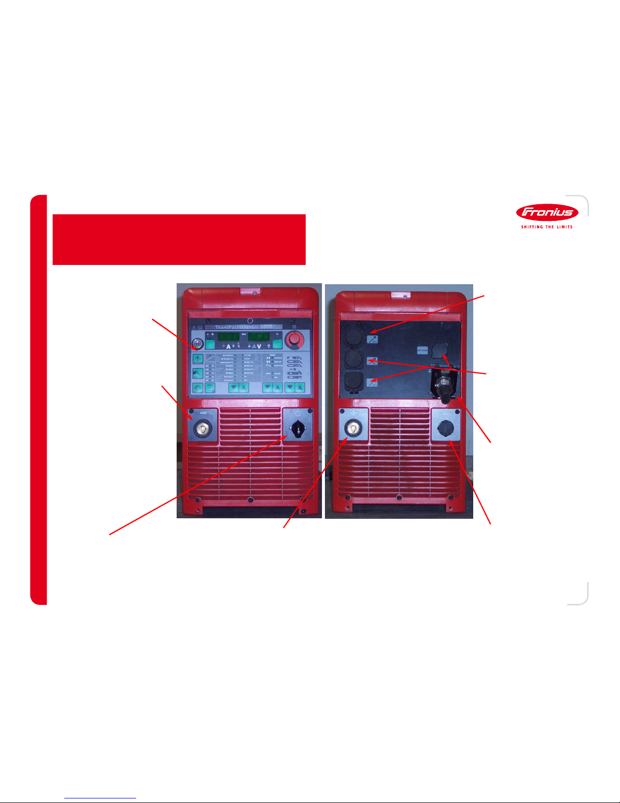
((((----⁄ Current Socket Connection
⁄ Current Socket Connection⁄ Current Socket Connection
⁄ Current Socket Connection
The connection depends on the
operating mode of the power source
MIG Welding
MIG WeldingMIG Welding
MIG Welding: Connect the
welding ground to this socket.
TIG Welding
TIG WeldingTIG Welding
TIG Welding: Connect the
current connection on the torch
to this socket.
STICK Welding
STICK WeldingSTICK Welding
STICK Welding: Connect the
electrode cable to this socket
(depending on the type of
electrode being used⁄.
(+⁄ Current Socket Connection
(+⁄ Current Socket Connection(+⁄ Current Socket Connection
(+⁄ Current Socket Connection
The connection depends on the operating mode of the power source
MIG Welding
MIG WeldingMIG Welding
MIG Welding: Connect the current connection of the interconnection
hose pack to this socket.
TIG Welding
TIG WeldingTIG Welding
TIG Welding: Connect the welding ground to this socket.
STICK Welding
STICK WeldingSTICK Welding
STICK Welding: Connect the electrode cable to this socket (depending
on type of electrode being used⁄.
Power Switch
Power SwitchPower Switch
Power Switch
This switch turns the power source on
(1⁄ and off (0⁄.
Current Connection
Current Connection Current Connection
Current Connection
((((
optional
⁄⁄⁄⁄
This connection is reserved for
an optional current socket
Mains Connection
Mains ConnectionMains Connection
Mains Connection
This connection is for the 3phase input power.
LocalNet Connection
LocalNet ConnectionLocalNet Connection
LocalNet Connection
This connection is for the
LocalNet connection to the wirefeeder and/or interface device.
Blanking Cover(s⁄
Blanking Cover(s⁄Blanking Cover(s⁄
Blanking Cover(s⁄
These connections are for
optional upgrades to the power
source.
Front Panel
Front PanelFront Panel
Front Panel
The front panel allows the welder to
control the power sources welding
characteristics.
Connections – TPS 3200/4000/5000
---- 11
11 11
11 ----
Power Source
Page 15

13 SEP 12
/ Battery Charging Systems / Welding Technology / Solar Electronics
Current Connection
Current ConnectionCurrent Connection
Current Connection
Power Switch
Power SwitchPower Switch
Power Switch
Ground Connection (
Ground Connection (Ground Connection (
Ground Connection (
optional
⁄⁄⁄⁄
Mains Connection
Mains ConnectionMains Connection
Mains Connection
LocalNet Connection
LocalNet ConnectionLocalNet Connection
LocalNet Connection
Blanking Cover(s⁄
Blanking Cover(s⁄Blanking Cover(s⁄
Blanking Cover(s⁄
Front Panel
Front PanelFront Panel
Front Panel
Gas Connection (
Gas Connection (Gas Connection (
Gas Connection (
bottle
⁄⁄⁄⁄
Trigger Connection (
Trigger Connection (Trigger Connection (
Trigger Connection (
torch
⁄⁄⁄⁄
Carrying Strap
Carrying StrapCarrying Strap
Carrying Strap
Current Connection (
Current Connection (Current Connection (
Current Connection (
torch
⁄⁄⁄⁄
Ground Connection
Ground ConnectionGround Connection
Ground Connection
Connections – TPS 2700
---- 12
12 12
12 ----
Power Source
Page 16

13 SEP 12
/ Battery Charging Systems / Welding Technology / Solar Electronics
Current Connection
Current ConnectionCurrent Connection
Current Connection
Ground Connection
Ground ConnectionGround Connection
Ground Connection
Power Switch
Power SwitchPower Switch
Power Switch
Mains Connection
Mains ConnectionMains Connection
Mains Connection
LocalNet Connection
LocalNet ConnectionLocalNet Connection
LocalNet Connection
Optional Add
Optional AddOptional Add
Optional Add----ons
onsons
ons
Front Panel
Front PanelFront Panel
Front Panel
Connections – TsT 3500/5000
Power Source
---- 13
13 13
13 ----
Page 17

13 SEP 12
/ Battery Charging Systems / Welding Technology / Solar Electronics
Current
Current Current
Current
Connection
ConnectionConnection
Connection
Ground
Ground Ground
Ground
Connection
ConnectionConnection
Connection
Power
Power Power
Power
Switch
SwitchSwitch
Switch
Mains
Mains Mains
Mains
Connection
ConnectionConnection
Connection
LocalNet
LocalNet LocalNet
LocalNet
Connection
ConnectionConnection
Connection
Gas Purch / Wire
Gas Purch / Wire Gas Purch / Wire
Gas Purch / Wire
Feed Switch
Feed SwitchFeed Switch
Feed Switch
Front Panel
Front PanelFront Panel
Front Panel
Connections – TsT Compact
Power Source
Gas
Gas Gas
Gas
Connection
ConnectionConnection
Connection
Torch
Torch Torch
Torch
Connector
ConnectorConnector
Connector
---- 14
14 14
14 ----
Page 18

13 SEP 12
/ Battery Charging Systems / Welding Technology / Solar Electronics
Wire Feeder
VR 4000
This wire feeder is designed specifically for manual applications.
This device has the trigger connections required for manual torches to operate.
A removable wire-spool holder is mounted to the rear of the feeder.
Robotic/automated connections and controls can easily be added to this wire feeder
A push/pull torch requires an additional, internally installed kit.
VR 7000 CMT
This wire feeder was developed specifically for the Cold Metal Transfer (CMT⁄ process.
The feeder is equally suited to both manual and robotic/automated needs.
A wire spool holder is integrated to the feeder allowing for both spool and drum use.
This feeder is designed to operate with either a push or a push/pull torch.
Models
VR 1500
This wire feeder is designed specifically for robotic or automated applications.
Using this wire feeder for manual welding is not feasible without special
modifications
A push/pull torch requires an additional, internally installed kit.
---- 15
15 15
15 ----
VR 1550
This wire feeder is designed specifically for robotic or automated applications.
Using this wire feeder for manual welding is not feasible without special
modifications
This feeder can be used for CMT and/or push/pull applications using a series of
specially designed kits.
Page 19

13 SEP 12
/ Battery Charging Systems / Welding Technology / Solar Electronics
Wire Feeder
VR 5000 ROB
Newly developed wire feeder specifically designed for the robotic TransSteel Welding
system.
Designed to have the smallest profile of any Fronius wire feeder while maintaining a high
standard of durability and reliability.
Multiple versions available based on the robot type and design (PAP, standard, etc.⁄ with a
large range of options and fixtures to choose from.
---- 16
16 16
16 ----
Models
VR 5000 Manual
Newly developed wire feeder designed specifically for the TransSteel Welding System.
Built with highly reliable, impact resistant materials. This provides reasonable protection
from dragging, dropping and hanging.
Multiple control options to handle both manual and synergic welding needs
Incredibly precise feed system allowing for perfect wire feed
Specialized current connection with data lines integrated to the connection simplifies setup
and keeps wiring to a minimum.
VR 1500 PAP
This wire feeder is designed specifically for robotic through-the-arm applications.
The size and weight was kept as small as possible, keeping only the mandatory components
in the feeder itself and moving the remainder to the welder.
Using this wire feeder for manual welding is not possible.
A push/pull torch requires an additional, internally installed kit.
Page 20

13 SEP 12
/ Battery Charging Systems / Welding Technology / Solar Electronics
Wire Feeder
Fronius Connector (F++⁄
Fronius Connector (F++⁄Fronius Connector (F++⁄
Fronius Connector (F++⁄
Euro Connector (E⁄
Euro Connector (E⁄Euro Connector (E⁄
Euro Connector (E⁄ Tweeco Connector (T⁄
Tweeco Connector (T⁄Tweeco Connector (T⁄
Tweeco Connector (T⁄
Drive Rolls (
Drive Rolls (Drive Rolls (
Drive Rolls (
top
⁄⁄⁄⁄
Drive Rolls (
Drive Rolls (Drive Rolls (
Drive Rolls (
bottom
⁄⁄⁄⁄
Wire Guide Insert (
Wire Guide Insert (Wire Guide Insert (
Wire Guide Insert (
steel or synthetic
⁄⁄⁄⁄
Main Drive Roll
Main Drive RollMain Drive Roll
Main Drive Roll
Torch Connectors
Torch ConnectorsTorch Connectors
Torch Connectors
Tension Knobs
Tension KnobsTension Knobs
Tension Knobs
---- 17
17 17
17 ----
Motor Plate
Fronius System Connector (FSC⁄
Fronius System Connector (FSC⁄Fronius System Connector (FSC⁄
Fronius System Connector (FSC⁄
Page 21

13 SEP 12
/ Battery Charging Systems / Welding Technology / Solar Electronics
Wire Feeder
Connections & Controls – VR 1500
Current Connection (
Current Connection (Current Connection (
Current Connection (
welder
⁄⁄⁄⁄
LocalNet Connection (
LocalNet Connection (LocalNet Connection (
LocalNet Connection (
spare
⁄⁄⁄⁄
LocalNet Connection (
LocalNet Connection (LocalNet Connection (
LocalNet Connection (
welder
⁄⁄⁄⁄
Gas Connection (
Gas Connection (Gas Connection (
Gas Connection (
bottle
⁄⁄⁄⁄
Current/Gas Connection (
Current/Gas Connection (Current/Gas Connection (
Current/Gas Connection (
torch
⁄⁄⁄⁄
Coolant Feed
Coolant Feed Coolant Feed
Coolant Feed ---- hot (
hot (hot (
hot (
torch
⁄⁄⁄⁄
Gas Purge Button
Gas Purge ButtonGas Purge Button
Gas Purge Button
Coolant Feed
Coolant Feed Coolant Feed
Coolant Feed ---- cold (
cold (cold (
cold (
torch
⁄⁄⁄⁄
Wire Inch Button
Wire Inch ButtonWire Inch Button
Wire Inch Button
Robacta Connection (
Robacta Connection (Robacta Connection (
Robacta Connection (
torch
⁄⁄⁄⁄
Coolant Feed
Coolant Feed Coolant Feed
Coolant Feed ---- cold (
cold (cold (
cold (
welder
⁄⁄⁄⁄
Coolant Feed
Coolant Feed Coolant Feed
Coolant Feed ---- hot (
hot (hot (
hot (
welder
⁄⁄⁄⁄
---- 18
18 18
18 ----
Page 22

13 SEP 12
/ Battery Charging Systems / Welding Technology / Solar Electronics
Wire Feeder
Connections & Controls – VR 7000
Gas Purge (
Gas Purge (Gas Purge (
Gas Purge (up⁄ / Wire Feed (
⁄ / Wire Feed (⁄ / Wire Feed (
⁄ / Wire Feed (
down
⁄ switch
⁄ switch⁄ switch
⁄ switch
LHSB Connection (
LHSB Connection (LHSB Connection (
LHSB Connection (
torch
⁄⁄⁄⁄
LocalNet Connection (
LocalNet Connection (LocalNet Connection (
LocalNet Connection (
welder
⁄⁄⁄⁄
Gas Connection (
Gas Connection (Gas Connection (
Gas Connection (
bottle
⁄⁄⁄⁄
Current/Gas Connection (
Current/Gas Connection (Current/Gas Connection (
Current/Gas Connection (
torch
⁄⁄⁄⁄
Coolant Feed
Coolant Feed Coolant Feed
Coolant Feed ---- hot (
hot (hot (
hot (
torch
⁄⁄⁄⁄
Spool Holder
Spool HolderSpool Holder
Spool Holder
Coolant Feed
Coolant Feed Coolant Feed
Coolant Feed ---- cold (
cold (cold (
cold (
torch
⁄⁄⁄⁄
Coolant Feed
Coolant Feed Coolant Feed
Coolant Feed ---- cold (
cold (cold (
cold (
welder
⁄⁄⁄⁄
Coolant Feed
Coolant Feed Coolant Feed
Coolant Feed ---- hot (
hot (hot (
hot (
welder
⁄⁄⁄⁄
LocalNet Connection (
LocalNet Connection (LocalNet Connection (
LocalNet Connection (
spare
⁄⁄⁄⁄
Power Control (
Power Control (Power Control (
Power Control (
WFS, Current, etc.
⁄⁄⁄⁄
Arc Length Control
Arc Length ControlArc Length Control
Arc Length Control
LHSB Connection (
LHSB Connection (LHSB Connection (
LHSB Connection (
welder
⁄⁄⁄⁄
Current Connection (
Current Connection (Current Connection (
Current Connection (
welder
⁄⁄⁄⁄
Trigger Connection (
Trigger Connection (Trigger Connection (
Trigger Connection (
torch
⁄⁄⁄⁄
Buffer Connection (
Buffer Connection (Buffer Connection (
Buffer Connection (
torch
⁄⁄⁄⁄
Robacta Connection (
Robacta Connection (Robacta Connection (
Robacta Connection (
torch
⁄⁄⁄⁄
Motor
MotorMotor
Motor----plate
plateplate
plate
---- 19
19 19
19 ----
Page 23

13 SEP 12
/ Battery Charging Systems / Welding Technology / Solar Electronics
LocalNet Connection (
LocalNet Connection (LocalNet Connection (
LocalNet Connection (
welder
⁄
⁄ ⁄
⁄
PAP System Only -
Current/Gas Connection (
Current/Gas Connection (Current/Gas Connection (
Current/Gas Connection (
torch
⁄⁄⁄⁄
Current Connection (
Current Connection (Current Connection (
Current Connection (
welder
⁄⁄⁄⁄
Motor
MotorMotor
Motor----plate
plateplate
plate
Gas Connection (
Gas Connection (Gas Connection (
Gas Connection (
bottle
⁄
⁄ ⁄
⁄
----
PAP System Only
----
Wire Inch Button
Wire Inch ButtonWire Inch Button
Wire Inch Button
Gas Connection (
Gas Connection (Gas Connection (
Gas Connection (
bottle
⁄
⁄ ⁄
⁄
----
Standard System Only
----
LocalNet Connection (
LocalNet Connection (LocalNet Connection (
LocalNet Connection (
welder
⁄
⁄ ⁄
⁄
Standard System Only -
Wire Inlet (
Wire Inlet (Wire Inlet (
Wire Inlet (
drum or spool
⁄⁄⁄⁄
Wire Feeder
Connections & Controls – VR 5000 Rob
---- 20
20 20
20 ----
Page 24

13 SEP 12
/ Battery Charging Systems / Welding Technology / Solar Electronics
LocalNet Connection (
LocalNet Connection (LocalNet Connection (
LocalNet Connection (
welder
⁄⁄⁄⁄
Gas Connection (
Gas Connection (Gas Connection (
Gas Connection (
bottle
⁄⁄⁄⁄
Current/Gas Connection (
Current/Gas Connection (Current/Gas Connection (
Current/Gas Connection (
torch
⁄⁄⁄⁄
Spool Holder
Spool HolderSpool Holder
Spool Holder
Current Connection (
Current Connection (Current Connection (
Current Connection (
welder
⁄⁄⁄⁄
Motor
MotorMotor
Motor----plate
plateplate
plate
Spool Window
Spool WindowSpool Window
Spool Window
Handle
HandleHandle
Handle
Weld Control
Weld Control Weld Control
Weld Control
Panel
PanelPanel
Panel
Synergic Selection
Synergic Selection Synergic Selection
Synergic Selection
----
Synergic version only
----
Coolant Feed
Coolant Feed Coolant Feed
Coolant Feed ---- cold (
cold (cold (
cold (
torch
⁄
⁄ ⁄
⁄
----
optional add on
----
Coolant Feed
Coolant Feed Coolant Feed
Coolant Feed ---- hot (
hot (hot (
hot (
torch
⁄
⁄ ⁄
⁄
----
optional add on
----
Coolant Feed
Coolant Feed Coolant Feed
Coolant Feed ---- hot (
hot (hot (
hot (
welder
⁄
⁄ ⁄
⁄ ----
optional add on
----
Coolant Feed
Coolant Feed Coolant Feed
Coolant Feed ---- cold (
cold (cold (
cold (
welder
⁄
⁄ ⁄
⁄
----
optional add on
----
Wire Feeder
Connections & Controls – VR 5000 Manual
---- 21
21 21
21 ----
Page 25

13 SEP 12
/ Battery Charging Systems / Welding Technology / Solar Electronics
Manual Torches
Manual TorchesManual Torches
Manual Torches
Trigger to start/stop the arc.
Water-cooled or Air-cooled
Several control options
None
Up/Down (U/D⁄
Jobmaster (JM⁄
Several wire feeder connections
Fronius (F/F++⁄
Fronius System Connector (FSC⁄
Euro (E⁄
Tweeko (Z⁄
Robotic Torches
Robotic TorchesRobotic Torches
Robotic Torches
Robotic/Automated control of the arc
Water-cooled or Air-cooled
No parameter control options.
Wire feed and gas control
Only on drive-based torches.
Several wire feeder connections
Fronius (F/F++⁄
Fronius System Connector (FSC⁄
Euro (E⁄
Tweeko (Z⁄
Will have Robacta in the description
BAAN/Price
BAAN/PriceBAAN/Price
BAAN/Price----book Description Examples
book Description Examplesbook Description Examples
book Description Examples
AL 4000 G/E/UD/4.5m/14.5ft - AL 4000
AL 4000AL 4000
AL 4000 (torch type-manual⁄ GGGG (gas-cooled⁄ EEEE (Euro connector⁄ UD
UDUD
UD (up/down control⁄
Robacta Drive Ext. W/F++/1.75m/5.7ft - Robacta Drive Ext
Robacta Drive ExtRobacta Drive Ext
Robacta Drive Ext (torch type-robotic⁄ WWWW (water-cooled⁄ F++
F++F++
F++ (Fronius connector⁄
PullMig CMT W/F/6m/19.7ft - PullMig CMT
PullMig CMTPullMig CMT
PullMig CMT (torch type-manual⁄ WWWW (water-cooled⁄ FFFF (Fronius connector⁄
Welding Torch
Models
---- 22
22 22
22 ----
Page 26

13 SEP 12
/ Battery Charging Systems / Welding Technology / Solar Electronics
Cooling Units
Cooling UnitsCooling Units
Cooling Units
Standard Features
Standard FeaturesStandard Features
Standard Features
Integrated system linked directly to power source for power and control.
Fuse protection against potential over-voltage damage.
Flow sensor to verify proper coolant movement.
Variable flow measurements to account for lengthy hose-packs.
FK 4000 / FK 5000
FK 4000 / FK 5000FK 4000 / FK 5000
FK 4000 / FK 5000
Standard water cooler for most MIG and TIG packages
Internal reservoir that allows for a completely closed system.
FK 9000
FK 9000FK 9000
FK 9000
High volume water cooler for specialized system that require a larger
coolant capability.
Two separate units with integral components divided between them.
Cooler
Models
---- 23
23 23
23 ----
Page 27

13 SEP 12
/ Battery Charging Systems / Welding Technology / Solar Electronics
---- 24
24 24
24 ----
Weld Process
Overview
Shielded Metal Arc Welding (SMAW)
An arc welding process that produces coalescence of metals by heating them with an arc between a covered metal electrode and the workpiece(s).
Shielding is obtained from decomposition of the electrode covering. Pressure is not used, and filler metal is obtained from the electrode.
– Stick Welding
– Performed with a basic constant current (CC) power source that is equipped with an electrode holder and a ground clamp
– Manual
Gas Tungsten Arc Welding (GTAW)
An arc welding process that produces coalescence of metals by heating them with an arc between a tungsten electrode (non-consumable) and the
workpiece(s). Shielding is obtained from a gas. Pressure may or may not be used, and filler may or may not be used.
– TIG welding
– Performed with a constant current (CC) power source equipped with a GTA welding torch that supplies current through a tungsten electrode
and ground clamp
– GTAW requires an inert gas such as Argon (most commonly used) or Helium (or a mixture of the two) to support the arc
– Manual, Mechanized, and Automated
Gas Metal Arc Welding (GWAW)
An arc welding process that produces coalescence of metals by heating them with an arc between a continuous filler metal electrode and the
workpiece(s). Shielding is obtained entirely from an externally supplied gas.
– MIG/MAG welding
– Performed with a constant voltage (CV) power supply equipped with a wire feeder to supply welding wire through a GMA welding torch to the
workpiece(s) and with a ground clamp to complete the electrical circuit
– Semi–auto process (manual), Mechanized, and Automated
Page 28

13 SEP 12
/ Battery Charging Systems / Welding Technology / Solar Electronics
---- 25
25 25
25 ----
Weld Process
Overview
Synergic Welding
– Computer control of the welding arc based on a single user-defined characteristic (wire-
feed speed, material thickness, amps, etc.)
– Changing the wire-feed speed will automatically adjust the voltage necessary for the
filler metal and gas being used. This is done through the use of a digital signal
processor and a synergic line
– Provides an extremely high level of repeatability and precision
– The synergic line can be modified slightly to account for environmental differences
between laboratory testing and production
Synergic Line
– An arc-characteristic curve that links a number of welding parameters together giving
the most ‘ideal’ values for a specific filler metal, wire diameter, shielding gas, and
operating mode
– This line is created through a complex set of measurements taken while welding with
the specified settings
– A standard line can be chosen/programmed in a matter of seconds with the simple
selection of a few base parameters
TransSynergic and TransPulseSynergic
– Standard MIG power sources available from Fronius
– Both have the ability to do standard (conventional “2 dial”) welding and synergic welding
(one dial)
– The TransPulse Synergic power source has the added ability to perform pulse-synergic
welding
WIRE-FEED SPEED (current)
VOLTAGE
Page 29

13 SEP 12
/ Battery Charging Systems / Welding Technology / Solar Electronics
---- 26
26 26
26 ----
Weld Process
MIG – Short Circuit Transfer
Short Circuit Transfer
This is a transfer mode where the electrode wire touches the work piece “snubbing out” the arc and the heat from electrical resistance violently pinches
off and deposits the molten wire electrode into the weld pool. -The wire heats up forming a ball of metal at the end of the wire which is then reintroduced
into the molten weld pool where it shorts the circuit, then gets pinched off and deposited into the weld pool. The cycle thenrepeats itself.
– Disadvantages include: Limited wire feed speed and therefore lower deposition rates - Cold lapping/lack of fusion is also more likely to occur
(proper technique is needed to avoid cold lapping/lack of fusion) –Moderate amount of spatter (dependent on environmental factors and
parameters).
– Advantages Include: Low heat input -All positions – Gap bridging - Capable Process for thick and thin materials
Globular Transfer:
This is an uncontrolled spray transfer mode. When CO2 or Argon-CO2 is used, a molten ball tends to form on the end of the electrode and may grow in
size until its diameter is greater than the diameter of the electrode. These droplets, larger in size, may cause short circuits and this mode is known as
“globular transfer.” This method of transfer produces a large amount of spatter and higher heat input when compared to the short circuit transfer mode.
– Disadvantages include: High level of spatter and arc instability
– Advantages: Can use 100% CO2 , an inexpensive gas - Has good penetration on thick metals
Spray Transfer:
This is a high heat input transfer mode where the shielding gas is an Argon rich (Argon-Oxygen - 8% Oxygen maximum) or (Argon-CO2 -18% CO2
maximum) mixture. The droplets being sprayed across the arc are very fine and never short circuit the arc therefore propelling small molten droplets of
the electrode across an open arc to the workpiece(s).
– Disadvantages include: High heat input - Limited range of welding positions - Higher percentages of argon required thus increasing gas cost
– Advantages include: High deposition rates - Good penetration - Good weld appearance with little to no spatter
Page 30

13 SEP 12
/ Battery Charging Systems / Welding Technology / Solar Electronics
---- 27
27 27
27 ----
Weld Process
MIG – Pulsed Current Welding (Pulse)
Pulse Welding (GMAW-P):
This is a GMAW process variation in which the welding current is pulsed resulting in a lower heat input for a given set of welding parameters when
compared to conventional GMAW.
– Disadvantages include: Special power source required to support pulsing current - Higher argon percentages required to support arc –
diameter of spatter balls typically larger than conventional GMAW spatter ball size
– Advantages include: High deposition rates - Lower heat inputs - Viable solution to many welding situations - Less spatter when compared to
conventional GMAW – Good weld appearance
Note Concerning Synergic Welding:
Synergic is a term used to describe “single dial” manipulation of multiple welding parameters at the same time.
– Disadvantages include: Specific power source designed to allow single dial manipulation of multiple welding parameters at the same time
– Advantages include: Reduced parameter development time due to the ability to change multiple parameters with a single dial turn (current and
voltage with single dial)
Page 31

13 SEP 12
/ Battery Charging Systems / Welding Technology / Solar Electronics
INERT GASES
INERT GASES INERT GASES
INERT GASES INERT MIXED GASES
INERT MIXED GASESINERT MIXED GASES
INERT MIXED GASES
Argon
Ionizes easily, deep fusion penetration, finger-shaped, low cost to manufacture (filtered out of ambient air⁄.
Helium
Difficult to ionize; high heat conductivity; deep, wide penetration; fluid weld pool; good wetting; more expensive
than argon (filtered out of natural gas⁄
Argon-Helium Mix
The advantages/disadvantage of each gas increases and decreases in relation to the proportion within the mix.
ACTIVE GASES
ACTIVE GASES ACTIVE GASES
ACTIVE GASES ACTIVE MIXED GASES
ACTIVE MIXED GASESACTIVE MIXED GASES
ACTIVE MIXED GASES
CO
2
Reacts with the material, deeper reduced-pore fusion penetration, tends towards spattering, cheap to manufacture
Argon CO2
Combines advantages of its components, the most used gas combination for unalloyed steel and chrome-nickel
Argon Oxygen
Arc more stable, reduced surface tension of weld pool, pore-sensitive, Oxygen 8% maximum
Gas Characteristics
---- 28
28 28
28 ----
Weld Process
Page 32
13 SEP 12
/ Battery Charging Systems / Welding Technology / Solar Electronics
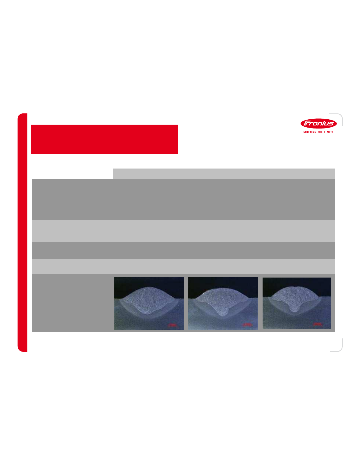
CO
2
Ar/CO
2
Ar/O
2
Fusion Penetration
Horizontal
Positional Welding
Very Good
Very Good
Good
More CO2= better fusion
penetration
Good
Critical
Pores Very Little
Normal
More CO2= fewer pores
Pore-sensitive
Arc Stability Poor, except KL Good Very Good
Spatter Level High Medium Low
Fusion Penetration Profile
---- 29
29 29
29 ----
Weld Process
Overview of Active Mixed Gas
Page 33

13 SEP 12
/ Battery Charging Systems / Welding Technology / Solar Electronics
The proportion of CO2in the gas is mainly responsible for the shape of the arc and the resulting behavior of it (fusion
penetration, pore creation, etc.).
18% CO
2
• Wider arc range
• Wider fusion penetration
• Little pore creation
5% CO
2
• Narrow arc range
• Deeper, narrower fusion
penetration
• Pore creation possible
Impact of CO2on the Arc
---- 30
30 30
30 ----
Weld Process
Page 34

13 SEP 12
/ Battery Charging Systems / Welding Technology / Solar Electronics
Weld Process
Gas Flow
• The flow rate of the shielding gas is a critical aspect of
the welding process. Too high OR too low will have a
serious impact on weld results.
• Rule of thumb for the flow rate: 10 – 12 times the
diameter in l/min of flow
- 1.2mm x 10 = 12 l/min
- 1 l/min = 2.1 CFH
- 12 l/min x 2.1 = 25 CFH
• Helium and Hydrogen require about 50% more flow
than other gases due to their lighter weights.
Correct flow rate
Excessive flow rate
Gas Pressure Sensor (4,100,343)
Manually set gas valve that reports a gas error to the weld
system when flow is too low. Only errors out for low flow
and doesn’t report specific flow information.
Digital Gas Sensor (4,100,374)
The specific gas flow is set, regulated, and monitored
using this device. Not only is a low or high flow rate
detected, but the system also reports back specific gas
flow data.
---- 31
31 31
31 ----
Fronius Options
Typically, the weld system opens and closes the gas
valve. If flow monitoring is desired within the system, the
following options are available.
Page 35

13 SEP 12
/ Battery Charging Systems / Welding Technology / Solar Electronics
Neutral Travel Angle
Arc heats and transmits its total power into the weld pool
Stable, quiet arc
Fusion penetration is
MEDIUM
MEDIUMMEDIUM
MEDIUM
Weld Width is
MEDIUM
MEDIUMMEDIUM
MEDIUM
Push Travel Angle
Arc heats and transmits its total power into the weld pool
Stable, quiet arc
Fusion penetration is
SHALLOW
SHALLOWSHALLOW
SHALLOW
Weld Width is
WIDE
WIDEWIDE
WIDE
Drag TravelAngle
Arc partially heats the base material and the weld pool
Not a particularly quiet arc
Fusion penetration is
DEEP
DEEPDEEP
DEEP
Weld Width is
NARROW
NARROWNARROW
NARROW
Torch Movement and Handling
---- 32
32 32
32 ----
Weld Process
Page 36

13 SEP 12
/ Battery Charging Systems / Welding Technology / Solar Electronics
Excessive Reinforcement
Excessive ReinforcementExcessive Reinforcement
Excessive Reinforcement
Weld bead reinforcement is too high and lumpy
Possible Cause(s⁄
Possible Cause(s⁄Possible Cause(s⁄
Possible Cause(s⁄
Travel speed too slow
Weld current too low
Improper travel angle
Insufficient Throat
Insufficient ThroatInsufficient Throat
Insufficient Throat
The weld bead is too shallow
Possible Cause(s⁄
Possible Cause(s⁄Possible Cause(s⁄
Possible Cause(s⁄
Combination of travel speed too fast and
current too low
Improper placement of weld beads when
doing multiple passes
Undercut
UndercutUndercut
Undercut
Cutting away at the toe(s⁄
Possible Cause(s⁄
Possible Cause(s⁄Possible Cause(s⁄
Possible Cause(s⁄
Amperage too high
Arc length too long (voltage too high⁄
Improper work angle
Insufficient Leg (undersized weld⁄
Insufficient Leg (undersized weld⁄Insufficient Leg (undersized weld⁄
Insufficient Leg (undersized weld⁄
Leg size too small
Possible Cause(s⁄
Possible Cause(s⁄Possible Cause(s⁄
Possible Cause(s⁄
Using the wrong work angle
Insufficient wire feed speed for travel speed
Insufficient Penetration
Insufficient PenetrationInsufficient Penetration
Insufficient Penetration
Not penetrated at root or between passes
Possible Cause(s⁄
Possible Cause(s⁄Possible Cause(s⁄
Possible Cause(s⁄
Amperage too low
Travel speeds too fast
Too large or wrong electrode
Improper travel angle
Lack of Fusion
Lack of FusionLack of Fusion
Lack of Fusion
Weld not fused completely
Possible Cause(s⁄
Possible Cause(s⁄Possible Cause(s⁄
Possible Cause(s⁄
Amperage too low
Travel speed too high
Improper work/travel angle
Improper weave parameters
Weld Process
Discontinuity
---- 33
33 33
33 ----
Page 37

13 SEP 12
/ Battery Charging Systems / Welding Technology / Solar Electronics
Overlap / Weld Bead Rollover
Overlap / Weld Bead RolloverOverlap / Weld Bead Rollover
Overlap / Weld Bead Rollover
Weld metal cold and lapped at toe or root
Possible Cause(s⁄
Possible Cause(s⁄Possible Cause(s⁄
Possible Cause(s⁄
Amperage too high
Travel speed too slow
Electrode too large
Porosity
PorosityPorosity
Porosity
Pinholes
Possible Cause(s⁄
Possible Cause(s⁄Possible Cause(s⁄
Possible Cause(s⁄
Dirty, painted, or galvanized base metal
Arc length too long
Moisture in weld
Insufficient shielding gas coverage
Slag Inclusions
Slag InclusionsSlag Inclusions
Slag Inclusions
Slag trapped in weld
Possible Cause(s⁄
Possible Cause(s⁄Possible Cause(s⁄
Possible Cause(s⁄
Improper manipulation of covered electrode
Improper cleaning and/or slag removal between
passes
Cracking
CrackingCracking
Cracking
Cracks in the weld and/or base metal
Possible Cause(s⁄
Possible Cause(s⁄Possible Cause(s⁄
Possible Cause(s⁄
Using the wrong electrode
Using excessively high amperage
Underfill or improper crater geometry (crater
cracking⁄
Moisture in low hydrogen processes
Excessive Spatter
Excessive SpatterExcessive Spatter
Excessive Spatter
Possible Cause(s⁄
Possible Cause(s⁄Possible Cause(s⁄
Possible Cause(s⁄
Amperage too high
Electrode angle too extreme
Arc length too short/long
Process driven
Weld Process
Discontinuity
---- 34
34 34
34 ----
Page 38

13 SEP 12
/ Battery Charging Systems / Welding Technology / Solar Electronics
Use and Operation
Initial Set-up and Turn On
Step 1:
Step 1:Step 1:
Step 1: Connect main power, gas and wire
to the welder/wire feeder. If equipped with
one, fill the cooler with Fronius Coolant.
Step 2:
Step 2:Step 2:
Step 2: Connect or clamp the ground
connection to the fixture or work piece.
Plug the other end into the welder ground
connection.
Step 3:
Step 3:Step 3:
Step 3: Turn the welder on. Almost
immediately, you will hear a click from the
wire feeder. Within a minute, the display
should come on.
Step 4:
Step 4:Step 4:
Step 4: Load the consumables into the wire feeder and torch as
necessary. Store extras in a safe place for later use.
Step 5:
Step 5:Step 5:
Step 5: Perform a resistance test.
Step 5:
Step 5:Step 5:
Step 5: If using a non-CMT push-pull gun, perform a PPU
alignment
Step 6:
Step 6:Step 6:
Step 6: If using a cooler, verify cooler is turned on and set
properly (C-C and C-T⁄.
Step 7:
Step 7:Step 7:
Step 7: Select proper synergic-line for the application to be
done.
Step 8:
Step 8:Step 8:
Step 8: If using jobs, set and edit them as needed. If
not, select all other needed weld parameters.
Step 9:
Step 9:Step 9:
Step 9: Start welding
Notes
NotesNotes
Notes
If you encounter an error code
or weld problems, attempt to
perform a basic check-out.
Note any failure points before
calling support.
When calling support, please
have the following information
available:
- Welder serial number
- Welder firmware/database
- Error Codes (if any⁄
- Filler metal type,
diameter, and gas.
---- 35
35 35
35 ----
Page 39

---- 36
36 36
36 ----
Page 40

---- 37
37 37
37 ----
Page 41

---- 38
38 38
38 ----
Page 42

---- 39
39 39
39 ----
Page 43

---- 40
40 40
40 ----
Page 44

13 SEP 12
/ Battery Charging Systems / Welding Technology / Solar Electronics
Use and Operation
MIG Correction Values
Correction Value 1 Correction Value 2
Standard Synergic
+30 = longer arc length → morevoltage +5 = More inductance → Lower peak current, soft arc
0 = Standard arc length 0 = Standard inductance
-30 = Shorter arc length → Less voltage -5 = Less inductance → Higher peak current, hard arc
Pulse Synergic
+30 = longer arc length → morevoltage +5 = Wider arc → Higher pulse force
0 = Standard arc length 0 = Standard width
-30 = Shorter arc length → Less voltage -5 = Narrower arc → Lower pulse force
Standard CMT
(Steel)
+30 = Lower droplet detach freq → more voltage +5 = Less SC2 Current → Colder melt pool
0 = Standard Plasma WFS 0 = Standard SC2 Current
-30 = Higher droplet detach freq → Less voltage -5 = More SC2 Current → Hotter melt pool
Standard CMT
(Aluminum and
Stainless)
+30 = Slower Burn WFS → morevoltage +5 = Increased arc length at ignition
0 = Standard Burn WFS 0 = No increased arc length at ignition
-30 = Faster Burn WFS → Less voltage -5 = No impact
CMT Pulse
(Steel)
+30 = longer arc length → morevoltage +5 = More energy → Drop falls with more pressure
0 = Standard arc length 0 = Standard energy
-30 = Shorter arc length → Less voltage -5 = Less energy → Drop falls with less pressure
CMT Pulse
(Aluminum and
Stainless)
+30 = Slower Pulse WFS → more voltage +5 = More energy → Drop falls with more pressure
0 = Standard Pulse WFS 0 = Standard energy
-30 = Faster Pulse WFS → Less voltage -5 = Less energy → Drop falls with less pressure
---- 41
41 41
41 ----
Page 45

13 SEP 12
/ Battery Charging Systems / Welding Technology / Solar Electronics
Adjustment Dial
Adjustment DialAdjustment Dial
Adjustment Dial
Used to change the
value of a parameter
or setting.
Mode Selection
Mode Selection Mode Selection
Mode Selection
Buttons (
Buttons (Buttons (
Buttons (
up/down
⁄⁄⁄⁄
Used to change the
welding process of the
power source.
Trigger Selection Buttons
Trigger Selection Buttons Trigger Selection Buttons
Trigger Selection Buttons
((((
up/down
⁄⁄⁄⁄
Used to changed the type of trigger
setting for the welding torch.
Material Selection Buttons (
Material Selection Buttons (Material Selection Buttons (
Material Selection Buttons (
up/down
⁄⁄⁄⁄
Used to select the shielding gas and filler metal to
be used during the welding process.
Diameter Selection Button
Diameter Selection ButtonDiameter Selection Button
Diameter Selection Button
Used to select the diameter of the filler metal to be
used during the welding process.
Store Button
Store ButtonStore Button
Store Button
Used in conjunction with
other buttons to get into
various other menus. Can
also be used to exit any
menu.
Purge Button
Purge ButtonPurge Button
Purge Button
Used to test the gas flow.
One press will allow gas
flow for 30s, a second
press will stop the flow.
Inch Forward Button
Inch Forward ButtonInch Forward Button
Inch Forward Button
Used to inch the filler wire
forward through the torch
without gas or current flow.
Parameter Selection Button
Parameter Selection ButtonParameter Selection Button
Parameter Selection Button
Used to determine what welding parameter
will be displayed on the SECOND 3-digit
display (arc-length correction, dynamic,
welding voltage, or job number⁄
Parameter Selection Button
Parameter Selection ButtonParameter Selection Button
Parameter Selection Button
Used to determine what welding parameter will be
displayed on the first 3 digit display (sheet thickness,
welding current, wire-feed speed, or drive current⁄.
Keylock Switch (
Keylock Switch (Keylock Switch (
Keylock Switch (
optional
⁄⁄⁄⁄
Used to lock and unlock the front panel control,
limiting access to who can change welding settings.
---- 42
42 42
42 ----
Use and Operation
Front Panel – Controls (TPS)
Page 46

13 SEP 12
/ Battery Charging Systems / Welding Technology / Solar Electronics
Power Indicators
Power IndicatorsPower Indicators
Power Indicators
When lit, the first 3-digit display shows one of several power
values depending on the power source mode.
Sheet Thickness
Sheet ThicknessSheet Thickness
Sheet Thickness: When lit, the first 3-digit display will
show the sheet thickness of the material to be
welded to. This value is adjustable in any synergic
mode.
Welding Current
Welding CurrentWelding Current
Welding Current: When lit, the first 3-digit display will
show the welding current that will be welded with.
This value is adjustable in any synergic mode.
Wire Feed Speed
Wire Feed SpeedWire Feed Speed
Wire Feed Speed: When lit, the first 3-digit display
will show the wire feed speed that will be welded
with. This value is adjustable in any synergic mode..
Synergic & Pulse
Synergic & PulseSynergic & Pulse
Synergic & Pulse: The three values are linked to each other.
As you change one, the other two will adjust automatically.
Standard
StandardStandard
Standard: Only current and wire feed are available as
selections. Wire feed speed is the ONLY parameter that can
be adjusted.
Temperature
Temperature Temperature
Temperature
Indicator
IndicatorIndicator
Indicator
When lit, the internal
temperature for the
power source is too
high.
Parameter Adjustment Indicator
Parameter Adjustment IndicatorParameter Adjustment Indicator
Parameter Adjustment Indicator
When lit, the first 3-digit display is active and
adjustable when applicable.
Wire Feeder Current Indicator
Wire Feeder Current IndicatorWire Feeder Current Indicator
Wire Feeder Current Indicator
When lit, the wire-feeder motor current is
shown on the first 3-digit display.
Torch Motor Current Indicator
Torch Motor Current Indicator Torch Motor Current Indicator
Torch Motor Current Indicator
((((
if equipped
⁄⁄⁄⁄
When lit, the torch motor current is
shown on the first 3-digit display.
3333----Segment Display
Segment DisplaySegment Display
Segment Display
When lit, the first 3-digit display is active
and adjustable when applicable.
3333----Segment Display
Segment DisplaySegment Display
Segment Display
When lit, the second 3-digit display is
active and adjustable when
applicable.
Hold Indicator
Hold IndicatorHold Indicator
Hold Indicator
When lit, the last welding values are
shown on the 3-digit displays. Only
lights after a weld has completed.
Parameter Adjustment Indicator
Parameter Adjustment IndicatorParameter Adjustment Indicator
Parameter Adjustment Indicator
When lit, the parameter being looked at
can be adjusted to a new value.
Coolant Flow (
Coolant Flow (Coolant Flow (
Coolant Flow (
if equipped
⁄⁄⁄⁄
When lit and equipped with a digital flow
meter the 3-segment display will show
the coolant flow.
Parameter Adjustment Indicator
Parameter Adjustment IndicatorParameter Adjustment Indicator
Parameter Adjustment Indicator
When lit, the second 3-digit display is
active and adjustable when applicable.
Job Number Indicator
Job Number IndicatorJob Number Indicator
Job Number Indicator
When lit, the second 3-digit display
shows the number of the job being used.
Welding Voltage
Welding Voltage Welding Voltage
Welding Voltage
Indicator
IndicatorIndicator
Indicator
When lit, the second 3digit display will show
the voltage that will be
welded with. This value
is adjustable.
Arc Length
Arc Length Arc Length
Arc Length
Correction
Correction Correction
Correction
Indicator
IndicatorIndicator
Indicator
When lit, the second 3digit display shows the
current arc length
correction. This value
is adjustable.
Dynamic/Droplet
Dynamic/Droplet Dynamic/Droplet
Dynamic/Droplet
Correction Indicator
Correction IndicatorCorrection Indicator
Correction Indicator
When lit, the second 3digit display will show
either the dynamic
correction (synergic⁄ or
the droplet-detachment
(pulse⁄.
Use and Operation
Front Panel – Indicators (TPS)
---- 43
43 43
43 ----
Page 47

13 SEP 12
/ Battery Charging Systems / Welding Technology / Solar Electronics
Globular Transfer Arc Indicator
Globular Transfer Arc IndicatorGlobular Transfer Arc Indicator
Globular Transfer Arc Indicator
When lit, conditions are correct for the
power source to weld between short
circuit and spray arcs.
Wire Diameter Indicator
Wire Diameter IndicatorWire Diameter Indicator
Wire Diameter Indicator
When lit, this will indicate which wire
diameter is selected to weld with.
Wire Diameter Special Indicator
Wire Diameter Special IndicatorWire Diameter Special Indicator
Wire Diameter Special Indicator
When lit, this indicates that a size other
than the normal ones are selected to
weld with.
Filler Metal/Gas Indicator
Filler Metal/Gas IndicatorFiller Metal/Gas Indicator
Filler Metal/Gas Indicator
When lit, this indicates the shielding gas and
filler metal combination used during the
welding process.
Trigger Indicators
Trigger IndicatorsTrigger Indicators
Trigger Indicators
These indicators determine how the torch trigger reacts
during the welding process.
Conventional
ConventionalConventional
Conventional: Press and hold torch trigger to start
arc. Release trigger to stop.
Trigger Lock (
Trigger Lock ( Trigger Lock (
Trigger Lock ( 2-step⁄⁄⁄⁄: Press and release torch
trigger to start arc. Press (and release⁄ trigger to
stop arc.
Special 4
Special 4Special 4
Special 4----Step:
Step:Step:
Step: Press and hold torch trigger to begin
welding at Current start value. Release trigger to
move to normal welding current. Press and hold
trigger to move to ending current value. Finally,
release torch trigger to stop the arc.
Spot Mode
Spot ModeSpot Mode
Spot Mode: Press and release torch trigger to start
the weld, it will run until the time runs out and then
stop automatically. You can abort the weld by
pressing and releasing the torch trigger a second
time.
Filler Metal/Gas Special Indicator
Filler Metal/Gas Special IndicatorFiller Metal/Gas Special Indicator
Filler Metal/Gas Special Indicator
When lit, this indicated that a special filler
metal/gas combination has been selected.
These two lines generally vary based on the
synergic data loaded into the power source.
Mode Indicators
Mode IndicatorsMode Indicators
Mode Indicators
These indicators determine which welding mode the power
source is in for welding.
Pulse Synergic:
Pulse Synergic:Pulse Synergic:
Pulse Synergic: This will set the power source
for welding in pulse MIG welding using stored
synergic line.
Synergic:
Synergic:Synergic:
Synergic: This will set the power source for
conventional MIG welding using a stored
synergic line.
Standard:
Standard:Standard:
Standard: This will set the power source for
conventional MIG welding using NO synergic
line.
JOB:
JOB:JOB:
JOB: This will set the power source for welding
based on the JOB previously set up (there will
be a second indicator showing the saved
mode for the JOB⁄.
TIG:
TIG:TIG:
TIG: This will set the power source for TIG
welding (assuming optional components are
installed⁄.
Stick:
Stick:Stick:
Stick: This will set the power source for Stick
(CV⁄ welding.
---- 44
44 44
44 ----
Use and Operation
Front Panel – Indicators (TPS)
Page 48

13 SEP 12
/ Battery Charging Systems / Welding Technology / Solar Electronics
Adjustment Dial
Adjustment DialAdjustment Dial
Adjustment Dial
Used to change the
value of a parameter or
setting.
Mode Selection
Mode Selection Mode Selection
Mode Selection
Buttons (
Buttons (Buttons (
Buttons (
up/down
⁄⁄⁄⁄
Used to change the
welding process of the
power source.
Trigger Selection Buttons (
Trigger Selection Buttons (Trigger Selection Buttons (
Trigger Selection Buttons (
up/down
⁄⁄⁄⁄
Used to changed the type of trigger setting for the
welding torch.
Material Selection Buttons (
Material Selection Buttons (Material Selection Buttons (
Material Selection Buttons (
up/down
⁄⁄⁄⁄
Used to select the shielding gas and filler metal to
be used during the welding process.
Diameter Selection Button
Diameter Selection ButtonDiameter Selection Button
Diameter Selection Button
Used to select the diameter of the filler metal to be
used during the welding process.
Store Button
Store ButtonStore Button
Store Button
Used in conjunction with
other buttons to get into
various other menus. Can
also be used to exit any
menu.
Purge Button
Purge ButtonPurge Button
Purge Button
Used to test the gas flow.
One press will allow gas
flow for 30s, a second
press will stop the flow.
Inch Forward Button
Inch Forward ButtonInch Forward Button
Inch Forward Button
Used to inch the filler wire
forward through the torch
without gas or current flow.
Parameter Selection Button
Parameter Selection ButtonParameter Selection Button
Parameter Selection Button
Used to determine what welding parameter will be
displayed on the RIGHT 3-digit display (arc-length
correction, dynamic, welding voltage, or job
number⁄
Parameter Selection Button
Parameter Selection ButtonParameter Selection Button
Parameter Selection Button
Used to determine what welding parameter will be
displayed on the LEFT 3 digit display (sheet
thickness, welding current, wire-feed speed, or drive
current⁄.
Keylock Switch (
Keylock Switch (Keylock Switch (
Keylock Switch (
if equipped
⁄⁄⁄⁄
Used to lock and unlock the front panel control,
limiting access to who can change welding settings.
---- 45
45 45
45 ----
Use and Operation
Front Panel – Controls (CMT)
Page 49

13 SEP 12
/ Battery Charging Systems / Welding Technology / Solar Electronics
Power Indicators
Power IndicatorsPower Indicators
Power Indicators
When lit, the first 3-digit display shows one of several power
values depending on the power source mode.
Sheet Thickness
Sheet ThicknessSheet Thickness
Sheet Thickness: When lit, the first 3-digit display will
show the sheet thickness of the material to be
welded to. This value is adjustable in any synergic
mode.
Welding Current
Welding CurrentWelding Current
Welding Current: When lit, the first 3-digit display will
show the welding current that will be welded with.
This value is adjustable in any synergic mode.
Wire Feed Speed
Wire Feed SpeedWire Feed Speed
Wire Feed Speed: When lit, the first 3-digit display
will show the wire feed speed that will be welded
with. This value is adjustable in any mode.
Synergic & Pulse
Synergic & PulseSynergic & Pulse
Synergic & Pulse: The three values are linked to each other.
As you change one, the other two will adjust automatically.
Standard
StandardStandard
Standard: Only current and wire feed are available as
selections. Wire feed speed is the ONLY parameter that can
be adjusted.
Temperature
Temperature Temperature
Temperature
Indicator
IndicatorIndicator
Indicator
When lit, the internal
temperature for the
power source is too
high.
Parameter Adjustment Indicator
Parameter Adjustment IndicatorParameter Adjustment Indicator
Parameter Adjustment Indicator
When lit, the left3-digit display is active and
adjustable when applicable.
Wire Feeder Current Indicator
Wire Feeder Current IndicatorWire Feeder Current Indicator
Wire Feeder Current Indicator
When lit, the wire-feeder motor current is
shown on the first 3-digit display.
Torch Motor Current Indicator
Torch Motor Current Indicator Torch Motor Current Indicator
Torch Motor Current Indicator
((((
if equipped
⁄⁄⁄⁄
When lit, the torch motor current is
shown on the first 3-digit display.
3333----Segment Display
Segment DisplaySegment Display
Segment Display
When lit, the first 3-digit display is active
and adjustable when applicable.
3333----Segment Display
Segment DisplaySegment Display
Segment Display
When lit, the right 3-digit display is
active and adjustable when
applicable.
Hold Indicator
Hold IndicatorHold Indicator
Hold Indicator
When lit, the last welding values are
shown on the 3-digit displays. Only
lights after a weld has completed.
Parameter Adjustment Indicator
Parameter Adjustment IndicatorParameter Adjustment Indicator
Parameter Adjustment Indicator
When lit, the parameter being looked at
can be adjusted to a new value.
Parameter Adjustment Indicator
Parameter Adjustment IndicatorParameter Adjustment Indicator
Parameter Adjustment Indicator
When lit, the second 3-digit display is
active and adjustable when applicable.
Job Number Indicator
Job Number IndicatorJob Number Indicator
Job Number Indicator
When lit, the second 3-digit display
shows the number of the job being used.
Welding Voltage
Welding Voltage Welding Voltage
Welding Voltage
Indicator
IndicatorIndicator
Indicator
When lit, the second 3digit display will show
the voltage that will be
welded with. This value
is adjustable.
Arc Length
Arc Length Arc Length
Arc Length
Correction
Correction Correction
Correction
Indicator
IndicatorIndicator
Indicator
When lit, the second 3digit display shows the
current arc length
correction. This value
is adjustable.
Dynamic/Droplet
Dynamic/Droplet Dynamic/Droplet
Dynamic/Droplet
Correction Indicator
Correction IndicatorCorrection Indicator
Correction Indicator
When lit, the second 3digit display will show
either the dynamic
correction (synergic⁄ or
the droplet-detachment
(pulse⁄.
---- 46
46 46
46 ----
Use and Operation
Front Panel – Indicators (CMT)
Coolant Flow (
Coolant Flow (Coolant Flow (
Coolant Flow (
if equipped
⁄⁄⁄⁄
When lit and equipped with a digital flow
meter the 3-segment display will show
the coolant flow.
Page 50

13 SEP 12
/ Battery Charging Systems / Welding Technology / Solar Electronics
CMT
CMTCMT
CMT----Pulse Indicator
Pulse IndicatorPulse Indicator
Pulse Indicator
This will light when a CMT-Pulse
synergic line has been selected.
Wire Diameter Indicator
Wire Diameter IndicatorWire Diameter Indicator
Wire Diameter Indicator
When lit, this will indicate which wire
diameter is selected to weld with.
Wire Diameter Special Indicator
Wire Diameter Special IndicatorWire Diameter Special Indicator
Wire Diameter Special Indicator
When lit, this indicates that a size other
than the normal ones are selected to
weld with.
Filler Metal/Gas Indicator
Filler Metal/Gas IndicatorFiller Metal/Gas Indicator
Filler Metal/Gas Indicator
When lit, this indicates the shielding gas and
filler metal combination used during the
welding process.
Trigger Indicators
Trigger IndicatorsTrigger Indicators
Trigger Indicators
These indicators determine how the torch trigger reacts
during the welding process.
Conventional
ConventionalConventional
Conventional: Press and hold torch trigger to start
arc. Release trigger to stop.
Trigger Lock (
Trigger Lock ( Trigger Lock (
Trigger Lock ( 2-step⁄⁄⁄⁄: Press and release torch
trigger to start arc. Press (and release⁄ trigger to
stop arc.
Special 4
Special 4Special 4
Special 4----Step:
Step:Step:
Step: Press and hold torch trigger to begin
welding at Current start value. Release trigger to
move to normal welding current. Press and hold
trigger to move to ending current value. Finally,
release torch trigger to stop the arc.
Spot Mode
Spot ModeSpot Mode
Spot Mode: Press and release torch trigger to start
the weld, it will run until the time runs out and then
stop automatically. You can abort the weld by
pressing and releasing the torch trigger a second
time.
Filler Metal/Gas Special Indicator
Filler Metal/Gas Special IndicatorFiller Metal/Gas Special Indicator
Filler Metal/Gas Special Indicator
When lit, this indicated that a special filler
metal/gas combination has been selected.
These two lines generally vary based on the
synergic data loaded into the power source.
Mode Indicators
Mode IndicatorsMode Indicators
Mode Indicators
These indicators determine which welding mode the power
source is in for welding.
Pulse Synergic:
Pulse Synergic:Pulse Synergic:
Pulse Synergic: This will set the power source
for welding in pulse MIG welding using stored
synergic line.
Synergic:
Synergic:Synergic:
Synergic: This will set the power source for
conventional MIG welding using a stored
synergic line.
CMT / CMT Pulse:
CMT / CMT Pulse:CMT / CMT Pulse:
CMT / CMT Pulse: This mode will set the
power source for CMT and CMT Pulse using
selected synergic lines.
STANDARD:
STANDARD:STANDARD:
STANDARD: This will set the power source for
conventional MIG welding using NO synergic
lines.
JOB:
JOB:JOB:
JOB: This will set the power source for welding
based on the JOB previously set up (there will
be a second indicator showing the saved
mode for the JOB⁄.
Stick:
Stick:Stick:
Stick: This will set the power source for Stick
(CV⁄ welding.
---- 47
47 47
47 ----
Use and Operation
Front Panel – Indicators (CMT)
Page 51

13 SEP 12
/ Battery Charging Systems / Welding Technology / Solar Electronics
Step 1
Step 1Step 1
Step 1: Choose the desired filler metal wire diameter
Step 2
Step 2Step 2
Step 2: Choose the desired shield gas/filler metal
combination.
Step 3
Step 3Step 3
Step 3: Choose the desired trigger type.
Step 4
Step 4Step 4
Step 4: Choose the desired welding mode.
Select a Synergic Line
Select a Synergic LineSelect a Synergic Line
Select a Synergic Line
1111
2222
3333
4444
Checking Software
Checking SoftwareChecking Software
Checking Software
Step 1
Step 1Step 1
Step 1: Press and hold the STORE button and then press
the MATERIAL SELECTION button. Release
both buttons. One of four numbers will appear.
UST Firmware:
UST Firmware: UST Firmware:
UST Firmware: 4.25.016 (sample number⁄
Welding Database:
Welding Database: Welding Database:
Welding Database: 03.0139 (sample number⁄
SR41 Firmware:
SR41 Firmware: SR41 Firmware:
SR41 Firmware: A2.02.02 (sample number⁄
Arc Hours:
Arc Hours: Arc Hours:
Arc Hours: 00131.1 (sample number⁄
Synergic Line:
Synergic Line: Synergic Line:
Synergic Line: r0209 (sample number⁄
The machine may enter any of the four codes above,
but will cycle through in the same order.
Step 2
Step 2Step 2
Step 2: Use the MATERIAL SELECTION buttons to cycle
through the software codes.
Step 3
Step 3Step 3
Step 3: Press and release the STORE button to return to
the main welding screen.
2222
1 / 3
1 / 31 / 3
1 / 3
---- 48
48 48
48 ----
Processes
Use and Operation
Page 52

13 SEP 12
/ Battery Charging Systems / Welding Technology / Solar Electronics
Program a Job
Program a JobProgram a Job
Program a Job
Step 1
Step 1Step 1
Step 1: Choose the desired synergic line.
Step 2
Step 2Step 2
Step 2: Dial in the desired power rating if known, if unknown
this step may be skipped.
Step 3
Step 3Step 3
Step 3: Press and release the STORE button. The first 3-
digit display should change to nPG and the second
should have a number on it. This is the first
available job number.
Step 4
Step 4Step 4
Step 4: Select the desired job number (note: if a job is
already saved, the first display will change to PrG.
Step 5
Step 5Step 5
Step 5: Press and hold the STORE button until the first
display changes from Pro to PrG. Release the
STORE button once this happens.
Step 6
Step 6Step 6
Step 6: Press and release the STORE button to return to
the main screen.
2/4
2/42/4
2/4
1/3/5/
1/3/5/1/3/5/
1/3/5/
6666
Editing a Job
Editing a JobEditing a Job
Editing a Job
Step 1
Step 1Step 1
Step 1: Press and hold the STORE button and then press
the 1
st
PARAMETER SELECTION button. The
display should change to Job 0.
Step 2
Step 2Step 2
Step 2: Dial in the number of the job you wish to modify.
Step 3
Step 3Step 3
Step 3: Use the up/down arrows to cycle through the
available parameters until you find the one you wish
edit.
Step 4
Step 4Step 4
Step 4: Dial in the new value (note the starting value since
there is no way to undo a change⁄.
Step 5
Step 5Step 5
Step 5: Repeat steps 3 and 4 until all parameters have been
changed.
Step 6
Step 6Step 6
Step 6: Press and release the STORE button to return to
the main screen.
1111
1 / 6
1 / 61 / 6
1 / 6
2 / 4
2 / 42 / 4
2 / 4
3333
---- 49
49 49
49 ----
Processes
Job Programing and Editing
Page 53

13 SEP 12
/ Battery Charging Systems / Welding Technology / Solar Electronics
Step 1:
Step 1:Step 1:
Step 1: Remove gas nozzle from torch and retract wire so
that no wire inside the tip.
Step 2:
Step 2:Step 2:
Step 2: Firmly touch the contact tip as close to the welding
point as possible. If the work-piece is not
available, use a bare part of the fixture instead.
Step 3:
Step 3:Step 3:
Step 3: On the front panel, press the store button (A⁄ and
the process select up arrow (B⁄ at the same time.
Once the display changes, release both buttons.
Step 4:
Step 4:Step 4:
Step 4: Use the process select up arrow (B⁄ to cycle
through the parameters until 2nd appears on the
display.
Step 5:
Step 5:Step 5:
Step 5: On the front panel, press the store button (A⁄ and
the process select up arrow (B⁄ at the same time.
Once the display changes, release both buttons.
AAAA
BBBB
CCCC
---- 50
50 50
50 ----
Processes
Resistance Test
Step 6:
Step 6:Step 6:
Step 6: Use the process select up arrow to cycle through
the parameters until r appears in the display.
Step 7:
Step 7:Step 7:
Step 7: Ensure that no one is touching any part of the
welding circuit.
Step 8:
Step 8:Step 8:
Step 8: Press the wire feed button (C⁄ on the front panel,
the trigger on the torch, or the arc-on command
through the robot to activate the test.
Step 9:
Step 9:Step 9:
Step 9: Display value should change to a new number.
Repeat this process three times.
Step 10:
Step 10:Step 10:
Step 10: Press the Store button (A⁄ twice to return to main
menu.
Error Codes
Error CodesError Codes
Error Codes
r E30
r E30 r E30
r E30 There is an open measurement in the welding
circuit
r E31
r E31 r E31
r E31 Calibration procedure was interrupted by a
repeated pressing of the start button (wire feed,
torch trigger, etc.⁄ before test is finished.
r E32
r E32 r E32
r E32 Measured value is too low (.5 m⁄ or too high (30
m⁄.
r E33
r E33 r E33
r E33 Poor contact between the contact tip and the
work-piece.
r E34
r E34 r E34
r E34 Poor contact between the contact tip and the
work-piece.
Page 54

13 SEP 12
/ Battery Charging Systems / Welding Technology / Solar Electronics
Processes
Push Pull Alignment
Step 1:
Step 1:Step 1:
Step 1: On the front panel, press the Store button (A⁄ and
the Process Select up arrow (B⁄ at the same time.
Once the display changes, release both buttons.
Step 2:
Step 2:Step 2:
Step 2: Use the Process Select up arrow (B⁄ to cycle
through the parameters until 2nd appears on the
display.
Step 3:
Step 3:Step 3:
Step 3: On the front panel, press the Store button (A⁄ and
the Process Select up arrow (B⁄ at the same time.
Once the display changes, release both buttons.
Step 4:
Step 4:Step 4:
Step 4: Use the process select up arrow (B⁄ to cycle
through the parameters until PPU appears in the
display.
Step 5
Step 5Step 5
Step 5: Use the red selection knob (C⁄ to select the PPU
number that corresponds to the torch being used.
AAAA
B
DDDD
CCCC
Step 6:
Step 6:Step 6:
Step 6: Press the torch trigger or the wire feed button (D⁄
on the front panel. The display should change to
St.1.
Step 7:
Step 7:Step 7:
Step 7: Open all drive rolls on the wire feeder and torch.
Step 8:
Step 8:Step 8:
Step 8: Press the torch trigger or the wire feed button (D⁄
again. The display should change to St. 1 run
and the drive rolls in the torch and gun should
both run.
Step 9:
Step 9:Step 9:
Step 9: When the test is finished, the display will read St.
2. Ensure there is wire loaded and close the
drive rolls on the wire feeder and torch.
Step 10:
Step 10:Step 10:
Step 10: Press the torch trigger or wire feed button (D⁄ on
the front panel. Depending on the PPU number,
the display with either immediately change to
PPU # or run both sets of drive rolls (and wire⁄.
Once finished, it will then display PPU #.
Step 11:
Step 11:Step 11:
Step 11: Press the Store button (A⁄ twice to return to main
menu.
Step 12:
Step 12:Step 12:
Step 12: Once finished, press the Store button (A⁄ twice,
cut off the excess wire and dispose of it.
Note: when using a standard torch with a CMT wire
feeder, select PPU 0 and press the wire feed button. You
can then set up the torch as normal.
---- 51
51 51
51 ----
Page 55

13 SEP 12
/ Battery Charging Systems / Welding Technology / Solar Electronics
PPU Number for Push Pull Torch
PPU Number for Push Pull TorchPPU Number for Push Pull Torch
PPU Number for Push Pull Torch
PPU 2
PPU 2 PPU 2
PPU 2 Fronius KD Drive push-pull
PPU 3
PPU 3 PPU 3
PPU 3 Fronius Robacta Drive, master (3.5m or more⁄
PPU 4
PPU 4 PPU 4
PPU 4 Fronius Robacta Drive, slave (less than 3.5m⁄
PPU 5
PPU 5 PPU 5
PPU 5 Fronius PullMig, with potentiometer
PPU 6
PPU 6 PPU 6
PPU 6 Fronius PullMig, without potentiometer
PPU 16
PPU 16 PPU 16
PPU 16 MK Cobra Gold
PPU 26
PPU 26 PPU 26
PPU 26 MK Python
PPU 28
PPU 28 PPU 28
PPU 28 Fronius CMT PullMIG, with potentiometer
PPU 29
PPU 29 PPU 29
PPU 29 Fronius CMT PullMIG, without potentiometer
PPU 50
PPU 50 PPU 50
PPU 50 Fronius PT Drive, .030 aluminum
PPU 51
PPU 51 PPU 51
PPU 51 Fronius PT Drive, .040 aluminum
PPU 52
PPU 52 PPU 52
PPU 52 Fronius PT Drive, .045 aluminum
PPU 53
PPU 53 PPU 53
PPU 53 Fronius PT Drive, 1/16 aluminum
PPU 59
PPU 59 PPU 59
PPU 59 Fronius PT Drive, .040 steel
PPU 60
PPU 60 PPU 60
PPU 60 Fronius PT Drive, .045 steel
PPU 61
PPU 61 PPU 61
PPU 61 Fronius PT Drive, .030 steel
Processes
PPU - Additional Information
PPU Error Codes
PPU Error Codes PPU Error Codes
PPU Error Codes
Err Eto Incorrect measurement during PPU alignment
St1 E1 No feedback from wire-feeder motor at min speed
St1 E2 No feedback from wire-feeder motor at max speed
St1 E3 No feedback from wire-feeder motor at min speed
St1 E4 No feedback from torch motor at min speed
St1 E5 No feedback from wire-feeder motor at max speed
St1 E6 No feedback from torch motor at max speed
St1 E16 PPU alignment interrupted by torch trigger press
St2 E7 PPU open drive roll has not been accomplished
St2 E8 No feedback from wire-feeder motor at min speed
St2 E9 No feedback from torch motor at min speed
St2 E10 Wire-feeder motor current out of range at min speed
St2 E11 Torch motor current out of range at min speed
St2 E12 No speed value from wire-feeder at max speed
St2 E13 No speed value from torch motor at max speed
St2 E14 Wire-feeder motor current out of range at min speed
St2 E15 Torch motor current out of range at max speed
St2 E16 PPU alignment interrupted by torch trigger press
---- 52
52 52
52 ----
Page 56

13 SEP 12
/ Battery Charging Systems / Welding Technology / Solar Electronics
---- 53
53 53
53 ----
Processes
Functional Tests
Step 5:
Step 5:Step 5:
Step 5: Use the red selection knob (C⁄ to select from one
of three options
ON
ON ON
ON Turns the cooler on as soon as the welder
powers up.
OFF
OFF OFF
OFF Turns the cooler off and disables flowmonitoring
Auto
Auto Auto
Auto Turns the cooler on during welding and for 2
minutes after welding stops.
Step 6:
Step 6:Step 6:
Step 6: Use the process select up arrow (B⁄ to cycle
through parameters until C-T appears in the
display.
Step 7:
Step 7:Step 7:
Step 7: Use red selection knob (C⁄ to select the amount of
time before flow sensor shuts the welding process
down. If unsure, set to ten.
Step 8:
Step 8:Step 8:
Step 8: Press the Store button (A⁄ twice to return to main
display.
Cooler Verification
Cooler VerificationCooler Verification
Cooler Verification
Step 1:
Step 1:Step 1:
Step 1: On the front panel, press the Store button (A⁄ and
the Process Select up arrow (B⁄ at the same time.
Once the display changes, release both buttons.
Step 2:
Step 2:Step 2:
Step 2: Use the Process Select up arrow (B⁄ to cycle
through the parameters until 2nd appears on the
display.
Step 3:
Step 3:Step 3:
Step 3: On the front panel, press the Store button (A⁄ and
the Process Select up arrow (B⁄ at the same time.
Once the display changes, release both buttons.
Step 4:
Step 4:Step 4:
Step 4: Use the process select up arrow (B⁄ to cycle
through the parameters until C-C appears in the
display.
AAAA
B
DDDD
CCCC
Note: the flow switch will only shut the system down after
the first weld has been done. When initially turned on, the
flow sensor is ignored.
Page 57

13 SEP 12
/ Battery Charging Systems / Welding Technology / Solar Electronics
Processes
Functional Tests
Step 1:
Step 1:Step 1:
Step 1: Press the Parameter Selection button (A⁄ until the
main motor indicator (B⁄ is lit.
Step 2:
Step 2:Step 2:
Step 2: First test the motor without load by opening up the
drive rolls on the wire feeder
Step 3:
Step 3:Step 3:
Step 3: Press the Wire Feed button (C⁄ and check the left
most display (D⁄. It should be ~.7 amps (+/- 1
amp⁄.
Step 4:
Step 4:Step 4:
Step 4: Check the motor under load by closing the drive
rolls on the wire feeder
Step 5:
Step 5:Step 5:
Step 5: Press the Wire Feed button (C⁄ and check the left
most display (D⁄. It should be ~1.0 amps. (+/20%⁄
AAAA
BBBB
CCCC
DDDD
Step 1:
Step 1:Step 1:
Step 1: Press the Parameter Selection button (A⁄ until the
voltage indicator (B⁄ is lit.
Step 2:
Step 2:Step 2:
Step 2: Disconnect the ground connection from the front of
the power supply.
Step 3:
Step 3:Step 3:
Step 3: Press the process select button (C⁄ until the Stick
indicator (D⁄ lights up.
Step 4:
Step 4:Step 4:
Step 4: The right most display (E⁄ should indicate 40V
within one minute.
Step 5:
Step 5:Step 5:
Step 5: Press the process select button (C⁄ until the
process changes to something other than TIG or
Stick.
AAAA
BBBB
CCCC
EEEE
Motor Draw Test
Motor Draw TestMotor Draw Test
Motor Draw Test
Output
Output Output
Output Voltage
VoltageVoltage
Voltage Test
TestTest
Test
DDDD
---- 54
54 54
54 ----
Page 58

13 SEP 12
/ Battery Charging Systems / Welding Technology / Solar Electronics
Use and Operation
TsT Parameter Reference (MIG)
---- 55
55 55
55 ----
Page 59

13 SEP 12
/ Battery Charging Systems / Welding Technology / Solar Electronics
Use and Operation
TsT Parameter Reference (Stick)
---- 56
56 56
56 ----
Page 60

13 SEP 12
/ Battery Charging Systems / Welding Technology / Solar Electronics
3333----digit Display (
digit Display (digit Display (
digit Display (
Amperage
⁄⁄⁄⁄
This value will increase as the wire
feed speed increases
3333----digit Display (
digit Display (digit Display (
digit Display (
Voltage
⁄⁄⁄⁄
This value will display the voltage
dialed into the machine.
Hold Indicator
Hold IndicatorHold Indicator
Hold Indicator
This indicator will light up after a weld has been completed and the
3-digit displays will show the last values used during welding. When
welding starts up again or the values are changed, this indicator will
go out.
Inductance Controls and Indicators
Inductance Controls and IndicatorsInductance Controls and Indicators
Inductance Controls and Indicators
This is used to control and display the
inductance for the welding machine.
The buttons increase and
decreased the inductance
to the desired value.
The value is then
displayed as a
representation with one
bar being the minimum
value and 7 bars being
the maximum.
Control Knob (
Control Knob (Control Knob (
Control Knob (
Voltage
⁄⁄⁄⁄
This control will vary the voltage
the machine is set for and will
directly change the value
displayed on the 3-digit display.
Process Control and Indicators
Process Control and IndicatorsProcess Control and Indicators
Process Control and Indicators
The button switches between the
machines processes.
The indicator displays the process the
machine is currently set up for.
Control Knob (
Control Knob (Control Knob (
Control Knob (
Wire Feed Speed
⁄⁄⁄⁄
This control will vary the wire feed
speed the machine is set for. The
value corresponds with the
numbers around the dial and will
increase or decrease the current
value displayed on the 3-digit
display. .
Trigger Control and Indicators
Trigger Control and IndicatorsTrigger Control and Indicators
Trigger Control and Indicators
The button switches between the two trigger options, 2-step (2T⁄ and
4-step (4T⁄.
2222----step:
step:step:
step: Press and hold torch trigger to start the arc. Release trigger
to stop the arc.
4444----step:
step:step:
step: Press and release trigger to start the arc, press and release
trigger to stop the arc.
Use and Operation
Front Panel – (TsT - Manual)
---- 57
57 57
57 ----
Page 61

13 SEP 12
/ Battery Charging Systems / Welding Technology / Solar Electronics
Weld Power Controls and Indicators
Weld Power Controls and IndicatorsWeld Power Controls and Indicators
Weld Power Controls and Indicators
These controls and indicators are used to
display and change the weld power values.
The three segment display will show
the value of the power indicator lit
below.
The button control switches between
the three power values.
Material Thickness:
Material Thickness: Material Thickness:
Material Thickness: The display will
show the sheet thickness of the
material to be welded to. This value
is adjustable in synergic mode only.
Welding Current:
Welding Current: Welding Current:
Welding Current: The display will
show the value of the welding
current that will be welded with. This
value is adjustable in any process.
Wire
WireWire
Wire----Feed Speed:
Feed Speed:Feed Speed:
Feed Speed: The display will
show the value of the feed speed
that will be welded with.
Control Knob (
Control Knob (Control Knob (
Control Knob (
power
⁄:
⁄:⁄:
⁄: This will
control the value on the 3-digit
display.
Please note that the three power values
(material thickness, welding current, and wirefeed speed⁄ are linked to one another in
synergic mode.
Weld Adjustment Controls and Indicators
Weld Adjustment Controls and IndicatorsWeld Adjustment Controls and Indicators
Weld Adjustment Controls and Indicators
These controls and indicators are used to
display and change the weld adjustment
values.
The three segment display will show
the value of the adjustment indicator
lit below.
The button control switches between
the three adjustment values.
Arc Length Correction:
Arc Length Correction: Arc Length Correction:
Arc Length Correction: The display
will show the current arc length
correction set into the machine.
Note that this value is NOT available
in manual mode.
Welding Voltage:
Welding Voltage: Welding Voltage:
Welding Voltage: The display will
show the welding voltage currently
set in the machine. Note that this is
only adjustable in manual mode.
Dynamic Correction:
Dynamic Correction:Dynamic Correction:
Dynamic Correction: The display will
show the value of the current
dynamic set in the machine.
Control Knob (
Control Knob (Control Knob (
Control Knob (
adjustment
⁄:
⁄:⁄:
⁄: This will
control the value on the 3-digit
display.
Globular Transfer Mode
Globular Transfer ModeGlobular Transfer Mode
Globular Transfer Mode
This indicator will light when the
settings on the synergic line will result
in globular arc.
Hold Indicator
Hold IndicatorHold Indicator
Hold Indicator
This indicator will light up after a weld has been
completed and the 3-digit displays will show the last
values used during welding. When welding starts up
again or the values are changed, this indicator will go out.
Use and Operation
Front Panel – (TsT - Synergic)
---- 58
58 58
58 ----
Page 62

13 SEP 12
/ Battery Charging Systems / Welding Technology / Solar Electronics
Process Control and Indicators
Process Control and IndicatorsProcess Control and Indicators
Process Control and Indicators
The button switches between the
machines processes.
Manual Mode:
Manual Mode:Manual Mode:
Manual Mode: Welding will occur
using with no link between wirefeed speed and voltage.
Synergic Mode:
Synergic Mode:Synergic Mode:
Synergic Mode: Welding will occur
using one of several synergic lines
that establishes a link between
current, wire-feed speed, and
voltage.
Stick Mode:
Stick Mode:Stick Mode:
Stick Mode: This mode is for
welding using the MMA process.
Trigger Control and Indicators
Trigger Control and IndicatorsTrigger Control and Indicators
Trigger Control and Indicators
The button switches between the
three trigger options, 2-step (2T⁄,
4-step (4T⁄, and special 4-step
(S4T⁄
2222----step:
step:step:
step: Press and hold torch
trigger to start the arc. Release
trigger to stop the arc.
4444----step:
step:step:
step: Press and release trigger
to start the arc, press and release
trigger to stop the arc.
Special 4
Special 4Special 4
Special 4----step:
step:step:
step: Press and hold the
trigger to begin welding at the
starting value, release trigger to
change to normal power value,
press and hold for ending power
value, and finally release trigger to
stop the weld.
Operating Point Save/Selection Buttons
Operating Point Save/Selection ButtonsOperating Point Save/Selection Buttons
Operating Point Save/Selection Buttons
These buttons are used to save and recall weld
settings stored in memory by the user.
Filler Metal Selection and
Filler Metal Selection and Filler Metal Selection and
Filler Metal Selection and
Indicator
IndicatorIndicator
Indicator
The button is used to cycle
through the different filler metal
types available. The finals SP
selection is designed for
customized synergic selections.
Wire Diameter Selection and
Wire Diameter Selection and Wire Diameter Selection and
Wire Diameter Selection and
Indicator
IndicatorIndicator
Indicator
The button is used to cycle
through the different wire
diameters available. The finals
SP selection is designed for
customized synergic selections.
Shield Gas Selection and
Shield Gas Selection and Shield Gas Selection and
Shield Gas Selection and
Indicator
IndicatorIndicator
Indicator
The button is used to cycle
through the different shielding gas
types available. The finals SP
selection is designed for
customized synergic selections.
Use and Operation
Front Panel – (TsT - Synergic)
---- 60
60 60
60 ----
Page 63

13 SEP 12
/ Battery Charging Systems / Welding Technology / Solar Electronics
Standard T Rolls
Standard T RollsStandard T Rolls
Standard T Rolls
Tension ~ 2
Standard drive rolls for steel and stainless wire
when working through single shift operations.
Three points of contact on the wire (red dots⁄
Standard H Rolls
Standard H RollsStandard H Rolls
Standard H Rolls
Tension ~ 1.5 to 2
Standard drive rolls for aluminum and CuSi wire
when working through single shift operations.
Two points of contact on the wire (red dots⁄
Knurled K
Knurled KKnurled K
Knurled K Rolls
Rolls Rolls
Rolls
Tension ~ 2 to 3
Ridged drive rolls for flux and solid-cored wire.
One style for single or multiple shift operations.
Four points of contact on the wire (red dots⁄
Professional U Rolls
Professional U RollsProfessional U Rolls
Professional U Rolls
Tension ~ 2.5 to 3
Heavy duty drive rolls for steel and stainless wire
when working through multiple shift operations.
These are designed to last much longer than the
standard rolls.
Four points of contact on the wire (red dots⁄
Professional H Rolls
Professional H RollsProfessional H Rolls
Professional H Rolls
Tension ~ 1.5 to 2
Heavy duty drive rolls for aluminum and CuSi
wire when working through multiple shift
operations. These are designed to last much
longer than the standard rolls.
Two points of contact on the wire (red dots⁄
Synthetic Rolls
Synthetic RollsSynthetic Rolls
Synthetic Rolls
Tension ~ 3
Specialized drive rolls for soft aluminum or
special care wire. Tend to wear out quickly
and must be replaced regularly.
Total point of contact on the wire (red dots⁄
Please note that drive rolls are wire diameter specific and the wires
Please note that drive rolls are wire diameter specific and the wires Please note that drive rolls are wire diameter specific and the wires
Please note that drive rolls are wire diameter specific and the wires
mentioned above are suggestions based on past experience.
mentioned above are suggestions based on past experience. mentioned above are suggestions based on past experience.
mentioned above are suggestions based on past experience.
Consumables
---- 61
61 61
61 ----
Drive Rolls
Page 64

13 SEP 12
Consumables
Liners
Teflon
TeflonTeflon
Teflon
Teflon is a specialty liner that is used when precise wire feed is needed or
for high heat applications that would typically melt graphite liners.
Graphite
GraphiteGraphite
Graphite
Graphite liners are used for aluminum and other wires that are susceptible
to marring or damage from the liner.
Graphite
Graphite Graphite
Graphite ---- Combi
CombiCombi
Combi
Combi liners are graphite liners with a brass end. The brass is used in the
contact tip end for withstanding higher heat applications with malleable
wire.
Bare Steel
Bare SteelBare Steel
Bare Steel
Standard for steel and metal core/flux core wires with a water-cooled torch.
Insulated Steel
Insulated SteelInsulated Steel
Insulated Steel
This is the standard steel liner for gas cooled, steel applications.
---- 62
62 62
62 ----
Page 65

13 SEP 12
/ Battery Charging Systems / Welding Technology / Solar Electronics
Quality (
Quality (Quality (
Quality (
standard or high
⁄⁄⁄⁄
This trait refers to the tolerance of
the wire diameter the tip is designed
for. Standard
StandardStandard
Standard quality tips have a
much looser tolerance than High
High High
High
Quality
QualityQuality
Quality tips. High Quality
High QualityHigh Quality
High Quality tips wear
at a slower rate than Standard
StandardStandard
Standard
quality tips.
Thread Size (
Thread Size (Thread Size (
Thread Size (
M6, M8, and M10
⁄⁄⁄⁄
This trait refers to the size of the
threads the contact tip will screw
into. M8 and M10 are typical sizes
for most MIG applications.
Wire Size (
Wire Size (Wire Size (
Wire Size (
see below
⁄⁄⁄⁄
The wire size refers to the diameter
of the wire the tip is designed for.
This size can be either standard
(US⁄ or metric (EU⁄. Basic sizes
used in the US are
Fraction
FractionFraction
Fraction Standard
StandardStandard
Standard Metric
MetricMetric
Metric
- - - .035 .9
3/64 .045 1.2
1/16 .062 1.6
Bore Size (
Bore Size (Bore Size (
Bore Size (
none, Center-Bore
⁄⁄⁄⁄
This trait refers to how the inner
linger fits into the contact tip. This
is critical with Aluminum wire
especially.
None
NoneNone
None: There is no center bore,
the contact tip end is cone
shaped to guide the wire through
the tip.
Center Bore (
Center Bore (Center Bore (
Center Bore (CB⁄⁄⁄⁄: The contact tip
is squared off internally (see
figure 2⁄ and will come in one of
two sizes (4.1mm or 4.8mm⁄
depending on the size of the
inner liner.
CB tips are required for aluminum
welding. This type of tip allows
the liner to be exactly centered in
the tip.
Figure 2: no bore versus center-bore
1111
2222
3333
1111
2222
3333
Consumables
Contact Tips
---- 63
63 63
63 ----
Page 66

13 SEP 12
/ Battery Charging Systems / Welding Technology / Solar Electronics
Consumables
Fixing
Sleeve
Nozzle
Stock
Spatter
Guard
Contact
Tip
Gas
Nozzle
Guide Nozzle
(if used⁄
Clamping
Nut
Clamping
Lock
Insulating
Ring
(if used⁄
Teflon Liner
Combi Liner
Steel Liner
---- 64
64 64
64 ----
Torch Breakdown – No Drive
Page 67

13 SEP 12
/ Battery Charging Systems / Welding Technology / Solar Electronics
Consumables
Fixing
Sleeve
Nozzle
Stock
Spatter
Guard
Contact
Tip
Gas
Nozzle
Guide Nozzle
(if used⁄
Clamping
Nut
Clamping
Lock
Insulating
Ring
(if used⁄
Teflon Insert/Liner
Combi Insert/Liner
Steel Insert/Liner
Ceramic Insert/Liner
Brass Insert/Liner
Teflon Liner
Graphite Liner
Steel Liner
or
Guide
Nozzle
2-piece
Drive Roll
1-piece
Drive Roll
2-piece Drive
Roll (keyed⁄
1-piece Drive
Roll (keyed⁄
Torch Breakdown – Whip Drive
---- 65
65 65
65 ----
Page 68

13 SEP 12
/ Battery Charging Systems / Welding Technology / Solar Electronics
Consumables
Fixing
Sleeve
Nozzle
Stock
Spatter
Guard
Contact
Tip
Gas
Nozzle
Guide Nozzle
(if used⁄
Clamping
Nut
Clamping
Lock
Insulating
Ring
(if used⁄
Teflon Insert/Liner
Combi Insert/Liner
Steel Insert/Liner
Ceramic Insert/Liner
Brass Insert/Liner
Teflon Liner
Graphite Liner
Steel Liner
1-piece
Drive Roll
1-piece Drive
Roll (keyed⁄
Teflon Liner
Teflon Insert/Liner
Torch Breakdown - CMT
---- 66
66 66
66 ----
Page 69

13 SEP 12
Consumables
Liner Installation Procedure
1 - Whips should be laid out straight prior to installation
2 - Be sure liner is fully inserted in the whip and remove all of the free play.
3 - Cut liner flush with the diffuser and remove any burrs present after cutting.
4 - Contact tip should apply pressure against the inner liner as it is threaded into the diffuser.
1.
2. 3.
Graphite/Teflon Liner Tools
---- 67
67 67
67 ----
Page 70

13 SEP 12
Consumables
Liner Installation Procedure
Feeder End of Torch
Fully insert inner liner
Cut liner flush
Install clamp nut
install wire guide
---- 68
68 68
68 ----
Page 71

13 SEP 12
/ Battery Charging Systems / Welding Technology / Solar Electronics
Consumables
Feeder and Cooler
TS/TPS/KD Standard – Steel (T-groove)
42,0001,1732 Pressure Roll, smooth
42,0001,3275 Feeder Roll, .035 (.9)
42,0001,1361 Feeder Roll, .045 (1.2)
42,0001,3570 Feeder Roll, .052 (1.4)
42,0001,1362 Feeder Roll, 1/16 (1.6)
TsT Standard – Steel (U-groove)
44,0001,1406 Feeder Roll, .035 (.9)
44,0001,1407 Feeder Roll, .045 (1.2)
44,0001,1408 Feeder Roll, .052 (1.4)
44,0001,1408 Feeder Roll, 1/16 (1.6)
TsT Flux-cored (R-groove)
44,0001,1431 Feeder Roll, .045 (1.2)
44,0001,1432 Feeder Roll, .052 (1.4)
44,0001,1433 Feeder Roll, 1/16 (1.6)
TS/TPS/KD Standard – Aluminum (H-groove)
42,0001,1613 Feeder Roll, .035 (.9)
42,0001,0385 Feeder Roll, .045 (1.2)
42,0001,3053 Feeder Roll, .052 (1.4)
42,0001,0386 Feeder Roll, 1/16 (1.6)
TS/TPS/KD Flux-cored (K-groove)
42,0001,0404 Feeder Roll, .045 (1.2)
42,0001,0352 Feeder Roll, 1/16 (1.6)
TS/TPS/KD Heavy – Steel (U-groove)
44,0001,1376 Feeder Roll, .035 (.9)
44,0001,1378 Feeder Roll, .045 (1.2)
44,0001,1379 Feeder Roll, .052 (1.4)
44,0001,1323 Feeder Roll, 1/16 (1.6)
TS/TPS/KD Heavy Aluminum (H-groove)
44,0001,1185 Feeder Roll, .045 (1.2)
44,0001,1209 Feeder Roll, 1/16 (1.6)
TS/TPS/KD Misc Wire Feeder Consumables
42,0100,0333 Wire Guide Insert, synthetic, .035 - .045
42,0100,0334 Wire Guide Insert, synthetic, .052+
42,0001,3481 Wire Guide Insert, steel
44,0001,1203 Main Drive Roll
Cooler Consumables
40,0009,0046
Coolant, standard, -10° outside
40,0009,0079
Coolant, pipe, up to -50° outside
40,0009,0084 Coolant, indoor
---- 69
69 69
69 ----
Page 72

13 SEP 12
/ Battery Charging Systems / Welding Technology / Solar Electronics
Consumables
Manual Torch-body Consumables
---- 70
70 70
70 ----
AL 4000 / AW 5000
1
42,0100,1018
42,0100,1016
Insulating Ring, AL 4000
Insulating Ring, AW 5000
2 42,0001,2970 Fixing Sleeve
3 42,0001,5122 Nozzle Stock, M10
4 42,0100,1007 Spatter Guard
5
42,0001,3277
42,0001,1578
42,0001,1930
42,0001,1579
Contact Tip, standard, .035 (.9)
Contact Tip, standard, .045 (1.2)
Contact Tip, standard, .056 (1.4)
Contact Tip, standard, 1/16 (1.6)
5
42,0001,5405
42,0001,3592
42,0001,5059
42,0001,5060
Contact Tip, center-bore (CB), .035 (.9)
Contact Tip, center-bore (CB), .045 (1.2)
Contact Tip, center-bore (CB), .056 (1.4)
Contact Tip, center-bore (CB), 1/16 (1.6)
6 42,0001,5128 Gas Nozzle, standard
AL 5000
1 42,0100,1205 Insulating Ring, AL 5000
2 42,0100,0312 Insulating Sleeve
3 42,0001,5912 Nozzle Stock, M10
4
42,0001,3277
42,0001,1578
42,0001,1930
42,0001,1579
Contact Tip, standard, .035 (.9)
Contact Tip, standard, .045 (1.2)
Contact Tip, standard, .056 (1.4)
Contact Tip, standard, 1/16 (1.6)
4
42,0001,5405
42,0001,3592
42,0001,5059
42,0001,5060
Contact Tip, center-bore (CB), .035 (.9)
Contact Tip, center-bore (CB), .045 (1.2)
Contact Tip, center-bore (CB), .056 (1.4)
Contact Tip, center-bore (CB), 1/16 (1.6)
5 42,0001,5652 Gas Nozzle, standard
d1 d2 d3 L
..669” (17mm) .984” (25mm) n/a 3.110” (79mm)
d1 d2 d3 L
.709” (18mm) 1.063” (27mm) n/a 3.031” (77mm)
Page 73

13 SEP 12
/ Battery Charging Systems / Welding Technology / Solar Electronics
Consumables
Manual Torch-body Consumables
---- 71
71 71
71 ----
AL 3000 / AW 4000
1
42,0100,1014
42,0100,1010
Insulating Ring, AL 3000
Insulating Ring, AW 4000
2 42,0001,2930 Fixing Sleeve
3 42,0001,5084 Nozzle Stock, M8
4
42,0001,3082
42,0001,2913
Contact Tip, standard, .035 (.9)
Contact Tip, standard, .045 (1.2)
4
42,0001,3653
42,0001,5052
42,0001,5053
42,0001,3485
Contact Tip, center-bore (CB), .035 (.9)
Contact Tip, center-bore (CB), .045 (1.2)
Contact Tip, center-bore (CB), .056 (1.4)
Contact Tip, center-bore (CB), 1/16 (1.6)
5 42,0001,5096 Gas Nozzle, standard
MTG 5300 S
1 42,0100,1205 Insulating Ring, MTG 5300
2 42,0100,0312 Nozzle Stock, M8
3
42,0001,3889
42,0001,3891
42,0001,3892
42,0001,3893
Contact Tip, sharp, .035 (.9)
Contact Tip, sharp, .045 (1.2)
Contact Tip, sharp, .056 (1.4)
Contact Tip, sharp, 1/16 (1.6)
4 44,0350,3180 Gas Nozzle, standard
d1 d2 d3 L
.679” (13mm) .984” (22mm) .669” (17mm) 2.637” (67mm)
d1 d2 d3 L
.709” (18mm) 1.063” (27mm) n/a 3.465” (88mm)
Page 74

13 SEP 12
/ Battery Charging Systems / Welding Technology / Solar Electronics
Consumables
Robotic Torch-body Consumables
---- 72
72 72
72 ----
MTG 4000
1 44,0350,2616 Gas Nozzle Holder, twist-lock
2 42,0100,0510 Insulating Ring, MTG 4000
3 42,0001,5528 Nozzle Stock, M10
4
42,0001,3277
42,0001,1578
42,0001,1930
42,0001,1579
Contact Tip, standard, .035 (.9)
Contact Tip, standard, .045 (1.2)
Contact Tip, standard, .056 (1.4)
Contact Tip, standard, 1/16 (1.6)
4
42,0001,5405
42,0001,3592
42,0001,5059
42,0001,5060
Contact Tip, center-bore (CB), .035 (.9)
Contact Tip, center-bore (CB), .045 (1.2)
Contact Tip, center-bore (CB), .056 (1.4)
Contact Tip, center-bore (CB), 1/16 (1.6)
5 42,0001,5532 Gas Nozzle, standard
Robacta 5000
1 42,0001,2970 Fixing Sleeve
2 42,0100,1016 Insulating Ring, Robacta 5000
3 42,0001,5122 Nozzle Stock, M10
4 42,0100,1007 Spatter Guard
5
42,0001,3277
42,0001,1578
42,0001,1930
42,0001,1579
Contact Tip, standard, .035 (.9)
Contact Tip, standard, .045 (1.2)
Contact Tip, standard, .056 (1.4)
Contact Tip, standard, 1/16 (1.6)
5
42,0001,5405
42,0001,3592
42,0001,5059
42,0001,5060
Contact Tip, center-bore (CB), .035 (.9)
Contact Tip, center-bore (CB), .045 (1.2)
Contact Tip, center-bore (CB), .056 (1.4)
Contact Tip, center-bore (CB), 1/16 (1.6)
6 42,0001,5128 Gas Nozzle, standard
d1 D2 d3 L
.669” (17mm) 1.063” (27mm) .827” (21mm) 2.874” (73mm)
d1 d2 d3 L
.669” (17mm) .984” (25mm) .787” (20mm) 3.110” (79mm)
Page 75

13 SEP 12
/ Battery Charging Systems / Welding Technology / Solar Electronics
Consumables
Torch Drive Consumables
---- 73
73 73
73 ----
PullMig
1 42,0001,6210 Wire Inlet Guide, PullMig
2
42,0100,1114
42,0100,1121
Intake Nozzle, .045 (1.2)
Intake Nozzle, 1/16 (1.6)
3
42,0001,0456
42,0001,0457
Pressure Roll, .035 - .045 (.9 – 1.2)
Pressure Roll, 1/16 (1.6)
4
42,0001,0452
42,0001,0453
Driver Roll, .035 - .045 (.9 – 1.2)
Driver Roll, 1/16 (1.6)
5
42,0100,1003
42,0100,1008
Guide Nozzle, .045 (1.2)
Guide Nozzle, 1/16 (1.6)
6
44,0350,1788
44,0350,1798
Torch Body Insert, combi, .045 (1.2)
Torch Body Insert, combi, 1/16 (1.6)
7
44,0350,1806
44,0350,1838
Torch-body Insert, ceramic, .045 (1.2)
Torch-body Insert, ceramic, 1/16 (1.2)
Pre-cut Liners, F++
42,0300,0343 Inner Liner, graphite, 1/16 (1.6), 19.7ft (6m)
42,0300,0344 Inner Liner, graphite, 1/16 (1.6), 26.2ft (8m)
42,0300,0345 Inner Liner, graphite, 1/16 (1.6), 32.8ft (10m)
Inner Liner, bulk (ordered by the meter)
40,0002,0002 Inner Liner, steel, .045 (1.2)
40,0002,0004 Inner Liner, steel, 1/16 (1.6)
40,0001,0074 Inner Liner, graphite, .045 (1.2)
40,0001,0054 Inner Liner, graphite, 1/16 (1.6)
40,0001,0415 Inner Liner, teflon, .045 (1.2)
40,0001,0416 Inner Liner, teflon, 1/16 (1.6)
Page 76

13 SEP 12
/ Battery Charging Systems / Welding Technology / Solar Electronics
Consumables
Torch Drive Consumables
---- 74
74 74
74 ----
Robacta Drive
1
42,0100,1003
42,0100,1008
Guide Nozzle, .045 (1.2)
Guide Nozzle, 1/16 (1.6)
2
42,0403,0143
42,0403,0147
42,0403,0149
42,0403,0151
Pressure Roll, .035 (.9)
Pressure Roll, .045 (1.2)
Pressure Roll, .056 (1.4)
Pressure Roll, 1/16 (1.6)
3
42,0403,0144
42,0403,0148
42,0403,0150
42,0403,0152
Driver Roll, slot, .035 (.9)
Driver Roll, slot, .045 (1.2)
Driver Roll, slot, .056 (1.4)
Driver Roll, slot, 1/16 (1.6)
4 42,0400,1024 Clamping Nut, threaded
5 42,0001,5412 Clamping Piece
6
44,0350,1788
44,0350,1798
Torch Body Insert, combi, .045 (1.2)
Torch Body Insert, combi, 1/16 (1.6)
7
44,0350,1806
44,0350,1838
Torch-body Insert, ceramic, .045 (1.2)
Torch-body Insert, ceramic, 1/16 (1.2)
Basic Kit
44,0350,2006 Basic Kit, .035 (.9)
44,0350,2008 Basic Kit, .045 (1.2)
44,0350,2009 Basic Kit, 1/16 (1.6)
Basic kits include items 1-6 and graphite liner.
Inner Liner, bulk (ordered by the meter)
40,0002,0002 Inner Liner, steel, .045 (1.2)
40,0002,0004 Inner Liner, steel, 1/16 (1.6)
40,0001,0074 Inner Liner, graphite, .045 (1.2)
40,0001,0054 Inner Liner, graphite, 1/16 (1.6)
40,0001,0415 Inner Liner, teflon, .045 (1.2)
40,0001,0416 Inner Liner, teflon, 1/16 (1.6)
Page 77

13 SEP 12
/ Battery Charging Systems / Welding Technology / Solar Electronics
Consumables
Torch Drive Consumables
---- 75
75 75
75 ----
CMT Robacta - PullMig
1
42,0100,1003
42,0100,1008
Guide Nozzle, .045 (1.2)
Guide Nozzle, 1/16 (1.6)
2
42,0001,5774
42,0001,5735
42,0001,5736
Pressure Roll, .035 (.9)
Pressure Roll, .045 (1.2)
Pressure Roll, 1/16 (1.6)
3
42,0001,5772
42,0001,5730
42,0001,5729
Driver Roll, slot, .035 (.9)
Driver Roll, slot, .045 (1.2)
Driver Roll, slot, 1/16 (1.6)
4 42,0400,1024 Clamping Nut, threaded
5 42,0001,5412 Clamping Piece
6
44,0350,2444
42,0404,1012
Wire Buffer Insert, .045 (1.2)
Wire Buffer Insert, 1/16 (1.6)
7
44,0350,1788
44,0350,1798
Torch Body Insert, combi, .045 (1.2)
Torch Body Insert, combi, 1/16 (1.6)
8
44,0350,1806
44,0350,1838
Torch-body Insert, ceramic, .045 (1.2)
Torch-body Insert, ceramic, 1/16 (1.2)
Basic Kit
44,0350,2399 Basic Kit, aluminum, .035 (.9)
44,0350,2383 Basic Kit, aluminum, .045 (1.2)
44,0350,2384 Basic Kit, aluminum, 1/16 (1.6)
44,0350,2401 Basic Kit, steel, .035 (.9)
44,0350,2391 Basic Kit, steel, .045 (1.2)
Basic kits include items 1-6 and graphite liner.
Inner Liner, bulk (ordered by the meter)
40,0002,0002 Inner Liner, steel, .045 (1.2)
40,0002,0004 Inner Liner, steel, 1/16 (1.6)
40,0001,0074 Inner Liner, graphite, .045 (1.2)
40,0001,0054 Inner Liner, graphite, 1/16 (1.6)
40,0001,0415 Inner Liner, teflon, .045 (1.2)
40,0001,0416 Inner Liner, teflon, 1/16 (1.6)
Page 78

13 SEP 12
/ Battery Charging Systems / Welding Technology / Solar Electronics
Interface
Ethernet (Ethernet IP, WeldCOm)
Each interface signal is converted to a TCP/IP protocol and digitally transferred between the
weldign power supply and the automation controller.
A single bit is used for on/off based interface signals
Multiple bits are put together for form a binary value for variable signals.
The bit-map can be changed (though time-consuming and expensive⁄
Offers the most versatile and capable of all interfaces.
Models
Discrete I/O (Rob 3000, 4000, 5000, 5000 OC)
Each interface signal is indivually wired into the robot/automation controller
Source/sync signal for on/off based interface signals
0-10 VDC analog signal for variable signals
No modification or changes are possible with the signal set.
---- 76
76 76
76 ----
Fieldbus (DeviceNet, Profibus, CANbus)
Each interface signal is converted to a fieldbus protocol and digitally transferred
between the welding power supply and the robot/automation controller
A single bit is used for on/off based interface signals
Multiple bits are put together to form a binary value for variable signals.
No modification or changes are possible with the signal set.
Page 79

13 SEP 12
/ Battery Charging Systems / Welding Technology / Solar Electronics
Interface
General Information
• Provide communication between the welding system and an automated controller (PLC, robot,
automation, etc.).
• Connects to the power source through LocalNet
Power source is a slave to the controller.
STOP is displayed on the power source until the Robot Ready and the Source Error Reset signal is
initialized.
An additional LocalNet connect is provided that connects directly to the ROB 5000.
If no LocalNet connection is available, a passive distributor (4,100,261⁄ may be used.
• Power source functions are controlled through the use of analog command values
0-10 VDC (or binary equivalent⁄ for welding power and arc length correction.
Welding programs may be selected on the by the robot/PLC, the power source control panel, or through an
RCU.
• Digital inputs/outputs are galvanically separated (ROB series only):
From one another,
From the LocalNet and the welding potential.
For a maximum voltage difference of 100 V.
---- 77
77 77
77 ----
Page 80

13 SEP 12
/ Battery Charging Systems / Welding Technology / Solar Electronics
Major Digital Inputs (Robot to the Power Source)
Robot Ready: This signal indicated that the robot is communicating, functioning, and ready to weld. This is one of two
signals REQUIRED for any sort of operation or adjustment of the welding system. Without this signal, the power
supply will continuously display “STOP” on the front panel display and send an error code to the robot.
Source Error Reset: This signal is designed to clear any error state the welder is currently in. For proper use, this signal
should be toggled on and then off again. So long as the error is no longer valid, the error will clear and a normal
display will appear on the front panel. Otherwise an error code will be displayed (such as the “STOP” error code).
Arc On: This signal will start the welding process, beginning with pre-welding (gas pre-flow, hot start) and then
automatically moving to the welding process. Once this signal goes low, the post welding process (crater fill and gas
post-flow) will then start automatically.
Welding Mode: This is a combination of three signals joined together to form a single binary number. Each number
corresponds to a specific mode the welding power source can be set to. Some of the major modes are…
Mode 2 - Job: When the welder is in this mode, the welding characteristics are controlled by a schedule
number (0-99) that will link to a set of welding parameters stored on the welding power source. This
mode allows for the maximum capability of the welding process as all activated parameters are usuable.
Mode 3 – Set Up: When the welder is in this mode, the front panel is fully functional and anything can be
programmed in. If welding occurs while the welder is set to this mode, the weld will be based on
whatever is currently programmed into the power source.
Job Number: This is a combination of several bits joined together to form a binary number between 0 and 99. When the
welder is in job mode, this set of bits tells the welder which schedule specifically to use.
Interface
Major Signals
---- 78
78 78
78 ----
Page 81

13 SEP 12
/ Battery Charging Systems / Welding Technology / Solar Electronics
Major Digital Inputs (Robot to the Power Source)
Gas Test: This signal is used to purge gas from the robot controller or through the robot pendant. This can be used as a gas
pre-flow and/or post flow as necessary.
Wire Inching/Retracting: These signals are used to move the wire forward and backward from the robot controller or
through the robot pendant without gas or current flow.
Weld Simulation: When this signal is turned on, the power source will go through the welding process and respond with/to
all the proper inputs/outputs WITHOUT feeding wire, moving gas, or current flow.
Major Analog Inputs (Robot to the Power Source)
Welding Power: This combination of bits will form an analog value that will measure the welders wire feed speed (or current⁄
between 0% and 100% (with 0 being the lowest welding value and 100% being the maximum⁄. This input is only used
when welding in synergic, pulse synergic, or manual mode WITHOUT the use of the Job mode. This can be used
during JOB mode, but the job settings will limit how much it can be adjusted up or down.
Arc Length Correction: This combination of bits will form an alalog value that will measure the welders arc length correction
value between -30 and +30. This value is controllable in any mode though job settings will limit how much this value
can be adjusted.
Pulse or Dynamic Correction: This combination of bits will form an alalog value that will measure the welders arc length
correction value between -5 and +5. This value is controllable in any mode though job settings will limit how
much this value can be adjusted.
Interface
Major Signals
---- 79
79 79
79 ----
Page 82

13 SEP 12
/ Battery Charging Systems / Welding Technology / Solar Electronics
Major Digital Outputs (Power Source to the Robot)
Power Source Ready: This signal is sent to the robot when the power source has established successful communication
AND there are no errors that will interfere with the function of the welder. Note this signal will not be active is a STOP
or E-STOP is displayed on the power source for any reason⁄.
Arc Stable: This signal is sent to the robot once an arc has been started AND that arc is within acceptable parameters as
determined by the welding power source.
Process Active: This signal will go high once the welding process has started (after an Arc On signal⁄ beginning with the
gas pre-flow if set by the welder (note this signal will not go high is the gas is controlled by the robot instead⁄.
Interface
Major Signals
---- 80
80 80
80 ----
Page 83

13 SEP 12
/ Battery Charging Systems / Welding Technology / Solar Electronics
Interface
Major Signals
Standard Mode: This allows the power source to weld using the synergic mode.
Pulse-Synergic Mode: This allows the power source to weld using the pulse-synergic mode.
Job Mode: This allows the power source to weld in job mode using one or more jobs specified by the robot.
Parameter Selection: Set-up mode for operator to make weld changes. Use caution when in this mode.
Manual Mode: This allows the power source to be controlled using analog inputs. There are NO job/program options.
CC/CV Mode: This allows the power source to be operated in a constant current or constant voltage mode.
TIG Mode: This allows the power source to be operated in TIG mode.
CMT/Special Process: This allows the power source to weld using CMT or a special process.
Bit 0 (X2:6⁄
Bit 0 (X2:6⁄Bit 0 (X2:6⁄
Bit 0 (X2:6⁄ Bit 1 (X8:1⁄
Bit 1 (X8:1⁄Bit 1 (X8:1⁄
Bit 1 (X8:1⁄ Bit 2 (X8:2⁄
Bit 2 (X8:2⁄Bit 2 (X8:2⁄
Bit 2 (X8:2⁄ Dec
DecDec
Dec Hex
HexHex
Hex
Standard Mode
LOW LOW LOW 0 0
Pulse-Synergic Mode
HIGH LOW LOW 1 1
Job Mode
LOW HIGH LOW 2 2
Parameter Selection (internal mode⁄
HIGH HIGH LOW 3 3
Manual
HIGH HIGH LOW 4 4
CC/CV
HIGH LOW HIGH 5 5
TIG
LOW HIGH HIGH 6 6
CMT/Special Process
HIGH HIGH HIGH 7 7
---- 81
81 81
81 ----
Page 84

13 SEP 12
/ Battery Charging Systems / Welding Technology / Solar Electronics
Interface
Signal Interaction – Job Mode
---- 82
82 82
82 ----
• Regardless of the mode, the welder must see
the Robot Ready and Source Error Reset
signals before it will allow any sort of welding or
selections to occur:
• When using this mode, the welder controls the
entire weld process. The robot will put the
welder in job mode, call out a job number, and
control the weld travel speed. Everything else
is typically handled by the welder itself.
• Robot movement usually based off of the
process active signal.
• This mode allows for the most customization of
the weld and ensures that the timing between
weld factors are smooth, efficient, and quick.
• Adjust the weld parameters is typically done
from the welder or a separate pendant. This is
not true of every interface, however.
• NOTE: The points above are intended as a
general guide. Exceptions can be made as the
application requires.
Page 85

13 SEP 12
/ Battery Charging Systems / Welding Technology / Solar Electronics
Interface
Signal Interaction – Program Mode
---- 83
83 83
83 ----
• Regardless of the mode, the welder must see
the Robot Ready and Source Error Reset
signals before it will allow any sort of welding or
selections to occur:
• When using this mode, the robot controls all of
the weld and gas parameters it is capable of
and the travel speed. The welder is only
responsible for creating and controlling the arc.
• Robot movement usually based off of the
process active signal.
• This mode will only have weld parameter
adjustments based on the capability of the
robot interface and almost never as completely
as job mode
• Usually the robot will need to be scaled based
on the synergic line being used. If multiple
lines are being used a separate scale file may
be required.
• NOTE: The points above are intended as a
general guide. Exceptions can be made as the
application requires.
Page 86

13 SEP 12
/ Battery Charging Systems / Welding Technology / Solar Electronics
Fronius Xplorer
General Info
The main entry screen gives an overview of the entire
welding network the software is connected to.
This screen can be divided into an unlimited number of
customized locations that can represent factories,
departments, sub-departments, cells, and even individual
welding machines.
A total machine listing is also given that will detail how
many machines are ready , in an error state , have a
warning , or offline . These listings can be clicked on
for a list of specific welders in each category.
Finally, a quick list is available on the side that will display
recently viewed machines and some basic information
including status, name, IP address, and current
connection.
The machine specific screen is made up of several
different tabs. The core software includes the Overview
and Panel tabs. Additional tabs are activated based on
software and hardware additions to the Weld system.
Overview
OverviewOverview
Overview:::: Details the hardware attached to each system
through LocalNet and allows configuration changes.
Panel
PanelPanel
Panel:::: Simulates the front panel of the machine. Will
NOT allow unsafe actions to be activated (wire feed⁄.
Jobs
JobsJobs
Jobs ((((
extra
⁄:
⁄:⁄:
⁄: Allows jobs to be viewed and edited both
online and offline. When offline, the jobs will be updated
when the machine is back online.
Docu
DocuDocu
Docu ((((
extra
⁄:
⁄:⁄:
⁄: Displays weld data once a weld has been
completed.
Logbook
LogbookLogbook
Logbook ((((
extra
⁄:
⁄:⁄:
⁄: Displays changes and errors that occurs
with the machine.
---- 84
84 84
84 ----
Page 87
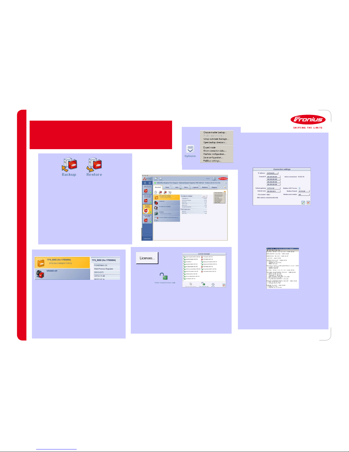
13 SEP 12
/ Battery Charging Systems / Welding Technology / Solar Electronics
Fronius Xplorer
Fronius XplorerFronius Xplorer
Fronius Xplorer
Overview Tab
This display shows everything that is
currently connected through
LocalNet.
In addition, hardware, firmware, and
database information will be
displayed for each piece of
equipment that is selected (yellow bar
indicated selection⁄.
By using these buttons, Weld Jobs
can be saved to a computer (Backup⁄
or loaded from one (Restore⁄.
As long as the synergic lines exist in
the database loaded into the
machine, any Weld Job set can be
used.
These job sets are NOT compatible
with other Backup/Restore tools.
The license button is used to see which
software options are loaded into the
machine. Unlocked options are displayed
as green locks while locked ones are red
locks. New ones can be loaded in using
the Enter new software code button.
The Options button opens up a
submenu that has several useful
functions including the Show
connection data and Machine
Configuration selections.
Show connection data shows
the IP and connection interface for
any Ethernet card connected to
LocalNet. This option also allows
for these settings to be changed as
needed.
Machine Configuration outputs a
text file that includes all equipment
connected through LocalNet. Serial
numbers, firmware, and hardware
versions are also saved.
---- 85
85 85
85 ----
Page 88

13 SEP 12
/ Battery Charging Systems / Welding Technology / Solar Electronics
Fronius Xplorer
Job and Docu Tab
The Job tab give a quick view of jobs
loaded into the welder, the weld
parameters for these jobs, and any
changes that have been made recently.
Group and job names can be changed to
reflect the application and/or production
floor.
A job can be copied to one or more
other locations and than customized to
suit the needs of the application.
When a change is made, there is an
option to either accept the change or
undo the change.
Finally, a history of job changes is kept
that can not only be reviewed but also
loaded from should the need arise.
The Docu tab allows you to monitor the
weld parameters of one or more welders
AFTER they have completed a weld.
The parameters can be customized
based on the user desires by right
clicking on the data screen.
Previous data can be viewed by opening
up older files. Each days welding is
stored for future viewing and/or
importing.
The Options button opens up a
submenu that has several useful
functions including the Set
consumption figures and the
Country settings selections.
The Set consumption figures
allows you to set the costs of your
wire, gas and energy as well as
specify the travel speeds used during
the welding process.
The Country settings changes
the unit of measurement between metric
and imperial depending on the needs of the
plant.
- 86
8686
86 -
Page 89

13 SEP 12
/ Battery Charging Systems / Welding Technology / Solar Electronics
Troubleshooting
---- 87
87 87
87 ----
Weld System
• Many factors can effect weld quality and many times the poor quality will come from wear parts rather than weld
settings. However in some cases the weld quality can be effected by the weld settings. This would be the case if the
settings have been adjusted from settings that were known to work for specific process. Also a change in base
materials or parts can make the predetermined settings no longer the best viable settings to produce quality welds.
• When trouble shooting weld quality it is very important to go through a number of checks prior to designating a
certain cause to the problem.
• These checks include:
Consumables
Loose Connections
Settings that differ from pre determined settings
Torch Quality
Torch Itself internal/externally or liner itself
Wire Drive unit
Damaged or loose connections
Damage to drive motor or drive rolls
Firmware
Hose Pack
Damage to any connections, hoses or cabling included in the hose pack
Power Source
Internal Hardware or Firmware
Page 90

13 SEP 12
/ Battery Charging Systems / Welding Technology / Solar Electronics
Troubleshooting
---- 88
88 88
88 ----
Welder Error Codes
DSP xxx
Error with the Digital Signal Processor – Reload firmware/database or replace UST
EFD xxx
Error with the wire feed system, refer to wire feeder error codes for more details
Err 049, 051, and 052
Error detected in mains power input (phase missing or voltage too low/high). Check mains and then replace NT 24
Err 050
Intermediate circuit imbalance. Further troubleshooting needed
Err IP
Primary transformer over-current detected. Check the secondary power module and the BPS board.
Err PE
Voltage detected on earth ground. Check for isolation between welding ground points and earth ground points.
No H2O
Error with the coolant system, check cooler for operation and system for good flow.
No Prg
Synergic line selected doesn’t exist. Verify synergic line settings, reprogram UST, or replace UST.
STOP
Communication or E-Stop condition with robot. Check for Robot Ready and Error Reset signals from robot.
Tsx xxx and Tpx xxx
Internal temperature errors on the secondary or primary side. Check for duty cycle and proper air flow.
Page 91

13 SEP 12
/ Battery Charging Systems / Welding Technology / Solar Electronics
Error Codes
Error CodesError Codes
Error Codes
- Few error codes refer directly to a problem with the torch. However, a large
number of them can indirectly be caused by the torch or the torch position.
Physical Clues
Physical CluesPhysical Clues
Physical Clues
- The torch neck needs to be inspected for excessive wear or damage
caused by the welding process. As needed, it should be cleaned of buildup spatter and other contaminates.
- Consumables should be checked regularly and cleaned/changed as
needed. Consumables include
Gas Nozzle: free of spatter build-up and excessive conal damage.
Torch Tip: free spatter build-up and excessive wire wear.
Spatter Guard: gas holes free of blockage and excessive part
damage
Nozzle Stock: gas holes free of blockage, excessive spatter build-
up, and stripped threads.
- Ensure pressure and drive rolls (if equipped⁄ are clean and not excessively
worn or damaged.
Electronics/Settings
Electronics/SettingsElectronics/Settings
Electronics/Settings
- Some problems with the torch can be addressed by 1stlevel welding
settings in the power source.
Troubleshooting
Torches
---- 89
89 89
89 ----
Page 92

13 SEP 12
/ Battery Charging Systems / Welding Technology / Solar Electronics
Troubleshooting
---- 90
90 90
90 ----
Wire Feeder Error Codes
EFD 1.x through 7.x
These are all internal logic errors and require a software update or SR board change
EFD 7.1
Configuration Memory (config mem) error
EFD 8.x
Main motor or push pull motor current errors
EFD 9.x
Main motor voltage errors
EFD 10.x
Internal logic errors between the SR-xx and the PM-xx board
EFD 11.x
Main motor and push pull motor alignment errors
EFD 12.x
Main motor and push pull motor movement errors (not to be confused with encoder errors)
EFD 15.x
Wire buffer errors (CMT, only active when welding)
EFD 30.x
Local High Speed Bus (LHSB) communication error
EFD 31.x
Encoder feedback errors.
 Loading...