

Page 1

Fronius prints on elemental chlorine free paper (ECF) sourced from certified sustainable forests (FSC).
/ Perfect Charging / Perfect Welding / Solar Energy
TPS 320i C
Operating instructions
EN
MIG/MAG power source
42,0426,0113,EN 033-14012021
Page 2

Page 3

Contents
Safety rules 9
Explanation of safety notices 9
General 9
Proper use 9
Mains connection 10
Environmental conditions 10
Obligations of the operator 10
Obligations of personnel 11
Residual current protective device 11
Protecting yourself and others 11
Noise emission values 11
Danger from toxic gases and vapours 12
Danger from flying sparks 12
Risks from mains current and welding current 13
Meandering welding currents 14
EMC Device Classifications 14
EMC measures 14
EMF measures 15
Specific hazards 15
Requirement for the shielding gas 16
Danger from shielding gas cylinders 16
Danger from escaping shielding gas 17
Safety measures at the installation location and during transport 17
Safety measures in normal operation 17
Commissioning, maintenance and repair 18
Safety inspection 18
Disposal 19
Safety symbols 19
Data protection 19
Copyright 19
EN
General information 21
General 23
Device concept 23
Functional principle 23
Application areas 23
Conformities 24
Bluetooth trademarks 25
Warning notices on the device 25
Description of the warning notices on the device 27
Welding packages, welding characteristics and welding processes 29
General 29
Welding packages 29
Welding characteristics 29
Summary of MIG/MAG pulse synergic welding 32
Summary of MIG/MAG standard synergic welding 32
Summary of the PMC process 32
Summary of the LSC process 32
Summary of SynchroPulse welding 32
Summary of the CMT process 32
Short description of the CMT Cycle Step welding process 33
System components 34
General 34
Overview 34
Options 35
Controls, connections and mechanical components 37
Control panel 39
3
Page 4

General 39
Safety 39
Control panel 40
Connections, switches and mechanical components 42
TPS 320i C power source 42
Operating concept 45
Input options 47
General 47
Turning/pressing the adjusting dial 47
Pressing buttons 48
Pressing on the display 48
Display and status line 49
Display 49
Status bar 50
Status bar – Current limit reached 51
Installation and commissioning 53
Minimum equipment needed for welding task 55
General 55
MIG/MAG gas-cooled welding 55
MIG/MAG water-cooled welding 55
Manual CMT welding 55
TIG DC welding 55
MMA welding 55
Before installation and commissioning 56
Safety 56
Proper use 56
Setup regulations 56
Mains connection 56
Generator-powered operation 57
Information on system components 57
Connecting the mains cable 58
General 58
Stipulated mains cables 58
Safety 58
Connecting the mains cable - general 58
Commissioning the TPS 320i C 61
Safety 61
General 61
Recommendation for water-cooled applications 61
Connecting the gas cylinder 61
Establishing a ground earth connection 62
Connecting the welding torch 63
Inserting/replacing feed rollers 63
Inserting the wirespool 64
Inserting the basket-type spool 65
Feeding in the wire electrode 67
Setting the contact pressure 68
Adjusting the brake 68
Design of the brake 69
Performing R/L alignment 69
Locking and unlocking the power source using the NFC key 70
General remarks 70
Locking and unlocking the power source using the NFC key 70
Welding 73
MIG/MAG modes 75
General 75
Symbols and their explanations 75
2-step mode 76
4
Page 5

4-step mode 76
Special 4-step mode 77
Special 2-step mode 77
Spot welding 78
MIG/MAG and CMT welding 79
Safety 79
MIG/MAG and CMT welding – overview 79
Switching on the power source 79
Setting the welding process and operating mode 80
Selecting the filler metal and shielding gas 81
Setting the welding parameters 82
Setting the shielding gas flow rate 83
MIG/MAG or CMT welding 83
MIG/MAG and CMT welding parameters 84
Welding parameters for MIG/MAG pulse synergic welding, for CMT welding and PMC welding 84
Welding parameters for MIG/MAG standard synergic welding and LSC welding 85
Welding parameters for MIG/MAG standard manual welding 86
Explanation of footnotes 86
EasyJob mode 87
General 87
Activating EasyJob mode 87
Storing EasyJob operating points 88
Retrieving EasyJob operating points 88
Deleting EasyJob operating points 89
Job mode 90
General 90
Storing settings as a job 90
Job welding - retrieving a job 91
Renaming a job 92
Deleting a job 93
Loading a job 94
Optimize job 95
Setting correction limits for a job 96
Pre-settings for "Save as Job" 98
Spot welding 100
Spot welding 100
TIG welding 103
Safety 103
Preparations 103
TIG welding 104
Igniting the arc 106
Finishing welding 107
MMA welding 108
Safety 108
Preparations 108
MMA welding 109
Welding parameters for manual metal arc welding 112
EN
Process parameters 113
Overview 115
Overview - Process parameters, Common 115
Overview – components and monitoring process parameters 115
Overview – Job process parameters 115
Process parameters, General 116
Process parameters for start of welding/end of welding 116
Process parameters for Gas-Setup 117
Process parameters for process control 118
Penetration stabilizer 118
Arc length stabilizer 120
Combination of penetration stabilizer and arc length stabilizer 122
Process parameters for SynchroPulse 123
5
Page 6

Process parameters for Process mix 125
Process parameters for CMT Cycle Step 128
Process parameters for spot welding 129
R/L-check / alignment 129
Process parameters for TIG/MMA/SMAW setup 130
Components and monitoring process parameters 134
Process parameters for components 134
System adjust 135
Setting process parameters for arc break monitoring 137
Process parameters for wire stick contact tip 138
Process parameters for wire stick workpiece 140
Process parameter for wire end monitoring 141
Process parameters for gas monitoring 142
Motor force monitoring 144
Process parameters, Job 146
Optimising job process parameters 146
Process parameters for correction limits 148
Process parameters for pre-settings for "Save as Job" 149
Defaults 153
Defaults 155
General remarks 155
Overview 155
Defaults - view 156
Setting the language 156
Setting Units/Standards 157
Setting the time and date 158
Retrieving system data 159
Displaying characteristics 162
Defaults - System 163
Retrieving device information 163
Restoring factory settings 163
Restoring the website password 164
Mode Setup: Setting the special 4-step mode "Guntrigger", special display for JobMaster, spot
welding and torch trigger job selection
Setting network parameters manually 167
Setting up the WLAN 168
Bluetooth setup 169
Power source configurations 171
Wire feeder setup 172
Interface setup 173
Defaults - Documentation 176
Setting the sampling rate 176
Viewing the logbook 177
Activate/deactivate limit value monitoring 178
Defaults - Administration 180
General remarks 180
Explanation of terms used 180
Pre-defined roles and users 180
Overview 181
Administrator and creating roles 182
Recommendation for creating roles and users 182
Create administrator key 183
Creating roles 184
Copy roles 186
Creating a user 187
Creating a user 187
Copying users 188
Editing roles / users, deactivating user management 190
Editing roles 190
Deleting roles 191
165
6
Page 7

Editing users 192
Deleting users 193
Deactivating user management 194
Lost NFC administrator key? 195
CENTRUM - Central User Management 196
Activating the CENTRUM server 196
SmartManager - The power source website 197
SmartManager - The power source website 199
General remarks 199
Opening and logging into the power source SmartManager 199
Help function, should you be unable to log in 200
Changing password / logging off 200
Settings 201
Language selection 201
Status indicator 202
Fronius 202
Current system data 203
Current system data 203
Documentation, logbook 204
Documentation 204
Job-Data 206
Job data 206
Job overview 206
Editing a job 206
Importing a job 207
Exporting a job 207
Exporting job(s) as… 207
Power source settings 208
Process parameters 208
Name & location 208
MQTT settings 208
OPC UA settings 208
Backup & Restore 209
General remarks 209
Backup & Restore 209
Automatic backup 210
Signal visualisation 211
Signal visualisation 211
User management 212
General 212
Users 212
User roles 212
Export & import 213
CENTRUM 213
Overview 214
Overview 214
Expand all groups / Reduce all groups 214
Save as XML-file 214
Update 215
Update 215
Searching for an update file (performing the update) 215
Fronius WeldConnect 217
Function Packages 218
Function Packages 218
Welding Packages 218
Special characteristics 218
Options 218
Installing a function package 218
Synergic lines overview 219
Characteristics overview 219
EN
7
Page 8

Showing/hiding the filter 219
Screenshot 220
Screenshot 220
Interface 221
Interface 221
Troubleshooting and maintenance 223
Troubleshooting 225
General 225
Safety 225
MIG/MAG welding – Current limit 225
Power source - troubleshooting 226
Care, maintenance and disposal 230
General 230
Safety 230
At every start-up 230
Every 2 months 230
Every 6 months 230
Updating firmware 230
Disposal 231
Appendix 233
Average consumption values during welding 235
Average wire electrode consumption during MIG/MAG welding 235
Average shielding gas consumption during MIG/MAG welding 235
Average shielding gas consumption during TIG welding 235
Technical data 236
Explanation of the term "duty cycle" 236
Special voltages 236
Overview with critical raw materials, year of production of the device 236
TPS 320i C 238
TPS 320i C /nc 240
TPS 320i C /S/nc 242
TPS 320i C /MV/nc 244
Radio parameters 246
8
Page 9

Safety rules
EN
Explanation of
safety notices
DANGER!
Indicates immediate danger.
If not avoided, death or serious injury will result.
▶
WARNING!
Indicates a potentially hazardous situation.
If not avoided, death or serious injury may result.
▶
CAUTION!
Indicates a situation where damage or injury could occur.
If not avoided, minor injury and/or damage to property may result.
▶
NOTE!
Indicates a risk of flawed results and possible damage to the equipment.
General The device is manufactured using state-of-the-art technology and according to recog-
nised safety standards. If used incorrectly or misused, however, it can cause:
- injury or death to the operator or a third party,
- damage to the device and other material assets belonging to the operating company,
- inefficient operation of the device.
All persons involved in commissioning, operating, maintaining and servicing the device
must:
- be suitably qualified,
- have sufficient knowledge of welding and
- read and follow these operating instructions carefully.
The operating instructions must always be at hand wherever the device is being used. In
addition to the operating instructions, attention must also be paid to any generally applicable and local regulations regarding accident prevention and environmental protection.
All safety and danger notices on the device
- must be in a legible state,
- must not be damaged,
- must not be removed,
- must not be covered, pasted or painted over.
For the location of the safety and danger notices on the device, refer to the section
headed "General" in the operating instructions for the device.
Before switching on the device, rectify any faults that could compromise safety.
This is for your personal safety!
Proper use The device is to be used exclusively for its intended purpose.
9
Page 10

The device is intended solely for the welding processes specified on the rating plate.
Any use above and beyond this purpose is deemed improper. The manufacturer shall not
be held liable for any damage arising from such usage.
Proper use includes:
- carefully reading and following all the instructions given in the operating instructions
- studying and obeying all safety and danger notices carefully
- performing all stipulated inspection and maintenance work.
Never use the device for the following purposes:
- Thawing out pipes
- Charging batteries
- Starting engines
The device is designed for use in industry and the workshop. The manufacturer accepts
no responsibility for any damage caused through use in a domestic setting.
The manufacturer likewise accepts no liability for inadequate or incorrect results.
Mains connection Devices with a higher rating may affect the energy quality of the mains due to their cur-
rent consumption.
This may affect a number device types in terms of:
- Connection restrictions
-
Criteria with regard to the maximum permissible mains impedance
-
Criteria with regard to the minimum short-circuit power requirement
*)
*)
Environmental
conditions
*)
at the interface with the public grid
see "Technical data"
In this case, the plant operator or the person using the device should check whether the
device may be connected, where appropriate by discussing the matter with the power
supply company.
IMPORTANT! Ensure that the mains connection is earthed properly
Operation or storage of the device outside the stipulated area will be deemed as not in
accordance with the intended purpose. The manufacturer shall not be held liable for any
damage arising from such usage.
Ambient temperature range:
- during operation: -10 °C to + 40 °C (14 °F to 104 °F)
- during transport and storage: -20 °C to +55 °C (-4 °F to 131 °F)
Relative humidity:
- up to 50% at 40 °C (104 °F)
- up to 90% at 20 °C (68 °F)
The surrounding air must be free from dust, acids, corrosive gases or substances, etc.
Can be used at altitudes of up to 2000 m (6561 ft. 8.16 in.)
Obligations of the
operator
10
The operator must only allow persons to work with the device who:
- are familiar with the fundamental instructions regarding safety at work and accident
prevention and have been instructed in how to use the device
- have read and understood these operating instructions, especially the section
"safety rules", and have confirmed as much with their signatures
- are trained to produce the required results.
Page 11

Checks must be carried out at regular intervals to ensure that operators are working in a
safety-conscious manner.
EN
Obligations of
personnel
Residual current
protective device
Protecting yourself and others
Before using the device, all persons instructed to do so undertake:
- to observe the basic instructions regarding safety at work and accident prevention
- to read these operating instructions, especially the "Safety rules" section and sign to
confirm that they have understood them and will follow them.
Before leaving the workplace, ensure that people or property cannot come to any harm
in your absence.
Local regulations and national guidelines may require a residual current protective
device when connecting equipment to the public grid.
The type of residual current protective device recommended by the manufacturer for the
equipment is indicated in the technical data.
Anyone working with the device exposes themselves to numerous risks, e.g.
- flying sparks and hot pieces of metal
- Arc radiation, which can damage eyes and skin
- Hazardous electromagnetic fields, which can endanger the lives of those using cardiac pacemakers
- Risk of electrocution from mains current and welding current
- Greater noise pollution
- Harmful welding fumes and gases
Suitable protective clothing must be worn when working with the device. The protective
clothing must have the following properties:
- Flame-resistant
- Insulating and dry
- Covers the whole body, is undamaged and in good condition
- Safety helmet
- Trousers with no turn-ups
Protective clothing refers to a variety of different items. Operators should:
- Protect eyes and face from UV rays, heat and sparks using a protective visor and
regulation filter
- Wear regulation protective goggles with side protection behind the protective visor
- Wear stout footwear that provides insulation even in wet conditions
- Protect the hands with suitable gloves (electrically insulated and providing protection
against heat)
- Wear ear protection to reduce the harmful effects of noise and to prevent injury
Keep all persons, especially children, out of the working area while any devices are in
operation or welding is in progress. If, however, there are people in the vicinity:
- Make them aware of all the dangers (risk of dazzling by the arc, injury from flying
sparks, harmful welding fumes, noise, possible risks from mains current and welding
current, etc.)
- Provide suitable protective equipment
- Alternatively, erect suitable safety screens/curtains.
Noise emission
values
The device generates a maximum sound power level of <80 dB(A) (ref. 1pW) when idling
and in the cooling phase following operation at the maximum permissible operating point
under maximum rated load conditions according to EN 60974-1.
11
Page 12

It is not possible to provide a workplace-related emission value during welding (or cutting) as this is influenced by both the process and the environment. All manner of different welding parameters come into play, including the welding process (MIG/MAG, TIG
welding), the type of power selected (DC or AC), the power range, the type of weld
metal, the resonance characteristics of the workpiece, the workplace environment, etc.
Danger from
toxic gases and
vapours
The fumes produced during welding contain harmful gases and vapours.
Welding fumes contain substances that cause cancer, as stated in Monograph 118 of the
International Agency for Research on Cancer.
Use at-source extraction and a room extraction system.
If necessary, use a welding torch with an integrated extraction device.
Keep your face away from welding fumes and gases.
Fumes and hazardous gases
- must not be breathed in
- must be extracted from the working area using appropriate methods.
Ensure an adequate supply of fresh air. Ensure that there is a ventilation rate of at least
20 m³ per hour at all times.
Otherwise, a welding helmet with an air supply must be worn.
If there is any doubt about whether the extraction capacity is sufficient, the measured
toxic emission values should be compared with the permissible limit values.
The following components are responsible, amongst other things, for the degree of toxicity of welding fumes:
- Metals used for the workpiece
- Electrodes
- Coatings
- Cleaners, degreasers, etc.
- Welding process used
Danger from flying sparks
The relevant material safety data sheets and manufacturer's specifications for the listed
components should therefore be studied carefully.
Recommendations for trade fair scenarios, risk management measures and for identifying working conditions can be found on the European Welding Association website under
Health & Safety (https://european-welding.org).
Flammable vapours (e.g. solvent fumes) should be kept away from the arc's radiation
area.
Close the shielding gas cylinder valve or main gas supply if no welding is taking place.
Flying sparks may cause fires or explosions.
Never weld close to flammable materials.
Flammable materials must be at least 11 metres (36 ft. 1.07 in.) away from the arc, or
alternatively covered with an approved cover.
A suitable, tested fire extinguisher must be available and ready for use.
Sparks and pieces of hot metal may also get into adjacent areas through small gaps or
openings. Take appropriate precautions to prevent any danger of injury or fire.
12
Page 13

Welding must not be performed in areas that are subject to fire or explosion or near
sealed tanks, vessels or pipes unless these have been prepared in accordance with the
relevant national and international standards.
Do not carry out welding on containers that are being or have been used to store gases,
propellants, mineral oils or similar products. Residues pose an explosive hazard.
EN
Risks from mains
current and welding current
An electric shock is potentially life threatening and can be fatal.
Do not touch live parts either inside or outside the device.
During MIG/MAG welding and TIG welding, the welding wire, the wirespool, the feed
rollers and all pieces of metal that are in contact with the welding wire are live.
Always set the wirefeeder up on a sufficiently insulated surface or use a suitable, insulated wirefeeder holder.
Make sure that you and others are protected with an adequately insulated, dry base or
cover for the earth or ground potential. This base or cover must extend over the entire
area between the body and the earth or ground potential.
All cables and leads must be secured, undamaged, insulated and adequately dimensioned. Replace loose connections and scorched, damaged, or inadequately dimensioned cables and leads immediately.
Use the handle to ensure the power connections are tight before every use.
In the case of power cables with a bayonet connector, rotate the power cable around the
longitudinal axis by at least 180° and pretension.
Do not wrap cables or leads around the body or parts of the body.
The electrode (rod electrode, tungsten electrode, welding wire, etc.) must
- never be immersed in liquid for cooling
- Never touch the electrode when the power source is switched on.
Double the open circuit voltage of a power source can occur between the welding electrodes of two power sources. Touching the potentials of both electrodes at the same time
may be fatal under certain circumstances.
Arrange for the mains cable to be checked regularly by a qualified electrician to ensure
the ground conductor is functioning properly.
Protection class I devices require a mains supply with ground conductor and a connector
system with ground conductor contact for proper operation.
Operation of the device on a mains supply without ground conductor and on a socket
without ground conductor contact is only permitted if all national regulations for protective
separation are observed.
Otherwise, this is considered gross negligence. The manufacturer shall not be held liable
for any damage arising from such usage.
If necessary, provide adequate earthing for the workpiece.
Switch off unused devices.
Wear a safety harness if working at height.
Before working on the device, switch it off and pull out the mains plug.
Attach a clearly legible and easy-to-understand warning sign to the device to prevent
anyone from plugging the mains plug back in and switching it on again.
After opening the device:
- Discharge all live components
- Ensure that all components in the device are de-energised.
13
Page 14

If work on live parts is required, appoint a second person to switch off the main switch at
the right moment.
Meandering welding currents
EMC Device Classifications
If the following instructions are ignored, meandering welding currents can develop with
the following consequences:
- Fire hazard
- Overheating of parts connected to the workpiece
- Irreparable damage to ground conductors
- Damage to device and other electrical equipment
Ensure that the workpiece is held securely by the workpiece clamp.
Attach the workpiece clamp as close as possible to the area that is to be welded.
Position the device with sufficient insulation against electrically conductive environments,
e.g. Insulation against conductive floor or insulation to conductive racks.
If distribution boards, twin-head mounts, etc., are being used, note the following: The
electrode of the welding torch / electrode holder that is not used is also live. Make sure
that the welding torch / electrode holder that is not used is kept sufficiently insulated.
In the case of automated MIG/MAG applications, ensure that only an insulated wire electrode is routed from the welding wire drum, large wirefeeder spool or wirespool to the
wirefeeder.
Devices in emission class A:
- Are only designed for use in industrial settings
- Can cause line-bound and radiated interference in other areas
Devices in emission class B:
- Satisfy the emissions criteria for residential and industrial areas. This is also true for
residential areas in which the energy is supplied from the public low-voltage mains.
EMC device classification as per the rating plate or technical data.
EMC measures In certain cases, even though a device complies with the standard limit values for emis-
sions, it may affect the application area for which it was designed (e.g. when there is
sensitive equipment at the same location, or if the site where the device is installed is
close to either radio or television receivers).
If this is the case, then the operator is obliged to take appropriate action to rectify the
situation.
Check and evaluate the immunity to interference of nearby devices according to national
and international regulations. Examples of equipment that may be susceptible to interference from the device include:
- Safety devices
- Power, signal and data transfer lines
- IT and telecommunications devices
- Measuring and calibrating devices
Supporting measures for avoidance of EMC problems:
1. Mains supply
- If electromagnetic interference arises despite correct mains connection, addi-
tional measures are necessary (e.g. use a suitable line filter).
14
Page 15

2. Welding power leads
- must be kept as short as possible
- must run close together (to avoid EMF problems)
- must be kept well apart from other leads
3. Equipotential bonding
4. Earthing of the workpiece
- If necessary, establish an earth connection using suitable capacitors.
5. Shielding, if necessary
- Shield off other nearby devices
- Shield off entire welding installation
EMF measures Electromagnetic fields may pose as yet unknown risks to health:
- effects on the health of others in the vicinity, e.g. wearers of pacemakers and hearing aids
- wearers of pacemakers must seek advice from their doctor before approaching the
device or any welding that is in progress
- for safety reasons, keep distances between the welding cables and the welder's
head/torso as large as possible
- do not carry welding cables and hosepacks over the shoulders or wind them around
any part of the body
EN
Specific hazards Keep hands, hair, clothing and tools away from moving parts. For example:
- Fans
- Cogs
- Rollers
- Shafts
- Wirespools and welding wires
Do not reach into the rotating cogs of the wire drive or into rotating drive components.
Covers and side panels may only be opened/removed while maintenance or repair work
is being carried out.
During operation
- Ensure that all covers are closed and all side panels are fitted properly.
- Keep all covers and side panels closed.
The welding wire emerging from the welding torch poses a high risk of injury (piercing of
the hand, injuries to the face and eyes, etc.).
Therefore always keep the welding torch away from the body (devices with wire-feed
unit) and wear suitable protective goggles.
Never touch the workpiece during or after welding - risk of burns.
Slag can jump off cooling workpieces. The specified protective equipment must therefore
also be worn when reworking workpieces, and steps must be taken to ensure that other
people are also adequately protected.
Welding torches and other parts with a high operating temperature must be allowed to
cool down before handling.
Special provisions apply in areas at risk of fire or explosion - observe relevant
national and international regulations.
Power sources for work in areas with increased electric risk (e.g. near boilers) must carry
the "Safety" sign. However, the power source must not be located in such areas.
Risk of scalding from escaping coolant. Switch off cooling unit before disconnecting
coolant flow or return lines.
15
Page 16

Observe the information on the coolant safety data sheet when handling coolant. The
coolant safety data sheet may be obtained from your service centre or downloaded from
the manufacturer's website.
Use only suitable load-carrying equipment supplied by the manufacturer when transporting devices by crane.
- Hook chains and/or ropes onto all suspension points provided on the load-carrying
equipment.
- Chains and ropes must be at the smallest angle possible to the vertical.
- Remove gas cylinder and wire-feed unit (MIG/MAG and TIG devices).
If the wire-feed unit is attached to a crane holder during welding, always use a suitable,
insulated wirefeeder hoisting attachment (MIG/MAG and TIG devices).
If the device has a carrying strap or handle, this is intended solely for carrying by hand.
The carrying strap is not to be used if transporting with a crane, counterbalanced lift truck
or other mechanical hoist.
All lifting accessories (straps, handles, chains, etc.) used in connection with the device or
its components must be tested regularly (e.g. for mechanical damage, corrosion or
changes caused by other environmental factors).
The testing interval and scope of testing must comply with applicable national standards
and directives as a minimum.
Odourless and colourless shielding gas may escape unnoticed if an adapter is used for
the shielding gas connection. Prior to assembly, seal the device-side thread of the
adapter for the shielding gas connection using suitable Teflon tape.
Requirement for
the shielding gas
Danger from
shielding gas cylinders
Especially with ring lines, contaminated shielding gas can cause damage to equipment
and reduce welding quality.
Meet the following requirements regarding shielding gas quality:
- Solid particle size < 40 µm
- Pressure condensation point < -20 °C
- Max. oil content < 25 mg/m³
Use filters if necessary.
Shielding gas cylinders contain gas under pressure and can explode if damaged. As the
shielding gas cylinders are part of the welding equipment, they must be handled with the
greatest of care.
Protect shielding gas cylinders containing compressed gas from excessive heat, mechanical impact, slag, naked flames, sparks and arcs.
Mount the shielding gas cylinders vertically and secure according to instructions to prevent them falling over.
Keep the shielding gas cylinders well away from any welding or other electrical circuits.
Never hang a welding torch on a shielding gas cylinder.
Never touch a shielding gas cylinder with an electrode.
16
Risk of explosion - never attempt to weld a pressurised shielding gas cylinder.
Only use shielding gas cylinders suitable for the application in hand, along with the correct and appropriate accessories (regulator, hoses and fittings). Only use shielding gas
cylinders and accessories that are in good condition.
Turn your face to one side when opening the valve of a shielding gas cylinder.
Page 17

Close the shielding gas cylinder valve if no welding is taking place.
Danger from
escaping shielding gas
Safety measures
at the installation
location and during transport
If the shielding gas cylinder is not connected, leave the valve cap in place on the cylinder.
The manufacturer's instructions must be observed as well as applicable national and
international regulations for shielding gas cylinders and accessories.
Risk of suffocation from the uncontrolled escape of shielding gas
Shielding gas is colourless and odourless and, in the event of a leak, can displace the
oxygen in the ambient air.
- Ensure an adequate supply of fresh air with a ventilation rate of at least 20 m³/hour.
- Observe safety and maintenance instructions on the shielding gas cylinder or the
main gas supply.
- Close the shielding gas cylinder valve or main gas supply if no welding is taking
place.
- Check the shielding gas cylinder or main gas supply for uncontrolled gas leakage
before every start-up.
A device toppling over could easily kill someone. Place the device on a solid, level surface such that it remains stable
- The maximum permissible tilt angle is 10°.
Special regulations apply in rooms at risk of fire or explosion
- Observe relevant national and international regulations.
EN
Use internal directives and checks to ensure that the workplace environment is always
clean and clearly laid out.
Only set up and operate the device in accordance with the degree of protection shown
on the rating plate.
When setting up the device, ensure there is an all-round clearance of 0.5 m (1 ft. 7.69
in.) to ensure that cooling air can flow in and out freely.
When transporting the device, observe the relevant national and local guidelines and
accident prevention regulations. This applies especially to guidelines regarding the risks
arising during transport.
Do not lift or transport operational devices. Switch off devices before transport or lifting.
Before transporting the device, allow coolant to drain completely and detach the following components:
- Wirefeeder
- Wirespool
- Shielding gas cylinder
After transporting the device, the device must be visually inspected for damage before
commissioning. Any damage must be repaired by trained service technicians before
commissioning the device.
Safety measures
in normal operation
Only operate the device when all safety devices are fully functional. If the safety devices
are not fully functional, there is a risk of
- injury or death to the operator or a third party
- damage to the device and other material assets belonging to the operator
- inefficient operation of the device
17
Page 18

Any safety devices that are not functioning properly must be repaired before switching on
the device.
Never bypass or disable safety devices.
Before switching on the device, ensure that no one is likely to be endangered.
Check the device at least once a week for obvious damage and proper functioning of
safety devices.
Always fasten the shielding gas cylinder securely and remove it beforehand if the device
is to be transported by crane.
Only the manufacturer's original coolant is suitable for use with our devices due to its
properties (electrical conductibility, anti-freeze agent, material compatibility, flammability,
etc.).
Only use suitable original coolant from the manufacturer.
Do not mix the manufacturer's original coolant with other coolants.
Only connect the manufacturer's system components to the cooling circuit.
The manufacturer accepts no liability for damage resulting from use of other system
components or a different coolant. In addition, all warranty claims will be forfeited.
Cooling Liquid FCL 10/20 does not ignite. The ethanol-based coolant can ignite under
certain conditions. Transport the coolant only in its original, sealed containers and keep
well away from any sources of ignition.
Used coolant must be disposed of properly in accordance with the relevant national and
international regulations. The coolant safety data sheet may be obtained from your service centre or downloaded from the manufacturer's website.
Check the coolant level before starting to weld, while the system is still cool.
Commissioning,
maintenance and
repair
Safety inspection The manufacturer recommends that a safety inspection of the device is performed at
It is impossible to guarantee that bought-in parts are designed and manufactured to meet
the demands made of them, or that they satisfy safety requirements.
- Use only original spare and wearing parts (also applies to standard parts).
- Do not carry out any modifications, alterations, etc. to the device without the manufacturer's consent.
- Components that are not in perfect condition must be replaced immediately.
- When ordering, please give the exact designation and part number as shown in the
spare parts list, as well as the serial number of your device.
The housing screws provide the ground conductor connection for earthing the housing
parts.
Only use original housing screws in the correct number and tightened to the specified
torque.
least once every 12 months.
18
The manufacturer recommends that the power source be calibrated during the same 12month period.
A safety inspection should be carried out by a qualified electrician
- after any changes are made
- after any additional parts are installed, or after any conversions
- after repair, care and maintenance has been carried out
- at least every twelve months.
Page 19

For safety inspections, follow the appropriate national and international standards and
directives.
Further details on safety inspection and calibration can be obtained from your service
centre. They will provide you on request with any documents you may require.
Disposal Do not dispose of this device with normal domestic waste! To comply with the European
Directive on Waste Electrical and Electronic Equipment and its implementation as
national law, electrical equipment that has reached the end of its life must be collected
separately and returned to an approved recycling facility. Any device that you no longer
require must either be returned to your dealer or given to one of the approved collection
and recycling facilities in your area. Ignoring this European Directive may have potentially adverse affects on the environment and your health!
Safety symbols Devices with the CE mark satisfy the essential requirements of the low-voltage and elec-
tromagnetic compatibility directives (e.g. relevant product standards of the EN 60 974
series).
Fronius International GmbH hereby declares that the device is compliant with Directive
2014/53/EU. The full text on the EU Declaration of Conformity can be found at the following address: http://www.fronius.com
EN
Devices marked with the CSA test mark satisfy the requirements of the relevant standards for Canada and the USA.
Data protection The user is responsible for the safekeeping of any changes made to the factory settings.
The manufacturer accepts no liability for any deleted personal settings.
Copyright Copyright of these operating instructions remains with the manufacturer.
The text and illustrations are all technically correct at the time of printing. We reserve the
right to make changes. The contents of the operating instructions shall not provide the
basis for any claims whatsoever on the part of the purchaser. If you have any suggestions for improvement, or can point out any mistakes that you have found in the instructions, we will be most grateful for your comments.
19
Page 20

20
Page 21

General information
21
Page 22

22
Page 23

General
Device concept The TPS 320i C MIG/MAG power source
is a completely digitised, microprocessorcontrolled inverter power source with
integrated 4-roller wire drive.
A modular design and potential for system
add-ons ensure a high degree of flexibility.
There is no longer an interconnecting
hosepack between the power source and
the wirefeeder. Its compact design makes
the TPS 320i C particularly suitable for
mobile applications.
The power source can be adapted to any
specific situation.
EN
Functional principle
Application areas The devices are used in workshops and industry for manual and automated applications
The central control and regulation unit of the power sources is coupled with a digital signal processor. The central control and regulation unit and the signal processor control
the entire welding process.
During the welding process, the actual data is measured continuously and the device
responds immediately to any changes. Control algorithms ensure that the desired target
state is maintained.
This results in:
- a precise welding process
- exact reproducibility of all results
- excellent weld properties.
with classical steel, galvanised sheets, chrome/nickel and aluminium.
The integral 4-roller wire drive, high performance and light weight of the TPS 320i C
power source makes it the ideal choice for portable applications on building sites or in
repair workshops.
23
Page 24

Conformities FCC
This equipment complies with the limit values for an EMC device class A digital device
pursuant to Part 15 of the FCC Rules. These limit values are intended to provide an
adequate level of protection against harmful emissions when the device is being used in
an industrial environment. This device generates and uses high-frequency energy and
can cause interference to radio communications if it is not installed and used according
to the Operating Instructions.
The use of this device in residential areas will probably cause harmful interference, in
which case the user will be obliged to correct the interference at their own expense.
FCC ID: QKWSPBMCU2
Industry Canada RSS
This device complies with the Industry Canada licence-exempt RSS standards. Its use is
subject to the following conditions:
(1) The device must not cause any harmful interference.
(2) The device must be able to cope with any interference, including that which could
IC: 12270A-SPBMCU2
EU
Conformity with Directive 2014/53 / EU - Radio Equipment Directive (RED)
adversely affect its operation.
When installing the antennae to be used for this transmitter, it is essential to maintain a
minimum distance of 20 cm from all people. They must not be set up or operated
together with another antenna or another transmitter. To comply with exposure to radio
frequency guidelines, the operating conditions of the transmitter must be available to
OEM integrators and end users.
ANATEL / Brazil
This device is operated on a secondary basis. It has no protection against harmful interference, even from devices of the same type.
This device cannot cause interference in systems operated on a primary basis.
This device complies with ANATEL's specific absorption rate limit values in relation to
exposure to high frequency electric, magnetic and electromagnetic fields.
IFETEL / Mexico
Operation of this device is subject to the following two conditions:
(1) The device must not cause any harmful interference.
(2) This device must accept any interference received, including interference that
may cause undesired operation.
NCC / Taiwan
In accordance with NCC regulations for low-power radio frequency devices:
Article 12
A certified low-power radio frequency device must not change the frequency, increase
the power or alter the characteristics and functions of the original structure without
approval.
24
Article 14
The use of low-power radio frequency devices must not adversely affect flight safety and
communications.
A detected malfunction must be deactivated and corrected immediately until no malfunction is present.
The notice in the preceding paragraph refers to radio communications operated in
accordance with the provisions of the Telecommunications Act. Low-power radio fre-
Page 25

quency devices must withstand interference from legitimate communications or radiological, electrical radio frequency devices for industrial, scientific and medical applications.
Thailand
EN
Bluetooth trademarks
Warning notices
on the device
The Bluetooth® word mark and logos are registered trademarks owned by Bluetooth
SIG, Inc. and any use of such marks by Fronius International GmbH is under license.
Other trademarks and trade names are those of their respective owners.
Warning notices and safety symbols are affixed to power sources with the CSA test mark
for use in North America (USA and Canada). These warning notices and safety symbols
must not be removed or painted over. They warn against incorrect operation, as this may
result in serious injury and damage.
25
Page 26

*)
*) on the inside of the device
Safety symbols on the rating plate:
Welding is dangerous. The following basic requirements must be met:
- Welders must be sufficiently qualified
- Suitable protective equipment must be used
- All persons not involved in the welding process must be kept at a safe distance
Do not use the functions described here until you have fully read and understood the following documents:
- These Operating Instructions
- All the Operating Instructions for the system components, especially the safety rules
26
Page 27
Description of the
AB
warning notices
on the device
For certain device versions, warning notices are affixed to the device.
The arrangement of the symbols may vary.
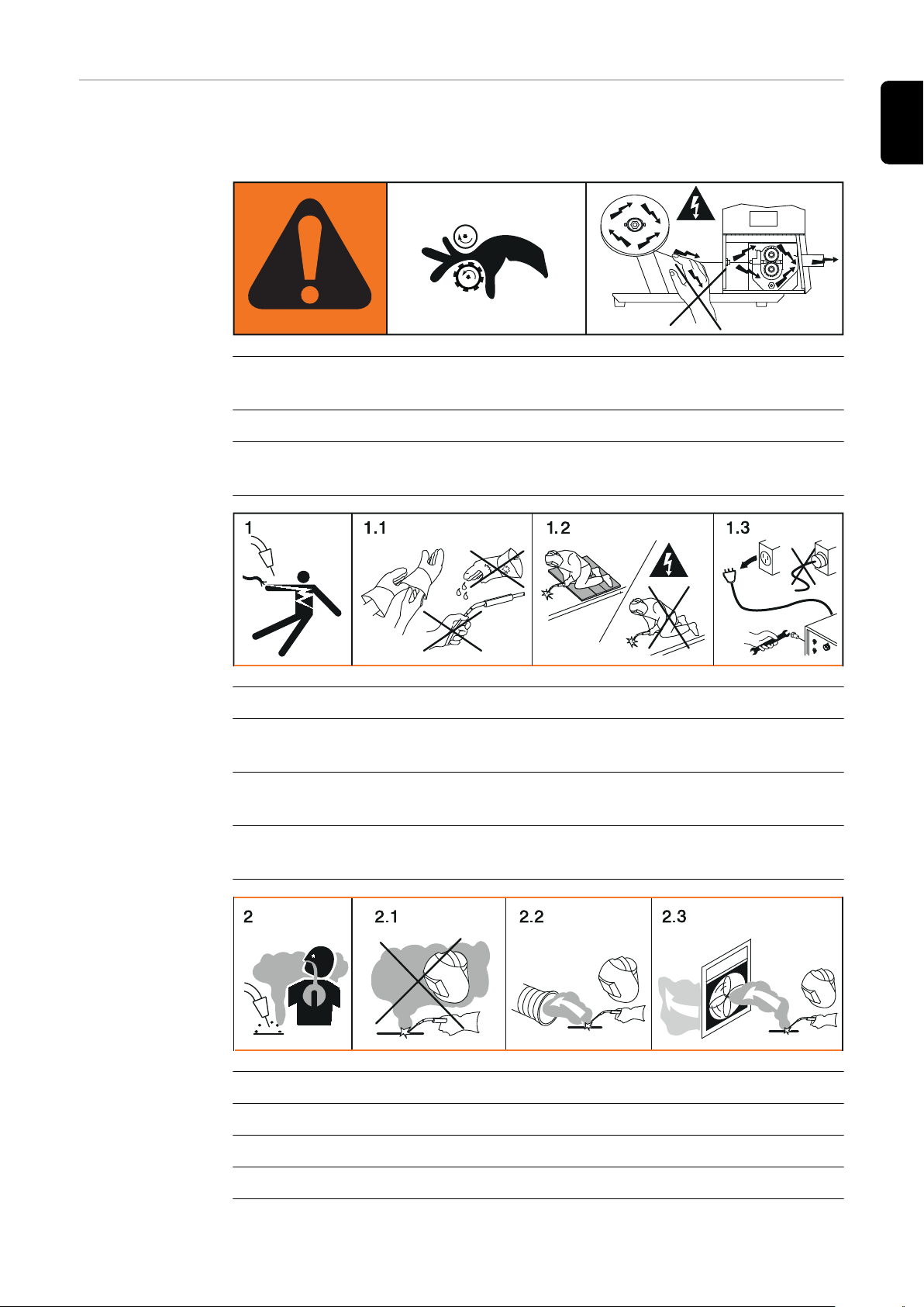
! Warning! Attention!
The symbols represent possible dangers.
A Drive rollers can injure fingers.
B The welding wire and drive parts are live during operation.
Keep hands and metal objects away!
EN
1. An electric shock can be fatal.
1.1 Wear dry, insulating gloves. Do not touch the wire electrode with bare hands. Do
not wear wet or damaged gloves.
1.2 Use a base that is insulated from the floor and work area to protect against elec-
tric shock.
1.3 Before working on the device, switch off the device and pull out the mains plug or
disconnect it from the power supply.
2. Inhalation of welding fumes can be harmful to health.
2.1 Keep your face away from any welding fumes.
2.2 Use forced-air ventilation or a local extraction system to remove welding fumes.
2.3 Remove welding fumes with a fan.
27
Page 28

3 Welding sparks can cause an explosion or fire.
xx,xxxx,xxxx *
3.1 Keep flammable materials away from the welding process. Never weld close to
flammable materials.
3.2 Welding sparks can cause a fire. Have fire extinguishers to hand. If necessary,
have a supervisor ready who can operate the fire extinguisher.
3.3 Do not weld on drums or closed containers.
4. Arc rays can burn the eyes and injure the skin.
4.1 Wear headgear and protective goggles. Use ear protection and a shirt collar with
button. Use a welding helmet with the correct tinting. Wear suitable protective
clothing over the entire body.
28
5. Before working on the system or welding:
undertake training on the device and read the instructions!
6. Do not remove or paint over the warning sticker.
* Manufacturer order number of the sticker
Page 29

Welding packages, welding characteristics and
welding processes
General Various welding packages, welding characteristics and welding processes are available
with TPSi power sources that enable a wide range of materials to be effectively welded.
Welding packages
The following welding packages are available for TPSi power sources:
- Standard Welding Package
(enables MIG/MAG standard synergic welding)
- Pulse Welding Package
(enables MIG/MAG pulse synergic welding)
- LSC Welding Package *
(enables the LSC process)
- PMC Welding Package **
(enables the PMC process)
- CMT Welding Package ***
(enables the CMT process)
* only in conjunction with the Standard Welding Package
** only in conjunction with the Pulse Welding Package
*** only in conjunction with the Standard Welding Package and the Pulse Welding
Package
EN
Welding characteristics
IMPORTANT! A TPSi power source without welding packages only offers the following
welding processes:
- MIG/MAG standard manual welding
- TIG welding
- MMA welding
Depending on the welding process and shielding gas mix, various process-optimised
welding characteristics are available when selecting the filler metal.
Examples of welding characteristics:
- MIG/MAG 3700 PMC Steel 1.0 mm M21 - arc blow *
- MIG/MAG 3450 PMC Steel 1.0 mm M21 - dynamic *
- MIG/MAG 3044 Pulse AlMg5 1.2 mm I1 - universal *
- MIG/MAG 2684 Standard Steel 0.9 mm M22 - root *
The additional designation (*) next to the welding process provides information about the
special properties and use of the welding characteristic.
The description of the characteristics is set out as follows:
Marking
Welding process
Properties
arc blow
PMC
Characteristic with improved arc break properties by deflecting the external magnetic
fields
29
Page 30

braze
CMT, LSC, PMC
Characteristics for brazing processes (high brazing speed, reliable wetting and good flow
of braze material)
braze+
CMT
Optimised characteristics for brazing processes with special "Braze+" gas nozzle (narrow
gas nozzle opening, high shielding gas flow rate)
cladding
CMT, LSC, PMC
Characteristic for cladding with low penetration, low dilution and wide weld seam flow for
improved wetting
dynamic
CMT, PMC, Pulse, Standard
Characteristics for high welding speeds with concentrated arc
flanged edge
CMT
Characteristics for flange welds with frequency and energy yield adjustments;
the edge is fully covered with the weld seam but not melted down
galvanized
CMT, LSC, PMC, Pulse, Standard
Characteristics for galvanised sheet surfaces (low zinc pore risk, reduced zinc melting
loss)
galvannealed
PMC
Characteristics for iron-zinc coated sheet surfaces
gap-bridging
CMT, PMC
Characteristics with very low heat input for optimum gap-bridging ability
hot spot
CMT
Characteristics with hot start sequence, specifically for plug welds and MIG/MAG spot
weld joints
mix **
PMC
also required: Pulse and PMC welding packages
Characteristics with process switch between pulsed and dip transfer arc
Specially for welding vertical-up seams with cyclic change between a hot and cold supporting process phase.
mix ** / ***
CMT
30
also required: CMT drive unit WF 60i Robacta Drive CMT, Pulse, Standard and CMT
welding packages
Characteristics with process switch between pulsed and CMT, where the CMT process is
initiated by wire movement reversal.
mix drive ***
PMC
Page 31

also required: PushPull drive unit WF 25i Robacta Drive or WF 60i Robacta Drive CMT,
Pulse and PMC welding packages
Characteristics with process switch between pulsed and dip transfer arc, where the dip
transfer arc is initiated by wire movement reversal.
multi arc
PMC
Characteristics for components being welded by several arcs each influencing the other
PCS **
PMC
Pulse Controlled Sprayarc - Direct transition from the concentrated pulsed arc to a short
spray arc. The advantages of pulsed and standard arcs combined in a single characteristic
pipe
PMC
Characteristic for pipe applications and positional welding on narrow gap applications
retro
CMT, Pulse, PMC, Standard
Characteristics with the properties of the TransPuls Synergic (TPS) predecessor series
ripple drive ***
PMC
EN
also required:
CMT drive unit WF 60i Robacta Drive CMT
Characteristics that behave like interval mode for clear weld rippling, especially with aluminium
root
CMT, LSC, Standard
Characteristics for root passes with powerful arc
TIME
PMC
Characteristics for welding with long stick out and TIME shielding gases
(T.I.M.E. = Transferred Ionized Molten Energy)
universal
CMT, PMC, Pulse, Standard
Characteristics for conventional welding tasks in renowned Fronius quality
WAAM
CMT
Characteristics with reduced heat input and greater stability at a higher deposition rate
for welding bead onto bead in adaptive structures
weld+
CMT
Characteristics for welding with short Stick out and Braze+ gas nozzle (Gas nozzle with
small opening and high flow velocity)
** Mixed process characteristics
*** Welding characteristics with special properties provided by additional hardware
31
Page 32

Summary of
MIG/MAG pulse
synergic welding
MIG/MAG pulse synergic
MIG/MAG pulse synergic welding is a pulsed-arc process with controlled material transfer.
In the base current phase, the energy supply is reduced to such an extent that the arc is
only just stable and the surface of the workpiece is preheated. In the pulsing current
phase, a precise current pulse ensures the targeted detachment of a droplet of welding
material.
This principle guarantees a low-spatter weld and precise working across the entire power
range.
Summary of
MIG/MAG standard synergic
welding
Summary of the
PMC process
MIG/MAG standard synergic
The MIG/MAG standard synergic welding process is a MIG/MAG welding process across
the entire power range of the power source with the following arc types:
Short circuit arc
Droplet transfer takes place during a short circuit in the lower power range.
Intermediate arc
The droplet increases in size on the end of the wire electrode and is transferred in the
mid-power range during the short circuit.
Spray arc
A short circuit-free transfer of material in the high power range.
PMC = Pulse Multi Control
PMC is a pulsed arc welding process with high-speed data processing, precise recording
of the process status and improved droplet detachment. Faster welding possible with a
stable arc and even fusion penetration.
Summary of the
LSC process
Summary of SynchroPulse welding
Summary of the
CMT process
32
LSC = Low Spatter Control
LSC is a new, low-spatter dip transfer arc process.The current is reduced before breaking the short-circuit bridge; re-ignition takes place at significantly lower welding current
values.
SynchroPulse is available for all processes (standard/pulsed/LSC/PMC).
Due to the cyclical change of welding power between two operating points, SynchroPulse achieves a flaking seam appearance and non-continuous heat input.
CMT = Cold Metal Transfer
A special CMT drive unit is required for the CMT process.
The reversing wire movement in the CMT process results in a droplet detachment with
improved dip transfer arc properties.
The advantages of the CMT process are as follows
Page 33

- Low heat input
- Less spattering
- Reduced emissions
- High process stability
The CMT process is suitable for:
- Joint welding, cladding and brazing – particularly in the case of high requirements in
terms of heat input and process stability
- Welding on light-gauge sheet with minimal distortion
- Special connections, such as copper, zinc, and steel/aluminium
NOTE!
A CMT reference book is available complete with typical applications; see
ISBN 978-3-8111-6879-4.
EN
Short description
of the CMT Cycle
Step welding process
CMT Cycle Step is the next step in the development of the CMT welding process. A special CMT drive unit is also required for this process.
CMT Cycle Step is the welding process with the lowest heat input.
The CMT Cycle Step welding process switches cyclically between CMT welding and
pauses of an adjustable duration.
These pauses in the welding process lower the heat input; the continuity of the weld
seam is maintained.
Individual CMT cycles are also possible. The size of the CMT spot welds is determined
by the number of CMT cycles.
33
Page 34

System components
(1)
(2)
(3)
(4)
General The power sources can be operated with various system components and options. This
makes it possible to optimise procedures and to simplify machine handling and operation, as necessitated by the particular field of application in which the power source is to
be used.
Overview
(1) Cooling units
(2) Power sources
(3) Robot accessories
(4) Trolley and gas cylinder holders
also:
- Welding torch
- Grounding cable and electrode cable
- Dust filter
- Additional current sockets
34
Page 35

Options
OPT/i gas flow rate sensor
OPT/i gas pressure sensor
OPT/i TPS 320i C CMT
OPT/i TPS 320i C TIG
OPT/i TPS 320i C wire end
OPT/i TPS 320i C PushPull
OPT/i TPS C wire feed
OPT/i TPS C polarity reverser
OPT/i TPS C QC DFS AD10
OPT/i TPS C QC DFS Powerliner
OPT/i TPS VRD
OPT/i Ext. Sensor connector
OPT/i TPS 320i C viewing window
OPT/i TPS C SpeedNet Connector
Optional second SpeedNet connection socket
EN
Factory-installed on the rear of the power source.
OPT/i TPS dust filter
IMPORTANT! Use of the OPT/i TPS dust filter option shortens the duty cycle.
OPT/i TPS C 2nd plus socket
2nd (+) current socket on the rear of the power source (option)
OPT/i TPS C 2nd earth socket
2nd (-) current socket on the rear of the power source (option)
OPT/i Synergic Lines
Option for enabling all special characteristics available on TPSi power sources;
this also automatically enables special characteristics created in future.
OPT/i GUN Trigger
Option for special functions in conjunction with the torch trigger
OPT/i Jobs
Option for Job mode
OPT/i Documentation
Option for the documentation function
OPT/i Interface Designer
Option for individual interface configuration
OPT/i WebJobEdit
Option for editing jobs via the SmartManager of the power source
OPT/i Limit Monitoring
Option for specifying the limit values for the welding current, welding voltage and wire
speed
35
Page 36

OPT/i Custom NFC - ISO 14443A
Option to use a customer-specific frequency band for key cards
OPT/i CMT Cycle Step
Option for adjustable, cyclical CMT welding process
OPT/i OPC-UA
Standardised data interface protocol
OPT/i MQTT
Standardised data interface protocol
36
Page 37

Controls, connections and mechan-
ical components
37
Page 38

38
Page 39

Control panel
General Welding parameters can be easily changed and selected using the adjusting dial.
The parameters are shown on the display while welding is in progress.
The synergic function ensures that other welding parameters are also adjusted whenever
an individual parameter is changed.
NOTE!
As a result of firmware updates, you may find that your device has certain functions that are not described in these operating instructions, or vice versa.
Certain illustrations may also differ slightly from the actual controls on your device, but
these controls function in exactly the same way.
EN
Safety
WARNING!
Danger from incorrect operation.
Possible serious injury and damage to property.
Do not use the functions described here until you have read and completely under-
▶
stood these Operating Instructions.
Do not use the functions described here until you have fully read and understood all
▶
of the Operating Instructions for the system components, in particular the safety
rules!
39
Page 40

Control panel
(1) (2) (5) (6)(3) (4)
43,0001,3547
No. Function
(1) USB port
For connecting USB flash drives (such as service dongles and licence keys).
IMPORTANT! The USB port is not electrically isolated from the welding circuit.
Therefore, devices that establish an electrical connection with another device
must not be connected to the USB port.
(2) Adjusting dial with turn/press function
To select elements, set values and scroll through lists
(3) Display (touchscreen)
- For operating the power source directly by pressing the buttons on the display
- For displaying values
- For navigating in the menu
(4) Key card reader for NFC keys
- For locking/unlocking the power source using NFC keys
- For logging on different users (with active user management and assigned
NFC keys)
NFC key = NFC card or NFC key ring
40
Page 41

(5) Wire threading button
To thread the wire electrode into the torch hosepack with no accompanying flow
of gas or current
(6) Gas-test button
For setting the required gas flow rate on the gas pressure regulator.
After pressing this button, gas flows for 30 seconds. Press the button again to
stop the gas flow prematurely.
EN
41
Page 42

Connections, switches and mechanical compon-
(3)
(4)
(5)
(6)
(2)
(1)
(7)
(10)
(9)
(8)
(14)
(13)
(12)
(11)
(16)(15)
ents
TPS 320i C power
source
Front
Side view
No. Function
(1) Welding torch connection
for connecting the welding torch
Rear
42
(2) (-) current socket with bayonet latch
used to connect the grounding cable during MIG/MAG welding
(3) Control panel cover
for protecting the control panel
(4) Control panel with display
for operating the power source
(5) (+) current socket with bayonet latch
(6) Blanking cover
reserved for the TMC connection socket of the TIG option
Page 43

(7) Mains cable with strain relief device
(8) Mains switch
for switching the power source on and off
(9) Blanking cover
reserved for TIG shielding gas connection option
(10) Blanking cover
reserved for optional 2nd (-) current socket or 2nd (+) current socket
(11) Blanking cover
reserved for external sensor option
(12) MIG/MAG shielding gas connection
(13) Blanking cover
reserved for the Ethernet connection socket
(14) Blanking cover
reserved for optional 2nd SpeedNet connection
(15) Wirespool holder with brake
for holding standard wirespools weighing up to 16 kg (35.27 lbs) and with a max.
diameter of 300 mm (11.81 in)
(16) 4 roller drive
EN
43
Page 44

44
Page 45

Operating concept
45
Page 46

46
Page 47

Input options
EN
General
NOTE!
As a result of firmware updates, you may find that there are functions available on
your device that are not described in these operating instructions or vice versa.
Certain illustrations may also differ slightly from the actual controls on your device, but
these controls function in exactly the same way.
WARNING!
Incorrect operation may result in serious injury or damage.
the following documents:
Do not use the functions described here until you have thoroughly read and under-
▶
stood these operating instructions
Do not use the functions described here until you have thoroughly read and under-
▶
stood all the operating instructions for the system components, especially the safety
rules
The following input options are available on the power source control panel:
- Turning/pressing the adjusting dial
- Pressing buttons
- Pressing on the display
Turning/pressing
the adjusting dial
Turn/press the adjusting dial to select elements, change values and scroll through lists.
Turn the adjusting dial to:
Select elements from the main area of the display:
- Turning right highlights the next element in the sequence.
- Turning left highlights the preceding element in the sequence.
- In vertical lists, turn right to scroll down and turn left to scroll up.
Change values:
- Turning to the right increases the value.
- Turning to the left decreases the value.
- Slowly turning the adjusting dial changes the value in very small stages, i.e. for precision adjustments.
- Turning the adjusting dial quickly changes the value in disproportionately large
stages, i.e. large value changes can be made quickly.
For certain parameters (wire speed, welding current, arc length correction, etc.), a value
changed by turning the adjusting dial is applied automatically without having to press the
adjusting dial.
Press the adjusting dial to:
47
Page 48

Apply highlighted elements, e.g. to change the welding parameter value.
Apply certain welding parameter values.
Pressing buttons Pressing buttons triggers the following functions:
When the feeder inching button is pressed, the wire electrode is fed into the torch hosepack with no accompanying flow of gas or current.
When the gas test button is pressed, gas will flow out for 30 seconds. Press the button
again to stop the gas test flow before the end of this period.
Pressing on the
display
The display can be touched in order to
- navigate,
- trigger functions,
- select options
Pressing on (and therefore selecting) an element on the display highlights this element.
48
Page 49
Display and status line
(1)
(2)
(4)
(5)
(6)
(3)
Display
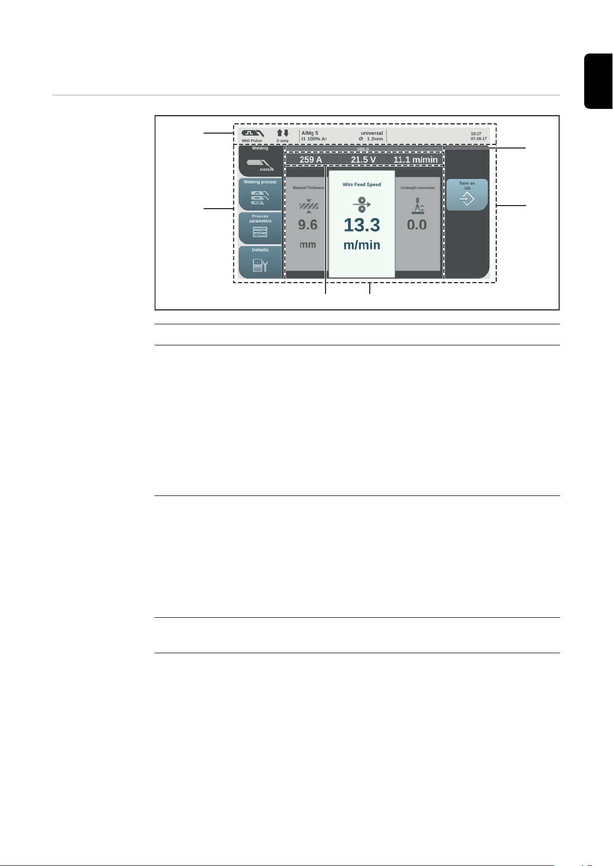
No. Function
(1) Status bar
The status bar provides information on:
- The current welding process
- The current operating mode
- The current welding program (material, shielding gas and wire diameter)
- Active stabilizers and special processes
- Bluetooth status
- Logged-on users / power source locked state
- Active faults
- Time and date
EN
(2) Left-hand ribbon
The left-hand ribbon contains the following buttons:
- Welding
- Welding process
- Process parameters
- Defaults
The buttons in the left-hand ribbon are actuated by touching the display.
(3) Actual value display
Welding current, welding voltage, wire speed
(4) Main area
The welding parameters, graphics, lists or navigation elements are shown in the
main area. The structure of the main area and the elements shown in it vary
according to the application.
The main area is operated
- using the adjusting dial,
- by touching the display.
49
Page 50

Status bar
(1) (2) (3)
(7)(6)(5)(4)
(5) Right-hand ribbon
Depending on the button selected in the left-hand ribbon, the right-hand ribbon
may be used as follows:
- as a function ribbon containing application and function buttons
- for navigating through the 2nd menu level
The buttons in the right-hand ribbon are actuated by touching the display.
(6) HOLD indicator
At the end of each welding operation, the actual values for the welding current
and welding voltage are stored - HOLD lights up.
The status bar is divided into segments and contains the following information:
(1) Current welding process
(2) Current operating mode
(3) Current welding program (material, shielding gas, characteristic and wire dia-
meter)
(4) Stabilizers/CMT Cycle Step active indicator
Arc lengths
Penetration stabilizer
CMT Cycle Step (only in combination with the CMT welding process)
Symbol lights up green:
Stabilizer/CMT Cycle Step is active
Symbol is grey:
Stabilizer/CMT Cycle Step is available, but is not being used for welding
(5) Bluetooth status indicator (certified devices only)
or
(6) Current logged-on user (with active user management)
50
intermediate arc indicator
or
Page 51
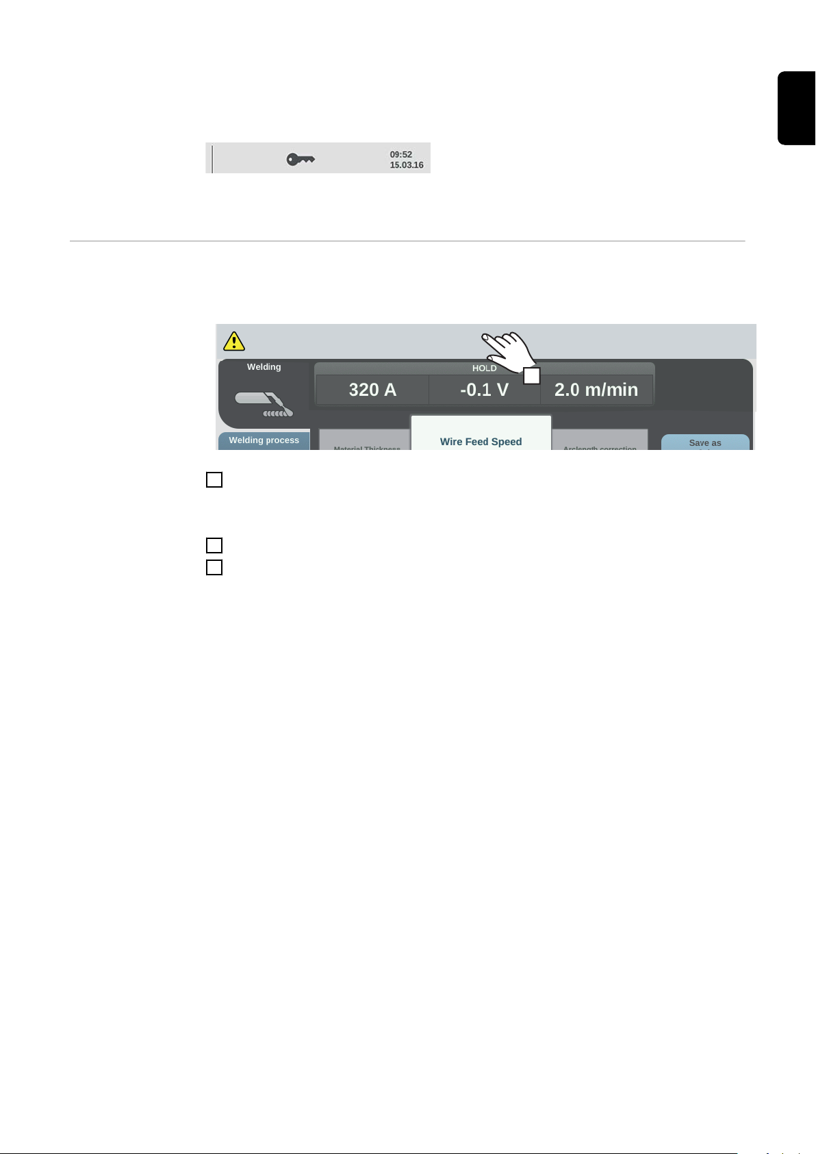
the key symbol when the power source is locked (e.g. when the "locked" profile/
Current limit exceeded!
1
role is active)
(7) Time and date
EN
Status bar – Current limit reached
If the characteristic-dependent current limit is reached while MIG/MAG welding, a corresponding message appears in the status bar.
For detailed information, select the status bar
1
The information appears.
Select "Hide information" to exit
2
Reduce the wire speed, welding current, welding voltage or material thickness
3
or
Increase the distance between the contact tip and the workpiece
Further information on the current limit can be found in the Troubleshooting section on
page 225
51
Page 52

52
Page 53

Installation and commissioning
53
Page 54

54
Page 55

Minimum equipment needed for welding task
General Depending on which welding process you intend to use, a certain minimum equipment
level will be needed in order to work with the power source.
The welding processes and the minimum equipment levels required for the welding task
are then described.
EN
MIG/MAG gascooled welding
MIG/MAG watercooled welding
Manual CMT
welding
- Power source
- Grounding (earthing) cable
- MIG/MAG welding torch, gas-cooled
- Shielding gas supply
- Wire electrode
- Power source
- Cooling unit
- Grounding (earthing) cable
- MIG/MAG welding torch, water-cooled
- Shielding gas supply
- Wire electrode
- Power source
- Standard, Pulse and CMT welding packages enabled on the power source
- Grounding cable
- PullMig CMT welding torch incl. CMT drive unit and CMT wire buffer
IMPORTANT! For water-cooled CMT applications, a cooling unit is also required!
- OPT/i PushPull
- CMT interconnecting hosepack
- Wire electrode
- Gas connection (shielding gas supply)
TIG DC welding - Power source
- Grounding (earthing) cable
- TIG gas-valve torch
- Gas connection (shielding gas supply)
- Filler metal (depending on the application)
MMA welding - Power source
- Grounding (earthing) cable
- Electrode holder with welding cable
- Rod electrodes
55
Page 56

Before installation and commissioning
Safety
Danger from incorrect operation.
Possible serious injury and damage to property.
▶
▶
Proper use The power source may only be used for MIG/MAG, MMA and TIG welding. Any use
above and beyond this purpose is deemed improper. The manufacturer shall not be held
liable for any damage arising from such usage.
Proper use also includes:
- following all the information in the operating instructions
- carrying out all the specified inspection and servicing work
Setup regulations The device is tested to IP 23 protection, meaning:
- protection against penetration by solid foreign bodies with diameters > 12.5 mm
- protection against direct sprays of water at any angle up to 60° from the vertical
WARNING!
Do not use the functions described here until you have read and completely understood these Operating Instructions.
Do not use the functions described here until you have fully read and understood all
of the Operating Instructions for the system components, in particular the safety
rules!
(0.49 in.)
The device can be set up and operated outdoors in accordance with IP23. Avoid direct
wetting (e.g. from rain).
WARNING!
If one of these devices topples over or falls it could cause serious or even fatal
injury.
Place devices, upright consoles and trolleys on a solid, level surface in such a way
▶
that they remain stable.
The venting duct is a very important safety feature. When choosing the installation location, ensure that the cooling air can enter and exit unhindered through the air ducts on
the front and back of the device. Any electroconductive metallic dust (e.g. from grinding
work) must not be allowed to get sucked into the device.
Mains connection - The devices are designed for the mains voltage specified on the rating plate.
- Devices with a nominal voltage of 3 x 575 V must be operated on three-phase systems with earthed star point.
- If your version of the appliance does not come with mains cables and mains plugs
ready-fitted, these must be fitted by a qualified person in accordance with national
standards.
- The fuse protection for the mains lead is indicated in the technical data.
56
Page 57

CAUTION!
Generatorpowered operation
An inadequately dimensioned electrical installation can cause serious damage.
The mains lead and its fuse protection must be dimensioned to suit the local power
▶
supply.
The technical data shown on the rating plate applies.
The power source is generator-compatible.
The maximum apparent power S
of the power source must be known in order to
1max
select the correct generator output.
The maximum apparent power S
of the power source is calculated for 3-phase
1max
devices as follows:
S
= I
1max
See device rating plate or technical data for I
The generator apparent power S
1max
x U1 x √3
and U1 values
1max
needed is calculated using the following rule of
GEN
thumb:
S
GEN
= S
1max
x 1.35
EN
Information on
system components
A smaller generator may be used when not welding at full power.
IMPORTANT! The generator apparent power S
imum apparent power S
of the power source.
1max
must always be higher than the max-
GEN
NOTE!
The voltage delivered by the generator must never exceed the upper or lower limits of the mains voltage tolerance range.
Details of the mains voltage tolerance can be found in the "Technical data" section.
The steps and activities described below include references to various system components, including:
- Trolleys
- Cooling units
- Wire-feed unit holders
- Wire-feed units
- Interconnecting hosepacks
- Welding torches
- etc.
For more detailed information about installing and connecting the system components,
please refer to the appropriate operating instructions.
57
Page 58

Connecting the mains cable
General If no mains cable is connected, a mains cable that is suitable for the connection voltage
must be fitted before commissioning.
A universal strain-relief device for cable diameters from 12 - 30 mm (0.47 - 1.18 in.) is
fitted to the power source.
Strain-relief devices for other cable cross-sections must be designed accordingly.
Stipulated mains
cables
Safety
Power source
Mains voltage: USA & Canada * | Europe
TPS 320i C /nc
3 x 380 V, 3 x 400 V, 3 x 460 V: AWG 14 | 4G 2.5 mm²
TPS 320i C /MV/nc
3 x 200 V, 3 x 230 V: AWG 10 | 4G 4.0 mm²
3 x 380 V, 3 x 400 V, 3 x 460 V: AWG 14 | 4G 2.5 mm²
TPS 320i C /S/nc **
3 x 460 V, 3 x 575 V: AWG 14 | -
* Cable type for USA / Canada: Extra-hard usage
** Power source without CE mark; not available in Europe
AWG = American wire gauge
WARNING!
Danger due to work that has been carried out incorrectly.
This can result in serious injury and damage to property.
The work described below must only be carried out by trained and qualified person-
▶
nel.
Observe national standards and directives.
▶
Connecting the
mains cable general
58
CAUTION!
Danger due to improperly prepared mains cable.
This can cause short circuits and damage.
Fit ferrules to all phase conductors and the ground conductor of the stripped mains
▶
cable.
IMPORTANT! The ground conductor should be approx. 20 - 25 mm (0.8 - 1 in.) longer
than the phase conductors.
Page 59

1 2
3
EN
4
Tightening torque = 1.2 Nm
(TPS 320i C, TPS 320i C /nc,
TPS 320i C /S/nc)
Tightening torque = 3.5 Nm
(TPS 320i C /MV/nc)
59
Page 60

5
2
1
3
4
5
6
1
2
3
5
4
6
Phase conductor:
Tightening torque = 1.5 Nm, TX 15
(TPS 320i C, TPS 320i C /nc,
TPS 320i C /S/nc)
Tightening torque = 1.5 Nm, TX 25
(TPS 320i C /MV/nc)
Ground conductor:
Tightening torque = 1.2 Nm
6
5 x TX25
Tightening torque = 3 Nm
7
60
Page 61

Commissioning the TPS 320i C
EN
Safety
An electric shock can be fatal.
If the power source is connected to the mains electricity supply during installation, there
is a high risk of very serious injury and damage.
▶
▶
Danger from electrical current due to electrically conductive dust in the device.
This can result in serious injury and damage to property.
▶
General Commissioning the TPS 320i C power source is described by reference to a manual gas-
cooled MIG/MAG application.
WARNING!
Before carrying out any work on the device make sure that the power source mains
switch is in the "O" position
Before carrying out any work on the device make sure that the power source is
unplugged from the mains
WARNING!
Only operate the device with an air filter fitted. The air filter is a very important safety
device for adhering to the IP 23 protection class.
Recommendation
for water-cooled
applications
Connecting the
gas cylinder
- Use a PickUp 5000 trolley
- Fit the cooling unit to the PickUp 5000 trolley
- Fit the TPS 320i C power source to the cooling unit
- Use only water-cooled welding torches with an external water connection
- Connect the water connections on the welding torch directly to the cooling unit
WARNING!
There is a high risk of very serious injury and damage if a gas cylinder falls over.
Place gas cylinders on a solid, level surface so that they remain stable. Secure gas
▶
cylinders to prevent them from toppling over.
Observe the safety rules of the gas cylinder manufacturer.
▶
61
Page 62

Connecting the gas hose to the TPS 320i C
Place the gas cylinder on a solid, level
1
surface in such a way that it remains
stable
Secure the gas cylinder to prevent it
2
from toppling over (but not around the
neck of the cylinder)
Take the protective cap off the gas cyl-
3
inder
Briefly open the gas cylinder valve to
4
remove any dust or dirt
Check the seal on the pressure regu-
5
lator
Screw the pressure regulator onto the
6
gas cylinder and tighten it
Connect the pressure regulator to the
7
shielding gas connection on the power
source using the gas hose
Establishing a
ground earth
connection
NOTE!
When establishing a ground earth connection, observe the following points:
Use a separate grounding cable for each power source
▶
Keep the plus cable and grounding cable together as long and as close as possible
▶
Physically separate the welding circuits of individual power sources
▶
Do not route several grounding cables in parallel;
▶
if parallel routing cannot be avoided, keep a minimum distance of 30 cm between
the welding circuits
Keep the grounding cable as short as possible, provide a large cable cross-section
▶
Do not cross grounding cables
▶
Avoid ferromagnetic materials between the grounding cable and the interconnecting
▶
hosepack
Do not wind up long grounding cables - coil effect!
▶
Lay long grounding cables in loops
Do not route grounding cables in iron pipes, metal cable conduits or on steel rails,
▶
avoid cable ducts;
(routing of plus cables and grounding cables together in an iron pipe does not cause
any problems)
If there are several grounding cables, separating the grounding points on the com-
▶
ponent so that they are as far away from one another as possible is recommended,
as well as preventing crossed current paths from occurring underneath the individual
arcs.
Use compensated interconnecting hosepacks (interconnecting hosepacks with
▶
integrated grounding cable)
62
Page 63

Plug the grounding cable into the (-)
1
current socket
Lock the grounding cable in place
2
Use the other end of the grounding
3
cable to establish a connection to the
workpiece
Connecting the grounding cable to the TPS 320i C
CAUTION!
A shared ground earth connection for multiple power sources will have an adverse
effect on welding results!
If multiple power sources are being used to weld a component, a shared ground earth
connection can have a massive impact on the welding results.
Separate the welding circuits!
▶
Provide a different ground earth connection for each welding circuit!
▶
Do not use a single, shared earth (ground) lead!
▶
EN
Connecting the
welding torch
Inserting/replacing feed rollers
Before connecting the welding torch, check that all cables, lines and hosepacks are
1
undamaged and properly insulated.
2
In order to achieve optimum wire electrode feed, the feed rollers must be suitable for the
diameter and alloy of the wire being welded.
63
Page 64

NOTE!
Only use feed rollers that match the wire electrode.
An overview of the feed rollers available and their potential application areas can be
found in the Spare Parts Lists.
CAUTION!
Risk of injury if the feed roller holders fly upwards.
When unlocking the lever, keep fingers away from the area to the left and right of the
▶
lever.
1 2
Inserting the
wirespool
3 4
CAUTION!
Risk of injury due to springiness of spooled wire electrode.
While inserting the wirespool, hold the end of the wire electrode firmly to avoid injur-
▶
ies caused by the wire electrode springing back.
64
CAUTION!
Risk of injury from falling wirespool.
Make sure that the wirespool is fitted securely to the wirespool holder.
▶
Page 65
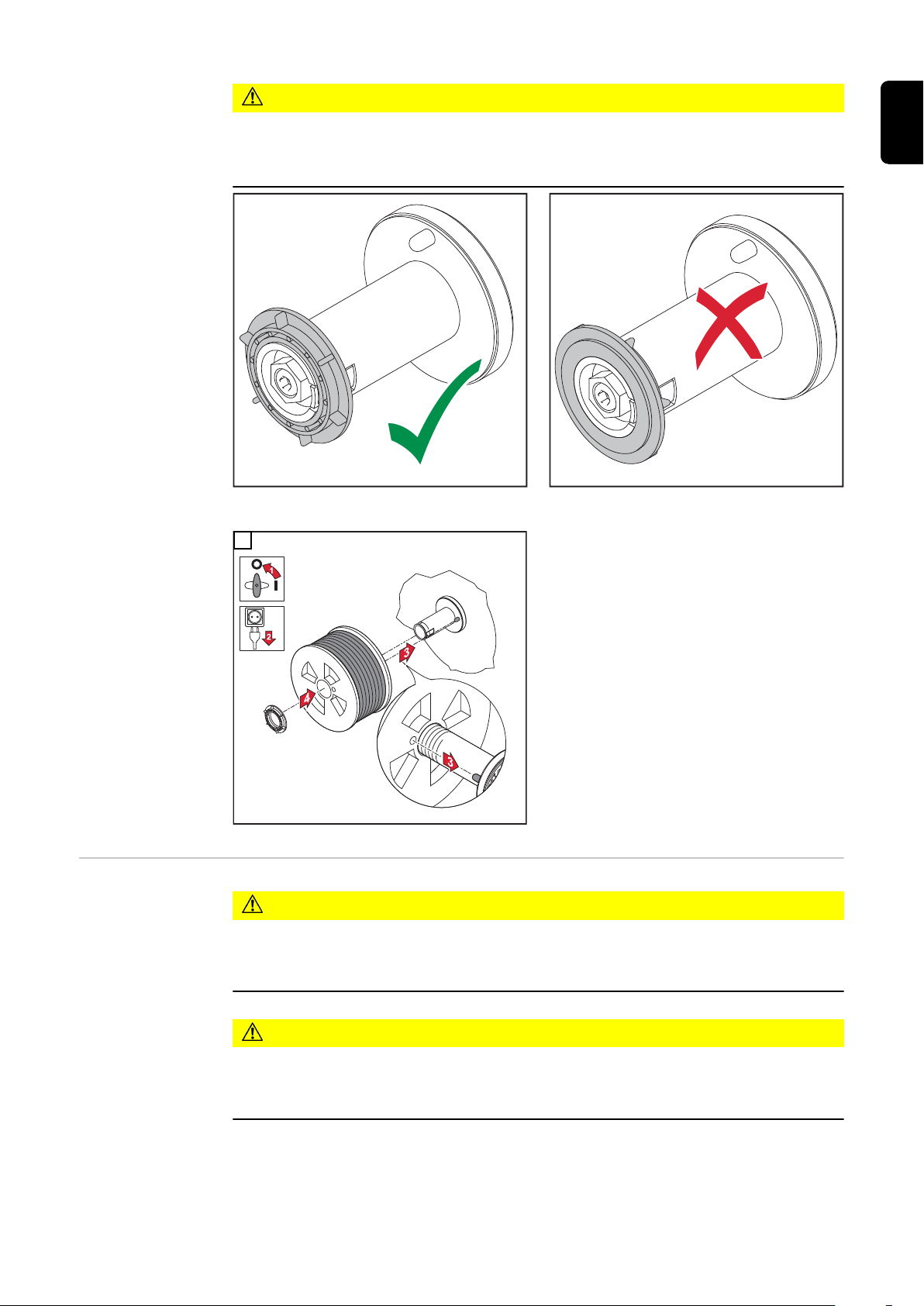
CAUTION!
Risk of injury and impaired performance if the wirespool topples over because the
locking ring has been placed the wrong way round.
Always position the locking ring as shown in the diagram on the left.
▶
1
EN
Inserting the basket-type spool
CAUTION!
Risk of injury due to springiness of spooled wire electrode.
While inserting the basket-type spool, hold the end of the wire electrode firmly to
▶
avoid injuries caused by the wire electrode springing back.
CAUTION!
Risk of injury from falling basket-type spool.
Make sure that the basket-type spool and basket-type spool adapter are fitted
▶
securely to the wirespool holder.
65
Page 66

NOTE!
When working with basket-type spools, only use the basket-type spool adapter
included in the scope of supply.
CAUTION!
Risk of injury from falling basket-type spool.
Place the basket-type spool on the adapter provided in such a way that the bars on
▶
the spool are inside the adapter guideways.
CAUTION!
Risk of injury and impaired performance if the basket-type spool topples over
because the locking ring has been placed the wrong way round.
Always position the locking ring as shown in the diagram on the left.
▶
1 2
66
Page 67

Feeding in the
1
2
4
5
3
1
1
2
3
wire electrode
CAUTION!
Risk of injury due to springiness of spooled wire electrode.
To avoid injuries caused by the wire electrode springing back:
When inserting the wire electrode into the 4-roller drive, hold the end of the wire
▶
electrode firmly.
CAUTION!
Risk of damage to the welding torch from sharp end of wire electrode.
Deburr the end of the wire electrode well before threading in.
▶
Lay the welding torch hosepack as straight as possible.
▶
1 2
EN
CAUTION!
Risk of injury and damage from electric shock and from the wire electrode emerging from the torch.
Keep the welding torch away from the face and body when pressing the torch trigger
▶
or feeder inching button.
Do not point the welding torch at people
▶
Make sure that the wire electrode does not touch any conductive or earthed (groun-
▶
ded) parts (e.g. the housing, etc.) when pressing the torch trigger
3
4
67
Page 68

Setting the con-
4
3
STOP
6
7
5
1
2
2
1
tact pressure
NOTE!
Set the contact pressure in such a way that the wire electrode is not deformed but
nevertheless ensures proper wirefeeding.
Adjusting the
brake
1
Contact pressure standard values for
U-groove rollers
Steel:
4 - 5
CrNi
4 - 5
Tubular cored electrodes
2 - 3
NOTE!
After releasing the torch trigger the wirespool should stop unreeling.
Adjust brake if necessary.
1
2
68
Page 69

2
1
4
STOP
OK
3
3
EN
Design of the
brake
Performing R/L
alignment
WARNING!
Danger from incorrect installation.
This can result in severe personal injury
and damage to property.
Do not dismantle the brake.
▶
Maintenance and servicing of brakes
▶
is to be carried out by trained, qualified personnel only.
The brake is only available as a complete
unit.
This illustration is for information purposes
only.
IMPORTANT! For optimum welding results, the manufacturer recommends performing
an R/L alignment when starting the device for the first time and when any changes are
made to the welding system.
More information about the R/L alignment can be found under "R/L alignment" in the
"Process parameters" section of the "Welding mode" chapter (page 129).
69
Page 70

Locking and unlocking the power source using the
NFC key
General remarks NFC key = NFC card or NFC key ring
The power source can be locked using an NFC key, e.g. to prevent unauthorised access
or welding parameters being changed without permission.
A contactless system on the control panel allows the power source to be locked and
unlocked.
The power source must be switched on before it can be locked or unlocked.
Locking and
unlocking the
power source
using the NFC
key
Locking the power source
Hold the NFC key on the NFC key reader
1
The key symbol appears on the display.
The key symbol is then displayed in the status bar.
70
Page 71

universal
The power source is now locked.
Only the welding parameters can be viewed and adjusted using the adjusting dial.
Any attempt to call a locked function will result in a notification being displayed.
Unlocking the power source
EN
Hold the NFC key on the NFC key reader
1
The crossed-out key symbol appears on the display.
The key symbol no longer appears in the status bar.
All power source functions are now available again without restrictions.
NOTE!
More information about locking and unlocking the power source can be found in
the "Defaults - Management / Administration" section from page 180.
71
Page 72

72
Page 73

Welding
73
Page 74

74
Page 75

MIG/MAG modes
S
E
EN
General
Symbols and
their explanations
WARNING!
Danger from incorrect operation.
Possible serious injury and damage to property.
Do not use the functions described here until you have read and completely under-
▶
stood these Operating Instructions.
Do not use the functions described here until you have fully read and understood all
▶
of the Operating Instructions for the system components, in particular the safety
rules!
See the Setup menu for information on settings, setting range and units of measurement
for the available parameters.
Press the torch trigger | Hold the torch trigger | Release the torch trigger
GPr
Gas pre-flow
I-S
Starting-current phase: the base material is heated up rapidly, despite the high thermal
dissipation that occurs at the start of welding
t-S
Starting current time
Start arc length correction
SL1
Slope 1: the starting current is steadily lowered until it reaches the welding current
I
Welding-current phase: uniform thermal input into the base material, whose temperature
is raised by the advancing heat
I-E
Final current phase: to prevent any local overheating of the base material due to heat
build-up towards the end of welding. This eliminates any risk of weld seam drop-through.
t-E
Final current time
End arc length correction
75
Page 76

2-step mode
t
I
+
I
GPr
GPo
t
I
+
I
GPr GPo
+
SL2
Slope 2: the welding current is steadily lowered until it reaches the final current
GPo
Gas post-flow
A detailed explanation of the parameters can be found in the section headed "Process
parameters"
4-step mode
"2-step mode" is suitable for
- Tacking work
- Short weld seams
- Automated and robot welding
"4-step mode" is suitable for longer weld seams.
76
Page 77

Special 4-step
I
t
I
GPr GPo
I-E
SL1t-S
I-S
SL2
+ +
S
E
t-E
I
I-S
I-E
+
I
S
E
GPr GPoSL1 SL2
t
t-S t-E
mode
Special 2-step
mode
EN
"Special 4-step mode" is particularly suitable for welding aluminium materials. The special slope of the welding current curve takes account of the high thermal conductivity of
aluminium.
"Special 2-step mode" is ideal for welding in the higher power range. In special 2-step
mode, the arc starts at a lower power, which makes it easier to stabilise.
77
Page 78

Spot welding
I
+
I
GPr GPoSPt
t
The "Spot welding" mode is suitable for welded joints on overlapped sheets.
78
Page 79

MIG/MAG and CMT welding
EN
Safety
MIG/MAG and
CMT welding –
overview
WARNING!
Danger from incorrect operation.
Possible serious injury and damage to property.
Do not use the functions described here until you have read and completely under-
▶
stood these Operating Instructions.
Do not use the functions described here until you have fully read and understood all
▶
of the Operating Instructions for the system components, in particular the safety
rules!
WARNING!
An electric shock can be fatal.
If the power source is connected to the mains electricity supply during installation, there
is a high risk of very serious injury and damage.
Before carrying out any work on the device make sure that the power source mains
▶
switch is in the "O" position
Before carrying out any work on the device make sure that the power source is
▶
unplugged from the mains
The "MIG/MAG and CMT welding" section comprises the following steps:
- Switching on the power source
- Selecting the welding process and operating mode
- Selecting the filler metal and shielding gas
- Setting the welding and process parameters
- Setting the shielding gas flow rate
- MIG/MAG or CMT welding
Switching on the
power source
NOTE!
If using a cooling unit, follow the safety rules and note the operating conditions in
the cooling unit Operating Instructions.
Connect the mains cable
1
Move the mains switch to the "I" position
2
A cooling unit connected to the system will begin to operate.
IMPORTANT! For optimum welding results, the manufacturer recommends performing
an R/L alignment when starting the device for the first time and when any changes are
made to the welding system.
More information about the R/L alignment can be found under "R/L alignment" in the
"Process parameters" section of the "Welding mode" chapter (page 129).
79
Page 80

Setting the weld-
2
3
1
*
5
4
4-step
ing process and
operating mode
Setting the welding process
* next page: Electrode, TIG
Select "Welding process"
1
Select "Process"
2
An overview of the welding process is displayed.
Various welding processes are available depending on the power source type or function
package installed.
Select the desired welding process
3
Setting the operating mode
80
Select "Mode"
4
An overview of the operating modes is displayed:
Page 81

Selecting the
1
2
3
filler metal and
shielding gas
- 2-step mode
- 4-step mode
- Special 2-step mode
- Special 4-step mode
Select the desired operating mode
5
EN
Select "Welding process"
1
Select "Filler metal"
2
Select "Change material settings"
3
Turn the adjusting dial and select the desired filler metal
4
Select "Next" / press the adjusting dial
5
Turn the adjusting dial and select the desired wire diameter
6
Select "Next" / press the adjusting dial
7
Turn the adjusting dial and select the desired shielding gas
8
Select "Next" / press the adjusting dial
9
NOTE!
The available characteristics per welding process are not displayed if only one
characteristic is available for the selected filler metal.
In this case, the confirmation step of the filler metal wizard follows immediately; steps 10
- 14 do not apply.
Turn the adjusting dial and select the desired welding process
10
To select the desired characteristic, press the adjusting dial (blue background)
11
Turn the adjusting dial and select the desired characteristic
12
Press the adjusting dial and apply the selected characteristic (white background)
13
Select "Next"
14
The confirmation step of the filler metal wizard is displayed:
81
Page 82
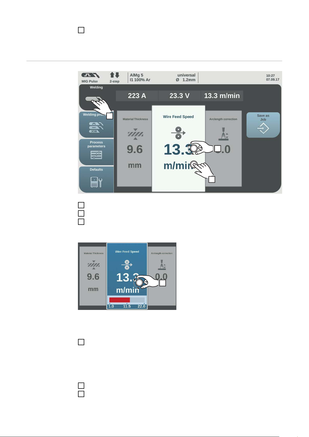
Setting the weld-
1
2
3
4
ing parameters
Select "Save" / press the adjusting dial
15
The selected filler metal and associated characteristics per welding process will be
saved.
Select "Welding"
1
Select the desired welding parameter by turning the adjusting dial
2
Press the adjusting dial to change the welding parameter
3
The value of the welding parameter is displayed as a horizontal scale:
e.g. wire speed parameter
The value of the selected parameter can now be changed.
Turn the adjusting dial to change the welding parameter
4
The adjusted value of the welding parameter is applied immediately.
If one of the "Wire speed", "Material thickness", "Current" or "Voltage" parameters is
changed during synergic welding, the other welding parameters are immediately adjusted accordingly.
82
Press the adjusting dial to call up the welding parameters overview
5
Adjust the process parameters accordingly to make user- or application-specific set-
6
tings on the welding system
Page 83

Setting the
1
shielding gas
flow rate
MIG/MAG or CMT
welding
Open the gas cylinder valve
1
Press the gas test button
2
Shielding gas flows out
Turn the adjusting screw on the underside of the pressure regulator until the pres-
3
sure gauge shows the required shielding gas flow rate
Press the gas test button
4
The flow of gas stops.
EN
Select "Welding" to display the welding parameters
1
CAUTION!
Risk of injury and damage from electric shock and from the wire electrode emerging from the torch.
When pressing the torch trigger:
keep the torch away from your face and body
▶
do not point the welding torch at people
▶
make sure that the wire electrode does not touch any electrically conducting or
▶
earthed (grounded) parts, such as the housing, etc.
Press the torch trigger and start welding
2
Whenever welding ends, the actual values for the welding current, welding voltage and
wire speed are stored, and HOLD appears on the display.
NOTE!
Parameters that have been set on a system component control panel (e.g. wire
feed unit or remote control) might not be able to be changed on the power source
control panel.
83
Page 84

MIG/MAG and CMT welding parameters
Welding parameters for MIG/MAG
pulse synergic
welding, for CMT
welding and PMC
welding
The following welding parameters for MIG/MAG pulse synergic welding, CMT welding
and PMC welding can be set and displayed by pressing the "Welding" button:
Current 1) [A]
Setting range: depends on the welding process and welding program selected
Before the start of welding, the machine automatically displays a standard value based
on the programmed parameters. The actual value is displayed during welding.
Voltage 1) [V]
Setting range: depends on the welding process and welding program selected
Before the start of welding, the machine automatically displays a standard value based
on the programmed parameters. The actual value is displayed during welding.
Material thickness
0.1 - 30.0 mm 2) / 0.004 - 1.18 2) in.
Wire speed
0.5 - max.
1)
2) 3)
1)
m/min / 19.69 - max
2) 3)
ipm.
Arc length correction
for correcting the arc length;
-10 - +10
Factory setting: 0
- .... shorter arc length
0 ... neutral arc length
+ ... longer arc length
Pulse/dynamic correction
for correcting the pulsing energy of a pulsed arc
-10 - +10
Factory setting: 0
- ... lower droplet detachment force
0 ... neutral droplet detachment force
+ ... increased droplet detachment force
84
Page 85

Welding parameters for MIG/MAG
standard synergic welding and
LSC welding
The following welding parameters for MIG/MAG standard synergic welding and LSC
welding can be set and displayed by selecting the "Welding" menu button:
Current 1) [A]
Setting range: depends on the welding process and welding program selected
Before the start of welding, the machine automatically displays a standard value based
on the programmed parameters. The actual value is displayed during welding.
Voltage 1) [V]
Setting range: depends on the welding process and welding program selected
Before the start of welding, the machine automatically displays a standard value based
on the programmed parameters. The actual value is displayed during welding.
EN
Material thickness
1)
0.1 - 30.0 mm 2) / 0.004 - 1.18 2) in.
Wire speed
0.5 - max.
1)
2) 3)
m/min / 19.69 - max
2) 3)
ipm.
Arc length correction
for correcting the arc length;
-10 - +10
Factory setting: 0
- .... shorter arc length
0 ... neutral arc length
+ ... longer arc length
Pulse/dynamic correction
for correcting the pulsing energy of a pulsed arc
-10 - +10
Factory setting: 0
- ... lower droplet detachment force
0 ... neutral droplet detachment force
+ ... increased droplet detachment force
85
Page 86

Welding parameters for MIG/MAG
standard manual
welding
The following welding parameters for MIG/MAG standard manual welding can be set and
displayed by selecting the "Welding" menu button:
Voltage 1) [V]
Setting range: depends on the welding process and welding program selected
Before the start of welding, the machine automatically displays a standard value based
on the programmed parameters. The actual value is displayed during welding.
Arc-force dynamic
to influence the short-circuiting dynamic at the instant of droplet transfer
0 - 10
Factory setting: 0
0 ... harder and more stable arc
10 ... soft and low-spatter arc
Explanation of
footnotes
Wire speed
1)
for setting a harder, more stable arc
0.5 - max. 2) m/min / 19.69 - max 2) ipm.
1) Synergic parameter
When a synergic parameter is changed, the synergic function automatically
changes all other synergic parameters to match.
The real setting range depends on power source and wire feeder used and on
the welding programm.
2) The real setting range depends on the welding program.
3) The maximum value depends on the wire feeder used.
86
Page 87
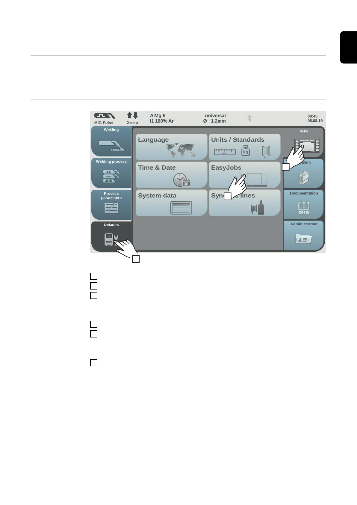
EasyJob mode
3
1
2
General If EasyJob mode has been activated, 5 additional buttons appear on the display. These
enable up to 5 operating points to be saved at the touch of a button.
The current welding settings are saved.
Activating EasyJob mode
EN
Select "Defaults"
1
Select "View"
2
Select "EasyJobs"
3
The overview to activate/deactivate EasyJob mode is displayed.
Select "EasyJobs on"
4
Select "OK"
5
EasyJob mode is activated and the default settings are displayed.
Select "Welding"
6
Five "EasyJob" buttons are displayed for the welding parameters.
87
Page 88

Storing EasyJob
1
~ 3 sec.
1
< 3 sec.
operating points
NOTE!
The EasyJobs are stored under job numbers 1 - 5 and can also be retrieved using
"Job mode".
Storing an EasyJob overwrites any other job saved under the same number!
To store the current welding settings, touch one of the EasyJob buttons for about
1
three seconds
The size and colour of the button changes. After about three seconds, the button is displayed green with a frame.
The settings have now been stored. The most recently stored settings will be active. An
active EasyJob is displayed with a tick on the EasyJob button.
Unused EasyJob buttons are displayed in dark grey.
Retrieving EasyJob operating
points
To retrieve a saved EasyJob operating point, touch the corresponding EasyJob but-
1
ton briefly (< 3 seconds)
The size and colour of the button changes briefly; it is then displayed with a tick.
If a tick is not displayed after touching an EasyJob button, this means that there is no
operating point saved under this button.
88
Page 89

Deleting EasyJob
1
> 5 sec.
*
operating points
To delete an EasyJob operating point, touch the relevant EasyJob button for approx-
1
imately 5 seconds
The button
- First changes its size and colour;
- Is displayed with a frame after about 3 seconds;
The saved operating point is overwritten with the current settings.
- Is highlighted in red (= delete) after a total of 5 seconds.
The EasyJob operating point has been deleted.
EN
* ... highlighted in red
89
Page 90

Job mode
2
General Up to 1000 jobs can be stored and retrieved in the power source.
This eliminates the need for manual documenting of the welding parameters.
"Job mode" enhances the quality of automated and manual applications.
Jobs can only be stored when in welding mode. When storing jobs, the process parameters and certain machine defaults are taken into account in addition to the present welding settings.
Storing settings
as a job
Set the parameters that are to be stored as a job:
1
- Welding parameters
- Welding process
- Process parameters
- Machine defaults (if necessary)
90
Select "Save as Job"
2
The job list is displayed.
To overwrite an existing job, select it by turning and pressing the adjusting dial (or selecting "Next").
The selected job can be overwritten after acknowledging the confirmation prompt.
Select "Create a new Job" to create a new job
Press the adjusting dial / select "Next"
3
The next free job number is displayed.
Turn the adjusting dial and select the desired storage location
4
Press the adjusting dial / select "Next"
5
The keyboard is displayed.
Page 91

Enter a job name
3
1
2
6
Select "OK" and confirm the job name / press the adjusting dial
7
The name is saved and a confirmation that the job has been stored is displayed.
To exit, select "Finish" / press the adjusting dial
8
EN
Job welding retrieving a job
NOTE!
Before retrieving a job, make sure that the welding system has been installed and
set up for the job.
Select "Welding process"
1
Select "Process"
2
Select "Job mode"
3
Job mode is activated.
"Job welding" and the data from the most recently retrieved job are displayed.
Select "Job welding"
4
Turn the adjusting dial and select "Job number" (white background)
5
To select the desired job, press the adjusting dial (blue background)
6
Turn the adjusting dial to select the desired job number (blue background)
7
The name of the selected job is displayed above the actual value display.
Press the adjusting dial and accept the selected job number (white background)
8
Start welding
9
IMPORTANT! "Job number" is the only parameter that can be altered in Job mode; all
the others are read-only.
91
Page 92

Renaming a job
1
2
3
universal
Select "Save as Job"
1
(also works in Job mode)
The job list is displayed.
92
Turn the adjusting dial and select the job to be renamed
2
Select "Rename Job"
3
The keyboard is displayed.
Change the job name using the keyboard
4
Select "OK" and confirm the amended job name / press the adjusting dial
5
The job name is changed and the job list is displayed.
To exit, select "Cancel"
6
Page 93

Deleting a job
1
2
3
universal
Select "Save as Job"
1
(also works in Job mode)
The job list is displayed.
EN
Turn the adjusting dial and select the job to be deleted
2
Select "Delete Job"
3
A confirmation prompt asking whether you really want to delete the job is displayed.
Select "Yes" to delete the selected job
4
The job is deleted, the job list is displayed.
To exit, select "Cancel"
5
93
Page 94

Loading a job The load job function can be used to load the data for a saved job or an EasyJob to the
1
universal
welding screen. The relevant data from the job is displayed in the welding parameters
and can be changed, saved as a new job or EasyJob, or used to start welding.
Select "Save as Job"
1
(also works in Job mode)
The job list is displayed.
Turn the adjusting dial and select the job to be loaded
2
Select "load Job"
3
The load job information is shown.
Select "Yes"
4
The data for the selected job is loaded onto the welding screen.
The data for the loaded job can now be used for welding (no job mode), changed, or be
saved as a new job or an EasyJob.
94
Page 95

Optimize job
2
1
*
3
* Only displayed if the OPT/i CMT Cycle Step option is present on the power source. In TWIN mode, the TWIN
process control button is displayed after the "Process mix" button.
Select "Process parameters"
1
Select "JOB"
2
EN
An overview of the job functions is displayed.
Select "Optimize Job"
3
The overview of the most recently optimised job is displayed.
95
Page 96
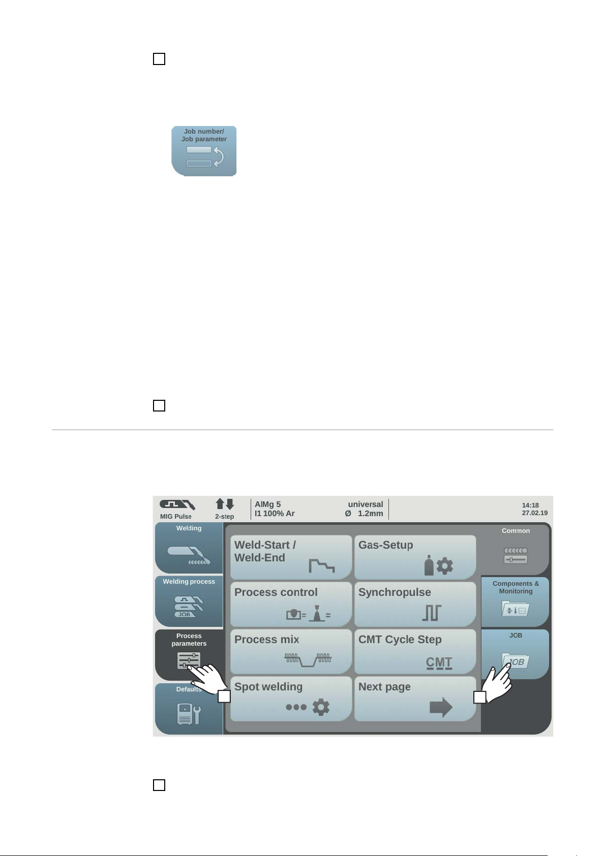
Turn the adjusting dial and select either the job or the job welding parameters to be
2
1
*
4
modified
The choice between the job and the job welding parameters can also be made by
touching the "Job number / Job parameter" button.
Select job:
- Press the adjusting dial
The job number is highlighted in blue and can now be changed.
- Turn the adjusting dial to select the job to be altered
- Press the adjusting dial to change the job
Select job welding parameters:
- Turn the adjusting dial and select the parameter to be changed
- Press the adjusting dial
The value of the parameter is highlighted in blue and can now be changed.
Setting correction limits for a
job
- Turn the adjusting dial; the amended value is applied immediately
- Press the adjusting dial to select other parameters
Select "Finish"
5
Individual correction limits for welding power and arc length can be defined for each job.
If correction limits are defined for a job, the welding power and arc length for the job in
question can be corrected within the defined limits while welding.
96
* Only displayed if the OPT/i CMT Cycle Step option is present on the power source. In TWIN mode, the TWIN
process control button is displayed after the "Process mix" button.
Select "Process parameters"
1
Page 97

Select "JOB"
3
2
An overview of the job functions is displayed.
Select "Correction limits"
3
EN
A list of the job correction limits for the last job opened is displayed.
Turn the adjusting dial and select either the job or the job limits to be modified
4
The choice between the job and the job limits can also be made by touching the "Job
number / Job parameter" button.
Select job:
- Press the adjusting dial
The job number is highlighted in blue and can now be changed.
- Turn the adjusting dial to select the job to be altered
- Press the adjusting dial to change the job
Select job limits:
- Turn the adjusting dial and select the desired limit group
- Press the adjusting dial
The selected limit group opens.
- Turn the adjusting dial and select the top or bottom limit
- Press the adjusting dial
The value of the limit parameter is highlighted in blue and can now be changed.
- Turn the adjusting dial; the amended value is applied immediately
- Press the adjusting dial to select other limit parameters
97
Page 98

Select "Finish"
2
1
*
3
5
Pre-settings for
"Save as Job"
Pre-settings for "Save as Job" are used to set the default values that are assumed for
every newly created job.
* Only displayed if the OPT/i CMT Cycle Step option is present on the power source. In TWIN mode, the TWIN
process control button is displayed after the "Process mix" button.
Select "Process parameters"
1
Select "JOB"
2
An overview of the job functions is displayed.
98
Select "Pre-settings for "Save as Job""
3
Confirm the displayed information
4
The default settings for saving new jobs are displayed.
Page 99

Turn the adjusting dial and select the desired parameter
5
Press the adjusting dial
6
Turn the adjusting dial and change the value
7
Press the adjusting dial
8
Select "Finish"
9
EN
99
Page 100

Spot welding
2
3
1
*
5
4
6
4-step
Spot welding
Select "Welding process"
1
Select "Process"
2
Select the desired welding process
3
100
Select "Mode"
4
Select "Spot welding"
5
Select "Process parameters"
6
 Loading...