

Page 1

/ Battery Charging Systems / Welding Technology / Solar Electronics
Einbauset Heizung Pipe
Pipe heater installation set
Einbauanleitung
DEEN
MIG/MAG-Systemerweiterung
Installation instructions
MIG/MAG-System extension
42,0410,1411 003-12032013
Page 2

Page 3

Inhaltsverzeichnis
Allgemeines ................................................................................................................................................... 2
Funktionsprinzip ....................................................................................................................................... 2
Sicherheit ................................................................................................................................................. 2
Lieferumfang ............................................................................................................................................. 3
Erforderliche Werkzeuge und Hilfsmittel ................................................................................................... 3
Gehäuse öffnen, nicht mehr benötigte Komponenten ausbauen..................................................................... 4
Gehäuse öffnen ......................................................................................................................................... 4
Kabelbaum entfernen ................................................................................................................................5
Montageplatte mit Print RP24-10 abnehmen / Geräte-Rückseite entfernen.............................................. 6
E-Set Heizung einbauen ................................................................................................................................ 7
Allgemeines .............................................................................................................................................. 7
Thermoschalter montieren......................................................................................................................... 7
Trafo montieren ......................................................................................................................................... 7
Stecker an neuer Geräte-Rückseite montieren ........................................................................................ 8
E-Set Heizung einbauen bei Geräten mit einer Seriennummer vor 18031198 ................................................. 9
Allgemeines .............................................................................................................................................. 9
Thermoschalter montieren und Print RP24-10 im Gehäuse befestigen ...................................................... 9
Trafo montieren ........................................................................................................................................ 10
Gehäuseboden für Montage der Heizung 150 W vorbereiten .................................................................... 11
Stecker an neuer Geräte-Rückseite montieren ....................................................................................... 11
E-Set Heizung anschließen ..........................................................................................................................12
Heizungen anschließen ...........................................................................................................................12
DE
Gehäuse schließen / Sicherheitstechnische Überprüfung durchführen ..........................................................14
Gehäuse schließen ................................................................................................................................. 14
Sicherheitstechnische Überprüfung durchführen ......................................................................................14
1
Page 4

2
Page 5

Allgemeines
WARNUNG! Fehlerhaft durchgeführte Arbeiten können schwerwiegende Perso-
nen- und Sachschäden verursachen. Nachfolgend beschriebene Tätigkeiten
dürfen nur von geschultem Fachpersonal durchgeführt werden. Nachfolgend
beschriebene Tätigkeiten erst durchführen, wenn folgende Dokumente vollständig gelesen und verstanden wurden:
- diese Einbauanleitung
- sämtliche Bedienungsanleitungen der Systemkomponenten, insbesondere
Sicherheitsvorschriften
WARNUNG! Ein elektrischer Schlag kann tödlich sein. Vor Öffnen des Gerätes:
- Netzschalter der Stromquelle in Stellung - O - schalten
- Stromquelle vom Netz trennen
- Deutlich lesbares und verständliches Warnschild gegen Wiedereinschalten
anbringen
Mit Hilfe eines geeigneten Messgerätes sicherstellen, dass elektrisch geladene
Bauteile (z.B. Kondensatoren) entladen sind.
DE
Funktionsprinzip
Sicherheit
Um einen Einsatz unter - 10° C (14° F) zu ermöglichen können die Stromquellen mit dem
Einbauset Heizung ausgestattet werden. Die Heizung ist unabhängig vom Geräte-Hauptschalter und erzeugt Wärme sobald die Netzversorgung aufrecht und der HeizungsHauptschalter eingeschaltet ist. Ein Thermoschalter überwacht die Temperatur und
schaltet die Heizung ab, sobald eine Geräte-Innenraumtemperatur von + 15° C (59° F)
errreicht ist.
Die Funktion der Heizung ist bis zu einer Aussentemperatur von -30° C (-22° F) gewährleistet. Bei so tiefen Temperaturen dauert es ca. 60 - 80 Minuten bis die Heizung die
Stromquelle auf Einschalttemperatur gebracht hat.
VORSICHT! Unzureichende Schutzleiter-Verbindung kann schwerwiegende
Personen- und Sachschäden verursachen. Die Gehäuseschrauben stellen
eine geeignete Schutzleiter-Verbindung für die Erdung des Gehäuses dar und
dürfen keinesfalls durch andere Schrauben ohne zuverlässige SchutzleiterVerbindung ersetzt werden.
HINWEIS! Beachten Sie beim Umgang mit elektronischen Bauteilen und Prints
die ESD-Bestimmungen. Dazu gehören vor allem ESD-gerechte
- Verpackungen
- Arbeitsflächen
- Böden
- Sitzgelegenheiten
- Erdungsmöglichkeiten
Für einen unsachgemäß behandelten elektronischen Bauteil oder Print können keine
Garantie- und Gewährleistungsansprüche geltend gemacht werden.
3
Page 6

Lieferumfang Im Lieferumfang des Einbausets Heizung sind folgende Bauteile enthalten:
(1)
(9)
(8)
(2)
(3)
(4)
Lieferumfang
(1) Heizelement 200 W auf Geräte-Rückseite montiert
(2) Teilstück 1 vom Kabelbaum
(3) Heizelement 150 W
(4) Trafo-Montageblech
(5) Trafo für 230 V Versorgung der Heizelemente
(6) In Plastiktüte verpackt:
- 1 Stück Reserve Schmelzsicherung 2 A träge 6,3 x 32
- 10 Stück Taptite-Schrauben M5 x 10 mm
- 1 Stück Thermoschalter
- 2 Stück Linsenblech-Schrauben 3,5 x 9,5 mm
- 4 Stück Linsenkopf-Schrauben M3 x 10 mm
- 4 Stück Sk-Mutter M 3
- 4 Stück Beilagscheiben A 3,2
- 1 Stück Sk-Mutter M5
(7) Teilstück 2 vom Kabelbaum
(8) Teilstück 3 vom Kabelbaum
(9) Kabelbinder
(7)
(6)
(5)
Erforderliche
Werkzeuge und
Hilfsmittel
1 x Seitenschneider
1 x Schraubendreher TX 25
1 x Schraubendreher TX 20
1 x Flach-Schraubendreher 3,5 - 4
1 x Kreuz-Schraubendreher 3
1 x Steckschlüssel für Distanz SW 7
1 x steckschlüssel für Distanz SW 8
1 x Hand-Drehmomentschrauber (Optional)
Für den Einbau bei Geräten mit einer Seriennummer vor 18031198 zusätzlich erforderlich:
1 x 3 mm Stahlbohrer für Al
1 x 4 mm Stahlbohrer für Al
1 x 6 mm Stahlbohrer für Al
1 x Bohrmaschine
4
Page 7

Gehäuse öffnen, nicht mehr benötigte Komponenten ausbauen
DE
Gehäuse öffnen
Für eine einfache Montage des Einbausets, Seitenteile und Gehäusedeckel entfernen:
1. Schrauben an den Seitenteilen herausdrehen und Seitenteile entfernen
2. Zwischenkreis-Kondensatoren entladen
3. An der Geräte-Vorderseite 3 Stück Taptite-Schrauben (1)
4. An der Geräte-Rückseite 4 Stück Taptite-Schrauben (2) und (3) herausdrehen
(2) (2)
(1) (1)(1)
(3)
Geräte-Vorderseite lösen
5. Jeweils 2 Stück Taptite-Schrauben für Gehäusedeckel-Befestigung an Geräte-Vorder-
seite und Geräte-Rückseite (4) herausdrehen
Geräte-Rückseite lösen
(4)
Schrauben für Gehäusedeckel entfernen
(4)
5
Page 8

Gehäuse öffnen
(Fortsetzung)
6. Gehäuse an der Vorder- und Rückseite vorsichtig auseinanderziehen und Griffrohr
sowie Gehäusedeckel entfernen
Kabelbaum
entfernen
Griffrohr und Gehäusedeckel entfernen
Offene Stromquelle
Der vorhandene Kabelbaum am Netzfilter-Ausgang wird durch einen neuen Kabelbaum mit
zusätzlichen Anschlusskabel ersetzt. Um den alten Kabelbaum auszubauen, wie folgt
vorgehen.
1. 3 Blockklemmen an der linken Gehäusehälfte (U2, V2, W2) öffnen
Blockklemmen an der linken Gehäusehälfte öffnen
Blockklemmen an der rechten Gehäusehälfte
öffnen
6
2. 3 Blockklemmen an der rechten
Gehäusehälfte (5, 6, 7) öffnen
Page 9

Kabelbaum
entfernen
(Fortsetzung)
Ausgebautes Kabel
3. Alten Kabelbaum aus dem Gehäuse
ausfädeln und durch neuen Kabelbaum
ersetzen
DE
Montageplatte
mit Print RP24-10
abnehmen /
Geräte-Rückseite
entfernen
(2)(1) (3)
Anschlüsse herausnehmen
(4)
(4)
1. Anschlüsse ausbauen:
- Option externer Start (1)
- LocalNet (2)
- LHSB (3)
(4)(4)
2. Distanzen (4) an der Geräte-Rückseite
lösen und Montageplatte mit Print
RP24-10 (Option externer Start)
abnehmen
3. Geräte-Rückseite entfernen
Montageplatte mit Print RP24-10 von GeräteRückseite abnehmen
7
Page 10

E-Set Heizung einbauen
Allgemeines
Thermoschalter
montieren
In den folgenden Abschnitten wird der Einbau des Thermoschalters und des Trafos beschrieben. Das Heizelement 150 W wird erst nach Anschluss der Leitungen im Gehäuse
eingebaut und darum in den folgenden Abschnitten nicht behandelt.
1. Kabelbinder am Kabelbaum für Print
RP24-10 so weit erforderlich mit
Seitenschneider öffen
2. Thermoschalter (1) mit 2 Stück Linsenblech-Schrauben 3,5 x 9,5 mm (2)
unter dem Print RP24-10 (3) befestigen
(2) (1) (2) (3)
Thermoschalter unter Print RP24-10 montieren
Trafo montieren
(1)
Trafo montieren
(1)
1. Trafo mit 4 Stück SK-Muttern M4 und
4 Stück Beilagscheiben 3,2 mm am
Trafo-Montageblech befestigen
2. Trafo-Montageblech mit 3 TaptiteSchrauben M5 x 10 mm (1) befestigen
(1)
8
Page 11

Stecker an neuer
Geräte-Rückseite
montieren
DE
(1)
(2)
(3)
X9
LHSBOPTION
2,0 AT
(4)
Neue Geräte-Rückseite
(1) Ausnehmung für Anschluss LocalNet
(2) Ausnehmung für Anschluss Option (E-Set externer Start)
(3) Ausnehmung für Anschluss LHSB
(4) Schmelzsicherung 2 A träge für Zusatzheizung 6,3 x 32
(5) Hauptschalter für Zusatzheizung
Ohne Abbildung an der Rückseite:
(6) Heizung 200 W
1. Anschluss LocalNet an der neuen Geräte-Rückseite montieren
2. Anschluss Option externer Start an der neuen Geräte-Rückseite montieren
3. Anschluss LHSB an der neuen Geräte-Rückseite montieren
(5)
9
Page 12

E-Set Heizung einbauen bei Geräten mit einer Seriennummer vor 18031198
Allgemeines
Thermoschalter
montieren und
Print RP24-10 im
Gehäuse befestigen
Bei Geräten mit einer Seriennummer vor 18031198 ist der Einbau der Heizung wie in den
folgenden Abschnitten beschrieben durchzuführen.
„Wichtig!“ Die Seriennummer ist am Leistungsschild des Gerätes zu finden.
WARNUNG! Gefahr von Sachschäden durch das Anbohren von Leitungen oder
elektrischen Komponenten an der Unterseite der Bohrstelle. Vor Beginn der
Bohrarbeiten darauf achten, dass sich unterhalb der Bohrstelle keine Kabel
oder elektrische Komponenten befinden. Bohrung vorsichtig durchführen.
1. Kabelbinder am Kabelbaum für Print
RP24-10 so weit erforderlich mit
Seitenschneider öffen
2. Thermoschalter auf der Montageplatte
des Prints RP24-10 platzieren (1) und
Bohrmarkierungen anzeichnen
3. 2 Löcher zur Befestigung D = 3 mm
(.12 in.) bohren. Bohrbild:
24 mm
(.94 in.)
(2)(1)
Löcher für Thermoschalter bohren
(3) (4)
(3)(3)
Montageplatte mit Print RP24-10 montieren
4. Thermoschalter mit 2 Stück Linsenblech-Schrauben 3,5 x 9,5 mm befestigen.
5. An Position (2) Durchgangsloch auf D
= 6 mm (.24 in.) aufbohren (Befestigung an der Erdungsdistanz)
6. Montageplatte mit Print RP24-10 auf
vorhandenen Distanzen (3) und Erdungsdistanz (4) im Geräte-Innenraum
aufsetzen und
7. Montageplatte mit 3 Stück Distanzen
M4 x 10 mm befestigen
8. Montageplatte mit Mutter M5 an
Erdungsdistanz befestigen
10
Page 13

Trafo montieren
WARNUNG! Gefahr von Sachschäden durch das Anbohren von Leitungen oder
elektrischen Komponenten an der Unterseite der Bohrstelle. Vor Beginn der
Bohrarbeiten darauf achten, dass sich unterhalb der Bohrstelle keine Kabel
oder elektrische Komponenten befinden. Bohrung vorsichtig durchführen.
(1)
Bohrmarkierungen anzeichnen
ca. 10 cm
ca. 4.0 in.
1. Trafo (1) in Gehäuse einsetzen
2. 4 Bohrmarkierungen anzeichnen
Bohrbild:
64 mm
(2.52 in.)
64 mm
(2.52 in.)
3. 4 Löcher mit D = 4 mm (ca. 0.16 in.)
Durchgangslöcher bohren
4. Trafo mit 4 Stück Taptite-Schrauben
M5 x 10 mm befestigen
DE
Löcher für Trafomontage bohren
11
Page 14

Gehäuseboden
für Montage der
Heizung 150 W
vorbereiten
WARNUNG! Gefahr von Sachschäden durch das Anbohren von Leitungen oder
elektrischen Komponenten an der Unter- oder Oberseite der Bohrstelle. Vor
Beginn der Bohrarbeiten darauf achten, dass sich unterhalb der Bohrstelle
keine Kabel oder elektrische Komponenten befinden. Bohrung vorsichtig durchführen.
1. An der vorderen Gehäusehälfte (Bedienfront) vorhandene Löcher am Gehäuseboden (1) mit Bohrer D = 6 mm (.24
in.) von unten nach oben aufbohren
(1)
(1)
Stecker an neuer
Geräte-Rückseite
montieren
Löcher für Heizung 150 W bohren
Wichtig! Heizung wird erst nach Anschluss der Leitungen im Gehäuse verschraubt.
(1)
(2)
(3)
X9
LHSBOPTION
2,0 AT
(5)
(4)
Neue Geräte-Rückseite
(1) Ausnehmung für Anschluss LocalNet
(2) Ausnehmung für Anschluss Option (E-Set externer Start)
(3) Ausnehmung für Anschluss LHSB
(4) Schmelzsicherung 2 A träge für Zusatzheizung 6,3 x 32
(5) Hauptschalter für Zusatzheizung
Ohne Abbildung an der Rückseite:
(6) Heizung 200 W
1. Anschluss LocalNet an der neuen Geräte-Rückseite montieren
2. Anschluss Option externer Start an der neuen Geräte-Rückseite montieren
3. Anschluss LHSB an der neuen Geräte-Rückseite montieren
12
Page 15

E-Set Heizung anschließen
DE
Heizungen
anschließen
Heizungen mittels neuem Kabelbaum laut Schaltplan anschließen
Schaltplan
WARNUNG! Gefahr von schweren Sachschäden durch Kabelbrand aufgrund
anliegender Kabel an den Heizungen. Beim Verlegen der Kabel darauf achten,
dass keine Leitungen an den Heizungen anliegen.
Wichtig! Sämtliche Kabel sauber im Gehäuse verlegen und mit Kabelbinder befestigen.
1. Neuen Kabelbaum am Netzfilter-Ausgang mittels Blockklemmen an den Anschlüssen
W2, V2, U2 anschließen
2. Kabelbaum in Gehäuse einfädeln und an der rechten Gehäusehälfte anschließen:
- U2 an Blockklemme 5
- V2 an Blockklemme 6
- W2 an Blockklemme 7
3. Anschlusskabel für Heizung 150 W
sauber im Gehäuse verlegen
4. Heizung 150 W anschließen und in
Gehäuse einfädeln
Heizung 150 W anschließen
13
Page 16

Heizungen
anschließen
(Fortsetzung)
5. Heizung mit 2 Stück Taptite-Schrauben M5 x 10 mm von unten nach oben
anschrauben
Heizung 150 W befestigen
6. Kabel vom Heizungs-Hauptschalter
und Sicherung laut Netzspannung am
Trafo anschließen (1 input OV) und (4
- 400 V oder 5 - 460 V)
Trafoklemmen
7. Thermoschalter (-F2) anschließen
8. Heizelement 200 W anschließen
9. Bei beiden Heizungen, Erdungskabel im Gehäuse befestigen (1), (2)
HINWEIS! Gefahr der Beschädigung elektronischer Bauteile. Elektronische
Bauteile nicht aus kurzer Entfernung anblasen.
10. Das Geräteinnere mit trockener, reduzierter Druckluft sauberblasen
(1)
(2)
Erdung Heizung 150 W anschließen Erdung Heizung 200 W anschließen
14
Page 17

Gehäuse schließen / Sicherheitstechnische Überprüfung durchführen
DE
Gehäuse schließen
VORSICHT! Unzureichende Schutzleiter-Verbindung kann schwerwiegende
Personen- und Sachschäden verursachen. Die Gehäuseschrauben stellen
eine geeignete Schutzleiter-Verbindung für die Erdung des Gehäuses dar und
dürfen keinesfalls durch andere Schrauben ohne zuverlässige SchutzleiterVerbindung ersetzt werden.
1. Gehäusedeckel und Griffrohr ins Gehäuse einsetzen
2. Gehäusedeckel an Geräte-Vorderseite und an Geräte-Rückseite jeweils mit 2 Stück
Taptite-Schrauben M5 x 16 mm (1) befestigen
3. Bedienpanel mit 3 Stück Taptite-Schrauben M5 x 16 mm (2) befestigen
(1)
(1)
(2)
(2)(2)
Sicherheitstechnische Überprüfung durchführen
Gehäusedeckel befestigen
4. Neue Geräte-Rückseite mit 4 Stück Taptite-Schrauben M5 x 16 mm befestigen
5. Seitenteile mit jeweils 3 Stück Taptite-Schrauben M5 x 10 mm befestigen
HINWEIS! Um eine einwandfreie Funktion im Betrieb sicherzustellen, vor Inbetriebnahme Funktionstest durchführen.
6. Funktionstest durchführen:
- Kontrolle mittels Schaltplan
- Heizung einschalten. Falls die Temperatur über 15°C (59° F) liegt, Thermoschal-
ter kurzzeitig überbrücken um Funktion zu testen.
Gemäß den nationalen und regionalen Bestimmungen ist nach folgenden Maßnahmen
eine Sicherheitstechnische Überprüfung durchzuführen:
- nach Veränderung
- nach Ein- oder Umbauten
- nach Reparatur, Pflege und Wartung
- mindestens alle zwölf Monate
Die neueste Version der Arbeitsanweisung „Sicherheitstechnische Überprüfung von
Schweißsystemen im Zuge von Reparatur und Wartung“ finden sie auch im Internet auf
unserer Hompage.
Geräte-Vorderseite befestigen
15
Page 18

Table of contents
Installation instructions for Pipe heater installation set .................................................................................. 2
Functional principle ................................................................................................................................... 2
Safety ....................................................................................................................................................... 2
Scope of supply ........................................................................................................................................ 3
Required tools and material ...................................................................................................................... 3
Opening the housing, removing components that are no longer required ........................................................ 4
Opening the housing ................................................................................................................................. 4
Removing the cable harness ..................................................................................................................... 5
Removing mounting plate and RP24-10 PCB/detaching the back panel .................................................... 6
Fitting the heater installation set .................................................................................................................... 7
General ..................................................................................................................................................... 7
Fitting the transformer ............................................................................................................................... 7
Fitting the thermostatic switch.................................................................................................................. 7
Fitting the plug to the new back panel ...................................................................................................... 8
Installing the heater kit in devices with serial numbers prior to 18031198 ....................................................... 9
General ..................................................................................................................................................... 9
Fitting the thermostatic switch and securing the RP24-10 PCB inside the housing .................................. 9
Fitting the transformer ..............................................................................................................................10
Preparing to install the 150 W heater ....................................................................................................... 11
Fitting the plug to the new back panel ..................................................................................................... 11
Connecting the heaters .................................................................................................................................12
Connecting the heaters ............................................................................................................................12
EN
Closing the housing/carrying out the safety inspection .................................................................................14
Closing the housing .................................................................................................................................14
Carrying out a safety inspection ..............................................................................................................14
1
Page 19

Installation instructions for Pipe heater installation
WARNING! Work that is carried out incorrectly can cause serious injury or
damage. The activities described below must only be carried out by trained and
qualified personnel. Do not carry out the activities described below until you
have fully read and understood the following documents:
- these installation instructions
- all the operating instructions for the system components, especially the
safety rules
WARNING! An electric shock can be fatal. Before opening the machine:
- Turn the power source mains switch to the „O“ position
- Unplug the power source from the mains
- Attach a clearly legible and easy-to-understand warning sign to prevent
anyone switching it on again
Using a suitable measuring instrument, check to make sure that electrically
charged components (e.g. capacitors) have discharged.
set
Functional principle
Safety
The Pipe power sources can be fitted with the heater installation set to enable it to be used at
temperatures below -10° C (14° F). The heater is independent of the device’s main switch and
heat is generated as soon as the mains supply is connected and the heater’s main switch is
switched on. A thermostatic switch monitors the temperature and switches the heater off as
soon as the temperature inside the device reaches +15° C (59° F).
The heater will continue to function down to an outside temperature of -30° C (-22° F). At
such low temperatures it will take approx. 60 - 80 minutes for the heater to bring the
power supply to starting temperature.
CAUTION! Inadequate PE conductor connections can cause seriousinjury and
damage. The housing screws provide a suitable PE conductor connection for
grounding (earthing) the housing and must NOT be replaced by any other
screws which do not provide a reliable PE conductor connection.
NOTE: Observe ESD guidelines when handling electronic components and
PCBs. This primarily applies to ESD compatible
- Packaging
- Work surfaces
- Floors
- Seating
- Earthing facilities
No guarantee or warranty claims can be made in respect of any improperly handled
electronic component or PC board.
2
Page 20

Scope of supply The heater installation set contains the following components:
(1)
(9)
(8)
EN
(2)
(3)
(4)
Scope of supply
(1) 200 W heating element fitted on back panel
(2) Section 1 of cable harness
(3) 150 W heating element
(4) Transformer mounting plate
(5) Transformer for 230 V supply for heating element
(6) In the plastic bag:
- 1 spare 2A slow blow fuse 6.3 x 32
- 10 Taptite screws M 5 x 10 mm
- 1 thermostatic switch
- 2 self-tapping fillister head screws 3.5 x 9.5 mm
- 4 fillister head screws M 3 x 10 mm
- 4 hexagonal nuts M 3
- 4 shims A 3.2
- 1 hexagonal nut M 5
(7) Section 2 of cable harness
(8) Section 3 of cable harness
(9) Cable ties
(7)
(6)
(4)
Required tools
and material
1 x diagonal cutting pliers
1 x TX 25 screwdriver
1 x TX 20 screwdriver
1 x flat-head screwdriver 3.5 - 4
1 x cross-head screwdriver 3
1 x box spanner for size 7 spacer
1 x box spanner for size 8 spacer
1 x manual torque wrench (optional)
For installation in devices with serial numbers prior to 18031198, the following is also
required:
1 x 3 mm steel drill for aluminium
1 x 4 mm steel drill for aluminium
1 x 6 mm steel drill for aluminium
1 x drill
3
Page 21

Opening the housing, removing components that
are no longer required
Opening the
housing
To help fit the installation set, remove the side panels and housing cover:
1. Undo the screws on the side panels and remove the side panels
2. Discharge intermediate circuit capacitors
3. 3 Taptite screws on the front of the device (1)
4. Unscrew 4 Taptite screws (2) and (3) on the rear of the device
(2) (2)
(1) (1)(1)
Undoing the front panel
Undoing the back panel
(3)
5. Remove the 2 Taptite screws used to attach the housing cover on both the front and
back panels (4).
(4)
Removing the housing cover screws
(4)
4
Page 22
Opening the
housing
(continued)
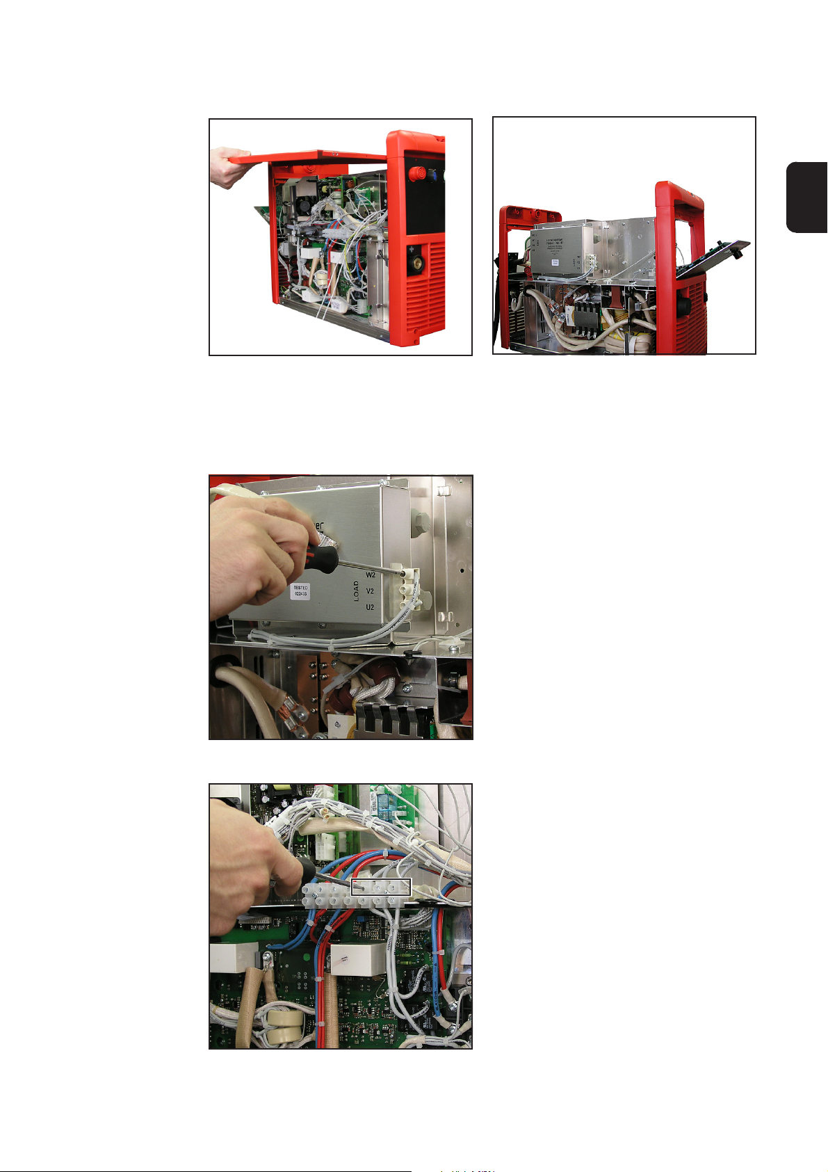
6. Carefully pull the housing apart at the front and rear and remove the handle and
housing cover.
EN
Removing the
cable harness
Removing the handle and housing cover
Opened power source
The existing cable harness on the line filter output is replaced by a new one that has an
additional connection cable. To remove the old cable harness:
1. Undo the 3 block terminals on the lefthand side of the housing (U2, V2, W2)
Undoing block terminals on the left-hand
side of the housing
Undoing block terminals on the right-hand
side of the housing
5
2. Undo the 3 block terminals on the
right-hand side of the housing (5, 6, 7)
Page 23

Removing the
cable harness
(continued)
3. Remove the cable harness from the
housing and replace with the new one.
Detached cable
Removing mounting plate and
RP24-10 PCB/
detaching the
back panel
(2)(1) (3)
Removing connections
(4)
(4)
1. Remove connections:
- External start option (1)
- LocalNet (2)
- LHSB (3)
(4)(4)
2. Loosen the spacers (4) on the back
panel and remove mounting plate and
RP24-10 PCB (external start option).
3. Remove the back panel
Removing the mounting plate and RP24-10
PCB from the back panel
6
Page 24

Fitting the heater installation set
General
Fitting the thermostatic switch
The following sections cover the installation of the thermostatic switch and the transformer. The 150 W heating element is only fitted once the leads in the housing have been
connected and is therefore not covered in the following sections.
1. Open the cable tie on cable harness
for the RP24-10 PCB as far as necessary using cutting pliers
2. Secure the thermostatic switch (1)
with two 3.5 x 9.5 mm self-tapping
fillister head screws (2) under the print
RP24-10 (3).
(2) (1) (2) (3)
Fitting the thermostatic switch
EN
Fitting the transformer
(1)
(1)
Fitting the transformer
1. Fasten the transformer to the transformer fitting panel using four M4 hex
nuts and four 3.2 mm shims
2. Secure the transformer fitting panel
using three M5 x 10 (1) mm Taptite
screws
(1)
7
Page 25

Fitting the plug to
the new back
panel
(1)
(2)
(3)
X9
LHSBOPTION
2,0 AT
(4)
New back panel
(1) Cutout for LocalNet connection
(2) Cutout for connection option (external start installation set)
(3) Cutout for LHSB connection
(4) 2A slow blow fuse for additional heater 6.3 x 32
(5) Main switch for additional heater
Not illustrated on rear:
(6) 200 W heater
1. Fit the LocalNet connection socket to the rear of the new housing
2. Fit the external start option to the rear of the new housing
3. Fit the LHSB connection socket to the rear of the new housing
(5)
8
Page 26

Installing the heater kit in devices with serial numbers prior to 18031198
General
Fitting the thermostatic switch
and securing the
RP24-10 PCB
inside the housing
In devices with serial numbers prior to 18031198, install the heater as described below.
Important! The serial number can be found on the rating plate of the device.
WARNING! Risk of damage by drilling through cables or electrical components
underneath the drilling location. Before drilling, ensure that there are no cables
or electrical components underneath the drilling location. Drill carefully.
1. Open the cable tie on cable harness
for the RP24-10 PC board as far as
necessary using side cutters
2. Place the thermostatic switch onto the
mounting plate of the RP24-10 PC
board (1) and mark drilling points
3. Drill two 3 mm fastening holes (0.12
in.). Drilling template:
24 mm
(.94 in.)
4. Secure the thermostatic switch with
two 3.5 x 9.5 mm self-tapping fillister
head screws.
(2)(1)
Drilling holes for thermostatic switch
5. Drill out a 6 mm hole (0.24 in) at
position (2) (fastening to earthing
spacer)
EN
(3) (4)
(3)(3)
Fitting the mounting plate and RP24-10
PCB
6. Place the mounting plate with PC
board RP24-10 on the spacers (3) and
earthing spacers (4) inside the device
and
7. Fasten the mounting plate using three
M4 x 10 mm spacers
8. Fasten the mounting plate to the
earthing spacer using an M5 nut
9
Page 27

Fitting the transformer
WARNING! Risk of damage by drilling through cables or electrical components
underneath the drilling location. Before drilling, ensure that there are no cables
or electrical components underneath the drilling location. Drill carefully.
(1)
Marking out the transformer
approx. 10 cm
approx. 4.0 in
1. Place the transformer (1) in the housing
2. Mark four drilling points
Drilling template:
64 mm
(2.52 in.)
64 mm
(2.52 in.)
3. Drill four 4 mm holes (0.16 in.)
4. Secure the transformer with four M5 x
10 mm Taptite screws
Drilling through holes for transformer
10
Page 28

Preparing to
install the 150 W
heater
WARNING! Risk of damage by drilling through cables or electrical components
underneath or above the drilling location. Before drilling, ensure that there are no
cables or electrical components underneath or above the drilling location. Drill
carefully.
(1)
(1)
Drilling holes for 150 W heater
1. On the front half of the housing (control
panel), drill out, from the bottom to the
top, the existing holes on the base of
the housing (1) to D = 6 mm (24 in)
EN
Fitting the plug to
the new back
panel
Important! Cables must be connected before the heater is screwed into the housing.
(1)
(2)
(3)
X9
LHSBOPTION
2,0 AT
(5)
(4)
New back panel
(1) Cutout for LocalNet connection
(2) Cutout for connection option (external start installation set)
(3) Cutout for LHSB connection
(4) 2A slow blow fuse for additional heater 6.3 x 32
(5) Main switch for additional heater
Not illustrated on rear:
(6) 200 W heater
1. Fit the LocalNet connection socket to the rear of the new housing
2. Fit the external start option to the rear of the new housing
3. Fit the LHSB connection socket to the rear of the new housing
11
Page 29

Connecting the heaters
Connecting the
heaters
Connect the heaters according to the circuit diagram using a new cable harness
Connecting the cable harness according to the circuit diagram
WARNING! Risk of severe damage from cable fire if the cables touch the
heaters When laying the cables, ensure that cables are not touching the
heaters
Important! Lay all cables correctly in the housing and secure with cable ties
1. Connect the new cable harness on the line filter output to connections W2, V2, U2
using the block terminals
2. Feed the cable harness into the housing and connect to the right-hand side of the
housing:
- U2 to block terminal 5
- V2 to block terminal 6
- W2 to block terminal 7
3. Lay connection cable for 150 W heater
in the housing
4. Connect the 150 W heater and feed
into the housing
Connecting the 150 W heater
12
Page 30

Connecting the
heaters
(continued)
5. Screw on the heater using two M5 x
10 mm Taptite screws driven from
below
EN
Connecting the 150 W heater
6. Connect the cable from the heater
main switch and the fuse according to
the mains voltage to the transformer (1
input 0 V) and (4 - 400 V or 5 - 460 V)
Connect the transformer
7. Connect the thermostatic switch (-F2)
8. Connect the 200 W heater
9. Fasten earth cables, for both the heaters, in housing (1), (2)
NOTE! Risk of damage to electronic components. Clean electronic components
from a certain distance only.
10. Clean machine inside with dry reduced compressed air
(1)
(12)
Connecting the 150 W heater earthing Connecting the 200 W heater earthing
13
Page 31

Closing the housing/carrying out the safety inspection
Closing the
housing
CAUTION! Inadequate PE conductor connections can cause seriousinjury and
damage. The housing screws provide a suitable PE conductor connection for
grounding (earthing) the housing and must NOT be replaced by any other
screws which do not provide a reliable PE conductor connection.
1. Insert the housing cover and handle into the housing
2. Fasten the housing cover to the front and back panel using two M 5 x 16 mm Taptite
screws (1) in each case
3. Secure the control panel using three M 5 x 16 mm Taptite screws
(1)
(1)
(2)
(2)(2)
Carrying out a
safety inspection
Fastening the housing cover
4. Secure the new back panel using four M 5 x 16 mm Taptite screws
5. Secure both side panels using three M 5 x 10 mm Taptite screws on each side
NOTE: To ensure the device functions correctly, carry out a function test before
starting work.
6. Carry out function test:
- check using circuit diagram
- switch on heater. If the temperature is higher than 15°C (59° F), briefly bypass
the thermostatic switch to check that the device is working properly.
A safety inspection must be carried out according to national and local regulations whenever one of the following actions has been performed:
- after any changes have been made
- after any additional parts are installed, or after any conversions
- after repair, care and maintenance
- at least every twelve months
The latest version of the work instruction „Safety inspection of welding systems during
repair and maintenance“ can be found on our website.
Securing the front panel
14
Page 32

SCHALTPLAN / CIRCUIT DIAGRAM
Page 33

Heating for pipe 4,100,551
Heating for pipe 4,100,525
33,0030,0115
41,0007,0216
42,0201,2498
42,0201,2850
43,0006,0225 - 200W
43,0006,0226 - 150W
42,0409,3221
43,0002,0423 (5pol.)
43,0002,0358 (3pol.)
42,0406,0299
41,0007,0169
41,0007,0158
41,0007,0161 - 2A
41,0007,0159
41,0015,0033
41,0006,0095
42,0409,3200
42,0402,0038
Installation kit
Ersatzteilliste / Spare parts list / Listes de pièces de rechange / Lista de repuestos / Lista de pecas sobresselentes / Lista dei Ricambi
el_fr_st_so_01345 012008
1/1
Page 34

FRONIUS INTERNATIONAL GMBH
Froniusplatz 1, A-4600 Wels, Austria
Tel: +43 (0)7242 241-0, Fax: +43 (0)7242 241-3940
E-Mail: sales@fronius.com
www.fronius.com
Under http://www.fronius.com/addresses you will find all addresses
www.fronius.com/addresses
of our Sales & service partners and Locations.
ud_fr_st_so_00082 012011
 Loading...