


/ Battery Charging Systems / Welding Technology / Solar Electronics
DE
EN
Umbau-Set Netzfilter TP 3500
TP 3500 mains filter conversion kit
Umbauanleitung
Stabelektroden-Stromquelle
Conversion instructions
Rod electrode power source
42,0410,1985 002-06082013

0

Allgemeines
(5)(4) (7)(6)
DE
Sicherheit
Lieferumfang
WARNUNG! Ein elektrischer Schlag kann tödlich sein. Ist die Stromquelle wäh-
rend der Arbeiten am Netz angesteckt, besteht die Gefahr schwerwiegender Personen- und Sachschäden. Sämtliche Arbeiten am Gerät nur durchführen, wenn:
- der Netzschalter der Stromquelle in Stellung - O - geschaltet ist
- die Stromquelle vom Netz getrennt ist
WARNUNG! Fehlbedienung kann schwerwiegende Personen- und Sachschäden verursachen. Nachfolgend beschriebene Tätigkeiten dürfen nur von geschultem Fachpersonal durchgeführt werden, wenn folgende Dokumente vollständig
gelesen und verstanden wurden:
- diese Bedienungsanleitung
- sämtliche Bedienungsanleitungen der Systemkomponenten, insbesondere
Sicherheitsvorschriften
(1) Luftleitblech (8) Schutzbeschaltung Plus
(2) Luftführung (9) Schutzbeschaltung Minus
(3) Schraube TX20 (5 Stk.) (10) Kabelbinder klein
(4) Schraube TX25 M5 x 10 (3 Stk.) (11) Kabelbinder groß (2 Stk.)
(5) Schraube TX25 M5 x 8 (4 Stk.) (12) Spreizanker
(6) Box-Netzfilter (13) Halterung Stromsensor
(7) Schutzleiter-Drossel
Benötigtes Werkzeug
Übersicht
- Torx-Schraubendreher TX 20
- Torx-Schraubendreher TX 25
- Seitenschneider
- Schlitz-Schraubendreher klein
(3)(2)(1)
TP 3500 vor Netzfilter-Umbau (Print-Netzfilter) TP 3500 nach Netzfilter-Umbau (Box-Netzfilter)
Beim Umbau werden folgende Veränderungen an der Stromquelle vorgenommen:
- Print-Netzfilter (2) wird durch Box-Netzfilter (5) ersetzt
- Schutzleiter-Drossel (1) wird durch neue Schutzleiter-Drossel (4) ersetzt
- Schutzbeschaltung der (-) Strombuchse wird durch neue Schutzbeschaltung ersetzt
- Halterung Stromsensor (3) wird durch neue Halterung (6) ersetzt
- Die (+) Strombuchse erhält ebenfalls eine Schutzbeschaltung (7)
- Sechskant-Schlüssel SW17
- Kreuzschlitz-Schraubendreher PH1
- Sechskant-Schlüssel SW8
1

Netzfilter tauschen
1
5
7
3
Vorbereitungen
Print-Netzfilter
ausbauen
(2) (3) (4)(1)
4
(1) (2) (3) (4) (5) (6) (7) (8) (9)
Netzschalter der Stromquelle in Stel-
1
lung - O - schalten
Stromquelle vom Netz trennen
2
7 Schrauben TX25 (1) entfernen
3
Rechtes Seitenteil (2) entfernen
4
Linkes Seitenteil entfernen
5
Deckel (3) entfernen
6
Griffstange (4) entfernen
7
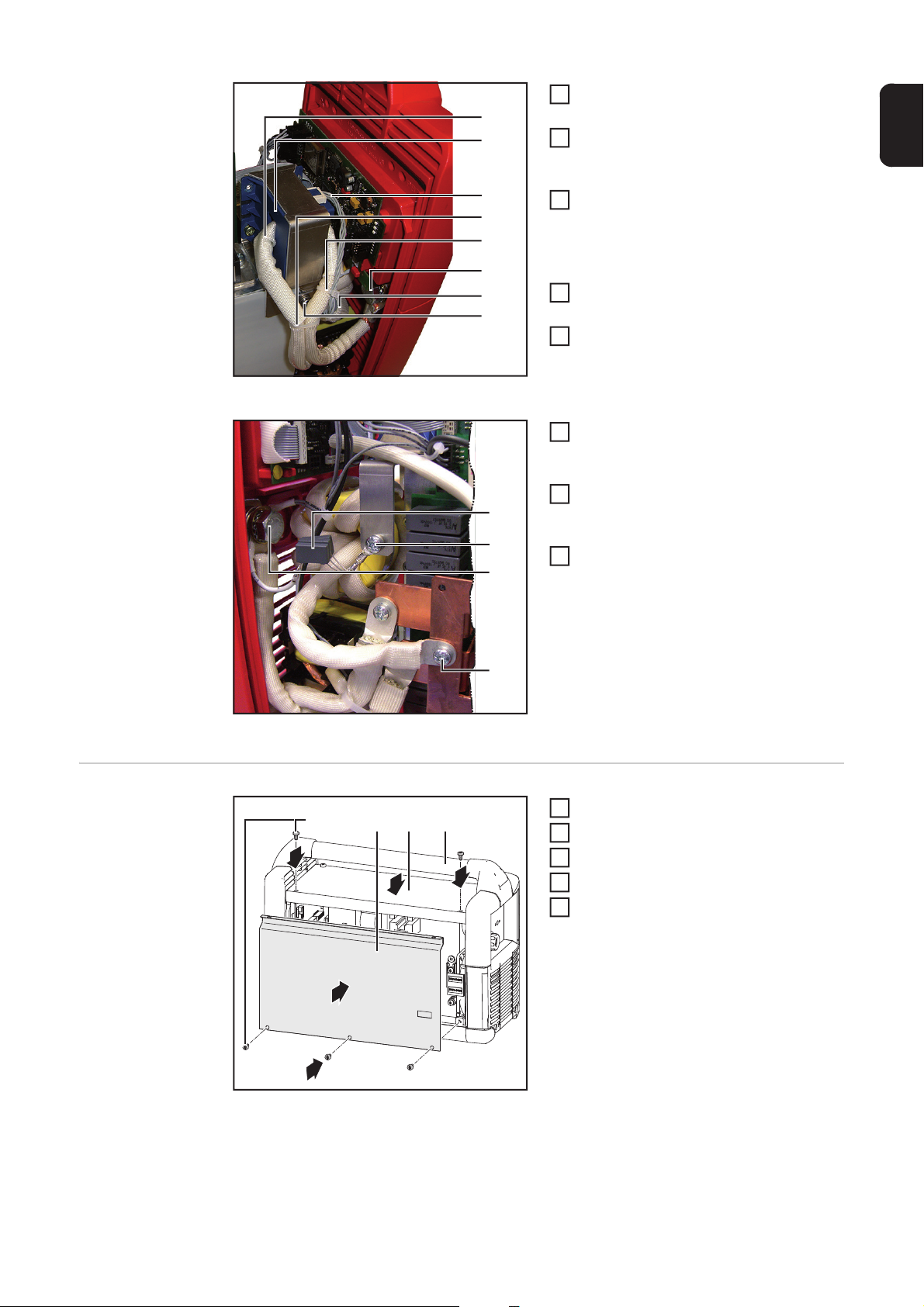
Kabelbinder (4) lösen
Schutzleiter-Drossel (3) abklemmen
2
und entfernen
Erdungsleitungen (2) abklemmen
3
Schrauben (1) + (8) lösen und Print-
4
Netzfilter (9) von Hauptschalter und
Gleichrichter abklemmen
Leitung Hauptschalter-Signal (5) entfernen
– wird nicht mehr benötigt
TP 3500 für den
Einbau des BoxNetzfilters vorbereiten
(1) (2) (4)(3)
(5) (6) (7)
(8)
(9)
(10)
(11)
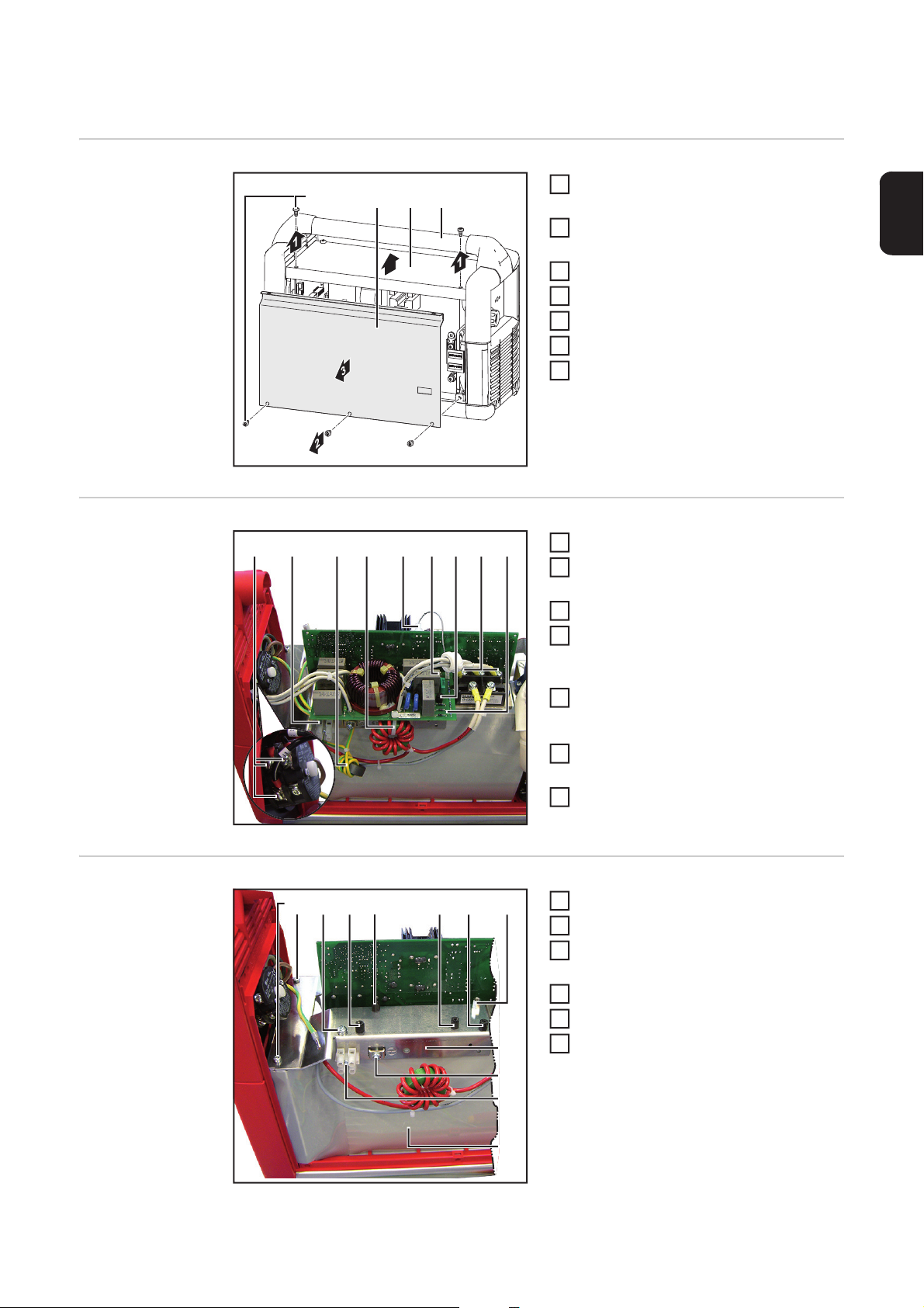
4 Kunststoff-Distanzen (7) und Mes-
6
singdistanz (6) entfernen
Print-Netzfilter (9) entfernen
Klemmen (9) und (10) entfernen
1
3 Schrauben (1) + (2) entfernen
2
4 Kunststoff-Distanzen (3) - (6) und
Messingdistanz (7) entfernen
Luftleitblech (8) entfernen
4
Luftführung (11) entfernen
5
Neue Luftführung (23) einbauen
6
2

(1) (12)(13) (15)(14)
8
(16) (17)
(18)
(19)
(9)
(20)
(10)
(21)
(22)
(23)
Neues Luftleitblech (19) mit Schrauben
7
(1) befestigen
Neues Luftleitblech (19) mit Schrauben
(13) - (18) befestigen
– Schrauben sind im Lieferumfang
Klemmen (9) und (10) auf neuem Luft-
9
leitblech montieren
Spreizanker (20) montieren und Dros-
10
sel (21) daran mit einem Kabelbinder
befestigen
Neue Schutzleiterdrossel (22) an den
11
11
Klemmen (9) und (10) anklemmen
Netzkabel-Schutzleiter (12) an Klem-
12
me (10) anklemmen
DE
Box-Netzfilter einbauen
(2) (3) (4) (5)
(1) (7)(6)
(X2)
(L3) (L2)(L1)
(X4)
(X6)
Box-Netzfilter (5) mit 4 Schrauben (2)
1
befestigen
– Schrauben sind im Lieferumfang
Erdungskabel (3) für Deckel an Klem-
2
me (4) anklemmen
Box-Netzfilter am Hauptschalter an-
3
schließen (L1) - (L3)
Kabel zum Hauptschalter mit kleinem
4
Kabelbinder (1) bündeln
Box-Netzfilter am Gleichrichter an-
5
schließen (X2) - (X6)
Leitung Hauptschalter-Signal (6) am
6
Print LCA35 (7) anstecken und mit
kleinem Kabelbinder bündeln
3

Stromsensor tauschen
(6)
(7)
(8)
(10)
(5)
(9)
1
5
(5)
(4)
(3)
(2)
(1)
Stromsensor ausbauen
(1)
(2)
(3)
(4)
Ansicht von Rechts Ansicht von Links
(-) Strombuchse (1) mit Sechskant-Schlüssel SW17 abklemmen
Schrauben (2) + (4) lösen und Schutzbeschaltung (3) entfernen
2
(+) Strombuchse (6) mit Sechskant-Schlüssel SW17 abklemmen
3
2 Kabelbinder (5) entfernen
4
Stecker Stromsensor (10) abziehen
2 Schrauben (7) der Halterung Stromsensor (9) entfernen
6
Kabel (8) aus dem Stromsensor ausfädeln und Stromsensor dem Gerät entnehmen
7
Stromsensor für
den Einbau vorbereiten
Stromsensor einbauen
(1) (2) (4)(3)
Schrauben (2) + (3) entfernen
1
Stromsensor (4) aus Halterung (1) ent-
2
fernen
Stromsensor (4) in neue Halterung ein-
3
setzen
Mit Schrauben (3) + (4) die neue Halte-
1
rung Stromsensor (2) befestigen
Stecker (5) am Stromsensors anste-
2
cken (1)
4
Ansicht von Links
7
(16)
(14)
(15)
(17)
8
5
(6)
(7)
(8)
(9)
(10)
(11)
(12)
(13)
Kabel (6) der (+) Strombuchse durch
3
Stromsensor (7) fädeln
Schutzbeschaltung Plus (12) und Ka-
4
bel (6) mit Sechskant-Schlüssel SW17
an (+) Strombuchse (11) anklemmen
Schutzbeschaltung Plus (12) mit
5
Schraube (13) an Halterung Stromsensor anklemmen
– Schraube ist im Lieferumfang
Kabel (6) der (+) Strombuchse mit
6
großem Kabelbinder (9) bündeln
Kabel (8) des Stromsensors mit
kleinem Kabelbinder bündeln
Schutzbeschaltung Minus (14) mit
Sechskant-Schlüssel SW17 an
(-) Strombuchse (16) anklemmen
Schutzbeschaltung Minus (14) mit
9
Schraube (15) an Halterung Stromsensor anklemmen
Leitung der Ausgangsdrossel mit
10
Schraube (17) befestigen
DE
Abschließende
Tätigkeiten
Ansicht von Rechts
4
3
Griffstange (4) einsetzen
(2) (3) (4)(1)
1
4
1
Deckel (3) aufsetzen
2
Linkes Seitenteil einsetzen
3
Rechtes Seitenteil (2) einsetzen
4
Deckel und Seitenteile mit 7 Schrauben TX25 (1) befestigen
2
5

6

General
(5)(4) (7)(6)
Safety
Scope of supply
WARNING! An electric shock can be fatal. If the power source is connected to the
mains electricity supply while working on the device, there is a high risk of very
serious injury and damage. Before carrying out any work on the device make sure
that:
- the power source mains switch is in the "O" position
- the power source is unplugged from the mains
WARNING! Operating the equipment incorrectly can cause serious injury and
damage. All activities described below may only be performed by trained and
qualified personnel who have thoroughly read and understood the following documents:
- these operating instructions
- all the operating instructions for the system components, especially the safety rules
(1) Air baffle (8) Protective circuit (+)
(2) Air guide (9) Protective circuit (-)
(3) TX20 screw (5x) (10) Cable tie, small
(4) TX25 screw, M5 x 10 (3x) (11) Cable tie, large (2x)
(5) TX25 screw, M5 x 8 (4x) (12) Expansion bolt
(6) Box mains filter (13) Current sensor holder
(7) Ground conductor choke
EN
Tools required
Overview
- TX20 Torx screwdriver
- TX25 Torx screwdriver
- Cutting pliers
- Slotted screwdriver, small
(3)(2)(1)
TP 3500 before mains filter conversion (PC board
mains filter)
- Allen key, size 17
- Phillips screwdriver, PH1
- Allen key, size 8
TP 3500 after mains filter conversion (box mains filter)
7

The following changes are made to the power source as part of the conversion process:
- PC board mains filter (2) is replaced by the box mains filter (5)
- Ground conductor choke (1) is replaced by a new ground conductor choke (4)
- Protective circuit of the (-) current socket is replaced by a new protective circuit
- Current sensor holder (3) is replaced by a new holder (6)
- The (+) current socket is also fitted with a protective circuit (7)
8
Replacing the mains filter
1
5
7
3
Preparatory work
Removing the PC
board mains filter
(2) (3) (4)(1)
4
(1) (2) (3) (4) (5) (6) (7) (8) (9)
Turn the power source mains switch to
1
the "O" position
Disconnect the power source from the
2
mains
Remove the seven TX25 screws (1)
3
Remove the right side panel (2)
4
Remove the left side panel
5
Remove the lid (3)
6
Remove the handle (4)
7
Remove the cable tie (4)
Disconnect and remove the ground
2
conductor choke (3)
Disconnect the earth cables (2)
3
Undo screws (1) + (8) and disconnect
4
PC board mains filter (9) from the main
switch and rectifier
Remove the main switch signal line (5)
– is no longer required
EN
Preparing the TP
3500 for installation of the box
mains filter
(1) (2) (4)(3)
(5) (6) (7)
(8)
(9)
(10)
(11)
Remove the four plastic spacers (7)
6
and the brass spacer (6)
Remove the PC board mains filter (9)
Remove terminals (9) and (10)
1
Remove three screws (1) + (2)
2
Remove the four plastic spacers (3) (6) and the brass spacer (7)
Remove air baffle (8)
4
Remove air guide (11)
5
Fit new air guide (23)
6
9

(1) (12)(13) (15)(14)
8
(16) (17)
(18)
(19)
(9)
(20)
(10)
(21)
(22)
(23)
Secure new air baffle (19) using
7
screws (1)
Secure new air baffle (19) using
screws (13) - (18)
– screws are in the scope of supply
Fit terminals (9) and (10) to the new air
9
baffle
Fit the expansion bolt (20) and secure
10
the choke (21) to it using a cable tie
Connect the new ground conductor
11
11
choke (22) to terminals (9) and (10)
Connect the mains cable ground con-
12
ductor (12) to terminal (10)
Installing the box
mains filter
(2) (3) (4) (5)
(1) (7)(6)
(X2)
(L3) (L2)(L1)
(X4)
(X6)
Secure the box mains filter (5) with four
1
screws (2)
– screws are in the scope of supply
Connect the earthing cable (3) for the
2
lid to terminal (4)
Connect the box mains filter to the
3
main switch (L1) - (L3)
Bind the cables to the main switch
4
using a small cable tie (1)
Connect the box mains filter to the rec-
5
tifier (X2) - (X6)
Connect the main switch signal line (6)
6
to PC board LCA35 (7) and bind together using a small cable tie
10

Replacing the current sensor
(6)
(7)
(8)
(10)
(5)
(9)
1
5
(5)
(4)
(3)
(2)
(1)
Removing the
current sensor
(1)
(2)
(3)
(4)
View from right View from left
Disconnect the (-) current socket (1) using the size 17 Allen key
Undo screws (2) + (4) and remove protective circuit (3)
2
Disconnect the (+) current socket (6) using the size 17 Allen key
3
Remove the two cable ties (5)
4
Pull off the current sensor plug (10)
Remove two screws (7) from the current sensor holder (9)
6
Thread the cable (8) out of the current sensor and remove the current sensor from the
7
device
EN
Preparing the current sensor for installation
Installing the current sensor
(1) (2) (4)(3)
Remove screws (2) + (3)
1
Take the current sensor (4) out of the
2
holder (1)
Insert the current sensor (4) into the
3
new holder
Secure the new current sensor holder
1
(2) using screws (3) + (4)
Connect the plug (5) to the current sen-
2
sor (1)
11

View from left
7
(16)
(14)
(15)
(17)
8
5
(6)
(7)
(8)
(9)
(10)
(11)
(12)
(13)
Thread the cable (6) of the (+) current
3
socket through the current sensor (7)
Connect the (+) protective circuit (12)
4
and cable (6) to the (+) current socket
(11) using the size 17 Allen key
Connect the (+) protective circuit (12)
5
to the current sensor holder using
screw (13)
– Screw is in the scope of supply
Bind the (+) current socket cable (6)
6
using a large cable tie (9)
Bind the current sensor cable (8) using
a small cable tie
Connect the (-) protective circuit (14) to
the
(-) current socket (16) using the size 17
Allen key
Connect the (-) protective circuit (14) to
9
the current sensor holder using screw
(15)
Secure the output choke line using
10
screw (17)
And finally...
View from right
4
Fit the handle (4)
(2) (3) (4)(1)
1
4
1
Fit the lid (3)
2
Fit the left side panel
3
Fit the right side panel (2)
4
Secure the lid and side panels using
seven TX25 screws (1)
2
3
12

EN
13

FRONIUS INTERNATIONAL GMBH
Froniusplatz 1, A-4600 Wels, Austria
Tel: +43 (0)7242 241-0, Fax: +43 (0)7242 241-3940
Under http://www.fronius.com/addresses you will find all addresses
of our Sales & service partners and Locations
E-Mail: sales@fronius.com
www.fronius.com
www.fronius.com/addresses
 Loading...