

Page 1

Fronius prints on elemental chlorine free paper (ECF) sourced from certified sustainable forests (FSC).
/ Perfect Charging / Perfect Welding / Solar Energy
TIME
焊枪
Bedienungsanleitung
DEENZH
MIG/MAG Hand-Schweißbrenner
Operating Instructions
MIG/MAG manual welding torch
操作说明书
MIG/MAG 手工焊炬
42,0410,0232 005-29052020
Page 2

2
Page 3

Sehr geehrter Leser
Einleitung Wir danken Ihnen für Ihr entgegengebrachtes Vertrauen und gratulieren Ihnen zu Ihrem
technisch hochwertigen Fronius Produkt. Die vorliegende Anleitung hilft Ihnen, sich mit
diesem vertraut zu machen. Indem Sie die Anleitung sorgfältig lesen, lernen Sie die vielfältigen Möglichkeiten Ihres Fronius Produktes kennen. Nur so können Sie seine Vorteile
bestmöglich nutzen.
Bitte beachten Sie auch die Sicherheitsvorschriften und sorgen Sie so für mehr Sicherheit
am Einsatzort des Produktes. Sorgfältiger Umgang mit Ihrem Produkt unterstützt dessen
langlebige Qualität und Zuverlässigkeit. Das sind wesentliche Voraussetzungen für hervorragende Ergebnisse.
DE
3
Page 4

4
Page 5

Inhaltsverzeichnis
Sicherheit ................................................................................................................................................... 7
Bestimmungsgemäße Verwendung...................................................................................................... 7
Sicherheit.............................................................................................................................................. 7
Allgemeines ............................................................................................................................................... 9
Gerätekonzept ...................................................................................................................................... 9
Technische Daten................................................................................................................................. 9
Beschreibung der Brennerteile ............................................................................................................. 9
Vor der Inbetriebnahme ............................................................................................................................. 11
Vorbereiten des Schweißbrenners........................................................................................................ 11
Wechsel der Stahldraht-Führungseele ................................................................................................. 11
Kühlgerät............................................................................................................................................... 11
Pflege und Wartung .............................................................................................................................. 12
DE
5
Page 6

6
Page 7

Sicherheit
DE
Bestimmungsgemäße Verwendung
Sicherheit
Der MIG/MAG Hand-Schweißbrenner ist ausschließlich zum MIG/MAG-Schweißen bei
manuellen Anwendungen bestimmt.
Eine andere oder darüber hinausgehende Benutzung gilt als nicht bestimmungsgemäß.
Für hieraus entstehende Schäden haftet der Hersteller nicht.
Zur bestimmungsgemäßen Verwendung gehört auch
- das Beachten aller Hinweise aus der Bedienungsanleitung
- die Einhaltung der Inspektions- und Wartungsarbeiten
WARNUNG!
Gefahr durch Fehlbedienung und fehlerhaft durchgeführte Arbeiten.
Schwerwiegende Personen- und Sachschäden können die Folge sein.
► Alle in diesem Dokument beschriebenen Arbeiten und Funktionen dürfen nur von ge-
schultem Fachpersonal ausgeführt werden.
► Dieses Dokument lesen und verstehen.
► Sämtliche Bedienungsanleitungen der Systemkomponenten, insbesondere Sicher-
heitsvorschriften lesen und verstehen.
WARNUNG!
Gefahr durch elektrischen Strom und Verletzungsgefahr durch austretende Drahtelektrode.
Schwerwiegende Personen- und Sachschäden können die Folge sein.
► Netzschalter der Stromquelle in Stellung - O - schalten.
► Stromquelle vom Netz trennen.
► Sicherstellen, dass die Stromquelle bis zum Abschluss aller Arbeiten vom Netz ge-
trennt bleibt.
WARNUNG!
Gefahr durch elektrischen Strom.
Schwerwiegende Personen- und Sachschäden können die Folge sein.
► Sämtliche Kabel, Leitungen und Schlauchpakete müssen immer fest angeschlossen,
unbeschädigt, korrekt isoliert und ausreichend dimensioniert sein.
VORSICHT!
Verbrennungsgefahr durch heiße Schweißbrenner-Komponenten und heißes Kühlmittel.
Schwere Verbrühungen können die Folge sein.
► Vor Beginn aller in dieser Bedienungsanleitung beschriebenen Arbeiten sämtliche
Schweißbrenner-Komponenten und das Kühlmittel auf Zimmertemperatur (+25 °C,
+77 °F) abkühlen lassen.
7
Page 8

VORSICHT!
Beschädigungsgefahr durch Betrieb ohne Kühlmittel.
Schwerwiegende Sachschäden können die Folge sein.
► Wassergekühlte Schweißbrenner nie ohne Kühlmittel in Betrieb nehmen.
► Für hieraus entstandene Schäden haftet der Hersteller nicht, sämtliche Gewährleis-
tungsansprüche erlöschen.
VORSICHT!
Gefahr durch Kühlmittelaustritt.
Schwerwiegende Personen- und Sachschäden können die Folge sein.
► Die Kühlmittel-Schläuche der wassergekühlten Schweißbrenner immer mit dem darauf
montierten Kunststoff-Verschluss verschließen, wenn diese vom Kühlgerät oder vom
Drahtvorschub getrennt werden.
8
Page 9

Allgemeines
RICHTIGRICHTIG FAL SCHFALSCH
Bohrung des
Kontaktrohres
I
2
I
1
I
nur Punktkontakte
Förderrolle
Gerätekonzept Es stellte für die Fronius-Entwicklungsabteilung eine große Herausforderung dar, einen
MAG-Brenner mit einer Leistung von 760 A bei 100 % Einschaltdauer zu entwickeln, der
nicht schwerer und nicht unflexibler als herkömmliche, wassergekühlte MIG/ MAG-Brenner sein sollte.
Mit dem vorliegenden Produkt ist es gelungen einen einfachen, betriebsicheren Aufbau,
mit einem guten Handling, einem geringen Gewicht und ausgezeichneten Kühlleistungen,
bei einer ungewöhnlichen Flexibilität des Schlauchpaketes zu erreichen.
Die Gasströmung und die Drahtfördereigenschaften wurden in ausgedehnten Versuchsreihen optimiert und von anerkannten Experten als äußerst positiv eingestuft
DE
Technische Daten
Beschreibung der
Brennerteile
Leistung bis Gas ED Draht Ø
760 A T.I.M.E. 100 % 0,8 - 1,2 mm
Zu groß gewählte oder ausgeschliffene
Kontaktrohre beeinflussen das Schweißergebnis negativ.
Abb.1
Der Brennerkörper in Schwanenhalsform hat gegenüber der geraden Pistolenform den
Vorteil der sicheren Stromübertragung, weil die Drahtelektrode durch die Umlenkung im
Rohrbogen eine Zwangskontaktierung im Kontaktrohr erhält: (Abb.1) Um einen optimalen
Stromübergang auf die Drahtelektrode zu gewährleisten muß das Kontaktrohr mit seiner
Bohrung auf den jeweiligen Drahtdurchmesser abgestimmt sein. (Prägung laut Tabelle beachten!). Das Kontaktrohr weist eine elliptische Form auf und ist zur Veränderung der Länge des freien Drahtendes damit hervorragend geeignet.
Prägung Draht Ø
0,030 oder 0,035 0,8
0,039 oder 0,045 1,0
0,052 1,2
Die Isolierhülse (muß immer montiert sein) isoliert bei Spritzeranhäufungen den Gasdüseninnenraum zum Düsenstock hin ab.
Der Düsenstock dient zur gleichmäßigen Gasverteilung und zur Aufnahme des Kontaktrohres.
Die Gasdüse (konisch und zylindrisch) ist direkt wassergekühlt und mit einer externen
Kühlwasserzufuhr versehen. Die Befestigung erfolgt durch die Überwurfmutter und den
Isloieranschlagring.
9
Page 10
Die ausgezeichnete Kühlung der Gasdüse verhindert das Anhaften von Schweißspritzern
und das Verwenden von Schweißsprays kann völlig entfallen.
Die externen Kühlwasserzuführungen sind mit Schnellverschlüssen ausgestattet, die
ein leichtes Abnehmen der Gasdüse ermöglichen. Der vordere Teil ist mit metallgeflechtumhüllten Schläuchen zur Verschleißminderung ausgestattet.
Der in zwei Halbschalen ausgeführte Handgriff aus hochwertigem Kunststoff ist teilbar.
Mit der eingebauten Brennertaste werden vom Schweißer die gewünschten Steuerfunktionen Parameter 1 und 2 abgerufen. Die elektrische Verbindung zum T.I.M.E.-51- Drahtvorschubgerät wird über die Steuerleitung hergestellt und über den Brenner-
Steuerstecker am Vorschubgerät eingesteckt. Beim Maschinenbrenner wird der Handgriff
durch das Aufnahmerohr 20 Ø 44 x 190 mm ersetzt und die Steuerleitung entfällt.
Mit dem bewährten Fronius-Zentralanschluß kann der Brenner rasch und problemlos
von Hand ohne Werkzeug am Drahtvorschubgerät montiert werden.
Der Gasanschluß ist extern ausgeführt und mit einer Schnellkupplung versehen um das
Eindringen von Kühlwasser mit Sicherheit zu vermeiden.
Beim Anschließen des vorher richtig ausgerüsteten Brenners wird dieser mit dem Einlaufrohr voran in den Zentralanschluß des Vorschubgerätes eingeführt und mittels Überwurf-
mutter gut festgezogen. Die Überwurfmutter muß sich leicht aufschrauben lassen.
Ansonst Gewinde und O-Ring von Schmutz säubern und auf mechanische Beschädigung prüfen.
Die Schlauchmuffe verhindert ein zu starkes Abknicken des Brennerschlauchpaketes.
Der Aufkleber auf der Schlauchmuffe gibt Aufschluß über die Brennerlänge.
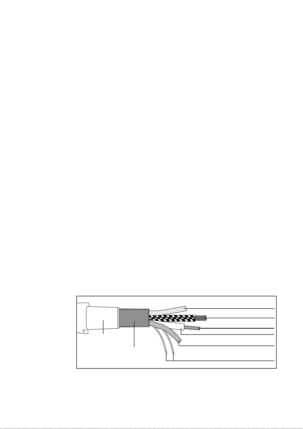
Das Schlauchpaket stellt das Verbindungselement zwischen dem Drahtvorschubgerät und
dem Schweißbrenner dar. Es besteht aus dem Schutzschlauch, dem Gasschlauch, dem
Drahtförderschlauch, der Drahtführungsseele, dem Wasservorlaufschlauch,´dem StromWasserkabel und der Steuerleitung (Abb. 2).
Da die zu verschweißenden Drahtdurchmesser auf max. 1,2 mm begrenzt sind könnte für
den Drahtförderschlauch ein wesentlich dünneres und flexibleres Material verwendet werden. Damit wurde die Handhabbarkeit des Brenners, insbesondere das Verdrehen des
Handgriffes und die Biegekraft wesentlich vermindert. Die Drahtdüse ist aus Stahl gefertigt und ermöglicht ein äußerst kurzes, ungeführtes Drahtstück.
Die Drahtführungsseele besteht aus einer Stahlspirale mit einem Außendurchmesser von
4,0 mm und einem Innendurchmesser von ca. 1,6 mm. Damit können alle Drahtdurchmesser von 0,8 - 1,2 mm problemlos gefördert werden.
Gasschlauch
Wasser-, Stromkabel
Drahtführungsseele
Knickschutz
Schutzschlauch
Drahtförderschlauch
Wasserschlauch
10
Steuerleitung
Abb.2
Page 11
Vor der Inbetriebnahme
1
4
7
10
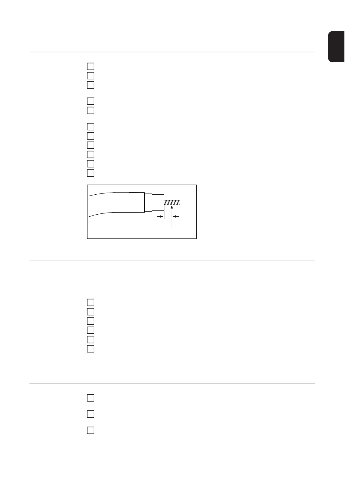
5 mm
Drahtführungseele hier abzwicken
3
6
3
DE
Vorbereiten des
Schweißbrenners
Schlauchpaket gerade auslegen
Gasdüse und Düsenstock vom Brennerkörper abnehmen.
2
Stahlseele von rückwärts durch den Zentralanschluß in das Schlauchpaket einschie-
3
ben.
Drahtdüse in das Einlaufrohr einschrauben.
Seele am Pistolenkörperende mit einer Zugabe von 5 mm abzwicken (Abb. 3). Innen-
5
durchmesser nicht verkleinern!
Seelenende entgraten (Außen- und Innenkante brechen).
6
Düsenstock einschrauben und festziehen (Maulschlüssel).
Schlauchpaket am Gerät montieren.
8
Schweißdraht in das Schlauchpaket einschleichen.
9
Kontaktrohr mit Spezialzange einstecken und fixieren.
Gasdüse mit Isolierhülse aufsetzen und Kühlschläuche verbinden
11
Abb.3
Wechsel der
Stahldraht-Führungseele
Kühlgerät Vor Inbetriebnahme des Gerätes Wasserstand und Wasserqualität kontrollieren
Durch Verschleiß, Metallabrieb und Drahtverunreinigungen wird die Drahtförderung mehr
und mehr erschwert. Die Seele muß deshalb von Zeit zu Zeit gewechselt werden. Dieser
Wechsel wird wie folgt durchgeführt:
Draht abspulen.
1
Brenner abnehmen und geradlinig auslegen.
2
Gasdüse, Kontaktrohr und Düsenstock vom Brennerkörper abnehmen.
Drahtdüse abschrauben.
4
Drahtführungsseele nach rückwärts herausziehen.
5
Neue Drahtführungsseele mit aufgepreßtem Cu-Klemmring von rückwärts einschieben.
Weitere Vorgangsweise wie bei “Vorbereiten des Schweißbrenners” ab Punkt 3.
1
(eventuell wechseln oder nachfüllen).
Nur sauberes Leitungswasser einfüllen! (Bei Minustemperatur entsprechend dem
2
Aufkleber des Kühlgerätes Spiritus zugeben).
Sollte der Brenner ohne Wasser in Betrieb genommen werden, hat dies einen Defekt
von Brennerkörper oder Schlauchpaket zur Folge (kein Garantieanspruch)
11
Page 12

Pflege und War-
3
6
tung
WICHTIG! Vor Wartungs- und Montagearbeiten am Brenner: Schweißgerät abschalten!
Um einen störungsfreien Betrieb zu gewährleisten, sind nachstehende Punkte zu beachten:
Nach jedem Wechsel der Drahtspule ist der einwandfreie Einlauf in die Drahtdüse zu
1
kontrollieren. Bei ausgeschliffener Drahtdüse, diese erneuern und Drahteinlauf neu
einstellen.
Kontaktrohr abschrauben und das ausgelegte Schlauchpaket mit trockener Pressluft
2
von vorne durchblasen.
Schweißperlen im Inneren der Gasdüse mit Düsenreiniger entfernen.
Kontaktrohr kontrollieren. Durch ständigen Drahtdurchlauf wird die Bohrung größer
4
und es entsteht durch schlechten Stromübergang ein unruhiger Lichtbogen.
Zentralanschluss nachziehen.
5
Regelmäßig Wasserstand und Wasserqualität kontrollieren (nötigenfalls nachfüllen
oder wechseln!)
Wasser-Rückflussmenge im Kühlmittelbehälter überwachen. Wird der Brenner ohne
7
Kühlwasser in Betrieb genommen, hat dies meist einen Defekt von Brennerkörper
oder Schlauchpaket zur Folge (kein Garantieanspruch!)
Hinweise über das Mischverhältnis mit Spiritus bei Minusgraden erhalten Sie aus der
8
jeweiligen Geräte-Bedienungsanleitung.
12
Page 13

Dear reader,
Introduction Thank you for the trust you have placed in our company and congratulations on buying this
high-quality Fronius product. These instructions will help you familiarise yourself with the
product. Reading the instructions carefully will enable you to learn about the many different
features it has to offer. This will allow you to make full use of its advantages.
Please also note the safety rules to ensure greater safety when using the product. Careful
handling of the product will repay you with years of safe and reliable operation. These are
essential prerequisites for excellent results.
EN
13
Page 14

14
Page 15

Contents
Safety......................................................................................................................................................... 17
Bestimmungsgemäße Verwendung...................................................................................................... 17
Safety.................................................................................................................................................... 17
General ...................................................................................................................................................... 19
Device concept ..................................................................................................................................... 19
Technical data....................................................................................................................................... 19
Parts of torch - description................................................................................................................... 19
Before commissioning................................................................................................................................ 21
Preparing the welding torch .................................................................................................................. 21
Replacing the steel wire-feed liner........................................................................................................ 21
Cooling unit........................................................................................................................................... 21
Care and maintenance.......................................................................................................................... 22
EN
15
Page 16

16
Page 17

Safety
Proper use The MIG/MAG manual welding torch is intended solely for MIG/MAG welding in manual ap-
plications.
Any use above and beyond this purpose is deemed improper. The manufacturer shall not
be held liable for any damage arising from such usage.
Proper use includes:
- Carefully reading and following all the instructions given in the operating instructions
- Performing all stipulated inspection and maintenance work.
EN
Safety
WARNING!
Danger due to incorrect operation and incorrectly performed work.
This can result in serious injury and damage to property.
► All the work and functions described in this document must only be carried out by
trained and qualified personnel.
► Read and understand this document.
► Read and understand all the Operating Instructions for the system components, espe-
cially the safety rules.
WARNING!
Danger from electric current and risk of injury from the emerging wire electrode.
This can result in serious injury and damage to property.
► Turn the power source mains switch to the "O" position.
► Disconnect the power source from the mains.
► Ensure that the power source remains disconnected from the mains until all work has
been completed.
WARNING!
Danger from electric current.
This can result in serious injury and damage to property.
► All cables, lines and hosepacks must be properly connected, undamaged, correctly in-
sulated and adequately dimensioned at all times.
CAUTION!
Risk of burns from hot welding torch components and hot coolant.
This can result in severe scalds.
► Before commencing any of the work described in these Operating Instructions, allow
all welding torch components and the coolant to cool to room temperature (+25 °C, +77
°F).
17
Page 18

CAUTION!
Risk of damage due to operation without coolant.
This can result in serious damage to property.
► Never operate a water-cooled welding torch without coolant.
► Fronius shall not be liable for any damage resulting from such action. In addition, no
warranty claims will be entertained.
CAUTION!
Danger from coolant leakage.
This can result in serious injury and damage to property.
► Seal the coolant hoses on water-cooled welding torches with the plastic stoppers fitted
to them if the hoses are detached from the cooling unit or the wirefeeder.
18
Page 19

General
CORRECTCORRECT WRONGWRONG
Bore of the
contact tube
I
2
I
1
I
only pointcontact
Wire feed rolls
Device concept The Fronius product development department was presented with a major challenge when
it came to designing a MAG torch with an output of 760 A at 100 % duty cycle that was no
heavier and no less flexible than conventional water-cooled MIG/MAG torches.
The resulting product successfully combines a straightforward and reliable design with
good handling characteristics, low weight and excellent cooling performance, at the same
time as an unusual degree of hose-pack flexibility.
The gas-flow and wirefeed characteristics have been optimized in the course of exhaustive
testing, and have earned highly positive assessments from numerous noted authorities in
the field.
EN
Technical data
Parts of torch -
description
Capacity Gas Duty cycle Wire Ø
760 A T.I.M.E. 100 % 0,8 - 1,2 mm
Contact tubes which are too large, or which
have been ground out by wear, have a very
adverse effect on the welding results.
Fig.1
The advantage of the "swan-neck" shape of the torch body as against a straight "pistol"
shape is that it ensures that current is transferred to the wire electrode, as the bend in the
neck of the torch forces the welding wire to come in contact with the contact tube (Fig. 1).
In order to ensure optimum current transfer to the wire electrode, the bore of the contact
tube must be suitable for the diameter of the wire being used (observe stamped-on labelling). The elliptical shape of the contact tip is ideal for altering the length of the free end of
the wire.
Stamped-on marking Wire Ø
0,030 or 0,035 0,8
0,039 or 0,045 1,0
0,052 1,2
If there are accumulations of spatter, the insulating sleeve (must always be mounted) in-
sulates the inside of the gas nozzle from the tip holder.
The nozzle stock serves to distribute the gas evenly.
Gas nozzles (conical and cylindrical) are directly water cooled and are provided with an
external supply of cooling water. The nozzle is fixed on with the swivel nut and the insu-
lating stop ring.
19
Page 20

The excellent cooling of the gas nozzle prevents welding spatter clinging to it; this is so effective that there is no need to use welding sprays.
The external cooling water supply lines are fitted with quick-action sealing devices
which make it easy to detach the gas nozzle. The tubing in the forward section is sheathed
in flexible braided metal to guard against wear and tear.
The handle is made of high-grade plastic and is designed to be separable (i.e. consists of
two half-shells). The welder can call in the desired control functions (parameters 1 and 2)
from the built-in torch trigger. The torch is electrically connected to the T.I.M.E.-51 wirefeed unit via the control lead which is plugged into the wirefeed unit via the torch control
plug. On the machine torch, the handle is replaced by the holding tube (diam. 20, 44 x 190
mm), and there is no control lead.
The tried-and-tested Fronius central torch connection makes it possible for the torch to
be connected up to the appropriate wire feed device by hand - quickly and easily, and with
no need for any tools.
There is an external gas connection, fitted with a quick-action coupling so as to provide
reliable protection against penetration by cooling water.
To connect up the torch (N.B. this must have been correctly assembled and equipped first),
insert this into the central connector on the wirefeed unit, with the infeed tube first, and fasten it tightly with the swivel nut. It must be possible to screw on the swivel nut easily. If it
is not, clean any dirt off the thread and the O-ring seal and check for mechanical damage.
The anti-kink hose sleeve prevents the torch hose-pack from being bent down too severely. The sticker on the hose sleeve gives details of the length of the torch.
The hose pack is the link between the wirefeed unit and the torch. It consists of the protective hose, the gas hose, the wirefeed hose, the inner liner, the water-flow hose, the current/
water cable and the control lead (Fig. 2).
As there is an upper limit of 1.2 mm on the diameter of the wires to be welded, it has been
possible to use a considerably thinner and more flexible material for the wirefeed hose. By
decreasing the flexural resistance, this has made the torch much “handier” to use - e.g. by
making the handle easier to turn.
The wire inlet nozzle is made of steel and makes it possible for there to be an extremely
short unguided section of wire.
The inner liner consists of a steel spiral with an outside diameter of 4.0 mm and an inside
diameter of approx. 1.6 mm. It enables all diameters of wire to be fed smoothly, from 0.8
mm to 1.2 mm.
Gashose
Water-, current hose
Wire-feeder innerliner
Kink protection
Protective hose
Wire-feeder hose
Water hose
Control line
20
Fig.2
Page 21

Before commissioning
1
4
7
10
5 mm
Clip off inner liner here
3
6
3
Preparing the
welding torch
Lay out the hose pack in a straight line.
Detach the gas nozzle, the nozzle stock and the spatter guard from the torch.
2
Insert the steel inner liner through the central connection (from the rear) and into the
3
hose pack.
Screw the wire nozzle into the infeed tube.
Clip off the inner liner at the end of the torch body (+ 5mm) (Fig. 3). Do not make the
5
inside diameter any smaller!
Debur the end of the liner (i.e. chamfer off the inner and outer edges).
6
Screw in the tip holder and tighten it (open-jawed spanner).
Connect up the hose packet to the machine.
8
Inch the welding wire into the hose pack.
9
Using the special pliers, insert the contact tip and fix it in place.
Attach gas nozzle and insulating sleeve, and connect cooling hoses.
11
EN
Fig.3
Replacing the
steel wire-feed
liner
Cooling unit Before starting to use the machine, check the level and the quality of the cooling water
In the course of time, wear, metal abrasion and soiling from unclean wires make it increasingly difficult for wires to be fed smoothly. For this reason, the inner liner must be changed
from time to time. This is done as follows:
Unreel the wire.
1
Remove the torch and lay it out in a straight line.
2
Detach the gas nozzle, contact tube and nozzle stock from the main body of the torch.
Unscrew the wire nozzle.
4
Pull out the wire-feed inner liner to the rear.
5
Insert, from the rear, a new liner with a pressed-on copper clamping ring.
Now proceed as outlined in the section "Preparing the welding torch", from Point 3 onwards.
1
(top up or change if nec.).
Only use clean tap water! (Where sub-zero ambient temperatures are likely, add alco-
2
hol as per instructions on cooling unit).
If the torch is started up and there is no cooling water, the result is generally a defect
in the torch body or in the hose pack (i.e. no warranty claims will be accepted!)
21
Page 22

Care and mainte-
3
6
nance
IMPORTANT! Before doing any maintenance or service work on the torch: Switch off the
welding machine!
In order to ensure smooth operation, observe the following points:
Every time the wire spool is changed, make sure that the wire runs into the wire inlet
1
nozzle smoothly. If the inlet nozzle is worn out, replace it with a new one and readjust
the wire infeed.
Unscrew the contact tube and blow through the hose pack (lay it out straight first) with
2
dry compressed air, from front to back.
Remove all weld nuggets inside the gas nozzle, using nozzle cleaner.
Check the contact tube. Due to the constant passage of wire, the bore tends to in-
4
crease in size with time, and the poor current transfer which results causes an unsteady arc.
Tighten the central connection.
5
Check the level and the quality of the cooling water at regular intervals (top up or
change if necessary).
Keep an eye on the water return-flow in the coolant reservoir. If there is no cooling wa-
7
ter and the torch is used, this normally results in serious damage to the torch body or
the hose pack (i.e. no claims possible under warranty!)
For details on the alcohol admixture ratio necessary to protect the machine against
8
sub-zero ambient temperatures, see the instruction manual for the machine in question.
22
Page 23

尊敬的读者:
引言 感谢您对我公司的信任并祝贺您使用高科技的 Fronius 产品。您正在阅读的这本使用说明
可以帮助您熟悉该产品。通过仔细阅读该说明,您将了解到 Fronius 产品的多种用途。只
有这样您才能充分发挥它的优点。
同时也请遵守产品安全规程,以确保使用场所中的安全。谨慎使用产品有助于提高其使用
寿命与可靠性。这是取得良好效果的基本前提。
ZH
23
Page 24

24
Page 25

目录
安全 ......................................................................................
预期用途................................................................................
安全标识................................................................................
概述 ......................................................................................
设备设计方案............................................................................
技术数据................................................................................
焊枪零件描述............................................................................
调试之前 ..................................................................................
准备焊枪................................................................................
更换钢导丝管............................................................................
冷却单元................................................................................
保养与维护..............................................................................
27
27
27
29
29
29
29
31
31
31
31
31
ZH
25
Page 26

26
Page 27

安全
预期用途 MIG/MAG 手工焊枪仅适用于手工 MIG/MAG 焊接应用。
任何其他用途均视为“违反指定用途行为”。对于因此类不当使用所导致的任何损失,
制造商概不负责。
预期用途亦指:
- 遵守操作说明书中的所有操作说明
- 执行所有指定的检查和保养作业
ZH
安全标识
警告!
误操作及工作不当时存在危险。
此时可能导致严重的人身伤害和财产损失。
► 仅接受过培训且有资质人员方可执行本文档中所述的全部操作和功能。
► 阅读并理解本文档。
► 阅读并理解有关系统组件的所有操作说明书,尤其是安全规程。
警告!
焊接电流存在危险且裸露的电极丝可能会带来人身伤害风险。
此时可能导致严重的人身伤害和财产损失。
► 将电源主开关切换至“O”位置。
► 断开电源与主电源的连接。
► 在完成所有工作前,请确保电源与主电源之间的连接始终保持断开状态。
警告!
焊接电流存在危险。
此时可能导致严重的人身伤害和财产损失。
► 所有电缆、线路和中继线无论何时都应可靠连接、完好无损、妥善绝缘且尺寸适当。
小心!
高温焊枪部件及高温冷却剂可能会带来灼伤风险。
此时可能导致严重烫伤。
► 在开始这些操作说明书中所述的任何工作前,请将所有焊枪部件及冷却剂冷却至室温
(+25 °C,+77 °F)。
小心!
无冷却剂操作时存在损坏风险。
此时可能导致严重的财产损失。
► 切勿在无冷却剂情况下操作水冷式焊枪。
► 对于由此类行为所导致的任何损失,伏能士概不负责。此外,也不会受理任何保修索
赔。
27
Page 28

小心!
冷却剂泄漏时存在危险。
此时可能导致严重的人身伤害和财产损失。
► 将水冷式焊枪上的冷却剂软管从冷却器或送丝机中分离后,请使用软管上的塑料塞对
软管端进行密封。
28
Page 29

概述
CORRECTCORRECT WRONGWRONG
Bore of the
contact tube
I
2
I
1
I
only pointcontact
Wire feed rolls
设备设计方案 Fronius产品开发部在设计MAG焊枪时候,遇到了巨大的挑战:因为要达到760A输出电流
100%暂载率,但是并没有比传统水冷MIG/MAG焊枪增加重量或者减少灵活性。
Fronius成功地把简单可靠的设计与良好操作性,轻便性及出色的冷却性结合在一起,同
时使得枪护套更柔韧。
气流量和送丝特性在能耗测试过程中得到优化,得到业界很多专家的高度评价。
ZH
技术数据
电流 保护气 暂载率 焊丝
760 A T.I.M.E. 100 % 0,8 - 1,2 mm
触头过大或磨损 。此时可能会对焊接效果
产生负面影响。
图
1
焊枪零件描述 枪头的鹅颈形状的优点是和枪线形设计刚好相反。使焊丝一直与导电嘴保持接触(图1)
, 可确保电流直接过度到焊丝电极上。为了确保合适的电流过度到焊丝电极上,导电嘴必
须与所用焊丝(可观察焊丝标签)相匹配。导电嘴省略的形状是为了变更焊丝末端的度。
如果飞溅累积过多的话,绝热圈(必须一直安装)使里面的喷嘴与末端隔 热。
标签 焊丝直径 Ø
0,030 或 0,035
0,039 或 0,045
0,8
1,0
0,052 1,2
如果飞溅累积过多的话,绝热圈(必须一直安装)使里面的喷嘴与末端隔 热。
导电嘴座可以均匀的分配保护气。
喷嘴(圆锥形,圆柱形)直接水冷却,由外部供应的冷却水直接冷却.喷嘴固。 定在螺母
和绝缘圈上
外部冷却水管可直接与快插连接,这样与喷嘴容易分离.向前的管道被柔 韧金属辫子保护
着, 防止磨损和撕裂。
29
Page 30

手柄由高等级塑料制造,而且设计成可分离式(也就是由两个半边外壳组成)。焊工可以
Protective hose
Kink protection
Control line
Wire-feeder innerliner
Wire-feeder hose
Gashose
Water-, current hose
Water hose
通过安装在内部的焊枪开关得到所想要的控制功能(.参数1和2)。焊枪与TIME-51送丝
系统由控制线通过电缆连接。控制线经由焊枪控制插头插入送丝机系统。机用枪中,手柄
被把持管(直径20.44*190mm)取代,而且没有控制线。
测试过的Fronius焊枪连接头,使焊枪能够与适当的送丝系统接口相连接,。
此连接可快速,很容易而且并不需要任何工具的手工完成。
为了把枪连上(注意:正确装配和预备),首先把接头插入到送丝系统上, 拧紧螺母。它
肯定会很容易拧到螺母上。如果不是,从螺纹和Q型密封圈上清理掉脏东西,还要检查机
械损伤.
反扭结中继线护套防止枪电缆被严重弯曲.护套上的标签标明了焊枪长度的详细资料.
枪电缆是送丝系统和焊枪的链条.它是由防护套,气管,送丝管护套,导丝管, 水管,水
电缆和控制线组成(图2).
比如要焊接直径超过1.2mm焊丝,导丝管护套可能要用到相当薄和更柔韧材料. 通过减少
挠曲阻力,使得焊枪使用更方便 ,比如让焊枪手柄更易翻转. 钢做的导丝嘴,使得可能出
现极其短而且不易控制的焊丝段.
导丝管由外径为4.mm,内径为大约1.6mm的螺旋型的钢组成.它使得从0.8mm到1.2mm的
焊丝都能很顺畅的导入.
30
图
2
Page 31

调试之前
2
5
8
5 mm
Clip off inner liner here
1
4
3
准备焊枪 把焊枪护套直线形摆放,
1
从枪上拆开喷嘴,导电嘴座,分流器
从中间连接头(从后面)把钢导丝管插入护套
3
旋上导丝嘴
4
剪掉枪头处的导丝管(+5mm处)(图3),不要把导丝管留太短
去掉导丝管的毛刺(也就是斜切导丝管和外部边缘)
6
拧紧夹头(用开口扳手)
7
把焊枪连到焊机上
慢慢把焊丝装到焊枪电缆内
9
使用特殊钳子,装上导电嘴,并固定住
10
装上喷嘴夹和喷嘴,接上冷却水管
11
图
3
ZH
更换钢导丝管 在使用过程中,磨损,金属损耗,不干净的焊丝腐蚀,渐渐的使焊丝很难 顺畅的装入导丝
管内. 因为这些原因,导丝管需要不时的更换. 按如下操作:
退回焊丝
移下焊枪,并把焊枪拉直摆放
2
从枪头上拆下喷嘴,导电嘴和导电嘴座
3
送开导丝嘴
从后面拉出导丝管
5
从后面装入一根新导丝管,铜夹头压紧,
6
现在按前段章节”准备焊枪”的概要第3点进行操作.
冷却单元 开始使用机器之前,检查水位和冷却水质量(超过UP水位或者有需要就改变)
保养与维护 重要!在给焊枪做任何维护和服务前,请切断焊机电源.
1
仅使用干净的自来水(当周围环境温度在零度以下时,按冷却系统的指导添加酒精)
2
如果焊枪启动和没有冷却水的话,通常的结果是损坏枪颈或焊枪电缆(不接受类似损
坏的索赔或保修).
为了保证顺利运行,请遵守以下几点:
31
Page 32

每次更换焊丝盘,保证焊丝顺畅的装入导丝嘴.如果导丝嘴损坏,需要更换新的,和
2
5
1
调整导丝管.
拧松导电嘴,用干燥的压缩气吹送丝管(首先拉直).
用工具清理喷嘴里的飞溅物
3
检查导电嘴.因为焊丝连续不停的通过,导电嘴内径可会增大.短路过渡会导致电弧
4
不稳定.
连上接头
定期检查冷却水的水位和质量.
6
随时关注水箱的水循环.如果在没有冷却水的情况下使用焊枪,通过会引起焊枪枪颈
7
和焊枪电缆的损坏(不接受类似损坏的索赔或保修)
当周围环境温度在零度以下时,按使用手册里的介绍使用酒精混合剂.
8
32
Page 33

ZH
33
Page 34

34
Page 35

ZH
35
Page 36

FRONIUS INTERNATIONAL GMBH
Froniusstraße 1
A-4643 Pettenbach
AUSTRIA
contact@fronius.com
www.fronius.com
Under www.fronius.com/contact you will find the addresses
of all Fronius Sales & Service Partners and locations.
 Loading...