

Page 1

/ Perfect Charging / Perfect Welding / Solar Energy
WIG Virtual Welding
TIG Virtual Welding
Installationsanleitung
DEEN
Training
Installations instructions
Training
42,0410,2293 001-03022017
Page 2

2
Page 3
Allgemeines
DE
Sicherheit
Allgemeines Für den Betrieb des 2-teiligen Fronius WIG-Schweißbrenners sind folgende Tätigkeiten er-
forderlich:
MobileCase StandUp
Geräte mit Metall-Anschlussplatte:
- Metall-Anschlussplatte ausbauen
- Metall-Anschlussplatte durch Kunst-
- Kunststoff-Anschlussplatte einbauen
Geräte mit Kunststoff-Anschlussplatte:
- Kunststoff-Anschlussplatte ausbauen
- 2 x VGA-Anschluss 15-polig ausbau-
- Kunststoff-Anschlussplatte einbauen
WARNUNG! Ein elektrischer Schlag kann tödlich sein. Vor Öffnen des Gerätes
- Netzschalter in Stellung - O - schalten
- Gerät vom Netz trennen
- ein verständliches Warnschild gegen Wiedereinschalten anbringen
- mit Hilfe eines geeigneten Messgerätes sicherstellen, dass elektrisch geladene Bauteile (z.B. Kondensatoren) entladen sind
WARNUNG! Fehlerhaft durchgeführte Arbeiten können schwerwiegende Personen- und Sachschäden verursachen. Nachfolgend beschriebene Tätigkeiten dürfen nur von geschultem Fachpersonal durchgeführt werden! Beachten Sie das
Kapitel „Sicherheitsvorschriften“ in der Bedienungsanleitung der Stromquelle und
der Systemkomponenten.
Geräte mit Metall-Anschlussplatte
- Metall-Anschlussplatte ausbauen
- Metall-Anschlussplatte durch Kunststoff-Anschlussplatte aus dem Lieferumfang des Umbau-Sets ersetzen
en und von der anderen Seite wieder
montieren
stoff-Anschlussplatte aus dem Lieferumfang des Umbau-Sets ersetzen
- Kunststoff-Anschlussplatte einbauen
Geräte mit Kunststoff-Anschlussplatte:
- Kunststoff-Anschlussplatte ausbauen
- 2 x VGA-Anschluss 15-polig ausbau-
en und von der anderen Seite wieder
montieren
- Kunststoff-Anschlussplatte mit 2 Ver-
steifungen einbauen
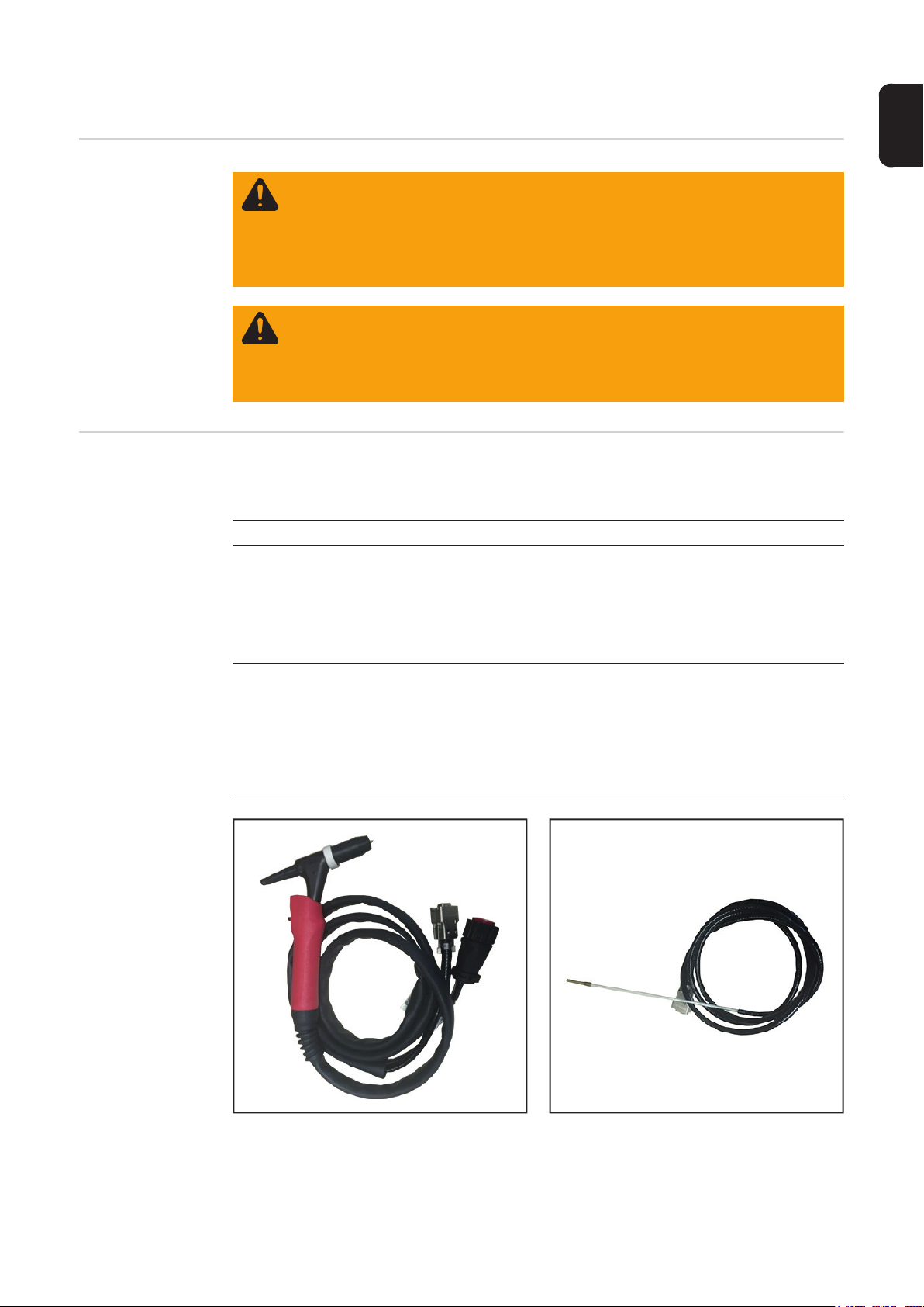
1 x Fronius WIG-Schweißbrenner (1)
Artikel-Nr. F9027014
1 x Fronius WIG-Schweißbrenner (2)
3
Page 4

Lieferumfang
MobileCase StandUp
(1) (3) (4)(2)
(1) (3)(2)
Erforderliches
Werkzeug
(1) 4 x SUB-D Abstandhalter, Artikel-Nr. F9025003
(2) 2 x Montageplatte, Artikel-Nr. F9018046
(3) 1 x Anschlussplatte Kunststoff, Artikel-Nr.
F9020040
- Kreuzschlitz-Schraubendreher (PH2)
- Gabelschlüssel (5 mm)
- Gabelschlüssel (5,5 mm)
- Gabelschlüssel (10 mm)
(1) 2 x SUB-D Abstandhalter, Artikel-Nr. F9025003
(2) 1 x Montageplatte, Artikel-Nr. F9018046
(3) 1 x Anschlussplatte Kunststoff, Artikel-Nr.
F9020041
(4) 2 x Versteifung, Artikel-Nr. F9018047
4 x Kreuzschraube M3 x 6 mm, Artikel-Nr. F7200336
(nicht abgebildet)
4
Page 5

WIG Virtual Welding in MobilCase einbauen
DE
Metall-Anschlussplatte entfernen
(MobileCase)
Sämtliche Kabel von den externen An-
1
schlüssen abstecken
Rändelschrauben lösen
2
Stecker abstecken
3
WICHTIG! Vor dem Abschließen der internen Leitungen die Anschlussfolge / Positionen der Steckverbindungen notieren oder
kennzeichnen.
Falls Rändelschrauben vorhanden
5
5
5
5
5
5
4
sind:
Rändelschrauben lösen
Sämtliche Kabel von den internen An-
5
schlüssen abstecken
(4) (4) (4)(3)(5) (4)
8
10
7
(1) (1)(2)
11
12
12
11
11
11
11
(6)
(6)
4 Sechskant-Muttern (1) entfernen
6
Steckanschluss Schweißbrenner (2)
7
heraus nehmen
Falls vorhanden:
8
Sechskant-Mutter vom Setup-Taster
(3) abschrauben
7 Kreuzschrauben (4) entfernen
9
Anschlussblech (5) entnehmen
10
Bei sämtlichen Anschlüssen die
11
Schrauben entfernen und die Anschlüsse vom Anschlussblech entfernen
Bei den Kupplungen (6) die Abstand-
12
halter abschrauben und Kupplungen
abnehmen
5
Page 6

Kunststoff-Anschlussplatte entfernen
(MobileCase)
Sämtliche Kabel von den externen An-
1
schlüssen abstecken
Rändelschrauben lösen
2
Stecker abstecken
3
3
3
3
1
WICHTIG! Vor dem Abschließen der internen Leitungen die Anschlussfolge / Positionen der Steckverbindungen notieren oder
kennzeichnen.
Falls Rändelschrauben vorhanden
5
5
5
5
5
5
4
sind:
Rändelschrauben lösen
Sämtliche Kabel von den internen An-
5
schlüssen abstecken
(1)
7
(1)(2)(1)
(4) (4)
10
(3)(4) (5)
8
4 Sechskant-Muttern (1) entfernen
6
Steckanschluss Schweißbrenner (2)
7
heraus nehmen
Falls vorhanden:
8
Sechskant-Mutter vom Setup-Taster
(3) abschrauben
7 Kreuzschrauben (4) entfernen
9
Kunststoff-Anschlussplatte (5) entneh-
10
men
2 VGA-Anschlüsse (6) ausbauen
11
(6) (6)
Außenansicht
6
Page 7
Innenansicht
DE
(6)(6)
WIG Virtual Welding in MobileCase einbauen
Arbeitsschritte 1 - 4 nur, wenn die 15-polige DVI-Buchse und der 15-polige D-SUB Anschluss noch nicht auf einer Montageplatte montiert sind.
15-polige DVI-Buchse (3) gemäß Ab-
1
bildung in die Montageplatte (2) einsetzen
(1)
15-polige DVI-Buchse (3) mit 2 SUB-D
2
Abstandhaltern (1) fixieren
(2)
(3)
(1)
15-polige DVI-Buchse auf Montageplatte
15-poligen D-SUB Anschluss (4) ge-
3
mäß Abbildung in die Montageplatte
(2) einsetzen
(1)
15-poligen D-SUB Anschluss (4) mit 2
4
SUB-D Abstandhaltern (1) und 2
(2)
Sechskant-Muttern fixieren
(4)
(1)
15-poliger D-SUB Anschluss auf Montageplatte
7
Page 8

(5)
(5)
(5)
HINWEIS! Die Anschlussplatte Kunststoff hat auf der Außenseite eine genarbte
Oberfläche und auf der Innenseite eine glatte Oberfläche.
Montageplatten (2) (mit DVI-Buchse
(2)
5
und mit D-SUB Anschluss) gemäß Abbildung an der Außenseite in die Anschlussplatte einsetzen
Montageplatten (2) mit je 4 Kreuz-
6
schrauben M3 x 6 mm an der Außenseite befestigen
Alle anderen Anschlüsse an der Au-
7
ßenseite einsetzen und festschrauben
(5)
(2)
(6) (6)
Anschlussplatte - Außenseite
(6) (6)
Anschlussplatte - Innenseite
WICHTIG! Die VGA-Anschlüsse (6) werden an der Innenseite eingesetzt und verschraubt!
2 VGA-Anschlüsse (6) gemäß Abbil-
8
dung an der Innenseite einsetzen und
festschrauben
Anschlussplatte einsetzen und mit 7
(7) (7) (7)
9
Kreuzschrauben (7) befestigen
Steckanschluss Schweißbrenner (8)
10
einsetzen
Steckanschluss Schweißbrenner (8)
11
mit 4 Schrauben M3 x 15 mm (9) und 4
selbstsichernden Sechskant-Muttern
befestigen
Falls vorhanden, Setup-Taster in Pos.
12
(10) einsetzen und verschrauben
(8)
(9) (10)(9)
Anschlussplatte - Innenseite
8
Page 9
(14)
(13)(12)(11)
Anschlussplatte - Innenseite
Kabel an den richtigen Positionen an-
13
schließen:
(16) (17)(15)
(11) LAN
DE
(12) USB
(13) Schweißbrenner (Polhemus 1)
(14) Kopfsensor/Schweißzusatz Sensor (Polhemus 2)
(15) 3D-Brille (alt)
(16) Werktisch
(17) 3D-Brille Scout
Kabel an den richtigen Positionen an-
14
schließen:
(19) Sensor Werktisch
(20) Kopfsensor/Schweißzusatz Sensor (Polhemus 2)
(21) Schweißbrenner (Polhemus 1)
(22) Schweißbrenner (LocalNet)
Anschlussplatte - Außenseite
(22)(21)(20)(19)
9
Page 10

WIG Virtual Welding in StandUp einbauen
Metall-Anschlussplatte entfernen (StandUp)
1
1
(1) (1)(2)
Sämtliche Kabel von den externen An-
1
schlüssen abstecken
1
Rändelschrauben und Schrauban-
2
schluss lösen
Stecker abstecken
3
WICHTIG! Vor dem Abschließen der internen Leitungen die Anschlussfolge / Positionen der Steckverbindungen notieren oder
kennzeichnen.
Falls Rändelschrauben vorhanden
4
sind:
Rändelschrauben lösen
Sämtliche Kabel von den internen An-
5
schlüssen abstecken
4 Kreuzschrauben (1) entfernen
6
Anschlussblech (2) entnehmen
7
12
(6)
11
11
(1)(1)
4 Kreuzschrauben (3) und Sechskant-
8
Muttern entfernen
Steckanschluss Schweißbrenner (4)
9
heraus nehmen
Falls vorhanden:
10
Sechskant-Mutter vom Setup-Taster
(5) abschrauben und Taster entnehmen
(3) (3)(4)(5)
Bei sämtlichen Anschlüssen die
11
Schrauben entfernen und die Anschlüsse vom Anschlussblech entfernen
Bei den Kupplungen (6) die Abstand-
12
halter abschrauben und Kupplungen
abnehmen
10
Page 11

Kunststoff-Anschlussplatte entfernen (StandUp)
Sämtliche Kabel von den externen An-
1
schlüssen abstecken
1
1
1
Rändelschrauben lösen
2
Stecker abstecken
3
DE
WICHTIG! Vor dem Abschließen der inter-
nen Leitungen die Anschlussfolge / Positio-
5
5
5
nen der Steckverbindungen notieren oder
kennzeichnen.
Falls Rändelschrauben vorhanden
4
sind:
Rändelschrauben lösen
Sämtliche Kabel von den internen An-
5
schlüssen abstecken
6 Kreuzschrauben (1) entfernen
6
(1)(1) (2) (3)
Anschlussblech (3) entnehmen
7
2 Versteifungen (2) abnehmen
8
WIG Virtual Welding in StandUp
einbauen
4 Kreuzschrauben (3) und Sechskant-
9
(4) (4)(5)(6)
Muttern entfernen
Steckanschluss Schweißbrenner (4)
10
heraus nehmen
Falls vorhanden:
11
Sechskant-Mutter vom Setup-Taster
(5) abschrauben und Taster entnehmen
2 VGA-Anschlüsse (7) ausbauen
12
(7) (7)
Außenansicht
Arbeitsschritte 1 - 2 nur, wenn der 15-polige D-SUB Anschluss noch nicht auf einer Montageplatte montiert ist.
11
Page 12

(1)
(2)
(4)
(1)
15-poliger D-SUB Anschluss auf Montageplatte
HINWEIS! Die Anschlussplatte Kunststoff hat auf der Außenseite eine genarbte
Oberfläche und auf der Innenseite eine glatte Oberfläche.
(2)
(3) (3)
(5) (5)
a)
(3)
(5) (5)
(2)
b)
15-poligen D-SUB Anschluss (4) ge-
1
mäß Abbildung in die Montageplatte
(2) einsetzen
15-poligen D-SUB Anschluss (4) mit 2
2
SUB-D Abstandhaltern (1) und 2
Sechskant-Muttern fixieren
Montageplatte (2) (mit D-SUB An-
3
schluss) gemäß Abbildung an der Außenseite in die Anschlussplatte
einsetzen
Montageplatte (2) mit je 4 Kreuz-
4
schrauben M3 x 6 mm (3) an der Außenseite befestigen
2 VGA-Anschlüsse (5) gemäß Abbil-
5
dung einsetzen und an der Außenseite
festschrauben
a) Außenseite (genarbte Oberfläche)
b) Innenseite (glatte Oberfläche)
(11) (12)(10)(9)
Anschlussplatte - Innenseite
(6) (6)
(6) (6)(7)(8)
Steckanschluss Schweißbrenner (7)
6
einsetzen
Steckanschluss Schweißbrenner (7)
7
mit 4 Schrauben M3 x 15 mm (6) und 4
selbstsichernden Sechskant-Muttern
befestigen
Falls vorhanden, Setup-Taster in Pos.
8
(8) einsetzen und verschrauben
Kabel an den richtigen Positionen an-
9
schließen:
(9) Sensor Werkstück-Halterung
(10) Kopfsensor/Schweißzusatz Sensor
(11) Schweißbrenner 1
(12) Schweißbrenner 2
12
Page 13

(15)(14)(13) (13) (13)
(13)(13)(13)
Anschlussplatte (15) mit 2 Versteifun-
10
gen (14) einsetzen und mit 6 Kreuzschrauben (13) befestigen
Kabel an den richtigen Positionen an-
11
schließen:
(16) Werktisch
(17) Kopfsensor/Schweißzusatz Sensor (Polhemus 2)
(18) Schweißbrenner (Polhemus 1)
(19) Schweißbrenner
DE
Anschlussplatte - Außenseite
(19)(18)(17)(16)
13
Page 14

14
Page 15

General
Safety
General To operate the 2-part Fronius TIG welding torch, the following steps need to be carried out:
MobileCase StandUp
Device with metal connection plate:
- Remove the metal connection plate
- Replace the metal connection plate
- Install the plastic connection plate
Device with plastic connection plate:
- Remove the plastic connection plate
- Remove 2 x 15-pin VGA connections
- Install the plastic connection plate
WARNING! An electric shock can be fatal. Before opening the device
- Turn the mains switch to the "O" position
- Unplug the machine from the mains
- Put up an easy-to-understand warning sign to stop anybody inadvertently
switching it back on again
- Using a suitable measuring instrument, check to make sure that electrically
charged components (e.g. capacitors) have discharged
WARNING! Work that is carried out incorrectly can cause serious injury and damage. The following activities must only be carried out by trained and qualified personnel. Read the "Safety rules" chapter in the power source and system
components operating instructions.
Device with metal connection plate:
- Remove the metal connection plate
- Replace the metal connection plate
with the plastic connection plate from
the conversion kit
and refit from the other side
with the plastic connection plate from
the conversion kit
- Install the plastic connection plate
Device with plastic connection plate:
- Remove the plastic connection plate
- Remove 2 x 15-pin VGA connections
and refit from the other side
- Install the plastic connection plate
with 2 braces
EN
Scope of supply
1 x Fronius TIG welding torch (1)
Item no. F9027014
MobileCase StandUp
1 x Fronius TIG welding torch (2)
15
Page 16

(1) (3)(2)
(1) (3) (4)(2)
(1) 4 x SUB-D spacers, item no. F9025003
(2) 2 x mounting plates, item no. F9018046
(3) 1 x plastic connection plate, item no. F9020040
Tools required - Philips screwdriver (PH2)
- Flat spanner (5 mm)
- Flat spanner (5.5 mm)
- Flat spanner (10 mm)
(1) 2 x SUB-D spacers, item no. F9025003
(2) 1 x mounting plate, item no. F9018046
(3) 1 x plastic connection plate, item no. F9020041
(4) 2 x braces, item no. F9018047
4 x Philips screws M3 x 6 mm, item no. F7200336 (not
shown)
16
Page 17

Installing TIG Virtual Welding in the MobileCase
Removing the
metal connection
plate (MobileCase)
Unplug all cables from the external
1
connections
EN
Remove the knurled screws
2
Disconnect the plugs
3
IMPORTANT! Before disconnecting the internal leads, note down or label the connection sequence / positions of the plug
connections.
If knurled screws are present:
5
5
5
5
5
5
4
undo knurled screws
Unplug all cables from the internal
5
connections
(4) (4) (4)(3)(5) (4)
8
10
7
(1) (1)(2)
11
11
11
12
(6)
Remove the 4 hexagon nuts (1)
6
Take out the welding torch connection
7
socket (2)
If present:
8
unscrew the hexagon nut from the Setup button (3)
Remove the 7 Philips screws (4)
9
Remove the connection plate (5)
10
Remove the screws from all connec-
11
tions and remove the connections from
the connection plate
Unscrew the spacers from the cou-
12
plings (6) and remove the couplings
11
11
12
(6)
17
Page 18

Removing the
plastic connection plate (MobileCase)
Unplug all cables from the external
1
connections
Remove the knurled screws
2
Disconnect the plugs
3
3
3
3
1
IMPORTANT! Before disconnecting the internal leads, note down or label the connection sequence / positions of the plug
connections.
If knurled screws are present:
5
5
5
5
5
5
4
undo knurled screws
Unplug all cables from the internal
5
connections
(1)
7
(1)(2)(1)
(4) (4)
10
(3)(4) (5)
8
Remove the 4 hexagon nuts (1)
6
Take out the welding torch connection
7
socket (2)
If present:
8
unscrew the hexagon nut from the Setup button (3)
Remove the 7 Philips screws (4)
9
Remove the plastic connection plate
10
(5)
Remove the 2 VGA connections (6)
11
18
(6) (6)
Exterior view
Page 19

Interior view
EN
(6)(6)
Installing TIG Virtual Welding in
the MobileCase
Only follow steps 1 - 4 if the 15-pin DVI socket and the 15-pin D-SUB connection socket
are not yet fitted to mounting plates.
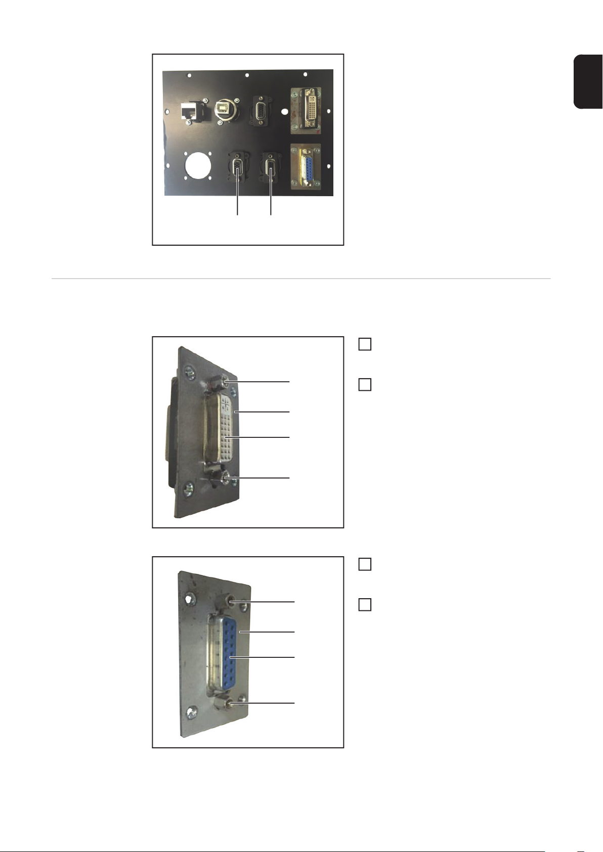
Insert the 15-pin DVI socket (3) into the
1
mounting plate (2) as shown
Secure the 15-pin DVI socket (3) with 2
(1)
2
SUB-D spacers (1)
(2)
(3)
(1)
15-pin DVI socket on mounting plate
Insert the 15-pin D-SUB connection
3
socket (4) into the mounting plate (2)
as shown
(1)
Secure the 15-pin D-SUB connection
4
socket (4) with 2 SUB-D spacers (1)
(2)
and 2 hexagon nuts
(4)
(1)
15-pin D-SUB connection socket on mounting plate
19
Page 20

(5)
(5)
(5)
NOTE! The plastic connection plate has a grained surface on the exterior and a
smooth surface on the interior.
Insert the mounting plates (2) (with DVI
(2)
5
socket and D-SUB connection socket)
into the exterior of the connection plate
as shown
Secure each mounting plate (2) to the
6
exterior with 4 Philips M3 x 6 mm
screws
Fit all other connections to the exterior
7
and secure with screws
(5)
(2)
(6) (6)
Connection plate - exterior
(6) (6)
Connection plate - interior
IMPORTANT! The VGA connections (6)
are fitted and screwed to the interior.
Fit the 2 VGA connections (6) to the in-
8
terior as shown and secure with
screws
20
(7) (7) (7)
(8)
(9) (10)(9)
Connection plate - interior
Insert the connection plate and secure
9
using 7 Philips screws (7)
Insert the welding torch connection so-
10
cket (8)
Secure the welding torch connection
11
socket (8) with 4 M3 x 15 mm screws
(9) and 4 self-locking hexagon nuts
If present, insert the Setup button into
12
pos. (10) and secure with screws
Page 21

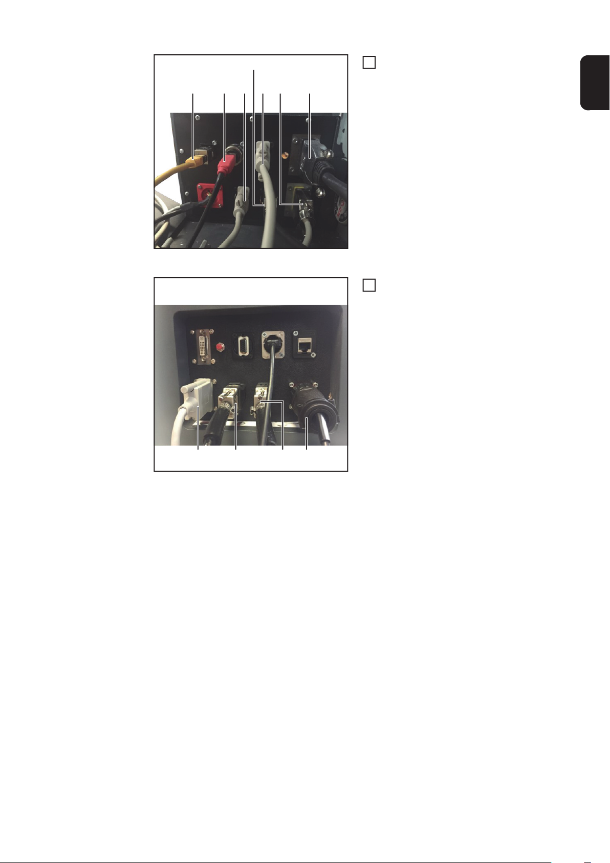
(13)(12)(11)
Connection plate - interior
(14)
Connect the cables to the correct so-
13
ckets:
(16) (17)(15)
(11) LAN
(12) USB
(13) Welding torch (Polhemus 1)
(14) Head sensor/filler material
sensor (Polhemus 2)
(15) 3D glasses (old)
EN
(16) Work table
(17) 3D glasses (Scout)
Connect the cables to the correct so-
14
ckets:
(19) Work table sensor
(20) Head sensor/filler material
sensor (Polhemus 2)
(21) Welding torch (Polhemus 1)
(22) Welding torch (LocalNet)
Connection plate - exterior
(22)(21)(20)(19)
21
Page 22

Installing TIG Virtual Welding in the StandUp
Removing the
metal connection
plate (StandUp)
1
1
(1) (1)(2)
Unplug all cables from the external
1
connections
1
Undo the knurled screws and screw
2
connection
Disconnect the plugs
3
IMPORTANT! Before disconnecting the internal leads, note down or label the connection sequence / positions of the plug
connections.
If knurled screws are present:
4
undo knurled screws
Unplug all cables from the internal
5
connections
Remove the 4 Philips screws (1)
6
Remove the connection plate (2)
7
12
(6)
11
11
(1)(1)
Remove the 4 Philips screws (3) and
8
hexagon nuts
Take out the welding torch connection
9
socket (4)
If present:
10
unscrew the hexagon nut from the Setup button (5) and remove the button
(3) (3)(4)(5)
Remove the screws from all connec-
11
tions and remove the connections from
the connection plate
Unscrew the spacers from the cou-
12
plings (6) and remove the couplings
22
Page 23

Removing the
plastic connection plate (StandUp)
Unplug all cables from the external
1
connections
1
1
1
Remove the knurled screws
2
Disconnect the plugs
3
EN
IMPORTANT! Before disconnecting the in-
ternal leads, note down or label the connec-
5
5
5
tion sequence / positions of the plug
connections.
If knurled screws are present:
4
undo knurled screws
Unplug all cables from the internal
5
connections
Remove the 6 Philips screws (1)
6
(1)(1) (2) (3)
Remove the connection plate (3)
7
Remove the 2 braces (2)
8
Installing TIG Virtual Welding in
the StandUp
Remove the 4 Philips screws (3) and
9
(4) (4)(5)(6)
hexagon nuts
Take out the welding torch connection
10
socket (4)
If present:
11
unscrew the hexagon nut from the Setup button (5) and remove the button
Remove the 2 VGA connections (7)
12
(7) (7)
Exterior view
Only follow steps 1 - 2 if the 15-pin D-SUB connection socket is not yet fitted to a mounting
plate.
23
Page 24

(1)
(2)
(4)
(1)
15-pin D-SUB connection socket on mounting plate
NOTE! The plastic connection plate has a grained surface on the exterior and a
smooth surface on the interior.
(2)
(3) (3)
(5) (5)
a)
(3)
(5) (5)
(2)
Insert the 15-pin D-SUB connection
1
socket (4) into the mounting plate (2)
as shown
Secure the 15-pin D-SUB connection
2
socket (4) with 2 SUB-D spacers (1)
and 2 hexagon nuts
Insert the mounting plate (2) (with D-
3
SUB connection socket) into the exterior of the connection plate as shown
Secure the mounting plate (2) to the
4
exterior with 4 Philips M3 x 6 mm
screws (3)
Fit the 2 VGA connections (5) to the ex-
5
terior as shown and secure with
screws
b)
a) Exterior (grained surface)
b) Interior (smooth surface)
Insert the welding torch connection so-
(6) (6)
6
cket (7)
Secure the welding torch connection
7
socket (7) with 4 M3 x 15 mm screws
(6) and 4 self-locking hexagon nuts
If present, insert the Setup button into
8
pos. (8) and secure with screws
(6) (6)(7)(8)
Connect the cables to the correct so-
9
ckets:
(9) Workpiece holder sensor
(10) Head sensor/filler material
sensor
(11) Welding torch 1
(12) Welding torch 2
(11) (12)(10)(9)
24
Connection plate - interior
Page 25

(15)(14)(13) (13) (13)
(13)(13)(13)
Insert the connection plate (15) with 2
10
braces (14) and secure with 6 Philips
screws (13)
Connect the cables to the correct so-
11
ckets:
(16) Work table
(17) Head sensor/filler material
sensor (Polhemus 2)
(18) Welding torch (Polhemus 1)
(19) Welding torch
EN
Connection plate - exterior
(19)(18)(17)(16)
25
Page 26

26
Page 27

EN
27
Page 28

FRONIUS INTERNATIONAL GMBH
Froniusplatz 1, A-4600 Wels, Austria
Tel: +43 (0)7242 241-0, Fax: +43 (0)7242 241-3940
E-Mail: sales@fronius.com
www.fronius.com
www.fronius.com/addresses
Under http://www.fronius.com/addresses you will find all addresses
of our Sales & service partners and Locations
 Loading...