

Page 1

Operating
In
TIG Grinder
structions
Bedienungsanleitung
DE
Operating instructions
EN
Instructions de service
FR
Manual de instrucciones
ES
Istruzioni per l'uso
IT
42,0410,1815 006-15112022
Page 2

Page 3

Inhaltsverzeichnis
Sicherheitsvorschriften 5
Erklärung Sicherheitshinweise 5
Allgemeines 5
Besondere Gefahrenstellen 6
Bestimmungsgemäße Verwendung 6
Umgebungsbedingungen 6
Verpflichtungen des Betreibers 7
Qualifiziertes und geschultes Fachpersonal 7
Verpflichtungen des Personals 7
Wartung und Instandsetzung 7
Urheberrecht 7
Allgemeines 8
Beschreibung des Gerätes 8
Lieferumfang 8
Bestimmungsgemäße Verwendung 9
Bedienelemente und Anschlüsse 10
Bedienelemente und Anschlüsse 10
Installation 11
Sicherheit 11
Längenanschlag montieren 11
Handgriff für Trenneinrichtung montieren 12
Elektrodenhalter zusammenbauen 12
Schleifflüssigkeit einfüllen 13
Führungsbuchse einstellen 13
Inbetriebnahme 14
Sicherheit 14
Aufstellbestimmungen 14
Netzanschluss 14
Inbetriebnahme 14
Elektrode schleifen 15
Allgemeines 15
Elektrode vorbereiten 15
Elektrode schleifen 16
Elektrodenspitze abtrennen 17
Allgemeines 17
Elektrodenführung wechseln 17
Vorbereitung 17
Elektrodenspitze abtrennen 18
Elektrode mit definierter Länge herstellen 19
Allgemeines 19
Vorbereitung 19
Elektrode mit definierter Länge herstellen 20
Elektrode schleifen 20
Herstellen einer Elektrode kürzer als 25 mm 22
Allgemeines 22
Elektrode vorbereiten 22
Elektrode schleifen 23
Herstellen einer Elektrode kürzer als 25 mm 24
Herstellen einer abgestumpften Elektrodenspitze 25
Allgemeines 25
Vorbereitung 25
Herstellen einer abgestumpften Elektrodenspitze 25
Fehlerdiagnose 27
Fehler an der Elektrode 27
Fehler am Gerät 28
Fehlerbehebung 29
Sicherheit 29
Fehlerbehebeung Übersicht 29
Benötigte Werkzeuge und Hilfsmittel 29
Scheibenverschleiß ausgleichen 29
DE
3
Page 4

Schleifspur wechseln 30
Schleifflüssigkeit ablassen 30
Deckplatte entfernen 32
Schleifscheibe wechseln 32
Trennscheibe wechseln 33
Deckplatte montieren 33
Schleifflüssigkeit einfüllen 34
Batterie der Digitalanzeige wechseln 35
Pflege, Wartung und Entsorgung 37
Sicherheit 37
Allgemeines 37
Vor jeder Inbetriebnahme 37
Alle 6 Monate 37
Entsorgung 37
Technische Daten 38
TIG Grinder 38
4
Page 5

Sicherheitsvorschriften
DE
Erklärung Sicherheitshinweise
GEFAHR!
Bezeichnet eine unmittelbar drohende Gefahr.
Wenn sie nicht gemieden wird, sind Tod oder schwerste Verletzungen die Fol-
▶
ge.
WARNUNG!
Bezeichnet eine möglicherweise gefährliche Situation.
Wenn sie nicht gemieden wird, können Tod und schwerste Verletzungen die
▶
Folge sein.
VORSICHT!
Bezeichnet eine möglicherweise schädliche Situation.
Wenn sie nicht gemieden wird, können leichte oder geringfügige Verletzun-
▶
gen sowie Sachschäden die Folge sein.
HINWEIS!
Bezeichnet die Möglichkeit beeinträchtigter Arbeitsergebnisse und von
Schäden an der Ausrüstung.
Allgemeines Das Gerät ist nach dem Stand der Technik und den anerkannten sicherheitstech-
nischen Regeln gefertigt. Dennoch drohen bei Fehlbedienung oder Missbrauch
Gefahr für
Leib und Leben des Bedieners oder Dritte,
-
das Gerät und andere Sachwerte des Betreibers,
-
die effiziente Arbeit mit dem Gerät.
-
Alle Personen, die mit der Inbetriebnahme, Bedienung, Wartung und Instandhaltung des Gerätes zu tun haben, müssen
entsprechend qualifiziert sein,
-
diese Bedienungsanleitung vollständig lesen und genau befolgen.
-
Die Bedienungsanleitung ist ständig am Einsatzort des Gerätes aufzubewahren.
Ergänzend zur Bedienungsanleitung sind die allgemein gültigen sowie die örtlichen Regeln zu Unfallverhütung und Umweltschutz zu beachten.
Alle Sicherheits- und Gefahrenhinweise am Gerät
in lesbarem Zustand halten
-
nicht beschädigen
-
nicht entfernen
-
nicht abdecken, überkleben oder übermalen.
-
Die Positionen der Sicherheits- und Gefahrenhinweise am Gerät, entnehmen Sie
dem Kapitel „Allgemeines“ der Bedienungsanleitung Ihres Gerätes.
Störungen, die die Sicherheit beeinträchtigen können, vor Inbetriebnahme des
Gerätes beseitigen.
Es geht um Ihre Sicherheit!
5
Page 6

Besondere Gefahrenstellen
Hände, Haare, Kleidungsstücke und Werkzeuge von beweglichen Teilen fernhalten, wie zum Beispiel:
Zahnrädern
-
Rollen
-
Wellen
-
Gelenke
-
Nicht in rotierende Antriebsteile greifen.
Quetschgefahr!
Hände und andere Körperteile nicht zwischen pressende Teile geben.
Schnittgefahr!
Beim Hantieren mit scharfkantigen Gegenständen Schutz-Handschuhe tragen.
Abdeckungen und Seitenteile dürfen nur für die Dauer von Wartungs- und Reparaturarbeiten geöffnet / entfernt werden.
Während des Betriebes
Sicherstellen, dass alle Abdeckungen geschlossen und sämtliche Seitenteile
-
ordnungsgemäß montiert sind.
Alle Abdeckungen und Seitenteile geschlossen halten.
-
Bestimmungsgemäße Verwendung
Umgebungsbedingungen
Das Gerät ist ausschließlich für den Einsatz im Sinne der bestimmungsgemäßen
Verwendung zu benutzen.
Eine andere oder darüber hinaus gehende Benutzung gilt als nicht bestimmungsgemäß. Für hieraus entstandene Schäden haftet der Hersteller nicht.
Zur bestimmungsgemäßen Verwendung gehört auch
das vollständige Lesen und Befolgen aller Hinweise, sowie aller Sicherheits-
-
und Gefahrenhinweise aus der Bedienungsanleitung
die Einhaltung aller Inspektions- und Wartungsarbeiten
-
die Installation gemäß Bedienungsanleitung
-
Betrieb oder Lagerung des Gerätes außerhalb des angegebenen Bereiches gilt
als nicht bestimmungsgemäß. Für hieraus entstandene Schäden haftet der Hersteller nicht.
Temperaturbereich der Umgebungsluft:
beim Betrieb: + 5 °C bis + 40 °C (41 °F bis 104 °F)
-
bei Transport und Lagerung: -15 °C bis +55 °C (5 °F bis 131 °F)
-
Relative Luftfeuchtigkeit:
bis 50 % bei 40 °C (104 °F)
-
bis 80 % bei 20 °C (68 °F)
-
Umgebungsluft: frei von Staub, Säuren, korrosiven Gasen oder Substanzen, usw.
6
Page 7

Verpflichtungen
des Betreibers
Der Betreiber verpflichtet sich, nur Personen am Gerät arbeiten zu lassen, die
mit den grundlegenden Vorschriften über Arbeitssicherheit und Unfall-
-
verhütung vertraut und in die Handhabung des Gerätes eingewiesen sind
diese Bedienungsanleitung, insbesondere das Kapitel „Sicherheitsvorschrif-
-
ten“ gelesen, verstanden und dies durch ihre Unterschrift bestätigt haben
entsprechend den Anforderungen an die Arbeitsergebnisse ausgebildet sind.
-
Das sicherheitsbewusste Arbeiten des Personals ist in regelmäßigen Abständen
zu überprüfen.
DE
Qualifiziertes
und geschultes
Fachpersonal
Verpflichtungen
des Personals
Wartung und Instandsetzung
Die Inbetriebnahme und Bedienung des Gerätes darf nur von qualifiziertem
Fachpersonal durchgeführt werden, welches eine entsprechende Einschulung
von der Fa. Fronius erhalten hat. Daher sind die Informationen in dieser Bedienungsanleitung auch nur für diese Personen bestimmt. Führen Sie keine anderen
als die in der Bedienungsanleitung angeführten Tätigkeiten aus. Das gilt auch,
wenn sie dafür qualifiziert sind.
Alle Personen, die mit Arbeiten am Gerät beauftragt sind, verpflichten sich, vor
Arbeitsbeginn
die grundlegenden Vorschriften über Arbeitssicherheit und Unfallverhütung
-
zu befolgen
diese Bedienungsanleitung, insbesondere das Kapitel „Sicherheitsvorschrif-
-
ten“ zu lesen und durch ihre Unterschrift zu bestätigen, dass sie diese verstanden haben und befolgen werden.
Vor Verlassen des Arbeitsplatzes sicherstellen, dass auch in Abwesenheit keine
Personen- oder Sachschäden auftreten können.
Reparatur- und Instandsetzungsarbeiten dürfen ausschließlich durch autorisierte Personen erfolgen. Nur Original-Ersatz- und Verschleißteile verwenden (gilt
auch für Normteile). Bei fremdbezogenen Teilen ist nicht gewährleistet, dass diese beanspruchngs- und sicherheitsgerecht konstruiert und gefertigt sind.
Ohne Genehmigung des Herstellers keine Veränderungen, Ein- oder Umbauten
am Gerät vornehmen.
Die Anleitungen für die Wartung entbinden nicht von der Notwendigkeit, das
Gerät sorgfältig zu überwachen und auftretende Störungen sofort zu beseitigen.
Für Folgeschäden, die auf Grund mangelhaft durchgeführter Wartung oder falscher Bedienung entstehen, übernimmt der Hersteller keine Garantie.
Urheberrecht Das Urheberrecht an dieser Bedienungsanleitung verbleibt beim Hersteller.
Text und Abbildungen entsprechen dem technischen Stand bei Drucklegung.
Änderungen vorbehalten. Der Inhalt der Bedienungsanleitung begründet keinerlei Ansprüche seitens des Käufers. Für Verbesserungsvorschläge und Hinweise
auf Fehler in der Bedienungsanleitung sind wir dankbar.
7
Page 8
Allgemeines
(6)
(1)
(7)
(8)
(9)
(10)
(11)
(2)
(3)
(4)
(5)
Beschreibung
des Gerätes
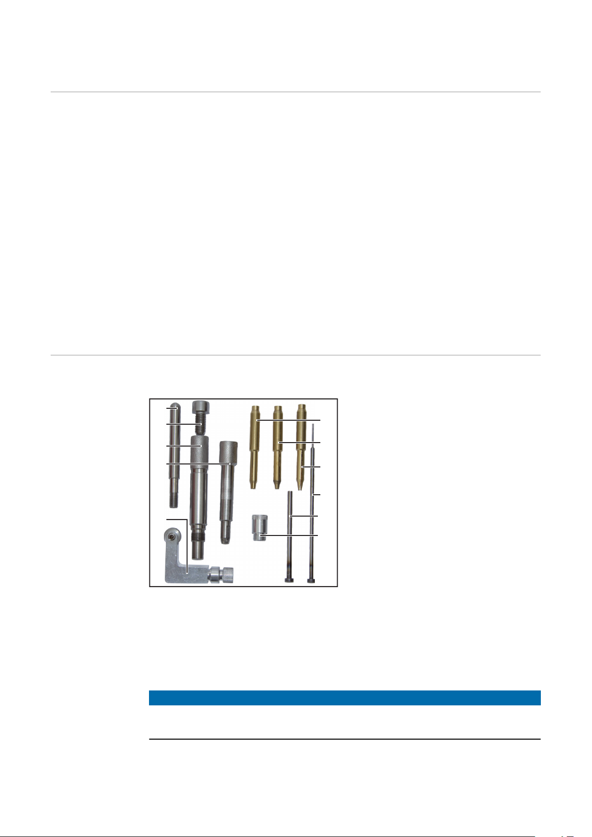
Lieferumfang Zusätzlich zum Grundgerät sind folgende Elemente im Lieferumfang enthalten:
Das Gerät dient zum Anspitzen und Abtrennen von Wolframnadeln welche als
Elektroden für WIG-Schweißbrenner verwendet werden.
Der Winkel der Spitze ist stufenlos einstellbar und wird digital angezeigt.
Mit Hilfe der Trenneinrichtung können Elektroden mit beliebiger Mindestlänge
hergestellt werden.
Der Schleifvorgang erfolgt an der flachen Seite der Schleifscheibe in Längsrichtung der Elektrode. Dadurch wird eine optimale Ausbildung der Spitze erreicht.
Um die Standzeit der Schleifscheibe zu erhöhen können 3 Schleifspuren ausgewählt werden.
Mit dem Elektrodenhalter werden die Elektroden beim Schleifvorgang exakt positioniert. Das gewährleistet eine präzise und wiederholbare Herstellung der Elektrodenspitze.
Für jeden Elektrodendurchmesser gibt es eine eigene Spannhülse um einen festen Sitz im Elektrodenhalter zu gewährleisten.
Durch die verwendete Schleifflüssigkeit und den Auffangbehälter werden
Schleifstaub-Emissionen vermieden.
(1) Handgriff für Trenneinrichtung
(2) Schraube M10 für Anschlagstift
(3) Elektrodenhalter-Hinterteil
(4) Elektrodenhalter-Vorderteil
(5) Längenanschlag
(6) Spannhülse 3,2 mm
(7) Spannhülse 2,4 mm
(8) Spannhülse 1,6 mm
(9) Anschlagstift für 30 mm Elek-
trode
(10) Anschlagstift für 92 mm Elek-
trode
(11) Elektrodenführung 1,0 - 1,6
mm
ohne Abbildung:
250 ml Schleifflüssigkeit
-
500 ml Schleifflüssigkeit
-
Elektrodenführung 2,4 - 3,2 mm
-
(bereits an der Rückseite der
HINWEIS!
Die Sicherheitsdatenblätter für die Schleifflüssigkeit können bei Bedarf beim
Hersteller angefordert werden.
8
Trenneinrichtung montiert)
Page 9

Bestimmungsgemäße Verwendung
Das Gerät ist ausschließlich für das Schleifen und/oder Abtrennen von Wolframelektroden vorgesehen. Eine andere oder darüber hinausgehende Verwendung
gilt nicht als bestimmungsgemäß. Für hieraus entstehende Schäden haftet der
Hersteller nicht
DE
9
Page 10
Bedienelemente und Anschlüsse
(1)
(9)
(2)
(3)
(4)
(5)
(6)
(7)
(10)
(11)
(13)
(12)
(8)
(15)
(16)
(16)
(17)
(18)
(14)
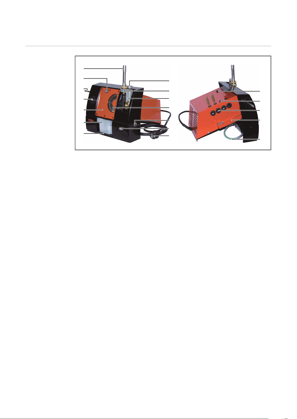
Bedienelemente
und Anschlüsse
(1) Elektrodenhalter
(2) Digitalanzeige
(3) Handgriff für Trenneinrichtung
(4) Führungsbuchse der Trennein-
richtung
(5) Deckplatte
(6) Tank für die Schleifflüssigkeit
(7) Keil zum Fixieren des Tanks
(8) Rändelschraube zum Fixieren
der Winkelverstellung
(9) Führungsbuchse der Schleif-
einrichtung
(10) Winkelverstellung
(11) Füllstands-Anzeige
(12) Führungsbuchse des Längen-
anschlages
(13) Längenanschlag
(14) Netzstecker
(15) Hauptschalter
(16) Werkzeug-Aufbewahrung
(17) Sammeltasse
(18) Ablass-Schlauch zum Entlee-
ren des Tanks
10
Page 11
Installation
(1)
(2)
(3)
(4)
(5)
DE
Sicherheit
WARNUNG!
Gefahr durch Fehlbedienung und fehlerhaft durchgeführte Arbeiten.
Schwere Personen- und Sachschäden können die Folge sein.
Alle in diesem Dokument beschriebenen Arbeiten und Funktionen dürfen
▶
nur von technisch geschultem Fachpersonal ausgeführt werden.
Dieses Dokument vollständig lesen und verstehen.
▶
Sämtliche Sicherheitsvorschriften und Benutzerdokumentationen dieses
▶
Gerätes und aller Systemkomponenten lesen und verstehen.
WARNUNG!
Gefahr durch elektrischen Strom.
Schwere Personen- und Sachschäden können die Folge sein.
Vor Beginn der Arbeiten alle beteiligten Geräte und Komponenten ausschal-
▶
ten und von Stromnetz trennen.
Alle beteiligten Geräte und Komponenten gegen Wiedereinschalten sichern.
▶
Nach dem Öffnen des Gerätes mit Hilfe eines geeigneten Messgerätes si-
▶
cherstellen, dass elektrisch geladene Bauteile (beispielsweise Kondensatoren) entladen sind.
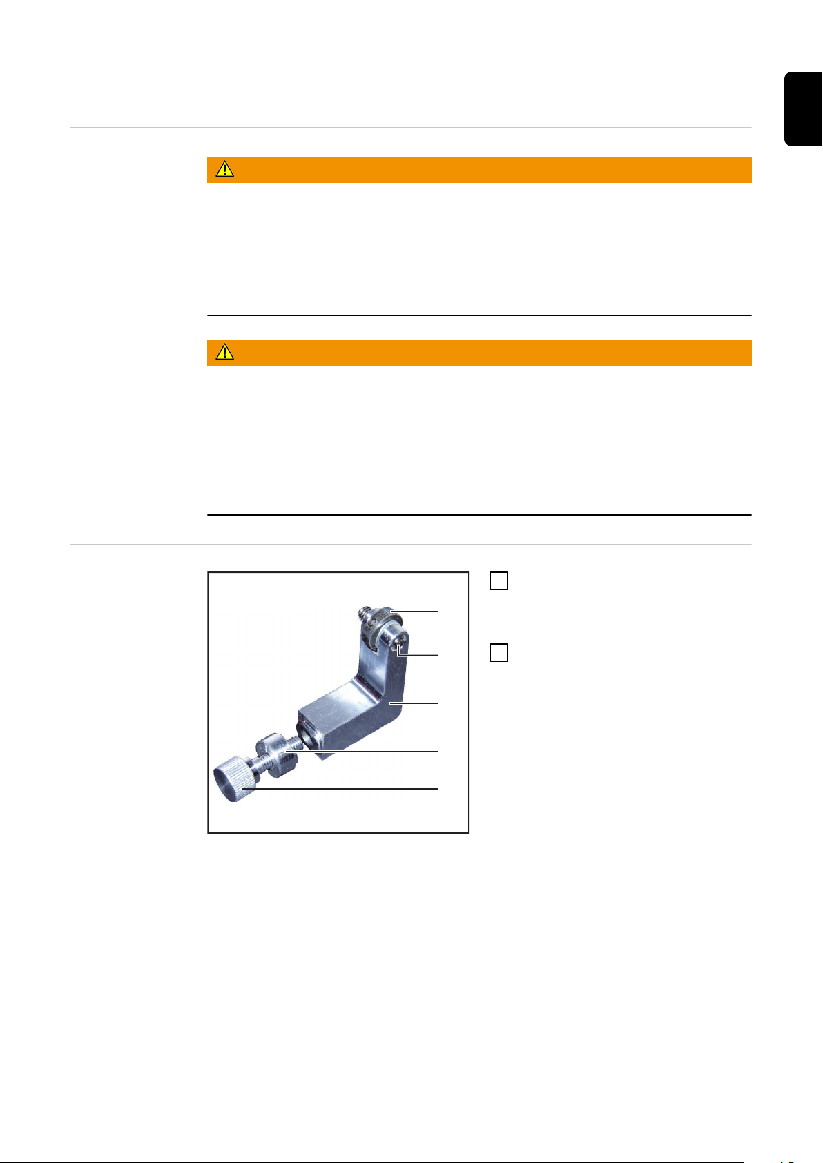
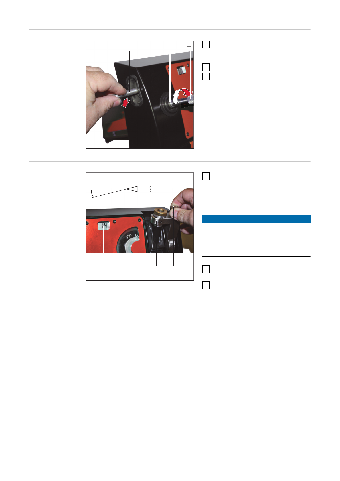
Längenanschlag
montieren
Rändelmutter (1) drehen bis die
1
Anschlagschraube (2) bündig mit
der breiten Seite des Anschlagwinkel (3) abschließt
Die Klemmschraube (5) und die
2
Hülse (4) vom Anschlagwinkel (3)
abnehmen
11
Page 12

3
4
(3)
(5)
Anschlagwinkel (3) von hinten in
1
2
(1)
(2) (3)
3
das Ger
Anschlagwinkel (3) mit der Hülse
4
(4) und der K
ät einsetzen
lemmschraube (5) fi-
xieren
HINWEIS!
Darauf achten, dass die Einstellkerbe
der Hülse (4) oben ist und sich der Anschl
agwinkel ganz rechts (in Nullposi-
tion) befindet.
Handgriff für
T
renneinrich-
tung montieren
Elektrodenhalter
zusammenbauen
Den Handgriff für die Trenneinrich-
1
tung an der link
en Seite des
Gerätes einschrauben und festziehen
Die Spannhülse (2) mit dem Durch-
1
messer der zu schl
eifenden Elektrode in das Unterteil (3) des Elektrodenhalters einsetzen
Das Oberteil (1) des Elektrodenhal-
2
t
ers in das Unterteil (3) einschrau-
ben, aber nicht festziehen
12
Page 13

Schleifflüssig-
(2)(1)
(1)
keit einfüllen
Kontrollieren ob der Keil zum Fi-
1
xieren des Tanks gut sitzt
Schleifflüssigkeit durch die
2
Führungsbuchse für die Schleifeinrichtung einfüllen
Der Flüssigkeitsstand muss sich
3
zwischen der Min. Marke (1) und
der Max. Marke (2) befinden
HINWEIS!
Die Schleifflüssigkeit wird zum Teil
von der Scheibe aufgenommen.
Vor jeder Inbetriebnahme den
▶
Flüssigkeitsstand überprüfen und
falls erforderlich korrigieren.
DE
Führungsbuchse
einstellen
Führungsbuchse (1) bis zum An-
1
schlag nach unten drehen
13
Page 14

Inbetriebnahme
Sicherheit
Gefahr durch Fehlbedienung und fehlerhaft durchgeführte Arbeiten.
Schwere Personen- und Sachschäden können die Folge sein.
▶
▶
▶
Aufstellbestimmungen
Netzanschluss An der Gehäuseunterseite befindet sich das Leistungsschild mit Angabe der
-
-
-
-
zulässigen Netzspannung und Netzfrequenz. Nur für diese Werte ist das Gerät
ausgelegt.
Die Absicherung der Netzzuleitung ist entsprechend der Geräteleistung festzulegen. Die Geräteleistung ist am Leistungsschild und im Kapitel „Technische Daten“
zu finden.
Der Betrieb des Gerätes ist nur mit werkseitig montiertem Netzkabel und Netzstecker zulässig.
WARNUNG!
Alle in diesem Dokument beschriebenen Arbeiten und Funktionen dürfen
nur von technisch geschultem Fachpersonal ausgeführt werden.
Dieses Dokument vollständig lesen und verstehen.
Sämtliche Sicherheitsvorschriften und Benutzerdokumentationen dieses
Gerätes und aller Systemkomponenten lesen und verstehen.
Das Gerät auf einer stabilen und ebenen Oberfläche aufstellen
Das Gerät so aufstellen, dass die Kühlluft ungehindert durch die Luftschlitze
an der Unterseite und der Rückseite strömen kann
Für ausreichende Beleuchtung am Arbeitsplatz sorgen
Das Gerät nicht im Freien betreiben
Inbetriebnahme
HINWEIS!
Nicht ausreichend dimensionierte Elektroinstallation kann zu Sachschäden
führen.
Die Netzzuleitung sowie deren Absicherung entsprechend der vorhandenen
▶
Stromversorgung auslegen.
Es gelten die Technischen Daten auf dem Leistungsschild.
Den Hauptschalter in Stellung - O - schalten
1
Netzstecker einstecken
2
Den Elektrodenhalter in die Führungsbuchse der Schleifeinrichtung stecken
3
um ein Herausspritzen von Schleifflüssigkeit zu vermeiden
Das Gerät für ca. 5 Sekunden einschalten
4
Die Schleifflüssigkeit verteilt sich im Gerät
Flüssigkeitsstand überprüfen und falls erforderlich Schleifflüssigkeit
5
nachfüllen
14
Page 15
Elektrode schleifen
1
2
2
(1) (2) (3)
6
4
(4)
(5)
DE
Allgemeines
Elektrode vorbereiten
HINWEIS!
Um eine Elektrode schleifen zu können, muss sie eine Mindestlänge von 30 mm
besitzen.
Die Verarbeitung kürzerer Elektroden ist im Abschnitt „Herstellen einer Elektrode kürzer als 25 mm“ beschrieben.
Die Elektrode (1) von vorne in die
1
Spannhülse des Elektrodenhalters
stecken
Die Elektrode muss vorne noch
-
ca. 25 mm herausragen
Vorderteil (2) und Hinterteil (3) des
2
Elektrodenhalters wie abgebildet
verdrehen und die Elektrode nur
leicht spannen
Die Elektrode darf nicht mehr von
selbst verrutschen, muss aber
noch von Hand verschiebbar sein
Klemmschraube (5) öffnen
3
Längenanschlag in Nullposition
4
stellen
Klemmschraube (5) festziehen
5
Den Elektrodenhalter bis auf An-
6
schlag in die Führungsbuchse (4)
des Längenanschlages stecken
Dadurch wird die Länge der
-
Elektrode exakt eingestellt
Elektrodenhalter-Hinterteil (3)
7
festschrauben
Elektrode wird im Elektroden-
-
halter eingespannt
15
Page 16
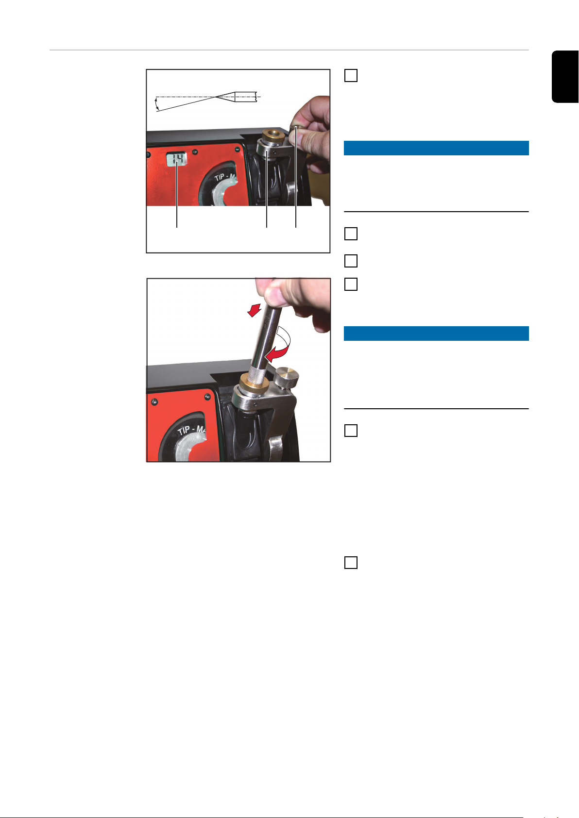
Elektrode schlei-
(3) (1)(2)
14°
5
4
fen
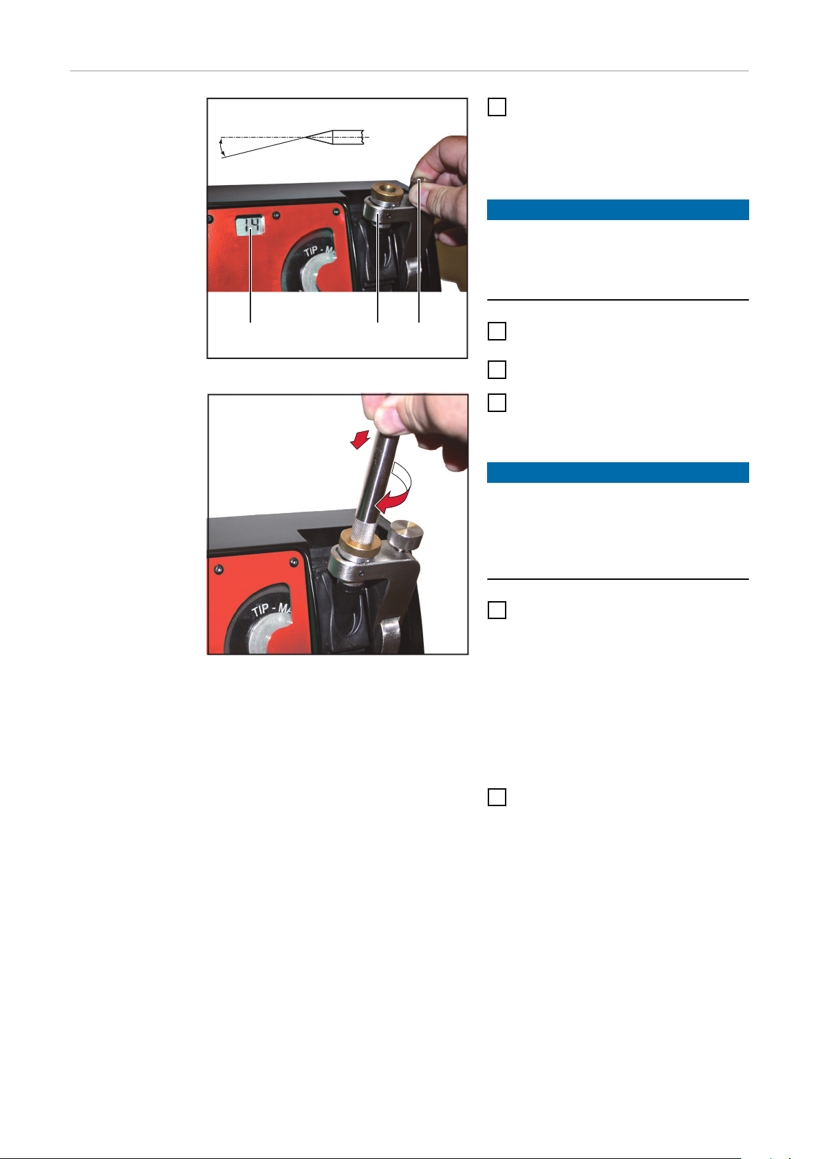
Die Rändelschraube (1) öffnen und
1
die Winkelverstellung (2) auf den
gewünschten Winkel einstellen
Den eingestellten Winkel an
-
der Digitalanzeige (3) ablesen
HINWEIS!
Der eingestellte Winkel entspricht
dem halben Spitzenwinkel.
Im dargestellten Beispiel würde ein
Spitzenwinkel von 28° entstehen.
Die Rändelschraube (1) wieder
2
festziehen
Gerät einschalten
3
Den Elektrodenhalter in die
4
Führungsbuchse der Schleifeinrichtung einführen
HINWEIS!
Während dem Schleifvorgang keinen
Druck auf die Elektrode ausüben.
Das Gewicht des Elektrodenhalters
reicht aus, um den Schleifvorgang
durchzuführen.
Sobald die Elektrode Kontakt mit
5
der Schleifscheibe aufnimmt, den
Elektrodenhalter langsam drehen
Der Schleifvorgang ist abgeschlossen wenn
der Konus des Elektrodenhal-
-
ters den Konus der Führungsbuchse berührt und
kein Schleifgeräusch mehr zu
-
hören ist
Elektrodenhalter entnehmen und
6
Gerät ausschalten
16
Page 17
Elektrodenspitze abtrennen
(1)
(2)
1
2
2
(1) (2) (3)
Allgemeines Zum Abtrennen einer Elektrode muss die richtige Elektrodenführung an der
Trenneinrichtung montiert sein.
Werkseitig ist die Elektrodenführung für Elektrodendurchmesser von 2,4 mm bis
3,2 mm montiert.
DE
Elektrodenführung
wechseln
Vorbereitung
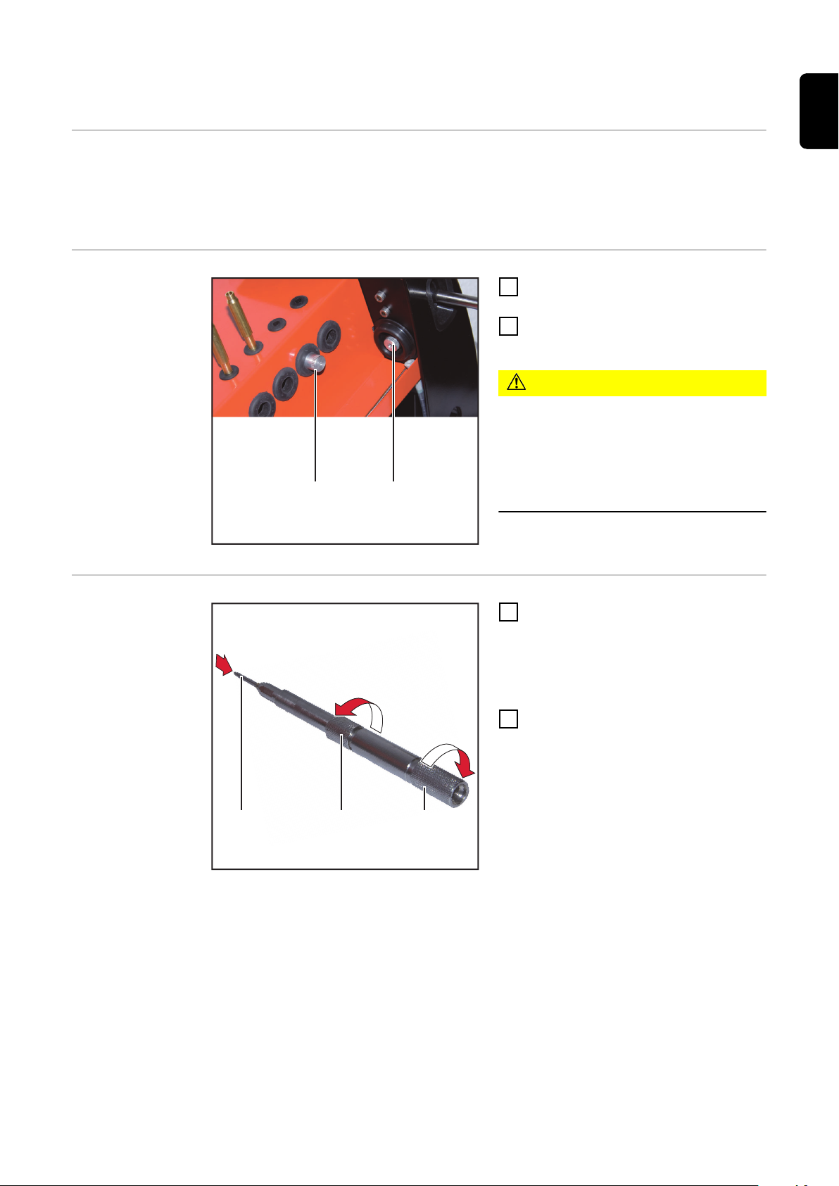
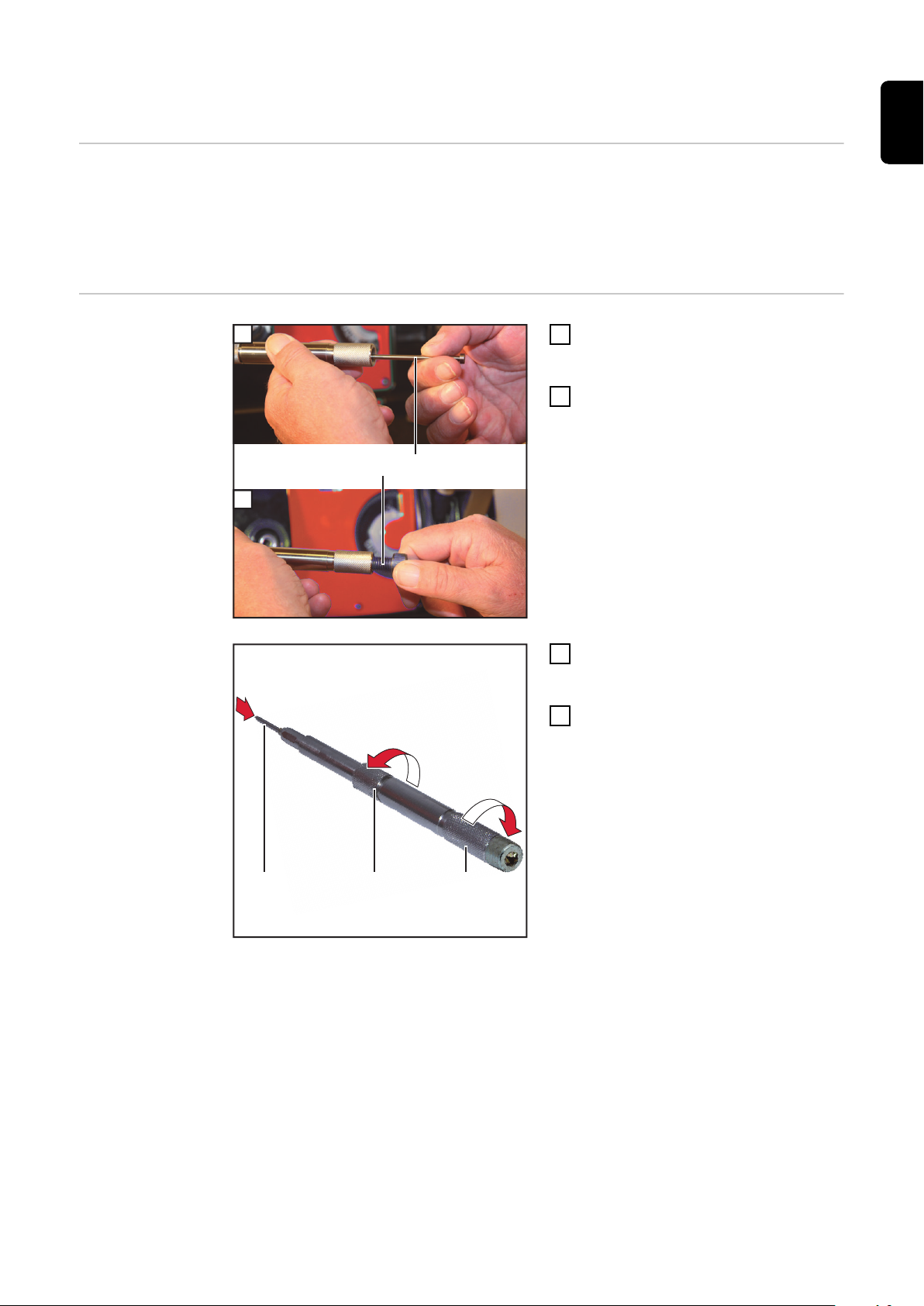
Bei Bedarf die eingebaute Elektro-
1
denführung (1) herausdrehen
Die benötigte Elektrodenführung
2
(2) einschrauben
VORSICHT!
Gefahr durch zu große Elektrodenführung beim Abtrennvorgang.
Eine Beschädigung der Elektrode kann
die Folge sein.
Abtrennvorgang mit der korrekten
▶
Elektrodenführung durchführen.
Die Elektrode (1) von vorne in die
1
Spannhülse des Elektrodenhalters
stecken
Die Elektrode muss vorne noch
ca. 25 mm herausragen
Vorderteil (2) und Hinterteil (3) des
2
Elektrodenhalters wie abgebildet
verdrehen und die Elektrode nur
leicht spannen
Die Elektrode darf nicht mehr von
selbst verrutschen, muss aber
noch von Hand verschiebbar sein
17
Page 18
(A)
Längenanschlag auf die Spit-
3
3
(3)
(1) (2)
3
zenlänge (A) einstellen
Den Elektrodenhalter bis auf An-
4
schlag in die Führungsbuchse des
Längenanschlages stecken
Dadurch wird die Länge der Elektrode exakt eingestellt
Elektrodenhalter-Hinterteil (3)
5
festschrauben
Elektrode wird im Elektroden-
-
halter eingespannt
Elektrodenspitze
abtrennen
Den Elektrodenhalter (3) bis zum
1
Anschlag in die Führungsbuchse
(2) der Trenneinrichtung einführen
Gerät einschalten
2
Elektrodenhalter (3) drehen und
3
Handgriff (1) langsam nach unten
drücken
Elektrode wird abgetrennt
-
Gerät ausschalten
4
HINWEIS!
Die Elektrode kann nun sofort geschliffen werden.
Die Einstellung der Länge ist nicht mehr erforderlich.
18
Page 19
Elektrode mit definierter Länge herstellen
1
2
(2)(1)
3
4
4
(3) (4) (5)
Allgemeines Mit Hilfe der beiliegenden Anschlagstifte können Elektroden mit einer definier-
ten Länge von 92 mm oder 30 mm hergestellt werden.
Dabei wird die im Elektrodenhalter eingespannte Elektrode mit der Trenneinrichtung auf die definierte Länge abgetrennt und kann dann sofort geschliffen werden.
DE
Vorbereitung
Den Anschlagstift (2) für die
1
gewünschte Länge in das Hinterteil
(5) des Elektrodenhalters einlegen
Den Anschlagstift mit der Schrau-
2
be M10 (1) fixieren
Die Elektrode (3) bis zum Anschlag
3
von vorne in den Elektrodenhalter
schieben
Vorderteil (4) und Hinterteil (5) des
4
Elektrodenhalters wie abgebildet
verdrehen und die Elektrode fest
einspannen
19
Page 20
Elektrode mit
3
3
(3)
(1) (2)
(3) (1)(2)
14°
definier
ter
Länge herstellen
Den Elektrodenhalter (3) bis zum
1
Anschlag in die F
ührungsbuchse
(2) der Trenneinrichtung einführen
Gerät einschalten
2
Elektrodenhalter (3) drehen und
3
Handgrif
f (1) langsam nach unten
drücken
Elektrode wird abgetrennt
-
Elektrode schleif
en
Die Rändelschraube (1) öffnen und
1
die Wink
elverstellung (2) auf den
gewünschten Winkel einstellen
Den eingestellten Winkel an
-
der Digitalanzeige (3) ablesen
HINWEIS!
Der eingestellte Winkel entspricht
dem halben Spitz
enwinkel.
Im dargestellten Beispiel würde ein
Spitzenwinkel von 28° entstehen.
Die Rändelschraube (1) wieder
2
estziehen
f
Gerät einschalten
3
20
Page 21

5
4
Den Elektrodenhalter in die
4
Führungsbuchse der Schleifeinrichtung einführen
HINWEIS!
Während dem Schleifvorgang keinen
Druck auf die Elektrode ausüben.
Das Gewicht des Elektrodenhalters
reicht aus, um den Schleifvorgang
durchzuführen.
Sobald die Elektrode Kontakt mit
5
der Schleifscheibe aufnimmt, den
Elektrodenhalter langsam drehen
Der Schleifvorgang ist abgeschlossen wenn
der Konus des Elektrodenhal-
-
ters den Konus der Führungsbuchse berührt und
kein Schleifgeräusch mehr zu
-
hören ist
Elektrodenhalter entnehmen und
6
Gerät ausschalten
DE
21
Page 22

Herstellen einer Elektrode kürzer als 25 mm
1
2
2
(1) (2) (3)
6
4
(4)
(5)
Allgemeines Bei der Herstellung einer Elektrode kürzer als 25 mm wird die Elektrode zuerst
geschliffen, so wie im Abschnitt „Elektrode schleifen“ beschrieben.
Die fertig geschliffene Elektrode wird dann auf die gewünschte Länge abgetrennt.
HINWEIS!
Um eine sehr kurze Elektrode herstellen zu können, muss das Ausgangsmaterial
min. 30 mm länger sein als die gewünschte Endlänge.
z.B: gewünschte Endlänge 10 mm = Ausgangslänge min. 40 mm
Elektrode vorbereiten
Die Elektrode (1) von vorne in die
1
Spannhülse des Elektrodenhalters
stecken
Die Elektrode muss vorne noch
-
ca. 25 mm herausragen
Vorderteil (2) und Hinterteil (3) des
2
Elektrodenhalters wie abgebildet
verdrehen und die Elektrode nur
leicht spannen
Die Elektrode darf nicht mehr von
selbst verrutschen, muss aber
noch von Hand verschiebbar sein
Klemmschraube (5) öffnen
3
Längenanschlag in Nullposition
4
stellen
Klemmschraube (5) festziehen
5
Den Elektrodenhalter bis auf An-
6
schlag in die Führungsbuchse (4)
des Längenanschlages stecken
Dadurch wird die Länge der
-
Elektrode exakt eingestellt
Elektrodenhalter-Hinterteil (3)
7
festschrauben
Elektrode wird im Elektroden-
-
halter eingespannt
22
Page 23
Elektrode schlei-
(3) (1)(2)
14°
5
4
fen
Die Rändelschraube (1) öffnen und
1
die Winkelverstellung (2) auf den
gewünschten Winkel einstellen
Den eingestellten Winkel an
-
der Digitalanzeige (3) ablesen
HINWEIS!
Der eingestellte Winkel entspricht
dem halben Spitzenwinkel.
Im dargestellten Beispiel würde ein
Spitzenwinkel von 28° entstehen.
Die Rändelschraube (1) wieder
2
festziehen
Gerät einschalten
3
Den Elektrodenhalter in die
4
Führungsbuchse der Schleifeinrichtung einführen
HINWEIS!
Während dem Schleifvorgang keinen
Druck auf die Elektrode ausüben.
Das Gewicht des Elektrodenhalters
reicht aus, um den Schleifvorgang
durchzuführen.
DE
Sobald die Elektrode Kontakt mit
5
der Schleifscheibe aufnimmt, den
Elektrodenhalter langsam drehen
Der Schleifvorgang ist abgeschlossen wenn
der Konus des Elektrodenhal-
-
ters den Konus der Führungsbuchse berührt und
kein Schleifgeräusch mehr zu
-
hören ist
Elektrodenhalter entnehmen und
6
Gerät ausschalten
23
Page 24
Herstellen einer
5
2
(1)
(2)
7
7
(5)
(3) (4)
ektrode kürzer
El
als 25 mm
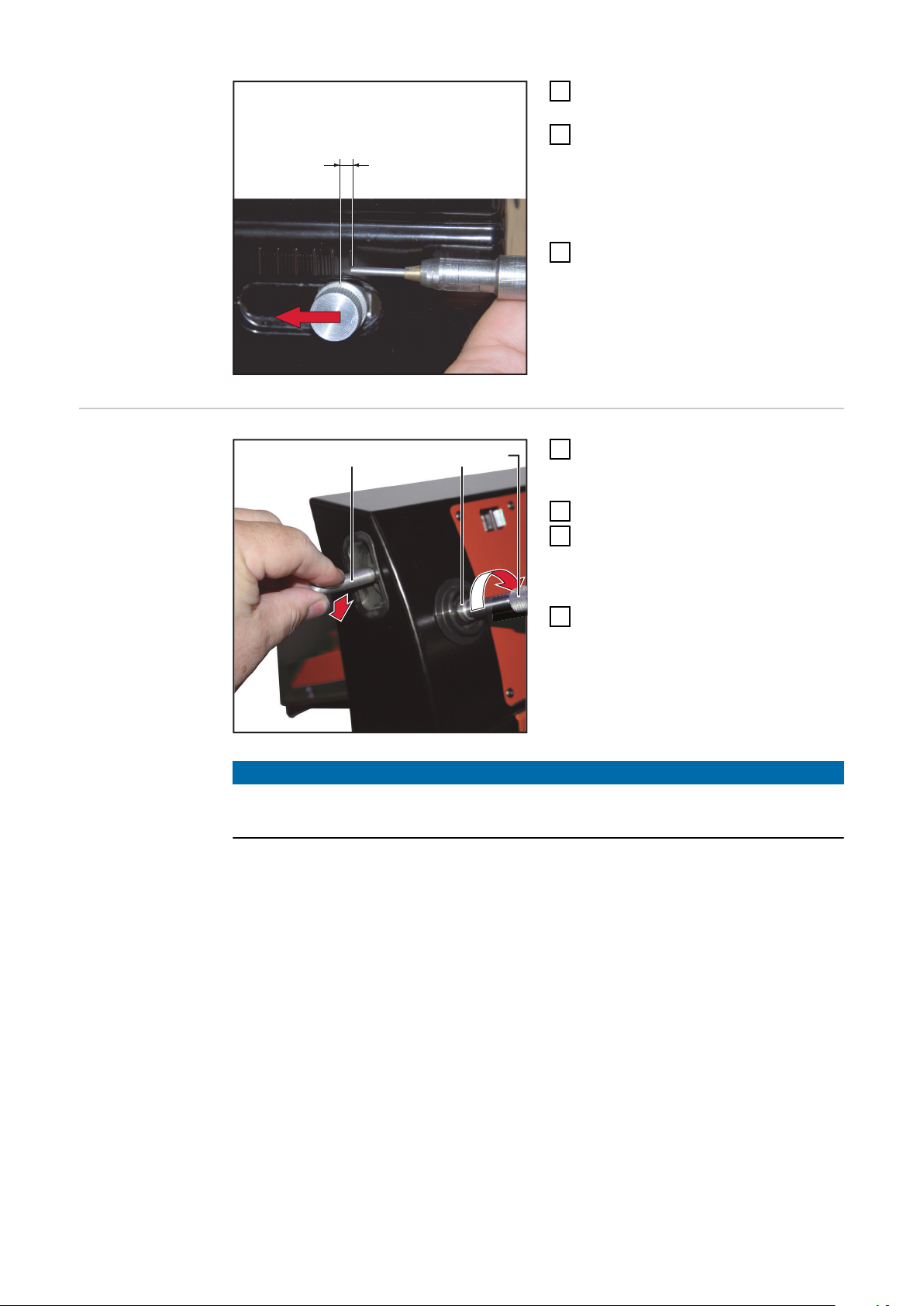
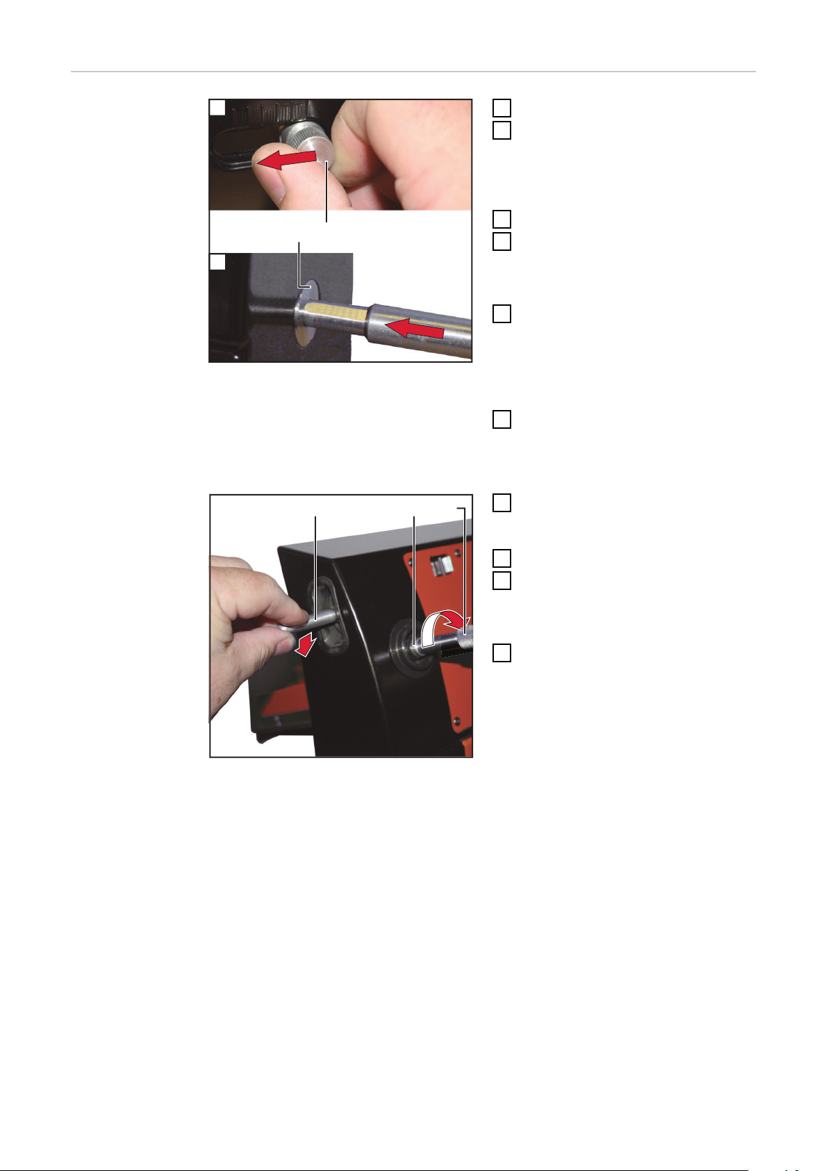
Klemmschraube (2) öffnen
1
Den Längenanschlag auf die
2
gewünsch
te Endlänge der Elektrode + 3 mm einstellen
(z.B. Endlänge 10 mm = Einstellwert 13 mm)
Klemmschraube (2) festziehen
3
Den Elektrodenhalter ein wenig
4
fnen und die Elektrode mehr als
öf
die eingestellte Länge herausziehen
Den Elektrodenhalter bis auf An-
5
schlag in die F
ührungsbuchse (1)
des Längenanschlages stecken
Dadurch wird die Länge der Elektrode exakt eingestellt
Elektrodenhalter-Hinterteil fest-
6
auben
schr
Elektrode wird im Elektroden-
-
halter eingespannt
Den Elektrodenhalter (5) bis zum
5
Anschlag in die F
ührungsbuchse
(4) der Trenneinrichtung einführen
Gerät einschalten
6
Elektrodenhalter (5) drehen und
7
Handgrif
f (3) langsam nach unten
drücken
Elektrode wird abgetrennt
-
Gerät ausschalten
8
24
Page 25

Herstellen einer abgestumpften Elektrodenspitze
1
2
2
(1) (2) (3)
(3) (1)(2)
1
Allgemeines Das Abstumpften einer geschliffenen Elektrodenspitze kommt hauptsächlich bei
automatisierten Schweißprozessen zur Anwendung.
Durch das Abstumpfen wird die Standzeit der Elektrode erhöht.
DE
Vorbereitung
HINWEIS!
Ein korrektes Abstumpfen der Elektrodenspitze ist nur möglich wenn die Elektrode zuvor geschliffen wurde.
Siehe Abschnitt „Elektrode schleifen“.
Die geschliffene Elektrode (1) von
1
vorne in die Spannhülse des Elektrodenhalters stecken
Das Ende mit der geschliffenen
Spitze soll vorne noch ca. 25 mm
herausragen
Vorderteil (2) und Hinterteil (3) des
2
Elektrodenhalters wie abgebildet
verdrehen und die Elektrode nur
leicht spannen
Die Elektrode darf nicht mehr von
selbst verrutschen, muss aber
noch von Hand verschiebbar sein
Herstellen einer
abgestumpften
Elektrodenspitze
Die Rändelschraube (1) öffnen und
1
die Winkelverstellung (2) auf 90°
einstellen
Der eingestellte Winkel kann an
der Digitalanzeige (3) abgelesen
werden
Die Rändelschraube (1) wieder
2
festziehen
25
Page 26
(5)(4)
4
5
3
5
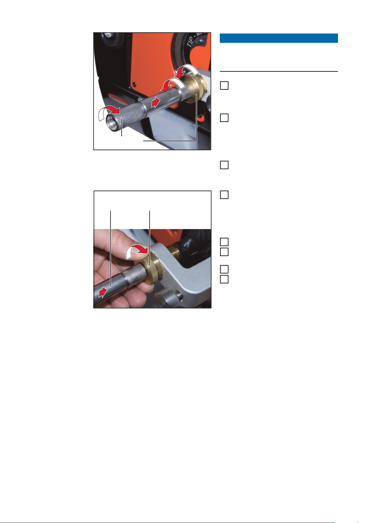
HINWEIS!
(4) (5)
8
6
Die Führungsbuchse (5) der Schleifeinrichtung rastet beim Verdrehen in
0,1 mm Schritten ein.
Die Führungsbuchse (5) ca. 2 -
3
3 mm gegen den Uhrzeigersinn
herausdrehen (ca. 20 - 30 Rasterschritte)
Den Elektrodenhalter (4) bis zum
4
Anschlag in die Führungsbuchse
der Schleifeinrichtung einführen
Dadurch wird die Länge der Elektrode exakt eingestellt
Vorder- und Hinterteil des Elektro-
5
denhalters (4) verdrehen
Elektrode wird gespannt
-
Führungsbuchse (5) im Uhrzeiger-
6
sinn drehen um die gewünschte
Abflachung der Elektrodenspitze
einzustellen
(z.B. 5 Rasterschritte = 0,5 mm
Abflachung)
Gerät einschalten
7
Elektrodenhalter bis zum Anschlag
8
einführen
Elektrodenhalter entnehmen
9
Gerät ausschalten
10
26
Page 27

Fehlerdiagnose
DE
Fehler an der
Elektrode
Elektrode wird nicht spitz geschliffen
Ursache:
Behebung:
Ursache:
Behebung:
Ursache:
Behebung:
Elektrode wird nicht spitz geschliffen
Scheibenverschleiß-Ausgleich wurde bereits vorgenommen
Ursache:
Behebung:
Elektrode wird nicht spitz geschliffen
Scheibenverschleiß-Ausgleich wurde bereits vorgenommen; alle Schleifspuren
wurden benutzt
Ursache:
Behebung:
Führungsbuchse nicht in Nullposition
Führungsbuchse der Schleifeinrichtung ganz hineindrehen
Längenanschlag steht etwas rechts der Nullposition
Längenanschlag in Nullposition stellen
Scheibenverschleiß zu groß
Scheibenverschleiß ausgleichen durch Feinjustierung des Längenan-
schlages
Scheibenverschleiß hat Maximalwert erreicht
Schleifspur wechseln
Schleifscheibe ist verschlissen
Schleifscheibe wechseln
Elektrode wird zu viel geschliffen
Der Überstand der Elektrode im Elektrodenhalter ist zu lange, daher wird mehr
Material als notwendig von der Elektrode weggeschliffen
Ursache:
Behebung:
Ursache:
Behebung:
Elektrode läuft beim Schleifen blau an
Die Elektrode wird während dem Schleifvorgang zu heiß
Ursache:
Behebung:
Ursache:
Behebung:
Längenanschlag steht links der Nullposition
Längenanschlag in Nullposition stellen
Der Ausgleich des Scheibenverschleißes wurde nach einem Schleifscheiben-Wechsel nicht zurückgestellt
Feinjustierung des Längenanschlages in Nullposition zurückstellen
Zu hoher Schleifdruck
Während dem Schleifvorgang keinen Druck auf die Elektrode
ausüben. Das Gewicht des Elektrodenhalters reicht aus, um den
Schleifvorgang durchzuführen.
Zu wenig Schleifflüssigkeit im Gerät
Schleifflüssigkeit nachfüllen; siehe Abschnitt „Schleifflüssigkeit
einfüllen“
27
Page 28

Fehler am Gerät
Trenneinrichtung schneidet nicht
Die Elektrode wird nicht oder nur zum Teil durchgeschnitten
Ursache:
Behebung:
Ursache:
Behebung:
Ursache:
Behebung:
Schleifflüssigkeit läuft aus
Ursache:
Behebung:
Ursache:
Behebung:
Ursache:
Behebung:
Elektrode wurde beim Schneiden zu wenig gedreht
Elektrode am Ende des Schneidvorganges noch mehrmals drehen
Trennscheibe ist verschlissen
Trennscheibe wechseln
Der Antriebsriemen ist defekt
Servicedienst verständigen
Ablass-Schlauch nicht verschlossen
Ablass-Schlauch zum Entleeren des Tanks verschließen und in der
Sammeltasse an der linken Seite des Gerätes fixieren
Dichtung zwischen Sichtfenster und Gehäuse ist undicht
Schleifflüssigkeit ablassen; Gehäusedeckel entfernen; Dichtung rei-
nigen oder austauschen
Tankdichtung ist undicht
Schleifflüssigkeit ablassen; Tank entnehmen; Dichtung reinigen oder
austauschen
Digitalanzeige zeigt nichts an
Ursache:
Behebung:
Ursache:
Behebung:
Die Batterie der Digitalanzeige ist leer
Batterie der Digitalanzeige wechseln
Die Digitalanzeige ist defekt
Servicedienst verständigen
28
Page 29

Fehlerbehebung
DE
Sicherheit
WARNUNG!
Gefahr durch Fehlbedienung.
Schwerwiegende Personen- und Sachschäden können die Folge sein.
Vor dem Anwenden der beschriebenen Funktionen diese Bedienungsanlei-
▶
tung lesen und verstehen.
Vor dem Anwenden der beschriebenen Funktionen die Sicherheitsda-
▶
tenblätter der eingesetzten Materialien, insbesondere der zu schleifenden
Elektroden lesen und verstehen.
WARNUNG!
Gefahr durch elektrischen Strom.
Schwere Personen- und Sachschäden können die Folge sein.
Vor Beginn der Arbeiten alle beteiligten Geräte und Komponenten ausschal-
▶
ten und von Stromnetz trennen.
Alle beteiligten Geräte und Komponenten gegen Wiedereinschalten sichern.
▶
Nach dem Öffnen des Gerätes mit Hilfe eines geeigneten Messgerätes si-
▶
cherstellen, dass elektrisch geladene Bauteile (beispielsweise Kondensatoren) entladen sind.
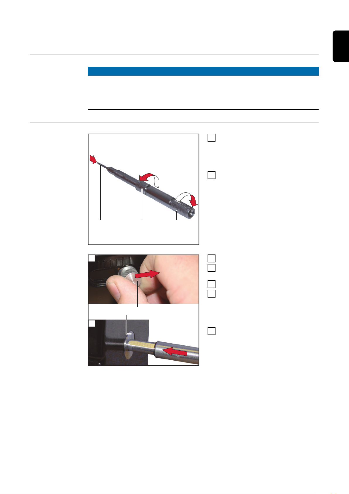
Fehlerbehebeung Übersicht
Benötigte Werkzeuge und Hilfsmittel
Scheibenverschleiß ausgleichen
„Fehlerbehebung“ setzt sich aus folgenden Abschnitten zusammen
Benötigte Werkzeuge und Hilfsmittel
-
Scheibenverschleiß ausgleichen
-
Schleifspur wechseln
-
Schleifflüssigkeit ablassen
-
Deckplatte entfernen
-
Schleifscheibe wechseln
-
Trennscheibe wechseln
-
Deckplatte montieren
-
Schleifflüssigkeit einfüllen
-
Batterie der Digitalanzeige wechseln
-
Folgende Werkzeuge und Hilfsmittel werden benötigt:
Innensechskant-Schlüssel 2,5 mm
-
Innensechskant-Schlüssel 5 mm (für Schleifscheibe)
-
Innensechskant-Schlüssel 6 mm (für Trennscheibe)
-
Torx-Schraubendreher TX25
-
Auffangbehälter für Schleifflüssigkeit (Fassungsvermögen min. 500 ml)
-
Der Ausgleich des Scheibenverschleißes erfolgt durch eine Feinjustierung des
Längenanschlages.
29
Page 30
(1)
(2)
Einstellschraube (1) eine halbe
(1)
(2) (3)
(3)(2)
(1)
2
1
Umdrehung in die angegebene
Richtung drehen um den Anschlagstift (2) nach hinten zu bewegen
Einen Schleifvorgang durchführen
2
um das Ergebnis zu testen
Schritt 1 und 2 so oft durchführen
3
bis das Ergebnis zufriedenstellend
ist
Schleifspur
wechseln
Schleifflüssigkeit ablassen
Innensechskant-Schraube (1) mit
1
Innensechskant-Schlüssel 2,5 mm
lösen
Die Führungsbuchse (2) um eine
2
Kerbe (3) verstellen.
Innensechskant-Schraube (1) wie-
3
der anziehen
Anzugsdrehmoment = 0,5 Nm
Den Ablass-Schlauch (2) aus der
1
Sammeltasse an der linken Seite
des Gerätes entnehmen
HINWEIS!
Schlauch höher als die Füllstands-Anzeige halten.
Sonst läuft sofort Schleifflüssigkeit
aus wenn der Verschluss (1) geöffnet
wird.
Verschluss (1) öffnen
2
Den Schlauch in ein Auffanggefäß
3
mit min. 500 ml Fassungsvermögen stecken
30
Page 31

Das Auffanggefäß mit dem
(4)
(5)(3)
4
Schlauch tief
er halten als die
Oberkante des Tanks (3) für die
Schleifflüssigkeit.
Schleifflüssigkeit auslauf
5
Verschluss (1) wieder verschließen
6
wenn k
eine Schleifflüssigkeit mehr
en lassen
aus dem Schlauch läuft
HINWEIS!
DE
Es befindet sich noch
Schleifflüssig-
keit im Tank.
Über den Ablass-Schlauch wurde nur
die Schleifflüssigkeit aus dem
Gehäuse des Gerätes entfernt
Den Keil (4) zum Fixieren des Tanks
7
nach vorne herausziehen
Den Tank (3) nach unten aus dem
8
Gehäuse ziehen
Den Tank vollständig entleeren und
9
einigen
r
Tankdichtung (5) reinigen und
-
kontrollieren
Tank wieder einsetzen und mit Keil
10
en
fixier
Der Keil muss hörbar einrasten
-
Den Ablass-Schlauch wieder in die
11
Sammel
tasse stecken
31
Page 32

Deckplatte ent-
(1) (2) (3) (4) (5) (6)
(2)
(3)
(1)
(4)
ernen
f
HINWEIS!
Vor dem Entfernen der Deckplatte sicher
stellen, dass sich keine
Schleifflüssigkeit mehr im Gehäuse
befindet.
Die Innensechskant-Schrauben
1
(1) ‑ (6) der Deckpla
tte mit Innensechskant-Schlüssel 2,5 mm entfernen
Deckplatte und Sichtfenster ab-
2
nehmen
Schleifscheibe
w
echseln
Die Befestigungsschraube (2) der
1
Schl
eifscheibe mit einem Innensechskant-Schlüssel 5 mm entfernen
Zum Gegenhalten den Innensechskant-Schlüssel 2,5 mm in ein
Loch (3) der Deckscheibe (1) stecken
Deckscheibe (1) entfernen und
2
Schl
eifscheibe von der Antriebswelle abnehmen
Wenn sich die Schleifscheibe (4)
3
sch
wer von der Antriebswelle löst,
mit dem Innensechskant-Schlüssel
5 mm die Schleifscheibe etwas
nach vorne ziehen
Die Schleifscheibe etwas verdre-
4
hen und mit dem Innensechsk
Schlüssel wieder nach vorne ziehen
Diesen Vorgang so lange wiederho-
5
l
en bis sich die Schleifscheibe von
der Antriebswelle abnehmen lässt
Neue Schleifscheibe einsetzen,
6
Deck
scheibe (1) aufsetzen und mit
der Befestigungsschraube (2) anschrauben
Anzugsdrehmoment = 5,0 Nm
ant-
32
Page 33

HINWEIS!
(1)(2)(3)
(1) (2) (3) (4) (5) (6)
Trennscheibe
w
echseln
Möglicherweise wurde am Längenanschlag ein Ausgleich für den Verschleiß der
Schl
eifscheibe vorgenommen.
Nach dem Einsetzen einer neuen Schleifscheibe ist diese Feinjustierung des
▶
Längenanschlages wieder auf den Installationszustand zurückzusetzen. (siehe Abschnitt „Längenanschlag montieren“)
Die Befestigungsschraube (2) der
1
Schl
eifscheibe mit einem Innensechskant-Schlüssel 6 mm entfernen
Zum Gegenhalten den Innensechskant-Schlüssel 2,5 mm in ein
Loch (3) der Deckscheibe (1) stecken
Deckscheibe (1) entfernen und
2
Schl
eifscheibe von der Antriebswelle abnehmen
Neue Trennscheibe einsetzen,
3
Deck
scheibe (1) aufsetzen und mit
der Befestigungsschraube (2) anschrauben
DE
Deckplatte montier
en
Anzugsdrehmoment = 5,0 Nm
Dichtung zwischen Sichtfenster
1
und Gehäuse r
Sichtfenster und Deckplatte auf-
2
se
tzen
Die Innensechskant-Schrauben
3
(1) ‑ (6) der Deckpla
einigen
tte mit Innensechskant-Schlüssel 2,5 mm anziehen
Anzugsdrehmoment = 0,5 Nm
33
Page 34

Schleifflüssig-
(2)(1)
keit einfüllen
Kontrollieren ob der Keil zum Fi-
1
xieren des Tanks gut sitzt
Schleifflüssigkeit durch die
2
Führungsbuchse für die Schleifeinrichtung einfüllen
Der Flüssigkeitsstand muss sich
3
zwischen der Min. Marke (1) und
der Max. Marke (2) befinden
HINWEIS!
Die Schleifflüssigkeit wird zum Teil
von der Scheibe aufgenommen.
Vor jeder Inbetriebnahme den
▶
Flüssigkeitsstand überprüfen und
falls erforderlich korrigieren.
34
Page 35

Batterie der Di-
(1) (2)
(3)
(4)
(5)
gitalanzeige
wechseln
Für diese Tätigkeit wird eine Batterie der Type CR2032 oder CR2450 benötigt.
WARNUNG!
Gefahr durch falsche Einstellung von Riemenspannung oder Motordrehzahl.
P
ersonen oder Sachschäden können die Folge sein.
Keine Einstellarbeiten im Geräteinneren vornehmen. Nur die angegebenen
▶
Tätigkeiten durchführen.
DE
linke Gehäuseseite rechte Gehäuseseite
Schrauben TX25 (1) ‑ (4) link
1
rechts am Gehäuse entfernen
Gehäusedeckel ein Stück anheben
2
und Schutzl
stecken
Gehäusedeckel neben dem Gerät
3
abl
egen
eiter (5) vom Motor ab-
s und
35
Page 36

(6)
Die Batterie (6) seitlich entnehmen
4
und dur
ch eine neue Batterie der
Type CR2032 ersetzen.
Die neue Batterie so einsetzen,
dass der Minuspol aussen ist
Schutzleiter (5) anstecken und
5
Gehäusedeck
Gehäusedeckel mit Schrauben
6
TX25 (1) ‑ (4) link
el schließen
s und rechts am
Gehäuse anschrauben
Anzugsdrehmoment = 6,0 Nm
36
Page 37

Pflege, Wartung und Entsorgung
DE
Sicherheit
WARNUNG!
Gefahr durch Fehlbedienung.
Schwerwiegende Personen- und Sachschäden können die Folge sein.
Vor dem Anwenden der beschriebenen Funktionen diese Bedienungsanlei-
▶
tung lesen und verstehen.
Vor dem Anwenden der beschriebenen Funktionen die Sicherheitsda-
▶
tenblätter der eingesetzten Materialien, insbesondere der zu schleifenden
Elektroden lesen und verstehen.
WARNUNG!
Gefahr durch elektrischen Strom.
Schwere Personen- und Sachschäden können die Folge sein.
Vor Beginn der Arbeiten alle beteiligten Geräte und Komponenten ausschal-
▶
ten und von Stromnetz trennen.
Alle beteiligten Geräte und Komponenten gegen Wiedereinschalten sichern.
▶
Nach dem Öffnen des Gerätes mit Hilfe eines geeigneten Messgerätes si-
▶
cherstellen, dass elektrisch geladene Bauteile (beispielsweise Kondensatoren) entladen sind.
Allgemeines Das Gerät benötigt unter normalen Betriebsbedingungen nur ein Minimum an
Pflege und Wartung. Die Durchführung der nachstehend angeführten Tätigkeiten
ist jedoch unerlässlich, um es über Jahre hinweg einsatzbereit zu halten.
Vor jeder Inbetriebnahme
Alle 6 Monate oder bei jedem Schleifscheibenwechsel
Entsorgung Die Entsorgung nur gemäß den geltenden nationalen und regionalen Bestimmun-
Sichtkontrolle der beweglichen Teile
-
Kontrolle des Schleifflüssigkeits-Standes
-
Schleifflüssigkeit wechseln
-
Gerät gründlich reinigen
-
Zustand der Schleifscheibe kontrollieren
-
Zustand der Trennscheibe kontrollieren
-
gen durchführen.
37
Page 38

Technische Daten
TIG Grinder
Netzspannung 115 - 230 V
Netzfrequenz 50 / 60 Hz
Netzabsicherung 10 A
Motorleistung 800 W
Drehzahl 9500 U/min
Schleifgeschwindigkeit 60 m/s
Schleifscheiben-Durchmesser 100 mm
Trennscheiben-Durchmesser ca. 62 mm
Gewicht 12,8 kg
zulässige Elektroden-Durchmesser
in der Standardausführung: 1,6 mm / 2,4 mm / 3,2 mm
mit Zubehör: 1,0 mm / 2,0 mm / 4,0 mm / 4,8 mm
Batterie der Digitalanzeige
Spannung 3 V
Type
CR2032 oder CR2450
38
Page 39

Contents
Safety rules 41
Explanation of safety notices 41
General 41
Specific hazards 42
Proper use 42
Environmental conditions 42
Obligations of the operator 42
Qualified and trained technicians 43
Obligations of personnel 43
Maintenance and repair 43
Copyright 43
General 44
Device description 44
Scope of supply 44
Proper use 44
Control elements and connections 45
Control elements and connections 45
Installation 46
Safety 46
Fitting the length stop 46
Fitting the handle for the separator 47
Assembling the electrode holder 47
Adding grinding fluid 48
Adjusting the guide bushing 48
Start-up 49
Safety 49
Setup regulations 49
Mains connection 49
Starting up 49
Grinding the electrode 50
General 50
Preparing the electrode 50
Grinding the electrode 51
Cutting the electrode tip 52
General 52
Changing the electrode guide 52
Preparation 52
Cutting the electrode tip 53
Creating an electrode of a specific length 54
General 54
Preparation 54
Creating an electrode of a specific length 55
Grinding the electrode 55
Creating an electrode shorter than 25 mm 57
General 57
Preparing the electrode 57
Grinding the electrode 58
Creating an electrode shorter than 25 mm 59
Creating a blunt electrode tip 60
General 60
Preparation 60
Creating a blunt electrode tip 60
Fault diagnosis 62
Faults with the electrode 62
Faults with the device 63
Troubleshooting 64
Safety 64
Troubleshooting overview 64
Required tools and materials 64
Compensating for disc wear 64
EN
39
Page 40

Changing the grinding track 65
Draining the grinding fluid 65
Removing the cover plate 67
Changing the grinding disc 67
Changing the cutting wheel 68
Fitting the cover plate 68
Adding grinding fluid 69
Changing the digital display battery 70
Care, maintenance and disposal 72
Safety 72
General 72
Before each start-up 72
Every 6 months 72
Disposal 72
Technical data 73
TIG Grinder 73
40
Page 41

Safety rules
Explanation of
safety notices
DANGER!
Indicates immediate danger.
If not avoided, death or serious injury will result.
▶
WARNING!
Indicates a potentially hazardous situation.
If not avoided, death or serious injury may result.
▶
CAUTION!
Indicates a situation where damage or injury could occur.
If not avoided, minor injury and/or damage to property may result.
▶
NOTE!
Indicates a risk of flawed results and possible damage to the equipment.
EN
General The device has been manufactured in line with the state of the art and according
to recognised safety standards. If used incorrectly or misused, however, it can
cause:
Injury or death to the operator or a third party
-
Damage to the device and other material assets belonging to the operating
-
company
Inefficient operation of the device
-
All persons involved in commissioning, operating, maintaining and servicing the
device must:
Be suitably qualified
-
Have fully read and precisely followed these Operating Instructions
-
The Operating Instructions must always be at hand wherever the device is being
used. In addition to the Operating Instructions, all applicable local rules and regulations regarding accident prevention and environmental protection must also
be followed.
All safety and danger notices on the device:
Must be kept in a legible state
-
Must not be damaged
-
Must not be removed
-
Must not be covered, pasted or painted over
-
For the location of the safety and danger notices on the device, refer to the section headed "General" in the Operating Instructions for the device.
Before commissioning the device, rectify any faults that could compromise safety.
This is for your personal safety!
41
Page 42

Specific hazards Keep hands, hair, clothing and tools away from moving parts. For example:
Cogs
-
Rollers
-
Shafts
-
Hinges
-
Do not reach into rotating drive components.
Risk of crushing!
Do not put hands or any other parts of the body between the pressing parts.
Risk of cutting!
Wear safety gloves when handling sharp objects.
Covers and side panels may only be opened/removed while maintenance or repair
work is being carried out.
During operation
Ensure that all covers are closed and all side panels are fitted properly.
-
Keep all covers and side panels closed.
-
Proper use The device is to be used exclusively for its intended purpose.
Any use above and beyond this purpose is deemed improper. The manufacturer
shall not be held liable for any damage arising from such usage.
Environmental
conditions
Proper use also includes:
carefully reading and obeying all the instructions and all the safety and dan-
-
ger notices in the operating instructions
performing all stipulated inspection and servicing work
-
installation as specified in the operating instructions
-
Operation or storage of the device outside the stipulated area will be deemed as
not in accordance with the intended purpose. The manufacturer shall not be held
liable for any damage arising from such usage.
Ambient air temperature range:
During operation: + 5 °C to + 40 °C (41 °F to 104 °F)
-
During transport and storage: -15 °C to +55 °C (5 °F to 131 °F)
-
Relative humidity:
Up to 50% at 40 °C (104 °F)
-
Up to 80% at 20 °C (68 °F)
-
Keep ambient air free from dust, acids, corrosive gases and substances, etc.
Obligations of
the operator
42
The operator must only allow persons to work with the device who:
are familiar with the fundamental instructions regarding safety at work and
-
accident prevention and have been instructed in how to use the device
have read and understood these operating instructions, especially the sec-
-
tion "safety rules", and have confirmed as much with their signatures
are trained to produce the required results.
-
Page 43

Checks must be carried out at regular intervals to ensure that operators are
working in a safety-conscious manner.
Qualified and
trained technicians
Obligations of
personnel
Maintenance and
repair
Only qualified technicians, who have attended the appropriate Fronius training
course, are permitted to commission and operate the device. The information in
these operating instructions is only intended for these persons. Do not carry out
any procedures apart from those described in the operating instructions. This applies even if you are qualified to do so.
Before using the device, all persons instructed to do so undertake:
to observe the basic instructions regarding safety at work and accident pre-
-
vention
to read these operating instructions, especially the "Safety rules" section and
-
sign to confirm that they have understood them and will follow them.
Before leaving the workplace, ensure that people or property cannot come to any
harm in your absence.
Maintenance and repair work must only be carried out by authorised personnel.
Use only original spare and wearing parts (also applies to standard parts). It is
impossible to guarantee that bought-in parts are designed and manufactured to
meet the demands made on them, or that they satisfy safety requirements.
EN
Do not carry out any modifications, alterations, etc. to the device without the manufacturer's consent.
In addition to following the maintenance instructions, the device must be carefully monitored and any malfunctions must be rectified immediately. The manufacturer accepts no liability for consequential damage caused by inadequate
maintenance or incorrect operation of the device.
Copyright Copyright of these operating instructions remains with the manufacturer.
The text and illustrations are all technically correct at the time of printing. We
reserve the right to make changes. The contents of the operating instructions
shall not provide the basis for any claims whatsoever on the part of the purchaser. If you have any suggestions for improvement, or can point out any mistakes
that you have found in the instructions, we will be most grateful for your
comments.
43
Page 44

General
(6)
(1)
(7)
(8)
(9)
(10)
(11)
(2)
(3)
(4)
(5)
Device descripti-onThe device is used for sharpening and cutting the tungsten electrodes that are
used as the electrodes for TIG welding torches.
The angle of the tip is infinitely variable and is digitally displayed.
The separator allows electrodes of any minimum length to be created.
The flat side of the grinding disc is used to grind lengthwise along the electrode.
This produces optimum tip formation.
A choice of 3 grinding tracks is available to increase the service life of the grinding disc.
The electrode holder accurately positions the electrodes for grinding. This ensures precise and repeatable creation of the electrode tip.
There is a separate clamping sleeve for each electrode diameter; this ensures
that the electrode is securely located in the electrode holder.
The use of grinding fluid and a container avoids grinding dust emissions.
Scope of supply In addition to the base unit, the following elements are included in the scope of
supply:
(1) Handle for the separator
(2) M10 screw for the stop-bolt
(3) Back part of electrode holder
(4) Front part of electrode holder
(5) Length stop
(6) Clamping sleeve 3.2 mm
(7) Clamping sleeve 2.4 mm
(8) Clamping sleeve 1.6 mm
(9) Stop-bolt for 30 mm electrode
(10) Stop-bolt for 92 mm electrode
(11) Electrode guide 1.0 - 1.6 mm
Not shown:
250 ml grinding fluid
-
500 ml grinding fluid
-
Electrode guide 2.4 - 3.2 mm
-
(already fitted on the back of the
separator)
NOTE!
If required, ask the manufacturer for the material safety data sheets for the
grinding fluid.
Proper use The device is intended exclusively for grinding and/or cutting tungsten electro-
44
des. Any other form of usage is deemed "not in accordance with the intended
purpose". The manufacturer shall not be held liable for any damage arising from
such usage
Page 45

Control elements and connections
(1)
(9)
(2)
(3)
(4)
(5)
(6)
(7)
(10)
(11)
(13)
(12)
(8)
(15)
(16)
(16)
(17)
(18)
(14)
Control elements and connections
EN
(1) Electrode holder
(2) Digital display
(3) Handle for the separator
(4) Separator guide bushing
(5) Cover plate
(6) Tank for grinding fluid
(7) Key for fixing tank in place
(8) Knurled screw for securing
angle adjustment
(9) Grinding device guide bushing
(10) Angle adjustment
(11) Fill level inspection glass
(12) Length stop guide bushing
(13) Length stop
(14) Mains plug
(15) Main switch
(16) Tool storage
(17) Collecting cup
(18) Drain hose for emptying the
tank
45
Page 46

Installation
(1)
(2)
(3)
(4)
(5)
Safety
WARNING!
Danger from incorrect operation and work that is not carried out properly.
This can result in serious personal injury and damage to property.
All the work and functions described in this document must only be carried
▶
out by technically trained and qualified personnel.
Read and understand this document in full.
▶
Read and understand all safety rules and user documentation for this device
▶
and all system components.
WARNING!
Danger from electrical current.
This can result in serious personal injury and damage to property.
Before starting work, switch off all devices and components involved and dis-
▶
connect them from the grid.
Secure all devices and components involved so they cannot be switched back
▶
on.
After opening the device, use a suitable measuring instrument to check that
▶
electrically charged components (such as capacitors) have been discharged.
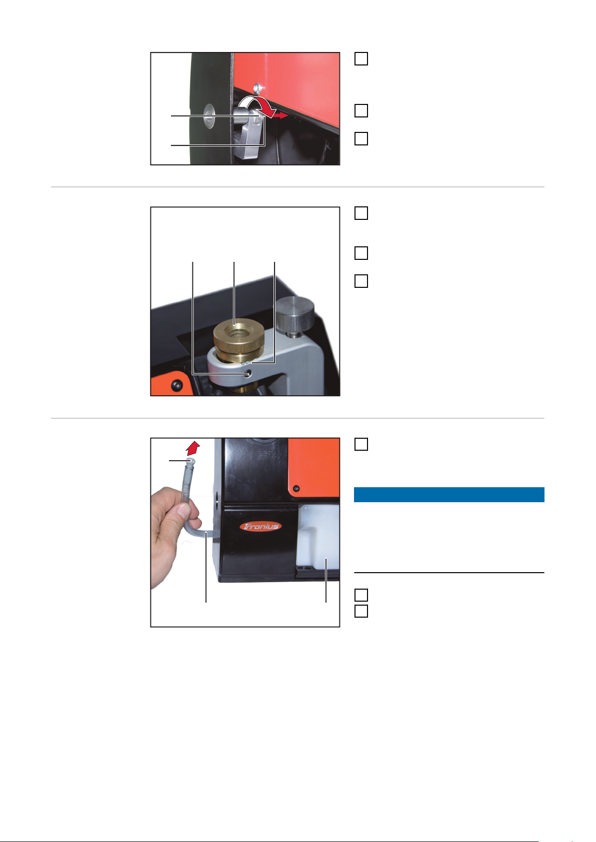
Fitting the
length stop
Turn the knurled nut (1) until the
1
banking screw (2) finishes flush
with the wide side of the stop angle
(3)
Remove the clamping screw (5)
2
and the sleeve (4) from the stop
angle (3)
46
Page 47

3
4
(3)(5)
Insert the stop angle (3) into the
1
2
(1) (2) (3)
3
device from the back
Fix the stop angle (3) in place with
4
the sleeve (4) and the clamping
screw (5)
Fitting the handle for the separator
NOTE!
Make sure that the positioning notch
on the sleeve (4) is at the top and that
the stop angle is at the far right (in the
zero position).
Screw the handle for the separator
1
into the left side of the device and
tighten it
EN
Assembling the
electrode holder
Insert the clamping sleeve (2) with
1
the diameter of the electrode to be
ground into the lower part (3) of
the electrode holder
Screw the top part (1) of the elec-
2
trode holder into the lower part (3),
but do not tighten it
47
Page 48

Adding grinding
(2)(1)
(1)
fluid
Check that the key is holding the
1
tank securely in place
Pour the grinding fluid for the grin-
2
ding device through the guide bushing
The fluid level must lie between
3
the minimum mark (1) and the maximum mark (2)
NOTE!
The grinding fluid is partially absorbed by the disc.
Before each start-up, check the
▶
fluid level and correct it if necessary.
Adjusting the
guide bushing
Turn the guide bushing (1) down as
1
far as the stop
48
Page 49

Start-up
Safety
Setup regulations
Mains connection
WARNING!
Danger from incorrect operation and work that is not carried out properly.
This can result in serious personal injury and damage to property.
All the work and functions described in this document must only be carried
▶
out by technically trained and qualified personnel.
Read and understand this document in full.
▶
Read and understand all safety rules and user documentation for this device
▶
and all system components.
Place the device on a firm and level surface
-
Position the device so that cooling air can flow unhindered through the air
-
ducts underneath and on the back
Ensure that the workplace is adequately lit
-
Do not use the device outdoors
-
The rating plate contains details of the permitted mains voltage and grid frequency and is located on the underside of the housing. The device is only designed for these values.
The mains lead fuse protection specification must be appropriate to the device
output. The device output can be found on the rating plate and in the "Technical
data" section.
The device must only be operated with the pre-fitted mains cable and mains
plug.
EN
Starting up
NOTE!
An inadequately dimensioned electrical installation can cause damage to property.
Dimension the mains lead and its fuse protection to suit the local power sup-
▶
ply.
The technical data shown on the rating plate applies.
Move the main switch to the - O - position
1
Plug in the mains plug
2
Insert the electrode holder into the guide bushing of the grinder to prevent
3
the grinding fluid spraying out
Switch on the device for approx. 5 seconds
4
The grinding fluid will spread through the device
Check the fluid level and top up with grinding fluid if necessary
5
49
Page 50

Grinding the electrode
1
2
2
(1) (2) (3)
6
4
(4)
(5)
General
Preparing the
electrode
NOTE!
To be able to grind an electrode, it must have a minimum length of 30 mm.
Section "Creating an electrode shorter than 25 mm" explains how to process
shorter electrodes.
Insert the electrode (1) into the
1
clamping sleeve of the electrode
holder from the front
Approx. 25 mm of the electro-
-
de must still protrude at the
front
Twist the front part (2) and back
2
part (3) of the electrode holder as
shown and lightly clamp the electrode
The electrode should then not be
able to slip by itself, but it must
still be possible to move it by hand
Open the clamping screw (5)
3
Move the length stop to the zero
4
position
Tighten the clamping screw (5)
5
Insert the electrode holder into
6
the guide bushing (4) of the length
stop as far as the stop
This accurately sets the length
-
of the electrode
Tighten the back part of the elec-
7
trode holder (3)
This clamps the electrode in
-
the electrode holder
50
Page 51

Grinding the
(3) (1)(2)
14°
5
4
electrode
Open the knurled screw (1) and set
1
the angle adjustment (2) to the required angle
Read the set angle on the digi-
-
tal display (3)
NOTE!
The set angle corresponds to half the
tip angle.
In the example shown, a tip angle of
28° would result.
Re-tighten the knurled screw (1)
2
Switch on the device
3
Insert the electrode holder into
4
the guide bushing of the grinding
device
NOTE!
Do not exert any pressure on the electrode during the grinding process.
The weight of the electrode holder is
enough to run the grinding process.
EN
As soon as the electrode makes
5
contact with the grinding disc, turn
the electrode holder slowly
Grinding is completed when
the cone of the electrode hol-
-
der touches the cone of the
guide bushing and
there is no longer any grinding
-
noise
Remove the electrode holder and
6
switch off the device
51
Page 52

Cutting the electrode tip
(1)
(2)
1
2
2
(1) (2) (3)
General To cut an electrode, the correct electrode guide must be fitted on the separator.
The electrode guide fitted at the factory is for electrode diameters 2.4 mm to
3.2 mm.
Changing the
electrode guide
Preparation
If required, unscrew the installed
1
electrode guide (1)
Screw in the required electrode
2
guide (2)
CAUTION!
Danger from electrode guide that is
too big during the cutting process.
This may result in damage to the electrode.
Carry out the cutting process with
▶
the correct electrode guide.
Insert the electrode (1) into the
1
clamping sleeve of the electrode
holder from the front
Approx. 25 mm of the electrode
must still protrude at the front
Twist the front part (2) and back
2
part (3) of the electrode holder as
shown and lightly clamp the electrode
52
The electrode should then not be
able to slip by itself, but it must
still be possible to move it by hand
Page 53

(A)
Set the length stop to the tip
3
3
(3)
(1) (2)
3
length (A)
Insert the electrode holder into
4
the guide bushing of the length
stop as far as the stop
Cutting the electrode tip
This accurately sets the length of
the electrode
Tighten the back part of the elec-
5
trode holder (3)
This clamps the electrode in
-
the electrode holder
Insert the electrode holder (3) into
1
the guide bushing (2) of the separator as far as the stop
Switch on the device
2
Turn the electrode holder (3) and
3
slowly press the handle (1) down
This cuts the electrode
-
Switch off the device
4
EN
NOTE!
Electrode grinding can now start immediately.
It is no longer necessary to set the length.
53
Page 54

Creating an electrode of a specific length
1
2
(2)(1)
3
4
4
(3) (4) (5)
General Electrodes with a specific length of 92 mm or 30 mm can be created with the en-
closed stop pins.
The electrode clamped in the electrode holder is cut to the defined length by the
separator and can then be ground immediately.
Preparation
Place the stop-bolt (2) for the re-
1
quired length into the back part (5)
of the electrode holder
Fix the stop-bolt in place with the
2
M10 screw (1)
Push the electrode (3) into the
3
electrode holder from the front as
far as the stop
Twist the front part (4) and back
4
part (5) of the electrode holder as
shown and tightly clamp the electrode
54
Page 55

Creating an elec-
3
3
(3)
(1) (2)
(3) (1)(2)
14°
trode of a specific length
Insert the electrode holder (3) into
1
the guide bushing (2) of the separator as far as the stop
Switch on the device
2
Turn the electrode holder (3) and
3
slowly press the handle (1) down
This cuts the electrode
-
EN
Grinding the
electrode
Open the knurled screw (1) and set
1
the angle adjustment (2) to the required angle
Read the set angle on the digi-
-
tal display (3)
NOTE!
The set angle corresponds to half the
tip angle.
In the example shown, a tip angle of
28° would result.
Re-tighten the knurled screw (1)
2
Switch on the device
3
55
Page 56

5
4
Insert the electrode holder into
4
the guide bushing of the grinding
device
NOTE!
Do not exert any pressure on the electrode during the grinding process.
The weight of the electrode holder is
enough to run the grinding process.
As soon as the electrode makes
5
contact with the grinding disc, turn
the electrode holder slowly
Grinding is completed when
the cone of the electrode hol-
-
der touches the cone of the
guide bushing and
there is no longer any grinding
-
noise
Remove the electrode holder and
6
switch off the device
56
Page 57

Creating an electrode shorter than 25 mm
1
2
2
(1) (2) (3)
6
4
(4)
(5)
General When creating an electrode shorter than 25 mm, the electrode is first ground as
described in the "Grinding the electrode" section.
The ready-ground electrode is then cut to the required length.
NOTE!
To create an extremely short electrode, the base material must be at least 30
mm longer than the desired final length.
For example: desired final length 10 mm = initial length min. 40 mm
EN
Preparing the
electrode
Insert the electrode (1) into the
1
clamping sleeve of the electrode
holder from the front
Approx. 25 mm of the electro-
-
de must still protrude at the
front
Twist the front part (2) and back
2
part (3) of the electrode holder as
shown and lightly clamp the electrode
The electrode should then not be
able to slip by itself, but it must
still be possible to move it by hand
Open the clamping screw (5)
3
Move the length stop to the zero
4
position
Tighten the clamping screw (5)
5
Insert the electrode holder into
6
the guide bushing (4) of the length
stop as far as the stop
This accurately sets the length
-
of the electrode
Tighten the back part of the elec-
7
trode holder (3)
This clamps the electrode in
-
the electrode holder
57
Page 58

Grinding the
(3) (1)(2)
14°
5
4
electrode
Open the knurled screw (1) and set
1
the angle adjustment (2) to the required angle
Read the set angle on the digi-
-
tal display (3)
NOTE!
The set angle corresponds to half the
tip angle.
In the example shown, a tip angle of
28° would result.
Re-tighten the knurled screw (1)
2
Switch on the device
3
Insert the electrode holder into
4
the guide bushing of the grinding
device
NOTE!
Do not exert any pressure on the electrode during the grinding process.
The weight of the electrode holder is
enough to run the grinding process.
As soon as the electrode makes
5
contact with the grinding disc, turn
the electrode holder slowly
Grinding is completed when
the cone of the electrode hol-
-
der touches the cone of the
guide bushing and
there is no longer any grinding
-
noise
Remove the electrode holder and
6
switch off the device
58
Page 59

Creating an elec-
5
2
(1)
(2)
7
7
(5)
(3) (4)
trode shorter
than 25 mm
Open the clamping screw (2)
1
Set the length stop to the required
2
final length of the electrode +
3 mm
(e.g. final length 10 mm = value set
13 mm)
Tighten the clamping screw (2)
3
Open the electrode holder slightly
4
and pull out more than the set
length of electrode
Insert the electrode holder into
5
the guide bushing (1) of the length
stop as far as the stop
This accurately sets the length of
the electrode
Tighten the back part of the elec-
6
trode holder
This clamps the electrode in
-
the electrode holder
Insert the electrode holder (5) into
5
the guide bushing (4) of the separator as far as the stop
Switch on the device
6
Turn the electrode holder (5) and
7
slowly press the handle (3) down
This cuts the electrode
-
Switch off the device
8
EN
59
Page 60

Creating a blunt electrode tip
1
2
2
(1) (2) (3)
(3) (1)(2)
1
General The practice of blunting a ground electrode tip is used mainly for automated wel-
ding processes.
Blunting the tip increases the service life of the electrode.
Preparation
NOTE!
The electrode tip can only be blunted properly if the electrode has previously
been ground.
See the "Grinding the electrode" section.
Insert the ground electrode (1) in-
1
to the clamping sleeve of the electrode holder from the front
The end with the ground tip should
protrude forwards by about 25 mm
Twist the front part (2) and back
2
part (3) of the electrode holder as
shown and lightly clamp the electrode
The electrode should then not be
able to slip by itself, but it must
still be possible to move it by hand
Creating a blunt
electrode tip
Open the knurled screw (1) and set
1
the angle adjustment (2) to 90°
The set angle can be read on the
digital display (3)
Re-tighten the knurled screw (1)
2
60
Page 61

(5)(4)
4
5
3
5
NOTE!
(4) (5)
8
6
The guide bushing (5) of the grinding
device engages as it is turned in
0.1 mm increments.
Unscrew the guide bushing (5) ap-
3
prox. 2 - 3 mm anti-clockwise (approx. 20 - 30 grid increments)
Insert the electrode holder (4) into
4
the guide bushing of the grinding
device as far as the stop
This accurately sets the length of
the electrode
Twist the front and back parts of
5
the electrode holder (4)
This clamps the electrode
-
Turn the guide bushing (5) anti-
6
clockwise to set the required flattening of the electrode tip
(e.g. 5 grid increments = 0.5 mm
flattening)
Switch on the device
7
Insert the electrode holder as far
8
as the stop
Remove the electrode holder
9
Switch off the device
10
EN
61
Page 62

Fault diagnosis
Faults with the
electrode
Electrode is not ground to a point
Cause:
Remedy:
Cause:
Remedy:
Cause:
Remedy:
Electrode is not ground to a point
Disc wear compensation has already taken place
Cause:
Remedy:
Electrode is not ground to a point
Disc wear compensation has already taken place; all grinding tracks have been
used
Cause:
Remedy:
Guide bushing not in the zero position
Screw the guide bushing of the grinder right in
Length stop somewhat to the right of the zero position
Move the length stop to the zero position
Disc is too worn
Compensate for disc wear by fine adjustment of the length stop
Disc wear has reached the maximum value
Change the grinding track
Grinding disc is worn out
Change the grinding disc
Electrode is ground too much
The electrode is protruding too far out of the electrode holder, so more material
than necessary is ground away from the electrode
Cause:
Remedy:
Cause:
Remedy:
Electrode goes blue during grinding
The electrode is getting too hot during the grinding process
Cause:
Remedy:
Cause:
Remedy:
Length stop is to the left of the zero position
Move the length stop to the zero position
Disc wear compensation was not reset after a grinding disc change
Reset length stop fine adjustment to the zero position
Grinding pressure too high
Do not exert any pressure on the electrode during the grinding pro-
cess. The weight of the electrode holder is enough to run the grinding
process.
Too little grinding fluid in the device
Top up with grinding fluid; see the "Adding grinding fluid" section
62
Page 63

Faults with the
device
The separator does not cut
The electrode is not cut through or is only partially cut
Cause:
Remedy:
Cause:
Remedy:
Cause:
Remedy:
Grinding fluid is escaping
Cause:
Remedy:
Cause:
Remedy:
Cause:
Remedy:
Electrode was not turned enough during cutting
Turn the electrode several more times at the end of the cutting pro-
cess
Cutting wheel is worn out
Change the cutting wheel
The drive belt is faulty
Contact After-Sales Service
Drain hose is not sealed
Seal the tank drain hose and attach it in the collecting cup on the left
side of the device
The seal between the viewing window and the housing is leaking
Drain the grinding fluid; remove the housing cover; clean or change
the seal
The tank seal is leaking
Drain the grinding fluid; remove the tank; clean or change the seal
EN
The digital display is not showing anything
Cause:
Remedy:
Cause:
Remedy:
The battery in the digital display is flat
Change the digital display battery
The digital display is faulty
Contact After-Sales Service
63
Page 64

Troubleshooting
Safety
Troubleshooting
overview
WARNING!
Danger from incorrect operation.
This can result in serious injury and damage to property.
Read and understand these Operating Instructions before using the descri-
▶
bed functions.
Read and understand the safety data sheets of the materials used, especially
▶
the electrodes to be ground, before using the described functions.
WARNING!
Danger from electrical current.
This can result in serious personal injury and damage to property.
Before starting work, switch off all devices and components involved and dis-
▶
connect them from the grid.
Secure all devices and components involved so they cannot be switched back
▶
on.
After opening the device, use a suitable measuring instrument to check that
▶
electrically charged components (such as capacitors) have been discharged.
"Troubleshooting" is composed of the following sections
Required tools and materials
-
Compensating for disc wear
-
Changing the grinding track
-
Draining the grinding fluid
-
Removing the cover plate
-
Changing the grinding disc
-
Changing the cutting wheel
-
Fitting the cover plate
-
Adding grinding fluid
-
Changing the digital display battery
-
Required tools
and materials
Compensating
for disc wear
64
The following tools and materials are required:
2.5 mm Allen key
-
5 mm Allen key (for the grinding disc)
-
6 mm Allen key (for the cutting wheel)
-
TX25 Torx screwdriver
-
A container for the grinding fluid (min. capacity 500 ml)
-
Disc wear is compensated for by a fine adjustment of the length stop.
Page 65

(1)
(2)
Turn the adjusting screw (1) half a
(1)
(2) (3)
(3)(2)
(1)
2
1
turn in the specified direction to
move the stop-bolt (2) backwards
Perform a grinding operation to
2
test the result
Keep performing steps 1 and 2 un-
3
til the result is satisfactory
EN
Changing the
grinding track
Draining the
grinding fluid
Undo the Allen screw (1) using a
1
2.5 mm Allen key
Turn the guide bushing (2) by one
2
notch (3).
Re-tighten the Allen screw (1)
3
Tightening torque = 0.5 Nm
Remove the drain hose (2) from the
1
collecting cup on the left side of
the device
NOTE!
Hold the hose higher than the fill level
inspection glass.
Otherwise grinding fluid will escape as
soon as the seal (1) is opened.
Open the seal (1)
2
Put the hose into a receptacle with
3
a minimum capacity of 500 ml
65
Page 66

Hold the receptacle with the hose
(4)
(5)(3)
4
ower than the top edge of the tank
l
(3) for the grinding fluid.
Allow the grinding fluid t
5
Once the grinding fluid st
6
o escape
ops escaping from the hose, close the seal
(1) again
NOTE!
There will still be some grinding fluid
in the tank.
Onl
y the grinding fluid from the device
housing was removed using the drain
hose
Pull the key (4) for fixing the tank
7
out towards the front
Pull the tank (3) down and out of
8
the housing
Empty the tank completely and
9
ean it
cl
Clean and check the tank seal
-
(5)
Replace the tank and fix it in place
10
with the k
-
Put the drain hose back in the
11
ecting cup
coll
ey
The key must engage audibly
66
Page 67

Removing the
(1) (2) (3) (4) (5) (6)
(2)
(3)
(1)
(4)
cover plate
NOTE!
Before removing the cover plate,
make sure that there is no more grinding fluid in the housing.
Remove the Allen screws (1) ‑ (6)
1
on the cover plate using a 2.5 mm
Allen key
Take off the cover plate and the
2
viewing window
EN
Changing the
grinding disc
Remove the fastening screw (2)
1
from the grinding disc using a
5 mm Allen key
Insert the 2.5 mm Allen key into a
hole (3) in the disc cover (1) to hold
in place
Take off the disc cover (1) and re-
2
move the grinding disc from the
drive shaft
If the grinding disc (4) proves diffi-
3
cult to detach from the drive shaft,
use the 5 mm Allen key to lever
the grinding disc out slightly
Turn the grinding disc a little and
4
repeat the levering action with the
Allen key
Continue this process until the
5
grinding disc can be removed from
the drive shaft
Fit the new grinding disc, replace
6
the disc cover (1) and secure using
the fastening screw (2)
Tightening torque = 5.0 Nm
67
Page 68

NOTE!
(1)(2)(3)
(1) (2) (3) (4) (5) (6)
A compensator may have been fitted to the length stop to counteract the effects of grinding disc wear.
This should be returned to its installation condition whenever a new grinding
▶
disc is fitted (see "Fitting the length stop").
Changing the
cutting wheel
Fitting the cover
plate
Remove the fastening screw (2)
1
from the grinding disc using a
6 mm Allen key
Insert the 2.5 mm Allen key into a
hole (3) in the disc cover (1) to hold
in place
Take off the disc cover (1) and re-
2
move the grinding disc from the
drive shaft
Fit the new cutting wheel, replace
3
the disc cover (1) and secure using
the fastening screw (2)
Tightening torque = 5.0 Nm
Clean the seal between the viewing
1
window and the housing
Fit the viewing window and cover
2
plate
Tighten the Allen screws (1) ‑ (6) on
3
the cover plate using a 2.5 mm Allen key
Tightening torque = 0.5 Nm
68
Page 69

Adding grinding
(2)(1)
fluid
Check that the key is holding the
1
tank securely in place
Pour the grinding fluid for the grin-
2
ding device through the guide bushing
The fluid level must lie between
3
the minimum mark (1) and the maximum mark (2)
NOTE!
The grinding fluid is partially absorbed by the disc.
Before each start-up, check the
▶
fluid level and correct it if necessary.
EN
69
Page 70

Changing the di-
(1) (2)
(3) (4)
(5)
gital display battery
A CR2032 or CR2450 battery will be required.
WARNING!
Danger from incorrectly set belt tension or motor rpm.
This can result in personal injury or damage to property.
Do not alter anything inside the device. Only carry out the tasks specified.
▶
Housing (left side) Housing (right side)
Remove the left and right TX25
1
screws (1) ‑ (4) from the housing
Lift up the housing cover just en-
2
ough to disconnect the ground
conductor (5) from the motor
Place the housing cover next to the
3
device
70
Page 71

(6)
Slide out the battery (6) and re-
4
place with a new CR2032 battery
Fit the new battery so that the negative pole is facing outwards
Connect the ground conductor (5)
5
and replace the housing cover
Refit the left and right TX25
6
screws (1) ‑ (4) on the housing
Tightening torque = 6.0 Nm
EN
71
Page 72

Care, maintenance and disposal
Safety
Danger from incorrect operation.
This can result in serious injury and damage to property.
▶
▶
Danger from electrical current.
This can result in serious personal injury and damage to property.
▶
▶
▶
General Under normal operating conditions, the device only requires a minimum of care
and maintenance. However, it is vital to carry out the procedures described below
to ensure it remains in a usable condition for many years.
WARNING!
Read and understand these Operating Instructions before using the described functions.
Read and understand the safety data sheets of the materials used, especially
the electrodes to be ground, before using the described functions.
WARNING!
Before starting work, switch off all devices and components involved and disconnect them from the grid.
Secure all devices and components involved so they cannot be switched back
on.
After opening the device, use a suitable measuring instrument to check that
electrically charged components (such as capacitors) have been discharged.
Before each
start-up
Every 6 months or each time the grinding disc is changed
Disposal Dispose of in accordance with the applicable national and local regulations.
Visually inspect the moving parts
-
Check the grinding fluid level
-
Change the grinding fluid
-
Thoroughly clean the device
-
Check the condition of the grinding disc
-
Check the condition of the cutting wheel
-
72
Page 73

Technical data
TIG Grinder
Mains voltage 115 - 230 V
Grid frequency 50/60 Hz
Mains fuse 10 A
Motor output 800 W
Rotational speed 9500 rpm
Grinding speed 60 m/s
Grinding disc diameter 100 mm
Cutting wheel diameter approx. 62 mm
Weight 12.8 kg
Permitted electrode diameter
in the standard version: 1.6 mm / 2.4 mm / 3.2 mm
with accessories: 1.0 mm / 2.0 mm / 4.0 mm / 4.8 mm
Digital display battery
Voltage 3 V
Type CR2032 or CR2450
EN
73
Page 74

74
Page 75

Sommaire
Consignes de sécurité 77
Explication des consignes de sécurité 77
Généralités 77
Sources de risques particulières 78
Utilisation conforme à la destination 78
Conditions environnementales 78
Obligations de l'exploitant 79
Personnel technique qualifié et formé 79
Obligations du personnel 79
Entretien et maintenance 79
Droits d'auteur 79
Généralités 81
Description de l'appareil 81
Contenu de la livraison 81
Utilisation conforme à la destination 82
Éléments de commande et connexions 83
Éléments de commande et connecteurs 83
Installation 84
Sécurité 84
Monter la butée de longueur 84
Monter la poignée pour le dispositif de sectionnement 85
Assembler le porte-électrode 85
Remplir le réservoir de liquide de rectification 86
Régler la douille de guidage 86
Mise en service 87
Sécurité 87
Consignes de montage 87
Raccordement au réseau 87
Mise en service 87
Rectifier l'électrode 88
Généralités 88
Préparation de l'électrode 88
Rectifier l'électrode 89
Sectionner la pointe de l'électrode 90
Généralités 90
Changer de guide-électrode 90
Préparation 90
Sectionner la pointe de l'électrode 91
Confectionner une électrode de longueur définie 92
Généralités 92
Préparation 92
Confectionner une électrode de longueur définie 93
Rectifier l'électrode 93
Confectionner une électrode de longueur inférieure à 25 mm 95
Généralités 95
Préparation de l'électrode 95
Rectifier l'électrode 96
Confectionner une électrode de longueur inférieure à 25 mm 97
Confectionner une pointe d'électrode émoussée 98
Généralités 98
Préparation 98
Confectionner une pointe d'électrode émoussée 98
Diagnostic d'erreur 100
Problème sur l'électrode 100
Problèmes sur l'appareil 101
Élimination des erreurs 102
Sécurité 102
Élimination des erreurs - Vue d'ensemble 102
Outils et accessoires nécessaires 102
Compenser l'usure du disque 102
FR
75
Page 76

Changer de trace de rectification 103
Vidanger le liquide de rectification 103
Retirer la plaque de protection 105
Changer le disque de rectification 105
Changer le disque de tronçonnage 106
Monter la plaque de protection 106
Remplir le réservoir de liquide de rectification 107
Remplacer la pile de l'affichage numérique 108
Maintenance, entretien et élimination 110
Sécurité 110
Généralités 110
Avant chaque mise en service 110
Tous les 6 mois 110
Élimination des déchets 110
Caractéristiques techniques 111
TIG Grinder 111
76
Page 77

Consignes de sécurité
Explication des
consignes de
sécurité
DANGER!
Signale un risque de danger immédiat.
S'il n'est pas évité, il peut entraîner la mort ou des blessures graves.
▶
AVERTISSEMENT!
Signale une situation potentiellement dangereuse.
Si elle n'est pas évitée, elle peut entraîner la mort ou des blessures graves.
▶
ATTENTION!
Signale une situation susceptible de provoquer des dommages.
Si elle n'est pas évitée, elle peut entraîner des blessures légères ou minimes,
▶
ainsi que des dommages matériels.
REMARQUE!
Signale la possibilité de mauvais résultats de travail et de dommages sur l'équipement.
FR
Généralités Cet appareil est fabriqué selon l'état actuel de la technique et conformément
aux règles techniques de sécurité en vigueur. Cependant, en cas d'erreur de manipulation ou de mauvaise utilisation, il existe un risque :
de blessure et de mort pour l'utilisateur ou des tiers ;
-
de dommages pour l'appareil et les autres biens de l'exploitant ;
-
d'inefficacité du travail avec l'appareil.
-
Toutes les personnes concernées par la mise en service, l'utilisation, la maintenance et la remise en état de l'appareil doivent :
posséder les qualifications correspondantes ;
-
lire attentivement et suivre avec précision les prescriptions des présentes In-
-
structions de service.
Les Instructions de service doivent être conservées en permanence sur le lieu
d'utilisation de l'appareil. En complément des présentes Instructions de service,
les règles générales et locales en vigueur concernant la prévention des accidents
et la protection de l'environnement doivent être respectées.
Concernant les avertissements de sécurité et de danger présents sur l'appareil,
veiller à :
leur lisibilité permanente ;
-
ne pas les détériorer ;
-
ne pas les retirer ;
-
ne pas les recouvrir, ni coller d'autres autocollants par-dessus, ni les peindre.
-
Les emplacements des avertissements de sécurité et de danger présents sur
l'appareil figurent au chapitre « Généralités » des Instructions de service de l'appareil.
Éliminer les dysfonctionnement qui peuvent menacer la sécurité avant la mise en
service de l'appareil.
77
Page 78

La sécurité est en jeu !
Sources de risques particulières
Tenir les mains, cheveux, vêtements et outils à l'écart des pièces en mouvement,
telles que :
les engrenages ;
-
les galets ;
-
les arbres ;
-
les parties articulées.
-
Ne pas intervenir manuellement dans des pièces d'entraînement en rotation.
Risque d'écrasement !
Ne pas introduire les mains et les autres parties du corps entre des pièces de serrage.
Risque de coupure !
Porter des gants de protection en cas de manipulation d'objets à arêtes vives.
Les capots et les panneaux latéraux peuvent être ouverts/enlevés uniquement
pendant la durée des opérations de maintenance et de réparation.
En cours d'utilisation :
s'assurer que tous les capots sont fermés et que tous les panneaux latéraux
-
sont montés correctement ;
maintenir fermés tous les capots et panneaux latéraux.
-
Utilisation conforme à la destination
Conditions environnementales
Cet appareil est exclusivement destiné à une utilisation dans le cadre d'un emploi
conforme aux règles en vigueur.
Toute autre utilisation est considérée comme non conforme. Le fabricant ne saurait être tenu pour responsable des dommages consécutifs.
Font également partie de l'emploi conforme
la lecture attentive et le respect de toutes les indications et de tous les aver-
-
tissements de sécurité et de danger des Instructions de service
le respect de tous les travaux d'inspection et de maintenance
-
l'installation selon les Instructions de service
-
Tout fonctionnement ou stockage de l'appareil en dehors du domaine indiqué est
considéré comme non conforme. Le fabricant ne saurait être tenu responsable
des dommages consécutifs.
Plage de température pour l'air ambiant :
lors du fonctionnement : + 5 °C à + 40 °C (41 °F à 104 °F)
-
lors du transport et du stockage : -15 °C à +55 °C (5 °F à 131 °F)
-
Humidité relative de l'air :
jusqu'à 50 % à 40 °C (104 °F)
-
jusqu'à 80 % à 20 °C (68 °F)
-
78
Air ambiant : absence de poussières, acides, substances ou dégagements gazeux
corrosifs, etc.
Page 79

Obligations de
l'exploitant
L'exploitant s'engage à laisser travailler sur l'appareil uniquement des personnes
qui
connaissent les dispositions de base relatives à la sécurité du travail et à la
-
prévention des accidents et sont formées à la manipulation de l'appareil
ont attesté par leur signature avoir lu et compris les présentes instructions
-
de service, en particulier le chapitre « Consignes de sécurité »
ont suivi une formation conforme aux exigences relatives aux résultats de
-
travail.
La sécurité de travail du personnel doit être contrôlée à intervalles réguliers.
FR
Personnel technique qualifié et
formé
Obligations du
personnel
Entretien et
maintenance
La mise en service et l'utilisation de l'appareil ne doivent être confiées qu'à un
personnel technique qualifié, ayant suivi une formation correspondante par la société Fronius. C'est la raison pour laquelle les informations des présentes Instructions de service sont exclusivement destinées à ce personnel. N'effectuez pas
d'opérations autres que celles indiquées dans les Instructions de service. Ceci
s'applique même si vous possédez les qualifications correspondantes.
Toutes les personnes qui sont habilitées à travailler avec l'appareil s'engagent,
avant de commencer à travailler
à respecter les dispositions de base relatives à la sécurité du travail et à la
-
prévention des accidents
à lire les présentes instructions de service, en particulier le chapitre « Consi-
-
gnes de sécurité », et à confirmer par leur signature qu'elles les ont comprises et vont les respecter.
Avant de quitter le poste de travail, assurez-vous qu'aucun dommage corporel ou
matériel ne peut survenir, même en votre absence.
Les travaux de réparation et de maintenance doivent être réalisés exclusivement
par des personnes habilitées. Utiliser uniquement les pièces de rechange et
d'usure d'origine (valable également pour les pièces standardisées). Les pièces
provenant d'autres fournisseurs n'offrent pas de garantie de construction et de
fabrication conformes aux exigences de qualité et de sécurité.
Ne réaliser aucune modification, installation ou transformation sur l'appareil sans
autorisation du fabricant.
Les instructions relatives à la maintenance ne dispensent pas de la nécessité de
contrôler l'appareil avec soin et d'éliminer immédiatement les éventuels dysfonctionnements. Le fabricant rejettera tout appel à garantie pour les dommages
consécutifs résultant d'une maintenance mal exécutée ou d'une mauvaise utilisation.
Droits d'auteur Les droits de reproduction des présentes Instructions de service sont réservés
au fabricant.
Les textes et les illustrations correspondent à l'état de la technique lors de l'impression. Sous réserve de modifications. Le contenu des Instructions de service
ne peut justifier aucune réclamation de la part de l'acheteur. Nous vous remerci-
79
Page 80

ons de nous faire part de vos propositions d'amélioration et de nous signaler les
éventuelles erreurs contenues dans les Instructions de service.
80
Page 81

Généralités
(6)
(1)
(7)
(8)
(9)
(10)
(11)
(2)
(3)
(4)
(5)
Description de
l'appareil
Contenu de la livraison
L'appareil sert à appointer et à sectionner la pointe des aiguilles en tungstène utilisées comme électrodes pour les torches TIG.
L'angle de la pointe est réglage en continu et son affichage est numérique.
Le dispositif de détachement permet de confectionner des électrodes à la
longueur minimale désirée.
La rectification s'effectue sur le côté plat du disque de rectification dans le sens
longitudinal de l'électrode. Il est ainsi possible d'obtenir une configuration optimale de la pointe
Pour augmenter la durée de vie du disque de rectification, il est possible de choisir entre 3 traces de rectification.
Le porte-électrode permet de positionner précisément les électrodes pendant la
rectification. Ceci garantit une confection précise et reproductible de la pointe
de l'électrode.
Une douille de serrage propre existe pour chaque diamètre d'électrode afin de
garantir une bonne fixation dans le porte-électrode.
Le liquide de rectification utilisé et le bac de récupération permettent d'éviter les
émissions de poussières dues à la rectification.
Les éléments suivants sont livrés en complément de l'appareil de base :
(1) Poignée pour le dispositif de
sectionnement
(2) Vis M10 pour le goujon d'arrêt
(3) Partie arrière du porte-électro-
de
(4) Partie avant du porte-électrode
(5) Butée de longueur
(6) Douille de serrage 3,2 mm
(7) Douille de serrage 2,4 mm
(8) Douille de serrage 1,6 mm
(9) Goujon d'arrêt pour électrode
30 mm
(10) Goujon d'arrêt pour électrode
92 mm
(11) Guide-électrode 1,0 - 1,6 mm
FR
Non illustrés :
Liquide de rectification 250 ml
-
Liquide de rectification 500 ml
-
REMARQUE!
En cas de besoin, les fiches techniques de sécurité pour le liquide de rectification peuvent être demandées au fabricant.
Guide-électrode 2,4 - 3,2 mm
-
(déjà monté sur la face arrière du
dispositif de sectionnement)
81
Page 82

Utilisation conforme à la destination
L'appareil est exclusivement prévu pour la rectification et/ou pour le sectionnement des électrodes en tungstène. Toute autre utilisation sera considérée non
conforme. Le fabricant ne saurait être tenu pour responsable des dommages
consécutifs
82
Page 83
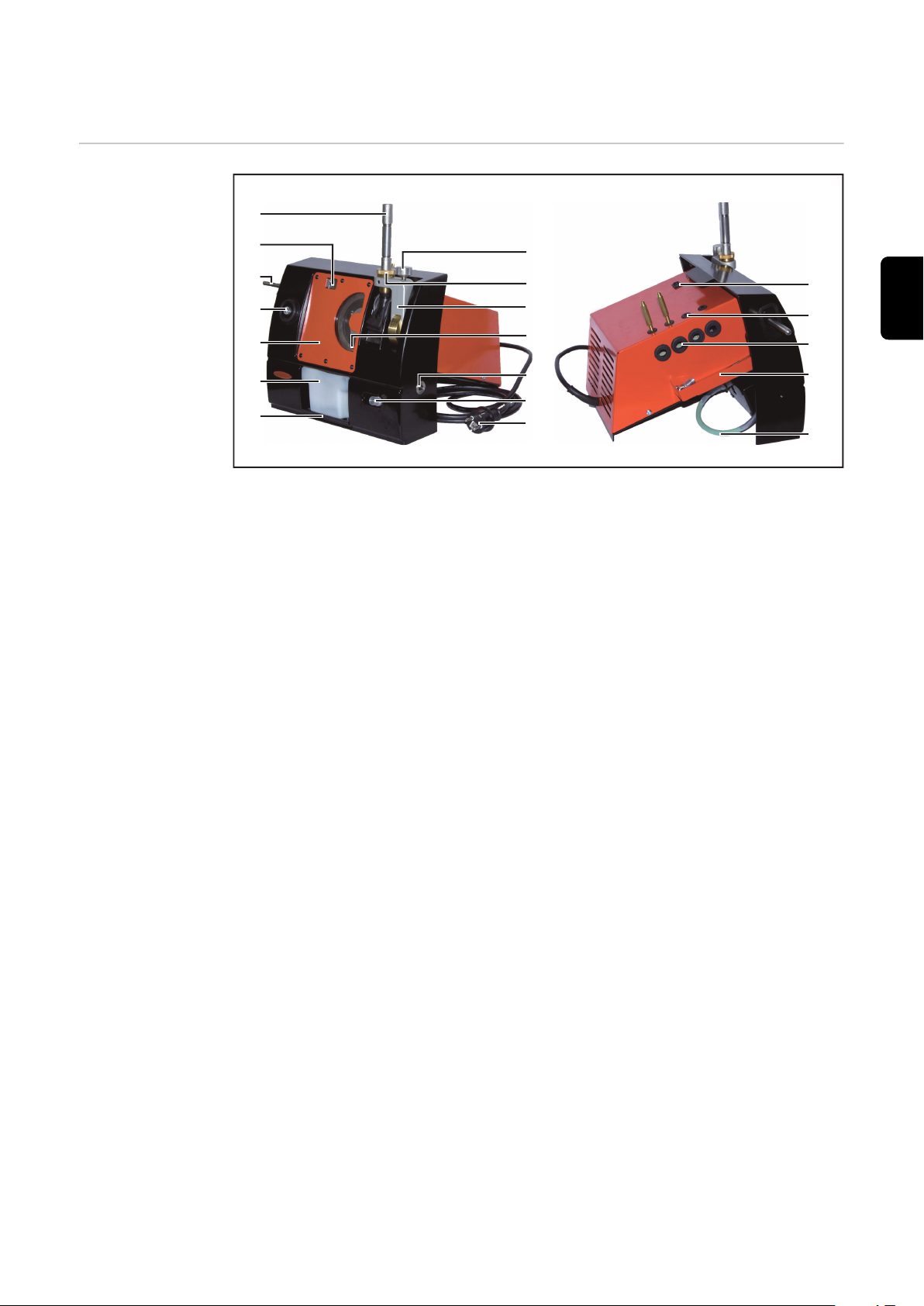
Éléments de commande et connexions
(1)
(9)
(2)
(3)
(4)
(5)
(6)
(7)
(10)
(11)
(13)
(12)
(8)
(15)
(16)
(16)
(17)
(18)
(14)
Éléments de
commande et
connecteurs
FR
(1) Porte-électrode
(2) Affichage numérique
(3) Poignée pour le dispositif de
sectionnement
(4) Douille de guidage du dispositif
de sectionnement
(5) Plaque de protection
(6) Réservoir du liquide de rectifi-
cation
(7) Cale de fixation du réservoir
(8) Vis moletée pour la fixation du
réglage d'angle
(9) Douille de guidage du dispositif
de rectification
(10) Réglage d'angle
(11) Indicateur de niveau
(12) Douille de guidage de la butée
de longueur
(13) Butée de longueur
(14) Fiche secteur
(15) Interrupteur principal
(16) Rangement des outils
(17) Bac de récupération
(18) Tuyau de vidange du réservoir
83
Page 84

Installation
(1)
(2)
(3)
(4)
(5)
Sécurité
AVERTISSEMENT!
Danger dû à une erreur de manipulation et d'erreur en cours d'opération.
Cela peut entraîner des dommages corporels et matériels graves.
Toutes les fonctions et tous les travaux décrits dans le présent document
▶
doivent uniquement être exécutés par du personnel techniquement qualifié.
Ce document doit être lu et compris dans son intégralité.
▶
Lire et comprendre toutes les consignes de sécurité et la documentation uti-
▶
lisateur de cet appareil et de tous les composants périphériques.
AVERTISSEMENT!
Risque d'électrocution.
Cela peut entraîner des dommages corporels et matériels graves.
Avant d'entamer les travaux, déconnecter tous les appareils et composants
▶
concernés et les débrancher du réseau électrique.
S'assurer que tous les appareils et composants concernés ne peuvent pas
▶
être remis en marche.
Après ouverture de l'appareil, s'assurer, à l'aide d'un appareil de mesure ap-
▶
proprié, que les composants à charge électrique (condensateurs, par ex.)
sont déchargés.
Monter la butée
de longueur
Tourner l'écrou moletée (1) jusqu'à
1
ce que la vis de butée (2) soit affleurante avec la face large de
l'équerre de butée (3)
Retirer la vis de serrage (5) et la
2
douille (4) de l'équerre de butée (3)
84
Page 85

3
4
(3)(5)
Mettre en place l'équerre de butée
1
2
(1) (2) (3)
3
(3) dans l'appareil par l'arrière
Fixer l'équerre de butée (3) avec la
4
douille (4) et la vis de serrage (5)
REMARQUE!
Veiller à ce que l'encoche de réglage
de la douille (4) soit en haut et que
l'équerre de butée se trouve tout à fait
à droite (en position zéro).
FR
Monter la
poignée pour le
dispositif de sectionnement
Assembler le
porte-électrode
Visser la poignée pour le dispositif
1
de sectionnement sur le côté gauche de l'appareil et serrer
Placer la douille de serrage (2) cor-
1
respondant au diamètre de l'électrode à rectifier dans la partie
inférieure (3) du porte-électrode
Visser la partie supérieure (1) du
2
porte-électrode dans la partie
inférieure (3), mais ne pas serrer
complètement
85
Page 86
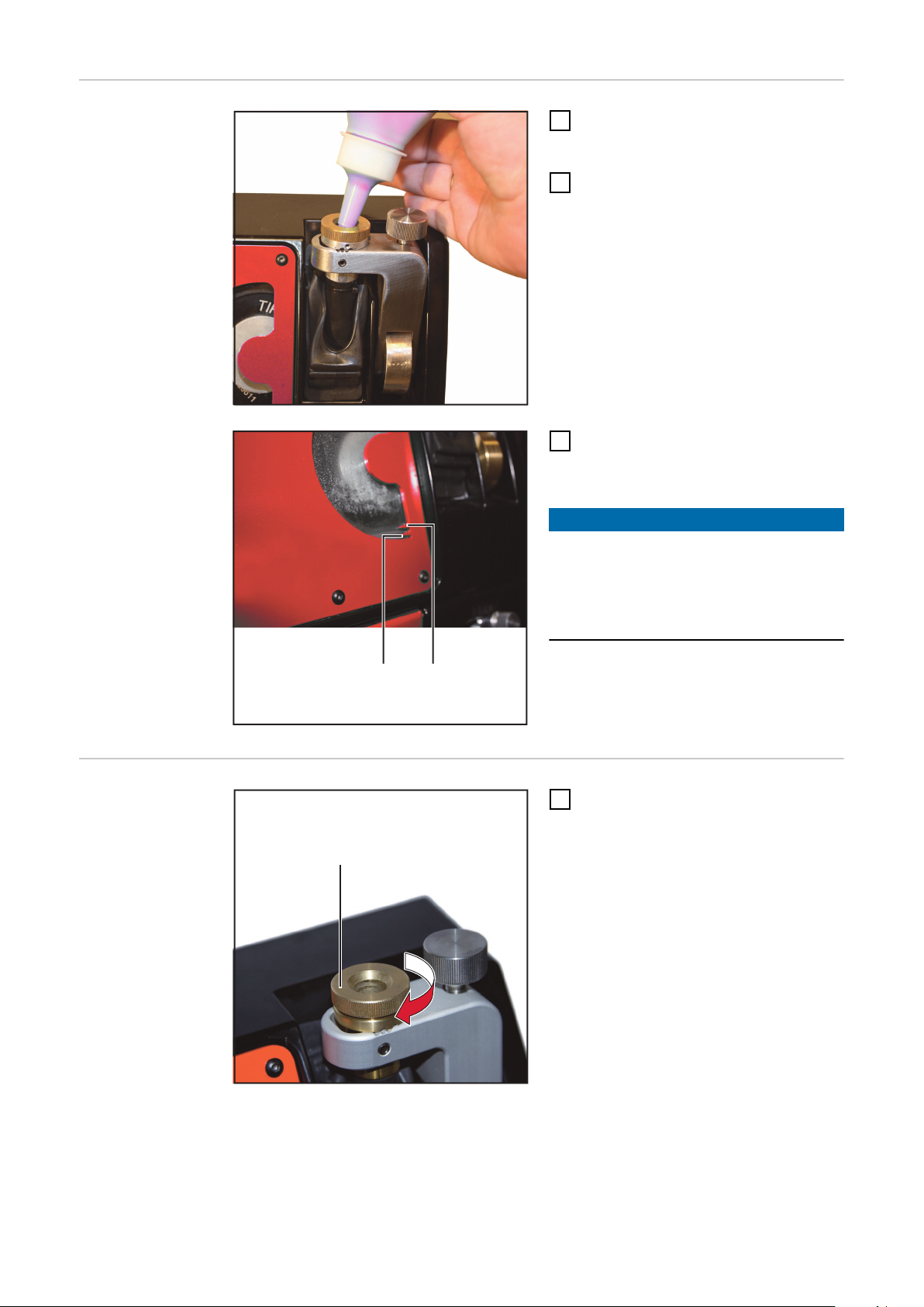
Remplir le réser-
(2)(1)
(1)
voir de liquide de
rectification
Vérifier si la cale de fixation du
1
réservoir est correctement en
place
Remplir avec le liquide de rectifica-
2
tion par la douille de guidage pour
le dispositif de rectification
Le niveau de liquide doit se trouver
3
entre le repère Min. (1) et le repère
Max. (2)
REMARQUE!
Le liquide de rectification est en partie
absorbé par la rondelle.
Avant chaque mise en service,
▶
vérifier le niveau de liquide et le
corriger si nécessaire.
Régler la douille
de guidage
Tourner la vis de guidage (1) vers le
1
bas jusqu'à la butée
86
Page 87

Mise en service
Sécurité
Consignes de
montage
Raccordement
au réseau
AVERTISSEMENT!
Danger dû à une erreur de manipulation et d'erreur en cours d'opération.
Cela peut entraîner des dommages corporels et matériels graves.
Toutes les fonctions et tous les travaux décrits dans le présent document
▶
doivent uniquement être exécutés par du personnel techniquement qualifié.
Ce document doit être lu et compris dans son intégralité.
▶
Lire et comprendre toutes les consignes de sécurité et la documentation uti-
▶
lisateur de cet appareil et de tous les composants périphériques.
Installer l'appareil sur une surface stable et plane
-
Placer l'appareil de manière à ce que l'air de refroidissement puisse circuler
-
sans problème par les fentes d’aération placées sur la face inférieure et au
dos de l’appareil
Veiller à assurer un éclairage suffisant au poste de travail
-
Ne pas utiliser l'appareil à l'air libre
-
La plaque signalétique indiquant la tension du secteur et la fréquence de réseau
admissibles se trouve sur la face inférieure de l'appareil. L'appareil n'est conçu
que pour ces valeurs.
La protection par fusible de la ligne d'alimentation doit être déterminée en fonction de la puissance de l'appareil. La puissance de l'appareil figure sur la plaque
signalétique ainsi qu'à la section « Caractéristiques technique ».
Le fonctionnement de l'appareil n'est autorisé qu'avec le câble secteur et la fiche
réseau montés d'usine.
FR
Mise en service
REMARQUE!
Une installation électrique insuffisamment dimensionnée peut être à l'origine
de dommages sur l'appareil.
Configurer la ligne d'alimentation et son fusible de manière adéquate par
▶
rapport à l'alimentation en courant disponible.
Les spécifications techniques valables sont celles de la plaque signalétique.
Commuter l'interrupteur principal en position - O -
1
Brancher la fiche secteur
2
Placer le porte-électrode dans la douille de guidage du dispositif de rectifica-
3
tion afin d'éviter d'éventuelles projections de liquide de rectification
Connecter l'appareil pendant env. 5 s
4
Le liquide de rectification se répartit dans l'appareil
Vérifier le niveau de liquide de rectification et compléter en cas de besoin
5
87
Page 88

Rectifier l'électrode
1
2
2
(1) (2) (3)
6
4
(4)
(5)
Généralités
Préparation de
l'électrode
REMARQUE!
Pour pouvoir rectifier une électrode, elle doit avoir une longueur minimale de
30 mm.
Le traitement d'électrodes plus courtes est décrit dans la section « Confection
d'une électrode de longueur inférieure à 25 mm ».
Insérer l'électrode (1) par l'avant
1
dans la douille de serrage du porte-électrode
L'électrode doit ressortir de-
-
vant d'env. 25 mm
Tourner la partie avant (2) et la
2
partie arrière (3) du porte-électrode tel qu'indiqué sur l'illustration
et ne serrer l'électrode que légèrement
L'électrode ne doit pas glisser d'elle-même, mais elle doit pouvoir
être déplacée manuellement
Desserrer la vis de serrage (5)
3
Placer la butée de longueur en po-
4
sition zéro
Serrer la vis de serrage (5)
5
Insérer le porte-électrode jusqu'à
6
la butée dans la douille de guidage
(4) de la butée de longueur
La longueur de l'électrode est
-
ainsi exactement réglée
Visser et serrer la partie arrière du
7
porte-électrode (3)
L'électrode est serrée dans le
-
porte-électrode
88
Page 89

Rectifier l'élec-
(3) (1)(2)
14°
5
4
trode
Ouvrir la vis moletée (1) et régler le
1
réglage d'angle (2) à l'angle souhaité
Lire l'angle réglé sur l'affichage
-
numérique (3)
REMARQUE!
L'angle réglé correspond à la moitié de
l'angle de pointe.
Dans l'exemple illustré, l'angle de pointe serait de 28°.
Resserrer la vis moletée (1)
2
Allumer l'appareil
3
Insérer le porte-électrode dans la
4
douille de guidage du dispositif de
rectification
REMARQUE!
Durant la rectification, n'exercer aucune pression sur l'électrode
Le poids du porte-électrode est suffisant pour que la rectification soit
exécutée.
FR
Dès que l'électrode entre en conta-
5
ct avec le disque de rectification,
tourner lentement le porte-électrode
La rectification est terminée dès
lors que :
le cône du porte-électrode
-
touche le cône de la douille de
guidage et
qu'aucun bruit de rectification
-
n'est audible.
Retirer le porte-électrode et
6
déconnecter l'appareil
89
Page 90

Sectionner la pointe de l'électrode
(1)
(2)
1
2
2
(1) (2) (3)
Généralités Pour sectionner la pointe d'une électrode, le guide-électrode approprié doit être
installé sur le dispositif de détachement.
D'usine, le guide-électrode monté est destiné aux électrodes de diamètre 2,4 mm
à 3,2 mm.
Changer de guide-électrode
Préparation
En cas de besoin, dévisser le guide-
1
électrode (1) en place
Visser le guide-électrode approprié
2
(2)
ATTENTION!
Danger dû à un guide-électrode trop
grand lors du processus de sectionnement.
Cela peut endommager l'électrode.
Effectuer la procédure de section-
▶
nement avec le guide-électrode
correct.
Insérer l'électrode (1) par l'avant
1
dans la douille de serrage du porte-électrode
L'électrode doit ressortir devant
d'env. 25 mm
Tourner la partie avant (2) et la
2
partie arrière (3) du porte-électrode tel qu'indiqué sur l'illustration
et ne serrer l'électrode que légèrement
90
L'électrode ne doit pas glisser d'elle-même, mais elle doit pouvoir
être déplacée manuellement
Page 91

(A)
Régler la butée de longueur à la
3
3
(3)
(1) (2)
3
longueur de la pointe (A)
Insérer le porte-électrode jusqu'à
4
la butée dans la douille de guidage
de la butée de longueur
La longueur de l'électrode est ainsi
exactement réglée
Visser et serrer la partie arrière du
5
porte-électrode (3)
L'électrode est serrée dans le
-
porte-électrode
FR
Sectionner la
pointe de l'électrode
Insérer le porte-électrode (3) jus-
1
qu'à la butée dans la douille de guidage (2) du dispositif de sectionnement
Allumer l'appareil
2
Tourner le porte-électrode (3) et
3
pousser lentement la poignée (1)
vers le bas
L'électrode est sectionnée
-
Éteindre l'appareil
4
REMARQUE!
L'électrode peut maintenant être rectifiée immédiatement
Le réglage de la longueur n'est plus nécessaire.
91
Page 92

Confectionner une électrode de longueur définie
1
2
(2)(1)
3
4
4
(3) (4) (5)
Généralités Les goujons d'arrêt joints permettent de confectionner des électrodes d'une
longueur définie de 92 mm ou 30 mm.
L'électrode maintenue dans le porte-électrode est sectionnée à la longueur définie à l'aide du dispositif de sectionnement et peut ensuite être immédiatement
rectifiée.
Préparation
Placer le goujon d'arrêt (2) pour la
1
longueur définie dans la partie arrière (5) du porte-électrode
Fixer le goujon d'arrêt avec la vis
2
M10 (1)
Glisser l'électrode (3) jusqu'à la
3
butée par l'avant dans le porteélectrode
Tourner la partie avant (4) et la
4
partie arrière (5) du porte-électrode tel qu'indiqué sur l'illustration
et bien serrer l'électrode
92
Page 93

Confectionner
3
3
(3)
(1) (2)
(3) (1)(2)
14°
une électrode de
longueur définie
Insérer le porte-électrode (3) jus-
1
qu'à la butée dans la douille de guidage (2) du dispositif de sectionnement
Allumer l'appareil
2
Tourner le porte-électrode (3) et
3
pousser lentement la poignée (1)
vers le bas
L'électrode est sectionnée
-
FR
Rectifier l'électrode
Ouvrir la vis moletée (1) et régler le
1
réglage d'angle (2) à l'angle souhaité
Lire l'angle réglé sur l'affichage
-
numérique (3)
REMARQUE!
L'angle réglé correspond à la moitié de
l'angle de pointe.
Dans l'exemple illustré, l'angle de pointe serait de 28°.
Resserrer la vis moletée (1)
2
Allumer l'appareil
3
93
Page 94

5
4
Insérer le porte-électrode dans la
4
douille de guidage du dispositif de
rectification
REMARQUE!
Durant la rectification, n'exercer aucune pression sur l'électrode
Le poids du porte-électrode est suffisant pour que la rectification soit
exécutée.
Dès que l'électrode entre en conta-
5
ct avec le disque de rectification,
tourner lentement le porte-électrode
La rectification est terminée dès
lors que :
le cône du porte-électrode
-
touche le cône de la douille de
guidage et
qu'aucun bruit de rectification
-
n'est audible.
Retirer le porte-électrode et
6
déconnecter l'appareil
94
Page 95

Confectionner une électrode de longueur inféri-
1
2
2
(1) (2) (3)
6
4
(4)
(5)
eure à 25 mm
Généralités Lors de la confection d'une électrode de longueur inférieure à 25 mm, l'électrode
est d'abord rectifiée tel que décrit à la section « Rectifier l'électrode ».
L'électrode rectifiée est ensuite sectionnée à la longueur souhaitée.
Préparation de
l'électrode
REMARQUE!
Pour confectionner une électrode très courte, le matériau initial doit être d'au
moins 30 mm plus long que la longueur finale.
Par ex. : longueur finale souhaitée 10 mm = longueur initiale min. 40 mm
Insérer l'électrode (1) par l'avant
1
dans la douille de serrage du porte-électrode
L'électrode doit ressortir de-
-
vant d'env. 25 mm
Tourner la partie avant (2) et la
2
partie arrière (3) du porte-électrode tel qu'indiqué sur l'illustration
et ne serrer l'électrode que légèrement
L'électrode ne doit pas glisser d'elle-même, mais elle doit pouvoir
être déplacée manuellement
FR
Desserrer la vis de serrage (5)
3
Placer la butée de longueur en po-
4
sition zéro
Serrer la vis de serrage (5)
5
Insérer le porte-électrode jusqu'à
6
la butée dans la douille de guidage
(4) de la butée de longueur
La longueur de l'électrode est
-
ainsi exactement réglée
Visser et serrer la partie arrière du
7
porte-électrode (3)
L'électrode est serrée dans le
-
porte-électrode
95
Page 96

Rectifier l'élec-
(3) (1)(2)
14°
5
4
trode
Ouvrir la vis moletée (1) et régler le
1
réglage d'angle (2) à l'angle souhaité
Lire l'angle réglé sur l'affichage
-
numérique (3)
REMARQUE!
L'angle réglé correspond à la moitié de
l'angle de pointe.
Dans l'exemple illustré, l'angle de pointe serait de 28°.
Resserrer la vis moletée (1)
2
Allumer l'appareil
3
Insérer le porte-électrode dans la
4
douille de guidage du dispositif de
rectification
REMARQUE!
Durant la rectification, n'exercer aucune pression sur l'électrode
Le poids du porte-électrode est suffisant pour que la rectification soit
exécutée.
Dès que l'électrode entre en conta-
5
ct avec le disque de rectification,
tourner lentement le porte-électrode
La rectification est terminée dès
lors que :
le cône du porte-électrode
-
touche le cône de la douille de
guidage et
qu'aucun bruit de rectification
-
n'est audible.
Retirer le porte-électrode et
6
déconnecter l'appareil
96
Page 97

Confectionner
5
2
(1)
(2)
7
7
(5)
(3) (4)
une électrode de
longueur inférieure à 25 mm
Desserrer la vis de serrage (2)
1
Régler la butée de longueur à la
2
longueur finale souhaitée de l'électrode + 3 mm
(p. ex. longueur finale 10 mm = valeur de réglage 13 mm)
Serrer la vis de serrage (2)
3
Ouvrir légèrement le porte-élec-
4
trode et retirer l'électrode plus que
de la longueur réglée
Insérer le porte-électrode jusqu'à
5
la butée dans la douille de guidage
(1) de la butée de longueur
La longueur de l'électrode est ainsi
exactement réglée
Visser et serrer la partie arrière du
6
porte-électrode
L'électrode est serrée dans le
-
porte-électrode
Insérer le porte-électrode (5) jus-
5
qu'à la butée dans la douille de guidage (4) du dispositif de sectionnement
Allumer l'appareil
6
Tourner le porte-électrode (5) et
7
pousser lentement la poignée (3)
vers le bas
L'électrode est sectionnée
-
Éteindre l'appareil
8
FR
97
Page 98
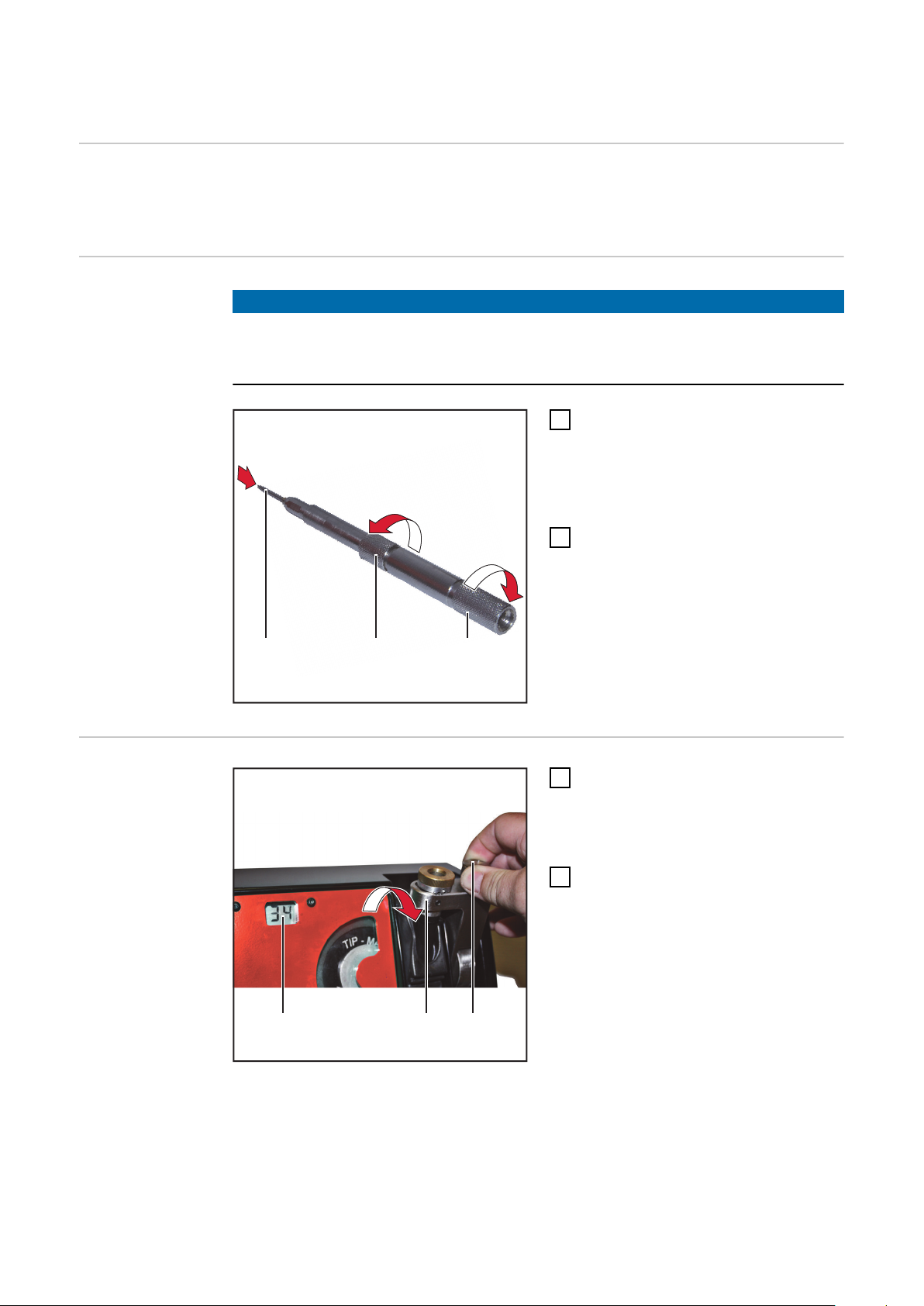
Confectionner une pointe d'électrode émoussée
1
2
2
(1) (2) (3)
(3) (1)(2)
1
Généralités L'utilisation des pointes d'électrodes émoussées est plus particulièrement
réservée aux procédés de soudage automatisés.
Une pointe émoussée prolonge la durée de vie de l'électrode.
Préparation
REMARQUE!
Pour émousser correctement la pointe d'électrode, il est nécessaire que celle-ci
ait été rectifiée auparavant.
Voir la section « Rectifier l'électrode ».
Insérer l'électrode rectifiée (1) par
1
l'avant dans la douille de serrage
du porte-électrode
L'extrémité de la pointe rectifiée
doit ressortir devant d'env. 25 mm
Tourner la partie avant (2) et la
2
partie arrière (3) du porte-électrode tel qu'indiqué sur l'illustration
et ne serrer l'électrode que légèrement
L'électrode ne doit pas glisser d'elle-même, mais elle doit pouvoir
être déplacée manuellement
Confectionner
une pointe
d'électrode
émoussée
Ouvrir la vis moletée (1) et régler le
1
réglage d'angle (2) à 90°
La valeur d'angle réglée s'affiche
sur l'affichage numérique (3)
Resserrer la vis moletée (1)
2
98
Page 99

(5)(4)
4
5
3
5
REMARQUE!
(4) (5)
8
6
La douille de guidage (5) du dispositif
de rectification s'enclenche en tournant par pas de 0,1 mm.
Tourner la douille de guidage (5)
3
d'environ 2 - 3 mm dans le sens
contraire des aiguilles d'une montre (env. 20 - 30 crans)
Insérer le porte-électrode (4) jus-
4
qu'à la butée dans la douille de guidage du dispositif de rectification
La longueur de l'électrode est ainsi
exactement réglée
Tourner la partie avant et la partie
5
arrière du porte-électrode (4)
L'électrode est serrée
-
Tourner la douille de guidage (5)
6
dans le sens horaire pour régler le
méplat souhaité sur la pointe
d'électrode
(p. ex. 5 crans = 0,5 mm de méplat)
Allumer l'appareil
7
Insérer le porte-électrode jusqu'à
8
la butée
Retirer le porte-électrode
9
Éteindre l'appareil
10
FR
99
Page 100

Diagnostic d'erreur
Problème sur
l'électrode
La pointe de l'électrode n'est pas correctement rectifiée
Cause :
Remède :
Cause :
Remède :
Cause :
Remède :
La pointe de l'électrode n'est pas correctement rectifiée
La compensation de l'usure du disque a déjà été effectuée
Cause :
Remède :
La pointe de l'électrode n'est pas correctement rectifiée
L'usure du disque de rectification a atteint sa valeur maximale ; toutes les traces
de rectification ont été utilisées
La douille de guidage n'est pas en position zéro
Visser complètement la douille de guidage du dispositif de rectificati-
on
La butée de longueur est positionnée un peu à droite de la position
zéro
Placer la butée de longueur en position zéro
Le disque de rectification est trop usé
Compenser l'usure du disque de rectification par un réglage très
précis de la longueur
L'usure du disque de rectification a atteint sa valeur maximale
Changer de trace de rectification
Cause :
Remède :
La rectification de l'électrode est trop importante
L'électrode dépasse trop du porte-électrode. La quantité de matériau rectifiée
est trop importante.
Cause :
Remède :
Cause :
Remède :
L'électrode bleuit pendant la rectification
L'électrode chauffe trop pendant la rectification
Cause :
Remède :
Cause :
Remède :
Le disque de rectification est complètement usé
Changer le disque de rectification
La butée de longueur est positionnée à gauche de la position zéro
Placer la butée de longueur en position zéro
La compensation de l'usure du disque de rectification n'a pas été remise à zéro après le changement de disque de rectification
Réinitialiser le réglage précis de la butée de longueur en position zéro
Pression de rectification trop élevée
Durant la rectification, n'exercer aucune pression sur l'électrode Le
poids du porte-électrode est suffisant pour que la rectification soit
exécutée.
Quantité de liquide de rectification insuffisante dans l'appareil
Compléter le liquide de rectification ; voir section « Remplir le réser-
voir de liquide de rectification »
100
 Loading...