

The Impact of Optimizers for
PV
-Modules
A comparative study
Assc. Prof. Dr. W.
Research report, May 2019
SDU ELECTRICAL ENGINEERING
-Toke Franke

THE IMPACT OF OPTIMIZERS FOR PV-MODULES
1
Summary
This study shows that PV systems have typically a higher yield if no module optimizers are applied.
To demonstrate that, extreme scenarios have been chosen where optimizers are expected to bring
the highest benefits. But only for some small niches where complete PV modules have significantly
different irradiation at any given time, do the optimizers help produce more energy than they actually consume.

THE IMPACT OF OPTIMIZERS FOR PV-MODULES
2
Contents
1 Introduction ............................................................................................................................. 3
1.1 Concepts for PV-Inverters ............................................................................................... 3
1.2 String Inverters ................................................................................................................ 3
1.3 Maximum Power Point Tracker ........................................................................................ 4
1.4 Module Optimizer ............................................................................................................ 5
1.5 Purpose of the Investigation ............................................................................................ 5
1.6 The Test setup ................................................................................................................ 6
1.6.1 The Test Site .......................................................................................................... 6
1.6.2 PV inverter system selection .................................................................................. 6
1.7 Data Acquisition .............................................................................................................. 7
2 Test Results ............................................................................................................................. 8
2.1 Scenario with no shadow ................................................................................................. 8
2.1.1 Period ..................................................................................................................... 8
2.1.2 Sunny Day .............................................................................................................. 9
2.1.3 Cloudy Day ........................................................................................................... 10
2.1.4 Conclusion ........................................................................................................... 11
2.2 Scenario with different irradiation at one module ........................................................... 12
2.2.1 Period ................................................................................................................... 12
2.2.2 Sunny Day ............................................................................................................ 13
Cloudy Day ........................................................................................................... 14
2.2.3
2.2.4 Conclusion ........................................................................................................... 15
2.3 Scenario with moving shadow over the day ................................................................... 16
2.3.1 Period ................................................................................................................... 16
2.3.2 Sunny Day ............................................................................................................ 17
2.3.3 Cloudy Day with many changes between sun and clouds .................................... 18
2.3.4 Overcast Day without sunshine ............................................................................ 19
2.3.5 Conclusion ........................................................................................................... 19
2.4 Energy production over one year ................................................................................... 20
3 Final Conclusion.................................................................................................................... 21

THE IMPACT OF OPTIMIZERS FOR PV-MODULES
3
1 Introduction
1.1 Concepts for PV-Inverters
In general PV-inverters can be categorized according to their topologies [1]:
• Module integrated inverters: Each PV-module has its own PV inverter with a single-phase grid
connection and a typical power range of 50 to 400 W.
• String Inverters: A String of several PV-modules is connected to one inverter with a singlephase grid connection and a typical power range of 0,4 to 5 kW.
• Multistring inverters: One or more strings are connected to one inverter often with individual
maximum power point trackers (MPPT). The grid connection can be single- or three-phase depending on the power rating that is typically between 1,5 and 150 kW
• Central inverter: Multiple strings are connected to one MPP-Tracker. The inverter has a threephase grid connection and a power rating between 100 and 5000 kW.
In this report the focus is on residential and commercial string inverters.
1.2 String Inverters
The general concept of a string inverter is shown in Figure 1. The PV generator consists of several
identical PV-modules which are connected in series to a PV-string. The number of PV modules per
string is given by the minimum and maximum input voltage of the inverter. To increase the input
range of the inverter to lower voltages, it often has a boost converter at the input stage that ensures that the DC to AC inverter stage has always a sufficient input voltage to feed energy to the
grid.

THE IMPACT OF OPTIMIZERS FOR PV-MODULES
4
Figure 1: String concept
Figure 2: Voltage-Current-Power Characteristic
1.3 Maximum Power Point Tracker
The electric characteristic of a solar module and thereby also the characteristic of a PV string is
shown in Figure 2 [2]. The curve shows that for a certain voltage a certain current can be drawn
from the string. For the maximum current (short circuit current) the voltage is zero and for the maximum voltage (Open circuit voltage) the current is zero. In both cases also the power is zero, so
that no energy can be produced. To find the current and voltage with the maximum power, the area
below the curve need to be maximal [3].
The maximum power point tracker controls the current in a way such that the maximum power is
always obtained from the PV-string. If the irradiation changes the MPPT finds the new maximum
power point. For conventional MPPT the technique works very well if all PV modules have the
same irradiation meaning no shading and the same orientation. If the irradiation changes at only a
few PV-modules for example due to partial shading the curve changes as shown in Figure 3.
Figure 3: PV-Power with partial shading
The conventional maximum power point tracker might now only find a local maximum, shown as
LMPP on Figure 3, and thereby the inverter does not deliver the maximum possible energy. Advanced MPPT have the purpose to ensure that the PV generator finds the global maximum

THE IMPACT OF OPTIMIZERS FOR PV-MODULES
5
operating point, shown above as GMPP, by performing a sweep over the complete voltage range.
Such a sweep needs to be executed from time to time since the shading might change over the
day and, depending on the shadow, the tracker might find only a local MPP after a cloud passes
the string. Different orientations of the PV modules have similar effect as shading.
1.4 Module Optimizer
Module optimizers or module-level power electronics (MLPE) have the purpose to ensure that each
module is always working in its optimal operating point [4]. Therefore, an additional device – the
optimizer – is connected to each PV module. The typical functions of an optimizer are:
• Local MPP-Tracking for each module
• Disconnection of the module to limit the system voltage in case of a failure
• Monitoring on module level
But module optimizers also come with a few drawbacks:
• MLPE have an energy self-consumption that leads to additional power losses in both the
additional connectors and more significant in the internal power electronics
• Any electrical connector is a potential failure source (fire or breakdown of string), especially
if connectors from different manufacturer are applied (this is typically the case, since PV
modules and MLPEs are coming from different companies)
• An increase in the number of components also increases the risk that one of the components fails
There are different solutions available on the market: Some follow a universal approach, so that
the optimizers work in an open ecosystem and can be connected to nearly any PV-inverter (e.g.
Tigo). Other follow a proprietary concept, where the MLPEs and PV-inverters operate in a closed
ecosystem (e.g. SolarEdge).
1.5 Purpose of the Investigation
As described in section 1.4 optimizers have a couple of advantages and disadvantages. This research project is to better understand the total effect on the energy production of different inverteroptimizer systems in relation to an inverter with advanced power point tracking.
Therefore, three different scenarios are investigated:
• The first scenario represents an optimal installation where all PV panels have the same irradiation and no shadows occur (Chapter 2.1).
• The second scenario simulates a niche application where one PV-module has always a different irradiation than the others. This is achieved by covering one module with a thin and
semi-transparent blanket, while the remaining 13 modules of each string have the full irradiation (Figure 8). An application for that could be that this module has a different orientation
compared to the rest of the string. (Chapter 2.2)
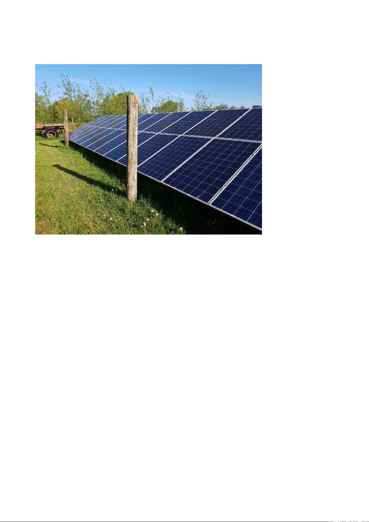
• The third scenario simulations a situation where a small shadow moves over the panels
during the day. Therefore, a pole of 1,2 m high and 20 cm diameter is placed in a distance
of 30 cm from the PV panels in the middle of each PV- string as shown in Figure 12. Over
the day the shadow of the pole moves over the panels in the morning and in the evening
shading up to 4 modules, while at noon only one module is shaded. This example simulates
partial shading coming from nearby objects such as a chimney or dormer affecting a portion
of the PV-array during the typical day. (Chapter 2.3)
THE IMPACT OF OPTIMIZERS FOR PV-MODULES
6
SMA SB3.6-1AV-40
+ Tigo TS4-R-O MLPE
SolarEdge SE HD Wave 3,6
+ P300 MLPE
98,8%
and 98,8%
combined total 97,6%
1.6 The Test setup
1.6.1 The Test Site
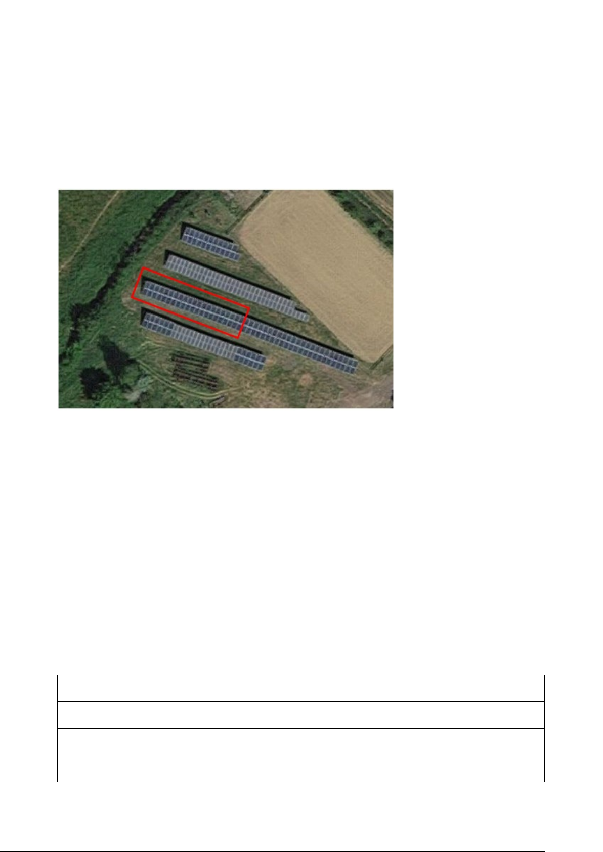
The test site is a small ground mounted PV field in southern Denmark. It consists of 42 identical PV
modules with an orientation to south-south-west (201 degree) (Figure 4).
Figure 4 Satellite picture of test site (Source: google maps)
The tilt is fixed to 42 degree.
The 42 panels in the red box in Figure 4 are connected in three strings. The first 14 panels from
the left (seven of the lower row, seven of the upper row) are equipped with an open optimizer system (MLPE system A) that can be connected to nearly any inverter. These optimizers are connected to each PV module. The 14 panels in the middle feed their energy through a proprietary optimizer system (MLPE system B). Also, here MLPEs are installed to each PV-Module, but in contrast to an open system, a dedicated inverter is needed. The 14 panels most right in the red box
are directly connected to a modern string inverter with advanced MPP-tracking.
1.6.2 PV inverter system selection
To achieve comparable results similar power ratings for all three inverter systems have been chosen. For the reference system without MLPEs a modern string inverter with advanced MPPT from
SMA is chosen. For the MLPE system A optimizers from Tigo and the same inverter as for the reference system is selected. In that way the impact of the optimizers on the overall performance can
be easily investigated. For the MLPE system B an inverter-optimizer system from SolarEdge is
chosen. Table 1 shows which components are applied for the different inverter systems.
Table 1: Components for the different PV inverter systems
PV-Inverter System Components EU-Efficiency
Modern String Inverter SMA SB3.6-1AV-40 96,5%
MLPE System A
MLPE System B
96,5%
x MLPE efficiency
inverter
inverter
MLPE

THE IMPACT OF OPTIMIZERS FOR PV-MODULES
7
Since the aim of this study is not to compare DC to AC conversion efficiency of inverters, but the
impact of optimizers on the overall energy production, only the real measured data are considered
for this study. However, the reader should keep in mind that future generations of string inverters
with higher efficiency will further increase the energy yield compared to systems equipped with optimizers.
1.7 Data Acquisition
The energy production is recorded by measuring current and voltage at the grid side of the inverters every 5 seconds. For the data recording the WattsOn Universal Power Transducer from
ELKOR is applied. The absolute accuracy of the power reading is specified by 0.2%. However, for
this investigation the deviation between each channel is most relevant. Therefore, pre-test have
been conducted where all channels have measured the same current and same voltage. The output reading was exactly the same for all channels and thereby allowing a fair comparison of the
three different systems.
Over the course of the year it occurs that some test arrays are unevenly shaded from nearby trees
after 5:22 pm. To ensure that this has no bias on the results, comparative measurements are only
taken until 5:22 pm each day.
 Loading...