

Page 1

Operating
Instructions
Prüfvorrichtung /i
Richtvorrichtung /i
Testing system /i
Straightening system /i
Dispositif d essai /i
Dispositif de réglage /i
Kontrollinnretning /i
Justeringsinnretning /i
DE
EN-US
FR
NO
Bedienungsanleitung
Operating instructions
Instructions de service
Bruksanvisning
42,0410,2374 008-15062022
Page 2

Page 3

Inhaltsverzeichnis
Allgemeine Informationen 5
Allgemeines 7
Sicherheit 7
Allgemeines 7
Prüfvorrichtung kalibrieren 7
Benötigtes Werkzeug 8
Hinweis zum Prüfen und Einrichten 8
Optionen 8
Lieferumfang 9
Prüf- / Richtvorrichtung /i 9
Lieferumfang Prüfvorrichtung /i G/W System 9
Lieferumfang Prüfvorrichtung /i G/W V 10
Fixierset /i G/W TX 10
Richtvorrichtung /i 11
MTB R Roboter-Schweißbrenner prüfen 13
MTB R Roboter-Schweißbrenner mit Prüf- / Richtvorrichtung /i prüfen 15
Prüfeinheit vorbereiten 15
Brennerkörper für das Prüfen vorbereiten 16
Brennerkörper prüfen 17
MTB R Roboter-Schweißbrenner Gesamtsysteme mit Prüfvorrichtung /i G/W System prüfen 18
Allgemeines 18
Prüfvorrichtung /i G/W System und Brennerkörper des Gesamtsystems vorbereiten 18
Prüfvorrichtung /i G/W System justieren 19
Gesamtsystem prüfen 20
Kundenspezifische Roboter-Schweißbrenner mit Prüfvorrichtung /i G/W V prüfen 22
Allgemeines 22
Prüfvorrichtung /i G/W V und Brennerkörper vorbereiten 22
Prüfvorrichtung /i G/W V justieren 24
Kundenspezifische Roboter-Schweißbrenner prüfen 25
TX Roboter-Schweißbrenner mit Fixierset /i G/W TX prüfen 26
Allgemeines 26
Prüfeinheit und Brennerkörper vorbereiten 26
Fixierset /i G/W TX und TX Roboter-Schweißbrenner auf der Brennerkörper-Aufnahme
montieren
26
DE
MTB R Roboter-Schweißbrenner einrichten 29
Roboter-Schweißbrenner einrichten 31
Brennerkörper für das Einrichten vorbereiten 31
Brennerkörper einrichten 32
Abschließende Tätigkeiten 34
Kundenspezifische Roboter-Schweißbrenner mit Prüfvorrichtung /i G/W V einrichten 35
Allgemeines 35
Brennerkörper für das Einrichten vorbereiten 35
Prüfvorrichtung /i G/W V vorbereiten 36
Brennerkörper-Aufnahme montieren 36
Prüfeinheit montieren 37
Kundenspezifische Roboter-Schweißbrenner einrichten 37
3
Page 4

4
Page 5

Allgemeine Informationen
5
Page 6

6
Page 7

Allgemeines
DE
Sicherheit
Gefahr durch Fehlbedienung und fehlerhaft durchgeführte Arbeiten.
Schwerwiegende Personen- und Sachschäden können die Folge sein.
▶
▶
▶
Allgemeines Prüfvorrichtung /i
Die Prüfvorrichtung /i dient zum Überprüfen von MTB R Roboter-Schweißbrennern auf Maßabweichungen.
Die Prüfvorrichtung /i ist in folgenden Ausführungen verfügbar:
WARNUNG!
Alle in diesem Dokument beschriebenen Arbeiten und Funktionen dürfen
nur von geschultem Fachpersonal ausgeführt werden.
Dieses Dokument lesen und verstehen.
Sämtliche Bedienungsanleitungen der Systemkomponenten, insbesondere
Sicherheitsvorschriften lesen und verstehen.
Prüf-/Richtvorrichtung /i
44,0360,0073
zum Überprüfen von gas- und wassergekühlten MTB R Roboter-Schweißbrennern
Prüfvorrichtung /i G/W System
44,0360,0090
zum Überprüfen von gesamten Roboter-Schweißbrenner-Systemen (z.B.:
Schweißbrenner mit Roboter-Schlauchpaket, Halteschelle und Abschaltbox)
Prüfvorrichtung
kalibrieren
Prüfvorrichtung /i G/W V
44,0360,0012
zum Überprüfen von gas- und wassergekühlten kundenspezifischen RoboterSchweißbrennern und Sonderanfertigungen
Richtvorrichtung /i
44,0350,5241
Mit Hilfe der Richtvorrichtung /i können Maßabweichungen an MTB R RoboterSchweißbrennern korrigiert werden.
WICHTIG! Bei Maßabweichungen > 5 mm den Brennerkörper nicht mehr selbst
einrichten! Brennerkörper zur Reparatur an Fronius einsenden.
WICHTIG! Um mit der Prüfvorrichtung /i optimale Prüfergebnisse zu erreichen,
empfiehlt es sich, die Prüfvorrichtung jährlich bei Fronius kalibrieren zu lassen.
7
Page 8

Benötigtes
Werkzeug
Innensechskant-Schlüssel SW 6 mm
-
Kontaktrohr-Schlüssel
-
42,0410,0570 ... M6
42,0410,0138 ... M8x1,5
Brennerschlüssel
-
45,0200,1261
Drehmomentschlüssel
-
42,0435,0090
Hinweis zum
Prüfen und Einrichten
Optionen
HINWEIS!
Für das Prüfen und das Einrichten von Brennerkörpern nach Möglichkeit zwei
verschiedene Grundplatten verwenden, beispielsweise:
Prüfen mit Prüfvorrichtung /i
▶
Einrichten auf der Grundplatte Stahl „Professional“
▶
Grundplatte Stahl „Professional“ (42,0201,2064)
-
z.B. für häufige Prüf- und Richtarbeiten (nur Werkseinbau)
Fixierset /i G/W TX (44,0350,5242)
-
zum Überprüfen von gas- und wassergekühlten TX Roboter-Schweißbrennern
8
Page 9

Lieferumfang
(1)
(2)
(3)
(4)
(5)
(6)
(7)
(8)
(1)
(2)
(3)
(4)
(5)
(6)
(7)
(10)
(8)
(9)
(14)
(13)
(12)
(11)
Prüf- / Richtvorrichtung /i
DE
Lieferumfang
Prüfvorrichtung /i G/W System
(1) Brennerkörper-Aufnahme
(2) Zentrierhülse M6
(3) Zentrierhülse M8
(4) Zentrierhülse M8x1,5
(5) Zentrierhülse M10x1,25
(6) Zentrierhülse M10x1,25 Con-
tec
(7) Grundplatte Alu
(8) Prüfeinheit
(1) Aufnahmeblock
(2) 4 Spanneisen mit Schrauben
(3) Grundplatte Alu
(4) Einstellhülse M10x1,25 Con-
tec
(5) Einstellhülse M10x1,25
(6) Einstellhülse M8x1,5
(7) Einstellhülse M8
(8) Einstellhülse M6
(9) Zentrierhülse M6
(10) Prüfeinheit
(11) Zentrierhülse M8
(12) Zentrierhülse M8x1,5
(13) Zentrierhülse M10x1,25
(14) Zentrierhülse M10x1,25 Con-
tec
9
Page 10

Lieferumfang
(1)
(2)
(3)
(4)
(5)
(6)
(7)
(14)
(13)
(12)
(11)
(10)
(8)
(9)
(1) (2)(3)
(2)
*
**
Prüfvorrichtung /i G/W V
Fixierset /i G/W
TX
(1) Brennerkörper-Aufnahme
(2) 4 Spanneisen mit Schrauben
(3) Grundplatte Alu
(4) Einstellhülse M10x1,25 Con-
tec
(5) Einstellhülse M10x1,25
(6) Einstellhülse M8x1,5
(7) Einstellhülse M8
(8) Einstellhülse M6
(9) Zentrierhülse M6
(10) Prüfeinheit
(11) Zentrierhülse M8
(12) Zentrierhülse M8x1,5
(13) Zentrierhülse M10x1,25
(14) Zentrierhülse M10x1,25 Con-
tec
(1) Spannbuchse
(2) 2 Pass-Schulterschrauben 6h8
M5 x 20 mm
(3) Spannbügel
* Brennerkörper
** Brennerkörper-Aufnahme
(im Lieferumfang der Prüfvorrichtung enthalten)
10
Page 11

Richtvorrich-
(1)
(2)
(3)
(4)
(5)
tung /i
Richtvorrichtung /i - 44,0350,5241
(1) Richthebel
(2) Drehmomentschlüssel
(3) Überwurfmutter
(4) Brennerschlüssel
(5) Richtschale ø 16 mm
Richtschale ø 18 mm
DE
11
Page 12

12
Page 13

MTB R Roboter-Schweißbrenner
prüfen
13
Page 14

14
Page 15

MTB R Roboter-Schweißbrenner mit Prüf- /
Richtvorrichtung /i prüfen
Prüfeinheit vorbereiten
Bezeichnung Länge (mm) Länge (inch) Höhe (mm) Höhe (inch) Winkel
A 0° 250 9.842 0 0 0°
DE
Auf der Grundplatte der Prüfvorrichtung /i befinden sich verschiedenste
Positionen zur Montage der Prüfeinheit.
Im Auslieferungszustand ist die
Prüfeinheit auf die Montageposition 0°
vormontiert.
Für jede andere BrennerkörperKrümmung die Prüfeinheit entsprechend der Brennerkörper-Krümmung
des zu prüfenden Schweißbrenners auf
der Grundplatte montieren:
A 22° 241 9.488 50 1.969 22°
A 36° 224 8.819 86 3.386 36°
A 45° 209 8.228 107 4.213 45°
A1 0° 187,5 7.382 0 0 0°
A2 22° 246 9.685 27 1.063 22°
A2 45° 228,5 8.996 56,5 2.224 45°
A2 60° 212 8.346 71 2.795 60°
A3 36° 236 9.291 44,5 1.752 36°
B 0° 335 13.189 0 0 0°
B 22° 331 13.032 27 1.063 22°
B 45° 313,5 12.342 56,5 2.224 45°
B 60° 297 11.692 71 2.795 60°
B1 22° 291 11.457 50 1.969 22°
B2 22° 325 12.795 50 1.969 22°
B3 36° 338 13.307 0 0 36°
B4 36° 321 12.638 44,5 1.752 36°
C 22° 383 15.079 50 1.969 22°
C 36° 366 14.409 86 3.386 36°
C 45° 351 13.819 105 4.134 45°
15
Page 16

1
2
1
2
1
2
1
(1)
(2)
(3)
(4)
(5)
1
1
2
2
Brennerkörper
für das Prüfen
vorbereiten
1
3
2
(1) ... M6 (2) ... M8 (3) ... M8x1,5 (4) ... M10x1,25
(5) ... M10x1,25 Contec
16
Page 17
Brennerkörper
1
2
1
prüfen
1
HINWEIS!
Der Brennerkörper ist in Ordnung, wenn
der Pass-Stift leichtgängig und vollständig in die Zentrierhülse gleitet, und
▶
der Pass-Stift nach Loslassen der Feder auf Grund der Federkraft wieder
▶
leichtgängig aus der Zentrierhülse heraus gleitet.
2
DE
Lässt sich der Pass-Stift nicht leichtgängig in die oder aus der Zentrierhülse bewegen, den Brennerkörper gemäß Kapitel „MTB R Roboter-Schweißbrenner einrichten“ einrichten (ab Seite 29).
WICHTIG! Bei Maßabweichungen > 5 mm den Brennerkörper nicht mehr selbst
einrichten! Brennerkörper zur Reparatur an Fronius einsenden.
17
Page 18

MTB R Roboter-Schweißbrenner Gesamtsysteme
1
2
2
1
mit Prüfvorrichtung /i G/W System prüfen
Allgemeines Mit Hilfe der Prüfvorrichtung /i G/W System lassen sich komplette Roboter-
Schweißbrenner-Systeme vom Brennerkörper bis zur CrashBox auf Maßabweichungen überprüfen.
Für Aufbau und Erstjustierung ist der Anwender verantwortlich.
Zur Überprüfung stehen verschiedene Möglichkeiten zur Verfügung, z.B.:
Brennerkörper
-
Brennerkörper + Schlauchpaket
-
Brennerkörper + Schlauchpaket + Halteschelle
-
Brennerkörper + Schlauchpaket + Halteschelle + CrashBox
-
Prüfvorrichtung /i G/W System und Brennerkörper des
Gesamtsystems
vorbereiten
Brennerkörper des Gesamtsystems mittels geeigneter Prüfvorrichtung
1
prüfen
Auf der Grundplatte der Prüfvorrichtung /i G/W System befinden sich verschiedenste Positionen zur Montage der Prüfeinheit.
Im Auslieferungszustand ist die Prüfeinheit auf die Montageposition 0° vormontiert.
Für jede andere Brennerkörper-Krümmung die Prüfeinheit entsprechend der
Brennerkörper-Krümmung des zu prüfenden Schweißbrenners auf der Grundplatte montieren:
2
3
18
HINWEIS!
Zur Unterscheidung von Zentrierhülsen (2) und Einstellhülsen (1) sind Einstellhülsen mit zwei zusätzlichen Querrillen ausgestattet.
Page 19

(1)
(2)
1
4
1
1
min 15mm
min 0.59inch
1
1
1
1
2
1
Einstellhülse abschrauben
5
Der Aufnahmeblock ist zur Montage unterschiedlicher Roboter-Abschaltboxen
vorgesehen.
6
DE
Prüfvorrichtung /i G/W System justieren
Gesamtsystem auf Aufnahmeblock montieren
1
2
19
Page 20

1
3
1
1
3
2
2
1
Der Pass-Stift muss leichtgängig und
vollständig in die Einstellhülse gleiten.
Der Pass-Stift muss nach Loslassen
der Feder auf Grund der Federkraft
wieder leichtgängig aus der Einstellhülse heraus gleiten.
Lässt sich der Pass-Stift nicht oder nur
schwergängig in die Einstellhülse einschieben, Gesamtsystem mit Aufnahmeblock nachjustieren.
Gesamtsystem
prüfen
4
5
Lässt sich der Pass-Stift nicht oder nur schwergängig in die Einstellhülse einschieben, Gesamtsystem mit Aufnahmeblock nachjustieren.
HINWEIS!
Das Schlauchpaket muss während der Prüfung entlastet sein.
Bei nicht entlastetem Schlauchpaket kann eine Fehlstellung der Roboter-Abschaltbox auftreten.
HINWEIS!
Zur Unterscheidung von Zentrierhülsen (2) und Einstellhülsen (1) sind Einstellhülsen mit zwei zusätzlichen Querrillen ausgestattet.
20
Page 21

2
1
1
(1)
(2)
1
1
1
1
2
DE
Zentrierhülse abschrauben
3
4
Gesamtsystem auf Aufnahmeblock montieren
5
HINWEIS!
Das Gesamtsystem ist in Ordnung, wenn
der Pass-Stift leichtgängig und vollständig in die Zentrierhülse gleitet, und
▶
der Pass-Stift nach Loslassen der Feder auf Grund der Federkraft wieder
▶
leichtgängig aus der Zentrierhülse heraus gleitet.
Lässt sich der Pass-Stift nicht leichtgängig in die oder aus der Zentrierhülse bewegen, Gesamtsystem einrichten (z.B. an der Halteschelle).
21
Page 22

Kundenspezifische Roboter-Schweißbrenner mit
1
2
2
1
Prüfvorrichtung /i G/W V prüfen
Allgemeines Mit Hilfe der Prüfvorrichtung /i G/W V lassen sich kundenspezifische Roboter-
Schweißbrenner und Sonderanfertigungen auf Maßabweichungen überprüfen.
Für Aufbau und Erstjustierung ist der Anwender verantwortlich.
Prüfvorrichtung /i G/W V
und Brennerkörper vorbereiten
Auf der Grundplatte der Prüfvorrichtung /i G/W V befinden sich verschiedenste Positionen zur Montage der
Prüfeinheit.
Im Auslieferungszustand ist die
Prüfeinheit auf die Montageposition 0°
vormontiert.
Für jede andere BrennerkörperKrümmung die Prüfeinheit entsprechend der Brennerkörper-Krümmung
des zu prüfenden Schweißbrenners auf
der Grundplatte montieren:
1
2
22
Page 23

2
1
3
(1)
(2)
1
1
1
2
HINWEIS!
Zur Unterscheidung von Zentrierhülsen (2) und Einstellhülsen (1) sind Einstellhülsen mit zwei zusätzlichen Querrillen ausgestattet.
DE
4
Einstellhülse abschrauben
6
5
23
Page 24

Prüfvorrich-
min 15mm
min 0.59inch
1
1
1
1
1
3
2
3
1
1
3
2
2
3
tung /i G/W V
justieren
1
2
3
Der Pass-Stift muss leichtgängig und
vollständig in die Einstellhülse gleiten.
Der Pass-Stift muss nach Loslassen
der Feder auf Grund der Federkraft
wieder leichtgängig aus der Einstellhülse heraus gleiten.
Lässt sich der Pass-Stift nicht oder nur
schwergängig in die Einstellhülse einschieben, Brennerkörper-Aufnahme
mit Brennerkörper nachjustieren.
4
5
24
Lässt sich der Pass-Stift nicht oder nur schwergängig in die Einstellhülse einschieben, Brennerkörper-Aufnahme mit Brennerkörper nachjustieren.
Page 25

Kundenspezifi-
2
1
(1)
(2)
1
1
sche RoboterSchweißbrenner
prüfen
1
HINWEIS!
Zur Unterscheidung von Zentrierhülsen (2) und Einstellhülsen (1) sind Einstellhülsen mit zwei zusätzlichen Querrillen ausgestattet.
DE
2
Zentrierhülse abschrauben
3
25
Page 26

TX Roboter-Schweißbrenner mit Fixierset /i G/W
1
2
1
TX prüfen
Allgemeines Das Fixierset /i G/W TX ist eine Erweiterung zum Überprüfen von TX Roboter-
Schweißbrennern und wird in Verbindung mit folgenden Prüfvorrichtungen eingesetzt:
Prüf-/Richtvorrichtung /i (44,0360,0073)
-
Prüfvorrichtung /i G/W V (44,0360,0012)
-
Die Prüfeinheiten werden wie beschrieben aufgebaut.
Anschließend werden Fixierset /i G/W TX und der TX Roboter-Schweißbrenner
auf der Brennerkörper-Aufnahme montiert.
Der Prüfvorgang erfolgt dann entsprechend der jeweiligen Prüfvorrichtung.
Prüfeinheit und
Brennerkörper
vorbereiten
Fixierset /i G/W
TX und TX RoboterSchweißbrenner
auf der Brennerkörper-Aufnahme montieren
Prüf-/Richtvorrichtung /i
44,0360,0073
siehe Seite 15
siehe Seite 16
1
Prüfvorrichtung /i G/W V
44,0360,0012
siehe Seite 22
2
26
Page 27

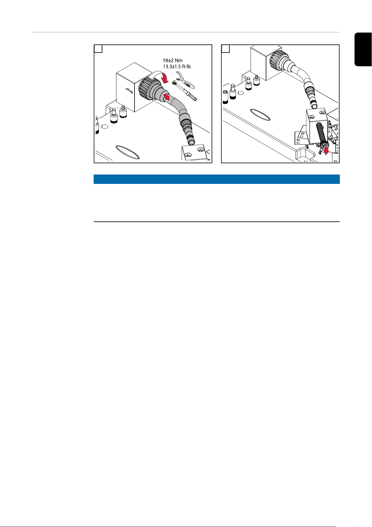
1
1
3
1
1
1
1
0
18
13.3
+
2Nm
-
1.5 ft·lb
+
-
4
DE
5
Drehmomentschlüssel verwenden!
27
Page 28

28
Page 29

MTB R Roboter-Schweißbrenner
einrichten
29
Page 30

30
Page 31

Roboter-Schweißbrenner einrichten
2
1
1
2
3
(1)
(2)
(3)
1
2
3
4
(1)
(2)
(3)
(4)
(5)
1
1
2
DE
Brennerkörper
für das Einrichten vorbereiten
1
3
2
4
Düsenstock-Ersatz und Richthülse einschrauben
5
Zentrierhülse einschrauben
Zentrierhülse abschrauben
(1) ... M6 (2) ... M8 (3) ... M8x1,5 (4) ... M10x1,25
(5) ... M10x1,25 Contec
31
Page 32

Brennerkörper
1
2
2
1
1
*
1
1
einrichten
Vorbereitung:
1
3
2
* Die Richtschalen sind nur für das Einrichten
am Außenrohr erforderlich.
4
32
Für das Einrichten am Außenrohr den Richthebel über die Richtschalen schieben
Richthebel über der Richthülse positionieren
Brennerkörper horizontal und / oder vertikal einrichten:
5
Horizontal Einrichten
6
Vertikal Einrichten
Page 33

2
1
7
1
8
DE
Überwurfmutter lösen und wieder festziehen
HINWEIS!
Der Brennerkörper ist in Ordnung, wenn
der Pass-Stift leichtgängig und vollständig in die Zentrierhülse gleitet, und
▶
der Pass-Stift nach Loslassen der Feder auf Grund der Federkraft wieder
▶
leichtgängig aus der Zentrierhülse heraus gleitet.
Lässt sich der Pass-Stift nicht leichtgängig in die oder aus der Zentrierhülse bewegen, den Brennerkörper erneut einrichten.
WICHTIG! Bei Maßabweichungen > 5 mm den Brennerkörper nicht mehr selbst
einrichten! Brennerkörper zur Reparatur an Fronius einsenden.
Brennerkörper prüfen
33
Page 34

Abschließende
Tätigkeiten
Ist der Brennerkörper in Ordnung:
Richthebel abnehmen
1
Überwurfmutter lösen
2
Brennerkörper von der Prüfvorrichtung abnehemen
3
Richthülse vom Brennerkörper abschrauben
4
Zentrierhülse vom Brennerkörper abschrauben
5
Düsenstock-Ersatz abnehmen
6
Verschleißteile entsprechend der Bedienungsanleitung des Schweißbrenners
7
am Brennerkörper montieren
34
Page 35

Kundenspezifische Roboter-Schweißbrenner mit
2
1
1
2
3
(1)
(2)
(3)
1
2
3
4
1
*
Prüfvorrichtung /i G/W V einrichten
Allgemeines Die Prüfvorrichtung /i G/W V ist auch zum Einrichten von kundenspezifischen
Schweißbrennern ausgelegt.
Brennerkörper
für das Einrichten vorbereiten
1
2
DE
3
Düsenstock-Ersatz und Richthülse einschrauben
4
Zentrierhülse abschrauben
* Brennerkörper-Aufnahme ausgeblendet
35
Page 36

1
2
5
4
1
1
2
4
4
3
3
3
5
180°
1
3
2
2
2
2
4x
Zentrierhülse einschrauben
Prüfvorrichtung /i G/W V
vorbereiten
BrennerkörperAufnahme montieren
1
1
36
Page 37

Prüfeinheit mon-
2
3
min 15mm
min 0.59inch
1
1
1
1
1
3
5
4
6
2
1
1
tieren
1
2
DE
Kundenspezifische RoboterSchweißbrenner
einrichten
Prüfeinheit zum Brennerkörper ausrichten und
mit einem Spanneisen leicht fixieren
3
Prüfeinheit mit den restlichen Spanneisen fixieren
Brennerkörper prüfen
4
Brennerkörper prüfen
HINWEIS!
Für das Einrichten des Schweißbrenners muss
die Brennerkörper-Aufnahme mit 4 Schrauben im Bereich der Einstell-/
▶
Zentrierhülsen auf der Prüfvorrichtung /i G/W V montiert sein,
der Schweißbrenner an der Brennerkörper-Aufnahme montiert sein.
▶
Schweißbrenner einrichten
1
Das Einrichten des Schweißbrenners funktioniert wie unter „Brennerkörper
einrichten“ ab Seite 32 beschrieben:
Einrichten am Außenrohr mit den Richtschalen
-
Einrichten am Brennerkörper-Ende mittels Richthülse
-
Horizontales / vertikales Einrichten
-
Abschließende Tätigkeiten gemäß Seite 34 durchführen
2
37
Page 38

38
Page 39

Table of contents
General information 41
General 43
Safety 43
General 43
Calibrating the Testing System 43
Required Tools 44
Notes for Testing and Setup 44
Options 44
Scope of Supply 45
Testing / Straightening System /i 45
Scope of Delivery, Testing System /i G/W System 45
Scope of Delivery, Testing System /i G/W V 46
Fixing Set /i G/W TX 46
Straightening System /i 47
Check MTB R robot welding torch 49
Check MTB R robot welding torch with testing / straightening system /i 51
Preparing the testing unit 51
Preparing the torch body for testing 52
Checking the torch body 53
Check MTB R robot welding torch complete systems with testing system /i G/W System 54
General 54
Preparing the Testing System /i G/W System and Torch Body of the Complete System 54
Calibrating the Testing System /i G/W System 55
Checking the Complete System 56
Check customer-specific robot welding torch with testing system /i G/W 59
General 59
Preparing the testing system /i G/W V and torch body 59
Calibrating the Testing System /i G/W V 61
Checking the Customer-Specific Robot Welding Torches 62
Check TX robot welding torches with fixing system /i G/W TX 63
General 63
Preparing the Testing Unit and Torch Body 63
Mounting the fixing set /i G/W TX and TX robot welding torch onto the torch body holder 63
EN-US
Set up MTB R robot welding torch 65
Set up robot welding torch 67
Preparing the Torch Body for Setup 67
Setting up the torch body 68
Final tasks 70
Set up customer-specific robot welding torch with testing system /i G/W V 71
General 71
Preparing the Torch Body for Setup 71
Preparing the Testing System /i G/W V 72
Mounting the Torch Body Holder 72
Mounting the Testing Unit 73
Setting up Customer-Specific Robot Welding Torch 73
39
Page 40

40
Page 41

General information
41
Page 42

42
Page 43

General
Safety
Danger from incorrect operation and work that is not carried out properly.
Serious injury and damage to property may result.
▶
▶
▶
General Testing system /i
The testing system /i is used to check MTB R robot welding torches for dimensional deviations.
The testing system /i is available in the following configurations:
WARNING!
All the work and functions described in this document must only be carried
out by trained and qualified personnel.
Read and understand this document.
Read and understand all the Operating Instructions for the system components, especially the safety rules.
Testing/straightening system
44,0360,0073
for checking gas and water-cooled MTB R robot welding torches
Testing system /i G/W system
44,0360,0090
for checking complete robot welding torch systems (e.g.: welding torch with robot hose pack, clamp and shutoff box)
EN-US
Calibrating the
Testing System
Testing system /i G/W V
44,0360,0012
for checking gas and water-cooled, customer-specific robot welding torches
and special models
Straightening system /i
44,0350,5241
With the straightening system /i dimensional deviations can be corrected on the
MTB R robot welding torches.
IMPORTANT! For dimensional deviations > 5 mm, you should no longer set up
the torch body on your own. Send torch body to Fronius for repair.
IMPORTANT! In order to achieve optimal test results with the testing system /i,
it is recommended that the system be calibrated by Fronius on a yearly basis.
43
Page 44

Required Tools
Allen key size 6 mm
-
Contact-tip spanner
-
42,0410,0570 ... M6
42,0410,0138 ... M8x1.5
Torch wrench
-
45,0200,1261
Torque wrench
-
42,0435,0090
Notes for Testing
and Setup
Options
NOTE!
If possible, use two different base plates for checking and setting up the torch
bodies, for example:
Checking with testing system /i
▶
Set up on steel “professional” base plate
▶
Steel “professional” base plate (42,0201,2064)
-
e.g. for frequent testing and straightening work (only factory installation)
Test shaft (xx,xxxx,xxxx)
-
for checking of the testing system /i
Fixing set /i G/W TX (44,0350,5242)
-
for checking of gas and water-cooled TX robot welding torches
44
Page 45

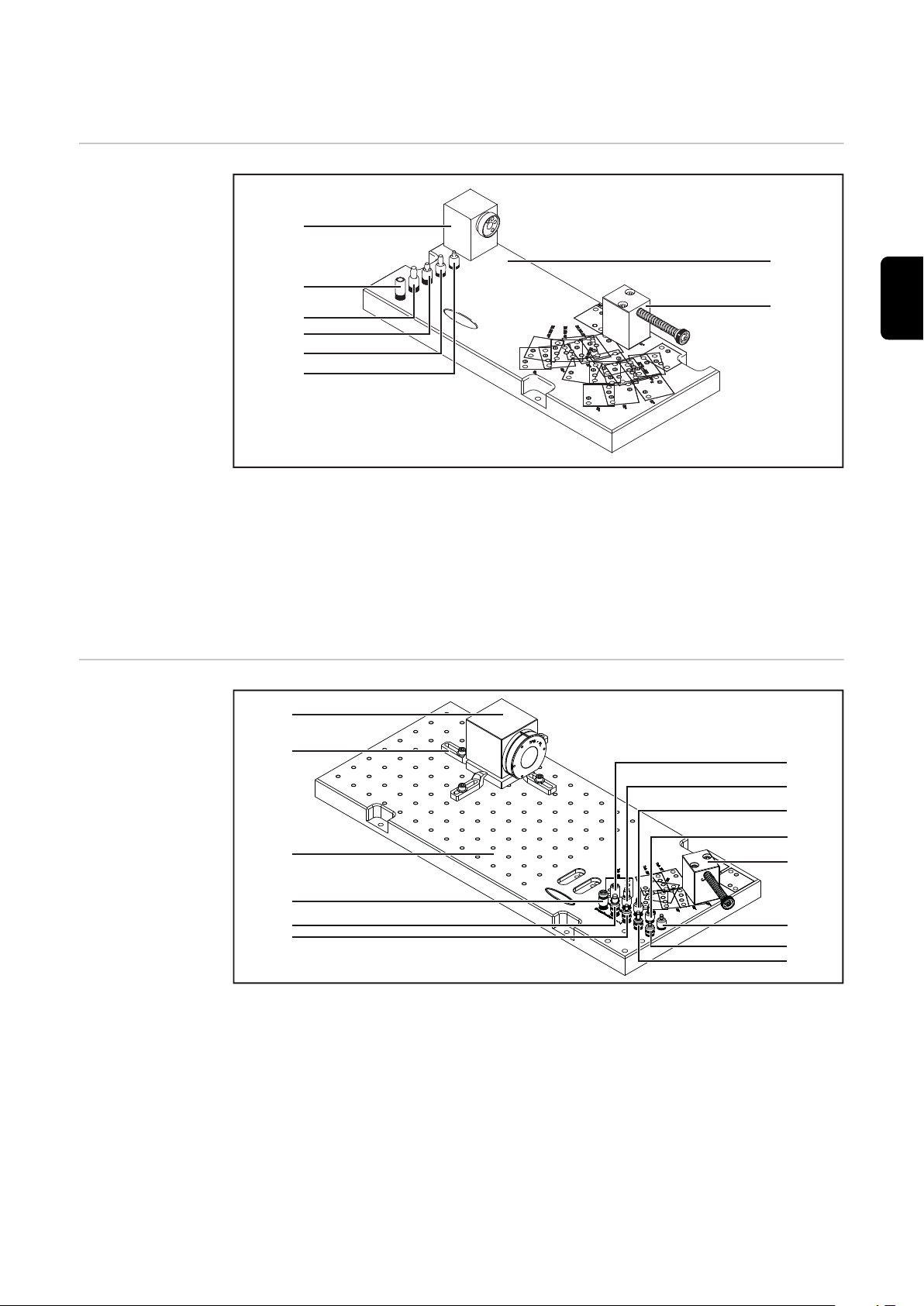
Scope of Supply
(1)
(2)
(3)
(4)
(5)
(6)
(7)
(8)
(1)
(2)
(3)
(4)
(5)
(6)
(7)
(10)
(8)
(9)
(14)
(13)
(12)
(11)
Testing / Straightening System /i
EN-US
Scope of Delivery, Testing
System /i G/W
System
(1) Torch body holder
(2) Centering sleeve M6
(3) Centering sleeve M8
(4) Centering sleeve M8x1.5
(5) Centering sleeve M10x1.25
(6) Centering sleeve M10x1.25
Contec
(7) Base plate aluminum
(8) Testing unit
(1) Mounting block
(2) 4 clamps with screws
(3) Base plate aluminum
(4) Adjusting sleeve M10x1.25
Contec
(5) Adjusting sleeve M10x1.25
(6) Adjusting sleeve M8x1.5
(7) Adjusting sleeve M8
(8) Adjusting sleeve M6
(9) Centering sleeve M6
(10) Testing unit
(11) Centering sleeve M8
(12) Centering sleeve M8x1.5
(13) Centering sleeve M10x1.25
(14) Centering sleeve M10x1.25
Contec
45
Page 46

Scope of Deli-
(1)
(2)
(3)
(4)
(5)
(6)
(7)
(14)
(13)
(12)
(11)
(10)
(8)
(9)
(1) (2)(3)
(2)
*
**
very, Testing
System /i G/W V
Fixing Set /i G/W
TX
(1) Torch body holder
(2) 4 clamps with screws
(3) Base plate aluminum
(4) Adjusting sleeve M10x1.25
Contec
(5) Adjusting sleeve M10x1.25
(6) Adjusting sleeve M8x1.5
(7) Adjusting sleeve M8
(8) Adjusting sleeve M6
(9) Centering sleeve M6
(10) Testing unit
(11) Centering sleeve M8
(12) Centering sleeve M8x1.5
(13) Centering sleeve M10x1.25
(14) Centering sleeve M10x1.25
Contec
(1) Clamping bush
(2) 2 shoulder bolts 6h8
M5 x 20 mm
(3) Clamp
* Torch body
** Torch body holder
(included in the scope of delivery of the testing system)
46
Page 47

Straightening
(1)
(2)
(3)
(4)
(5)
System /i
Straightening system /i - 44,0350,5241
(1) Straightening lever
(2) Torque wrench
(3) Union nut
(4) Torch wrench
(5) Straightening cup ø 16 mm
Straightening cup ø 18 mm
EN-US
47
Page 48

48
Page 49

Check MTB R robot welding torch
49
Page 50

50
Page 51

Check MTB R robot welding torch with testing /
straightening system /i
Preparing the
testing unit
The base plate of the testing system /i
contains various positions for mounting the testing unit.
The testing unit is pre-mounted on the
0° mounting position when delivered.
For every other torch body curvature,
the testing unit must be mounted on
the base plate according to the torch
body curvature of the welding torch
that is to be tested:
Name Length
(mm)
A 0° 250 9.842 0 0 0°
A 22° 241 9.488 50 1.969 22°
A 36° 224 8.819 86 3.386 36°
Length
(inch)
Height
(mm)
Height
(inch)
Angle
EN-US
A 45° 209 8.228 107 4.213 45°
A1 0° 187.5 7.382 0 0 0°
A2 22° 246 9.685 27 1.063 22°
A2 45° 228.5 8.996 56.5 2.224 45°
A2 60° 212 8.346 71 2.795 60°
A3 36° 236 9.291 44.5 1.752 36°
B 0° 335 13.189 0 0 0°
B 22° 331 13.032 27 1.063 22°
B 45° 313.5 12.342 56.5 2.224 45°
B 60° 297 11.692 71 2.795 60°
B1 22° 291 11.457 50 1.969 22°
B2 22° 325 12.795 50 1.969 22°
B3 36° 338 13.307 0 0 36°
B4 36° 321 12.638 44.5 1.752 36°
C 22° 383 15.079 50 1.969 22°
C 36° 366 14.409 86 3.386 36°
C 45° 351 13.819 105 4.134 45°
51
Page 52
1
2
1
2
1
2
1
(1)
(2)
(3)
(4)
(5)
1
1
2
2
Preparing the
torch body for
testing
1
3
2
(1) ... M6 (2) ... M8 (3) ... M8x1.5 (4) ... M10x1.25
(5) ... M10x1.25 Contec
52
Page 53

Checking the
1
2
1
torch body
1
NOTE!
The torch body is okay if
The dowel pin glides fully into the centering sleeve with ease
▶
The dowel pin glides out of the centering sleeve with ease after the spring is
▶
released due to the spring force
2
EN-US
If the dowel pin cannot easily be moved into or out of the centering sleeve, set
up the torch body according to the chapter "Set up MTB R robot welding torch"
(from page 65).
IMPORTANT! For dimensional deviations > 5 mm, you should no longer set up
the torch body on your own. Send torch body to Fronius for repair.
53
Page 54

Check MTB R robot welding torch complete sys-
1
2
2
1
tems with testing system /i G/W System
General With the testing system /i G/W System you can check complete robot welding
torch systems from torch body to CrashBox for dimensional deviations.
The user is responsible for the setup and initial adjustment.
There are various possibilities available for testing, e.g.:
Torch body
-
Torch body + hosepack
-
Torch body + hosepack + clamp
-
Torch body + hosepack + clamp + CrashBox
-
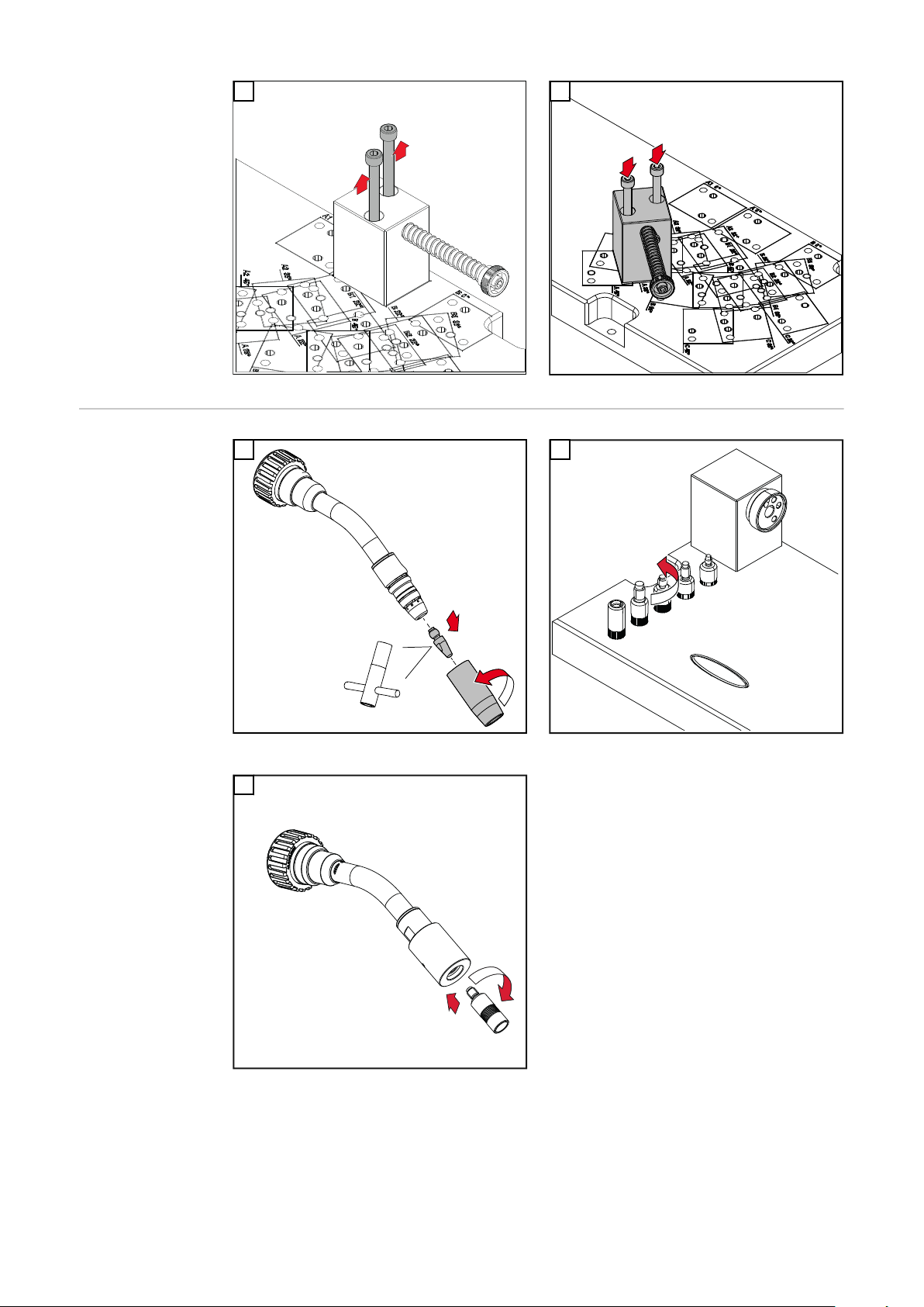
Preparing the
Testing System /i
G/W System and
Torch Body of
the Complete
System
Check torch body of the complete system using a suitable testing system
1
The base plate of the testing system /i G/W contains a wide range of positions for
mounting the testing unit.
The testing unit is pre-mounted on the 0° mounting position when delivered.
For every other torch neck curvature, the testing unit must be mounted on the
base plate according to the torch neck curvature of the welding torch that is to
be tested:
2
3
54
NOTE!
To distinguish between centering sleeve (2) and adjusting sleeve (1), the adjusting sleeves are equipped with two additional cross grooves.
Page 55

(1)
(2)
1
4
1
1
min 15mm
min 0.59inch
1
1
1
1
2
1
Unscrew adjusting sleeve
5
The mounting block is designed for mounting various robot shutoff boxes.
6
EN-US
Calibrating the
Testing System /i
G/W System
Mount the complete system on the mounting block
1
2
55
Page 56

1
3
1
1
3
2
2
1
The dowel pin must fully glide into the
adjusting sleeve with ease.
The dowel pin must glide out of the
adjusting sleeve with ease after the
spring is released due to the spring force.
If the dowel pin doesn’t glide into the
adjusting sleeve or only does so with
difficulty, the complete system with
mounting block must be readjusted.
Checking the
Complete System
4
5
If the dowel pin doesn’t glide into the adjusting sleeve or only does so with difficulty, the complete system with mounting block must be readjusted.
NOTE!
The hosepack must be released during checking.
If the hosepack is not released the robot shut off box may be misaligned.
NOTE!
To distinguish between centering sleeve (2) and adjusting sleeve (1), the adjusting sleeves are equipped with two additional cross grooves.
56
Page 57

2
1
1
(1)
(2)
1
1
1
1
2
EN-US
Unscrew centering sleeve.
3
4
Mount the complete system on the mounting
block
5
NOTE!
The complete system is okay if
the dowel pin glides fully into the centering sleeve with ease, and
▶
the dowel pin glides out of the centering sleeve with ease after the spring is
▶
released due to the spring force.
57
Page 58

If the dowel pin does not easily glide into or out of the centering sleeve, the complete system must be adjusted (e.g. at the clamp).
58
Page 59

Check customer-specific robot welding torch with
1
2
2
1
testing system /i G/W
General With the testing system /i G/W V, you can check customer-specific robot welding
torch systems and special models for dimensional deviations.
The user is responsible for the setup and initial adjustment.
EN-US
Preparing the
testing system /i
G/W V and torch
body
The base plate of the testing system /i
G/W V contains various positions for
mounting the testing unit.
The testing unit is pre-mounted on the
0° mounting position when delivered.
For every other torch body curvature,
the testing unit must be mounted on
the base plate according to the torch
body curvature of the welding torch
that is to be tested:
1
2
59
Page 60

2
1
3
(1)
(2)
1
1
1
2
NOTE!
To distinguish between centering sleeve (2) and adjusting sleeve (1), the adjusting sleeves are equipped with two additional cross grooves.
4
Unscrew adjusting sleeve
6
5
60
Page 61

Calibrating the
min 15mm
min 0.59inch
1
1
1
1
1
3
2
3
1
1
3
2
2
3
Testing System /i
G/W V
1
2
EN-US
3
The dowel pin must fully glide into the
adjusting sleeve with ease.
The dowel pin must glide out of the
adjusting sleeve with ease after the
spring is released due to the spring force.
If the dowel pin doesn’t glide into the
adjusting sleeve or only does so with
difficulty, the torch body holder with
torch body must be readjusted.
4
5
If the dowel pin doesn’t glide into the adjusting sleeve or only does so with difficulty, the torch body holder with torch body must be readjusted.
61
Page 62

Checking the
2
1
(1)
(2)
1
1
Customer-Specific Robot Welding Torches
1
NOTE!
To distinguish between centering sleeve (2) and adjusting sleeve (1), the adjusting sleeves are equipped with two additional cross grooves.
2
Unscrew centering sleeve.
3
62
Page 63

Check TX robot welding torches with fixing sys-
1
2
1
tem /i G/W TX
General The fixing set /i G/W TX is an add-on for checking TX robot welding torches and
is used in conjunction with the following testing systems:
Testing/straightening system /i (44,0360,0073)
-
Testing system /i G/W V (44,0360,0012)
-
Testing units are assembled as described.
Afterwards, the fixing set /i G/W TX and the TX robot welding torch are mounted
on the torch body holder.
The testing process is then carried out according to the respective testing system.
EN-US
Preparing the
Testing Unit and
Torch Body
Mounting the fixing set /i G/W
TX and TX robot
welding torch
onto the torch
body holder
Testing/straightening system /i
44,0360,0073
see page 51
see page 52
1
Testing system /i G/W V
44,0360,0012
see page 59
2
63
Page 64

1
1
3
1
1
1
1
0
18
13.3
+
2Nm
-
1.5 ft·lb
+
-
4
5
Use torque wrench!
64
Page 65

Set up MTB R robot welding torch
65
Page 66

66
Page 67

Set up robot welding torch
2
1
1
2
3
(1)
(2)
(3)
1
2
3
4
(1)
(2)
(3)
(4)
(5)
1
1
2
Preparing the
Torch Body for
Setup
1
2
EN-US
3
4
Screw in nozzle fitting replacement and straightening sleeve
5
Screw in centering sleeve
Unscrew centering sleeve
(1) ... M6 (2) ... M8 (3) ... M8x1.5 (4) ... M10x1.25
(5) ... M10x1.25 Contec
67
Page 68

Setting up the
1
2
2
1
1
*
1
1
torch body
Preparation:
1
3
2
* The straightening cups are only required for
setup at the outer tube.
4
68
To set up at the outer tube, push the straightening lever over the straightening cups
Position straightening lever above straightening
sleeve
Set up torch body horizontally and/or vertically:
5
Set up horizontally
6
Set up vertically
Page 69

2
1
7
1
8
EN-US
Loosen union nut and re-tighten
NOTE!
The torch body is okay if
The dowel pin glides fully into the centering sleeve with ease
▶
The dowel pin glides out of the centering sleeve with ease after the spring is
▶
released due to the spring force
If the dowel pin does not easily glide into or out of the centering sleeve, the torch
body must be readjusted.
IMPORTANT! For dimensional deviations > 5 mm, you should no longer set up
the torch body on your own. Send torch body to Fronius for repair.
Check the torch body
69
Page 70

Final tasks If the torch body is okay:
Remove straightening lever
1
Loosen union nut
2
Remove the torch body from the testing system
3
Unscrew straightening sleeve from the torch body
4
Unscrew centering sleeve from the torch body
5
Remove nozzle fitting replacement
6
Mount wearing parts on the torch body according to the Operating Instruc-
7
tions of the welding torch
70
Page 71

Set up customer-specific robot welding torch
2
1
1
2
3
(1)
(2)
(3)
1
2
3
4
1
*
with testing system /i G/W V
General The testing system /i G/W V is also designed to set up customer-specific welding
torches.
EN-US
Preparing the
Torch Body for
Setup
1
3
2
4
Screw in nozzle fitting replacement and straightening sleeve
Unscrew centering sleeve
* Torch body holder not shown
71
Page 72

1
2
5
4
1
1
2
4
4
3
3
3
5
180°
1
3
2
2
2
2
4x
Screw in centering sleeve
Preparing the
Testing System /i
G/W V
Mounting the
Torch Body Holder
1
1
72
Page 73

Mounting the
2
3
min 15mm
min 0.59inch
1
1
1
1
1
3
5
4
6
2
1
1
Testing Unit
1
2
EN-US
Setting up Customer-Specific
Robot Welding
Torch
Align testing unit to torch body and fix lightly
with a clamp
3
Fix testing unit with the remaining clamps
Check the torch body
4
Check the torch body
NOTE!
For the setup of the welding torch
the torch body holder must be mounted with four screws at the adjustment /
▶
centering sleeves on the testing system /i G/W V,
the welding torch must be mounted on the torch body holder.
▶
Set up welding torch
1
The setup of the welding torch is described under “Set up torch body” from
page68:
Set up at the outer tube with the straightening cups
-
Set up at the torch body with straightening sleeve
-
Horizontal / vertical setup
-
Carry out final tasks according to page 70
2
73
Page 74

74
Page 75

Sommaire
Informations générales 77
Généralités 79
Sécurité 79
Généralités 79
Calibrer le dispositif d'essai 79
Outillage nécessaire 80
Remarque pour le contrôle et le réglage 80
Options 80
Livraison 81
Dispositif d'essai/de réglage /i 81
Contenu de la livraison Dispositif d'essai /i G/W S System 81
Contenu de la livraison Dispositif d'essai /i G/W V 82
Kit de fixation /i G/W TX 82
Dispositif de réglage /i 83
Contrôle de la torche de soudage robot MTB R 85
Contrôle de la torche de soudage robot MTB R avec le dispositif d'essai/de réglage /i 87
Préparer l'unité d'essai 87
Préparer le col de cygne pour l'essai 88
Contrôler le col de cygne 89
Contrôle du système complet de la torche de soudage robot MTB R avec le dispositif d'essai /i G/W System
Généralités 90
Préparer le dispositif d'essai /i G/W System et le corps de torche de soudage du système
complet
Calibrer le dispositif d'essai /i G/W System 91
Contrôler le système complet 92
Contrôle de la torche de soudage robot personnalisée avec le dispositif d'essai /i G/W V 95
Généralités 95
Préparer le dispositif d'essai /i G/W V et le col de cygne 95
Calibrer le dispositif d'essai /i G/W V 97
Contrôler la torche de soudage robot personnalisée 98
Contrôle de la torche de soudage robot TX avec le kit de fixation /i G/W TX 99
Généralités 99
Préparer l'unité d'essai et le corps de torche de soudage 99
Monter le kit de fixation /i G/W TX et la torche de soudage robot TX sur le support du col
de cygne
90
90
99
FR
Réglage de la torche de soudage robot MTB R 101
Réglage des torches de soudage robot 103
Préparer le corps de torche de soudage pour le réglage 103
Régler le col de cygne 104
Étapes finales 106
Réglage de la torche de soudage robot personnalisée avec le dispositif d'essai /i G/W V 107
Généralités 107
Préparer le corps de torche de soudage pour le réglage 107
Préparer le dispositif d'essai /i G/W V 108
Monter le support du corps de torche de soudage 108
Monter l'unité d'essai 109
Régler la torche de soudage robot personnalisée 109
75
Page 76

76
Page 77

Informations générales
77
Page 78

78
Page 79

Généralités
Sécurité
Danger en cas d'erreur de manipulation et d'erreur en cours d'opération.
Cela peut entraîner des dommages corporels et matériels graves.
▶
▶
▶
Généralités Dispositif d'essai /i
Le dispositif d'essai /i sert à contrôler les écarts de dimensions des torches de
soudage robots MTB R.
Le dispositif d'essai /i est disponible dans les modèles suivants :
AVERTISSEMENT!
Toutes les fonctions et tous les travaux décrits dans le présent document
doivent uniquement être exécutés par du personnel qualifié.
Le présent document doit être lu et compris.
Toutes les instructions de service des composants périphériques, en particulier les consignes de sécurité, doivent être lues et comprises.
Dispositif d'essai/de réglage /i
44,0360,0073
pour le contrôle des torches de soudage robots MTB R à refroidissement par
gaz et par eau
Dispositif d'essai /i G/W System
44,0360,0090
pour le contrôle de tous les systèmes de torches de soudage robots (p. ex. : torche de soudage avec faisceau de liaison robot, collier de maintien et boîtier de
déconnexion)
FR
Calibrer le dispositif d'essai
Dispositif d'essai /i G/W V
44,0360,0012
pour le contrôle des torches de soudage robots à refroidissement par gaz et
par eau personnalisées et des exécutions spécifiques
Dispositif de réglage /i
44,0350,5241
Le dispositif de réglage /i permet de corriger les écarts de dimensions des torches de soudage robots MTB R.
IMPORTANT ! Si les écarts de dimensions sont > 5 mm, le réglage du corps de
torche de soudage ne doit plus être effectué par vos soins ! Envoyer les corps de
torche de soudage en réparation à Fronius.
IMPORTANT ! Pour obtenir des résultats d'essai optimaux avec le dispositif d'essai /i, il est recommandé de faire calibrer annuellement ce dernier chez Fronius.
79
Page 80

Outillage nécessaire
Clé pour vis à tête six pans creux OC 6 mm
-
Clé de tube de contact
-
42,0410,0570 ... M6
42,0410,0138 ... M8x1,5
Clé à torche
-
45,0200,1261
Clé dynamométrique
-
42,0435,0090
Remarque pour
le contrôle et le
réglage
Options
REMARQUE!
Utiliser si possible deux plaques de base différentes pour le contrôle et le réglage des corps de torche de soudage, p. ex. :
Contrôle avec dispositif d'essai /i
▶
Réglage sur la plaque de base en acier « Professional »
▶
Plaque de base en acier « Professional » (42,0201,2064)
-
p.ex. pour les travaux fréquents d'essai et de réglage (uniquement montage
en usine)
Tige de contrôle (xx,xxxx,xxxx)
-
pour le contrôle du dispositif d'essai /i
Kit de fixation /i G/W TX (44,0350,5242)
-
pour le contrôle des torches de soudage robots TX à refroidissement par gaz
et par eau
80
Page 81
Livraison
(1)
(2)
(3)
(4)
(5)
(6)
(7)
(8)
(1)
(2)
(3)
(4)
(5)
(6)
(7)
(10)
(8)
(9)
(14)
(13)
(12)
(11)
Dispositif d'essai/de réglage /i
FR
Contenu de la livraison Dispositif d'essai /i G/W
S System
(1) Support du corps de torche
de soudage
(2) Douille de centrage M6
(3) Douille de centrage M8
(4) Douille de centrage M8x1,5
(5) Douille de centrage M10x1,25
(6) Douille de centrage M10x1,25
Contec
(7) Plaque de base en alu
(8) Unité d'essai
(1) Bloc support
(2) 4 brides de serrage avec vis
(3) Plaque de base en alu
(4) Douille de réglage M10x1,25
Contec
(5) Douille de réglage M10x1,25
(6) Douille de réglage M8x1,5
(7) Douille de réglage M8
(8) Douille de réglage M6
(9) Douille de centrage M6
(10) Unité d'essai
(11) Douille de centrage M8
(12) Douille de centrage M8x1,5
(13) Douille de centrage M10x1,25
(14) Douille de centrage M10x1,25
Contec
81
Page 82

Contenu de la li-
(1)
(2)
(3)
(4)
(5)
(6)
(7)
(14)
(13)
(12)
(11)
(10)
(8)
(9)
(1) (2)(3)
(2)
*
**
vraison Dispositif d'essai /i G/W
V
Kit de fixation /i
G/W TX
(1) Support du corps de torche
de soudage
(2) 4 brides de serrage avec vis
(3) Plaque de base en alu
(4) Douille de réglage M10x1,25
Contec
(5) Douille de réglage M10x1,25
(6) Douille de réglage M8x1,5
(7) Douille de réglage M8
(8) Douille de réglage M6
(9) Douille de centrage M6
(10) Unité d'essai
(11) Douille de centrage M8
(12) Douille de centrage M8x1,5
(13) Douille de centrage M10x1,25
(14) Douille de centrage M10x1,25
Contec
(1) Douille de serrage
(2) 2 vis d'ajustement à épaulement
6h8
M5 x 20 mm
(3) Étrier de serrage
* Corps de torche de soudage
** Support du corps de torche de
soudage
(fourni avec le dispositif d'essai)
82
Page 83

Dispositif de
(1)
(2)
(3)
(4)
(5)
réglage /i
(1) Levier de réglage
(2) Clé dynamométrique
(3) Écrou-raccord
(4) Clé à torche
(5) Coquille de réglage ø 16 mm
Coquille de réglage ø 18 mm
FR
Dispositif de réglage /i - 44,0350,5241
83
Page 84

84
Page 85

Contrôle de la torche de soudage
robot MTB R
85
Page 86

86
Page 87

Contrôle de la torche de soudage robot MTB R
avec le dispositif d'essai/de réglage /i
Préparer l'unité
d'essai
Il existe différentes positions de montage de l'unité d'essai sur la plaque de
base du dispositif d'essai /i.
À la livraison, l'unité d'essai est
prémontée sur la position de montage
0°.
Pour tout autre angle de courbure du
col de cygne, monter l'unité d'essai sur
la plaque de base en fonction de l'angle de courbure du col de cygne de la
torche de soudage à contrôler :
Désignation Longueur
(mm)
A 0° 250 9.842 0 0 0°
A 22° 241 9.488 50 1.969 22°
A 36° 224 8.819 86 3.386 36°
Longueur
(inch)
Hauteur
(mm)
Hauteur
(inch)
Angle
FR
A 45° 209 8.228 107 4.213 45°
A1 0° 187,5 7.382 0 0 0°
A2 22° 246 9.685 27 1.063 22°
A2 45° 228,5 8.996 56,5 2.224 45°
A2 60° 212 8.346 71 2.795 60°
A3 36° 236 9.291 44,5 1.752 36°
B 0° 335 13.189 0 0 0°
B 22° 331 13.032 27 1.063 22°
B 45° 313,5 12.342 56,5 2.224 45°
B 60° 297 11.692 71 2.795 60°
B1 22° 291 11.457 50 1.969 22°
B2 22° 325 12.795 50 1.969 22°
B3 36° 338 13.307 0 0 36°
B4 36° 321 12.638 44,5 1.752 36°
C 22° 383 15.079 50 1.969 22°
C 36° 366 14.409 86 3.386 36°
C 45° 351 13.819 105 4.134 45°
87
Page 88

1
2
1
2
1
2
1
(1)
(2)
(3)
(4)
(5)
1
1
2
2
Préparer le col
de cygne pour
l'essai
1
3
2
(1) ... M6 (2) ... M8 (3) ... M8x1,5 (4) ... M10x1,25
(5) ... M10x1,25 Contec
88
Page 89

Contrôler le col
1
2
1
de cygne
1
REMARQUE!
Le col de cygne est bien réglé lorsque
le goujon d'adaptation entre complètement et facilement dans la douille de
▶
centrage, et lorsque
le goujon d'adaptation ressort facilement de la douille de centrage suite à la
▶
force exercée par le ressort après le relâchement de ce dernier.
2
FR
Si le goujon d'adaptation entre ou sort difficilement de la douille de centrage,
régler le col de cygne selon le chapitre « Réglage de la torche de soudage robot
MTB R » (à partir de la page 101).
IMPORTANT ! Si les écarts de dimensions sont > 5 mm, le réglage du col de cygne ne doit plus être effectué par vos soins ! Envoyer le col de cygne en réparation
à Fronius.
89
Page 90

Contrôle du système complet de la torche de sou-
1
2
2
1
dage robot MTB R avec le dispositif d'essai /i G/W
System
Généralités À l'aide du dispositif d'essai /i G/W System, il est possible de vérifier les écarts
de dimensions des systèmes de torche de soudage robot complets, du corps de
torche de soudage à la CrashBox.
L'utilisateur est responsable du montage et du premier ajustage.
Il existe différentes possibilités de contrôle, p. ex. :
Corps de torche de soudage
-
Corps de torche de soudage + faisceau de liaison
-
Corps de torche de soudage + faisceau de liaison + collier de maintien
-
Corps de torche de soudage + faisceau de liaison + collier de maintien +
-
CrashBox
Préparer le dispositif d'essai /i
G/W System et
le corps de torche de soudage
du système complet
Contrôler le corps de torche de soudage du système complet avec le disposi-
1
tif d'essai adapté
Il existe différentes positions de montage de l'unité d'essai sur la plaque de base
du dispositif d'essai /i G/W System.
À la livraison, l'unité d'essai est prémontée sur la position de montage 0°.
Pour tout autre angle de courbure du corps de torche, monter l'unité d'essai sur
la plaque de base en fonction de l'angle de courbure du corps de la torche de
soudage à contrôler :
2
3
90
REMARQUE!
Les douilles de réglage (1) disposent de deux rainures transversales supplémentaires pour les différencier des douilles de centrage (2).
Page 91

(1)
(2)
1
4
1
1
min 15mm
min 0.59inch
1
1
1
1
2
1
Dévisser les douilles de réglage
5
Le bloc support est destiné au montage de différents boîtiers de déconnexion robots.
6
FR
Calibrer le dispositif d'essai /i
G/W System
Monter le système complet sur le bloc support
1
2
91
Page 92

1
3
1
1
3
2
2
1
Le goujon d'adaptation doit pouvoir
s'introduire facilement et complètement dans la douille de réglage.
Le goujon d'adaptation doit ressortir
facilement de la douille de réglage
suite à la force exercée par le ressort
après le relâchement de ce dernier.
Si le goujon d'adaptation ne s'introduit
pas ou alors difficilement dans la
douille de réglage, réajuster le système
complet avec le bloc support.
Contrôler le
système complet
4
5
Si le goujon d'adaptation ne s'introduit pas ou alors difficilement dans la douille
de réglage, réajuster le système complet avec le bloc support.
REMARQUE!
Pendant le contrôle, le faisceau de liaison doit être libre de toute contrainte
mécanique.
Dans le cas contraire, le boîtier de déconnexion robot risque d'être mal positionné.
REMARQUE!
Les douilles de réglage (1) disposent de deux rainures transversales supplémentaires pour les différencier des douilles de centrage (2).
92
Page 93

2
1
1
(1)
(2)
1
1
1
1
2
FR
Dévisser la douille de centrage
3
4
Monter le système complet sur le bloc support
5
REMARQUE!
Le système complet est bien réglé lorsque
le goujon d'adaptation entre complètement et facilement dans la douille de
▶
centrage, et lorsque
le goujon d'adaptation ressort facilement de la douille de centrage suite à la
▶
force exercée par le ressort après le relâchement de ce dernier.
93
Page 94

Si le goujon d'adaptation entre ou sort difficilement de la douille de centrage,
régler le système complet (p. ex. au niveau du collier de maintien).
94
Page 95

Contrôle de la torche de soudage robot personna-
1
2
2
1
lisée avec le dispositif d'essai /i G/W V
Généralités À l'aide du dispositif d'essai /i G/W V, il est possible de vérifier les écarts de di-
mensions du système de torche de soudage robot personnalisée et des exécutions spécifiques.
L'utilisateur est responsable du montage et du premier ajustage.
FR
Préparer le dispositif d'essai /i
G/W V et le col
de cygne
Il existe différentes positions de montage de l'unité d'essai sur la plaque de
base du dispositif d'essai /i G/W V.
À la livraison, l'unité d'essai est
prémontée sur la position de montage
0°.
Pour tout autre angle de courbure du
col de cygne, monter l'unité d'essai sur
la plaque de base en fonction de l'angle de courbure du col de cygne de la
torche de soudage à contrôler :
1
2
95
Page 96

2
1
3
(1)
(2)
1
1
1
2
REMARQUE!
Les douilles de réglage (1) disposent de deux rainures transversales supplémentaires pour les différencier des douilles de centrage (2).
4
Dévisser les douilles de réglage
6
5
96
Page 97

Calibrer le dis-
min 15mm
min 0.59inch
1
1
1
1
1
3
2
3
1
1
3
2
2
3
positif d'essai /i
G/W V
1
2
FR
3
Le goujon d'adaptation doit pouvoir
s'introduire facilement et complètement dans la douille de réglage.
Le goujon d'adaptation doit ressortir
facilement de la douille de réglage
suite à la force exercée par le ressort
après le relâchement de ce dernier.
Si le goujon d'adaptation ne s'introduit
pas ou alors difficilement dans la
douille de réglage, réajuster le support
du corps de torche de soudage avec ce
dernier.
4
5
Si le goujon d'adaptation ne s'introduit pas ou alors difficilement dans la douille
de réglage, réajuster le support du corps de torche de soudage avec ce dernier.
97
Page 98

Contrôler la tor-
2
1
(1)
(2)
1
1
che de soudage
robot personnalisée
1
REMARQUE!
Les douilles de réglage (1) disposent de deux rainures transversales supplémentaires pour les différencier des douilles de centrage (2).
2
Dévisser la douille de centrage
3
98
Page 99

Contrôle de la torche de soudage robot TX avec le
1
2
1
kit de fixation /i G/W TX
Généralités Le kit de fixation /i G/W TX est une extension destinée à contrôler les torches de
soudage robots TX. Il est utilisé en association avec les dispositifs d'essai suivants :
Dispositif d'essai/de réglage /i (44,0360,0073)
-
Dispositif d'essai /i G/W V (44,0360,0012)
-
Les unités d'essai sont montées conformément à la description.
Le kit de fixation /i G/W TX et la torche de soudage robot TX sont ensuite montés
sur le support de corps de torche de soudage.
Le processus d'essai s'effectue ensuite selon le dispositif d'essai correspondant.
FR
Préparer l'unité
d'essai et le
corps de torche
de soudage
Monter le kit de
fixation /i G/W
TX et la torche
de soudage robot TX sur le
support du col
de cygne
Dispositif d'essai/de réglage /i
44,0360,0073
voir page 87
voir page 88
1
Dispositif d'essai /i G/W V
44,0360,0012
voir page 95
2
99
Page 100

1
1
3
1
1
1
1
0
18
13.3
+
2Nm
-
1.5 ft·lb
+
-
4
5
Utiliser une clé dynamométrique !
100
 Loading...