

Page 1

/ Battery Charging Systems / Welding Technology / Solar Electronics
DE
EN
Testbox - Torch Flow Rate
Bedienungsanleitung
Systemerweiterung
Operating Instructions
System extension
42,0410,1814 005-30102013
Page 2

0
Page 3

Sehr geehrter Leser
Einleitung Wir danken Ihnen für Ihr entgegengebrachtes Vertrauen und gratulieren Ihnen zu Ihrem
technisch hochwertigen Fronius Produkt. Die vorliegende Anleitung hilft Ihnen, sich mit
diesem vertraut zu machen. Indem Sie die Anleitung sorgfältig lesen, lernen Sie die vielfältigen Möglichkeiten Ihres Fronius-Produktes kennen. Nur so können Sie seine Vorteile
bestmöglich nutzen.
Bitte beachten Sie auch die Sicherheitsvorschriften und sorgen Sie so für mehr Sicherheit
am Einsatzort des Produktes. Sorgfältiger Umgang mit Ihrem Produkt unterstützt dessen
langlebige Qualität und Zuverlässigkeit. Das sind wesentliche Voraussetzungen für hervorragende Ergebnisse.
DE
1
Page 4

2
Page 5

Inhaltsverzeichnis
Allgemeines ............................................................................................................................................... 5
Gerätekonzept ...................................................................................................................................... 5
Bestimmungsgemäße Verwendung...................................................................................................... 5
Warnhinweise am Gerät ....................................................................................................................... 5
Netzanschluss....................................................................................................................................... 6
Vorgaben für die Druckluft-Versorgung ................................................................................................ 6
Vorgeschriebene Gas-Durchflussmengen ............................................................................................6
Sicherheit.............................................................................................................................................. 6
Lieferumfang .............................................................................................................................................. 8
Lieferumfang......................................................................................................................................... 8
Bedienelemente und Anschlüsse............................................................................................................... 10
Bedienelemente und Anschlüsse an der Testbox................................................................................. 10
Bedienelemente am Adapter ................................................................................................................ 11
Testbox in Betrieb nehmen ........................................................................................................................ 12
Testbox in Betrieb nehmen ................................................................................................................... 12
Gasdurchfluss bei MIG/MAG-Schweißbrennern der TSt-Geräteserie mit Schweißbrenner-Anschluss
FSC testen .................................................................................................................................................
Sicherheit.............................................................................................................................................. 13
Vorbereitung ......................................................................................................................................... 13
Gasdurchfluss testen ............................................................................................................................ 14
Abschließende Tätigkeiten.................................................................................................................... 15
Gasdurchfluss bei MIG/MAG-Schweißbrennern der TPSi-Geräteserie mit Schweißbrenner-Anschluss
FSC testen .................................................................................................................................................
Sicherheit.............................................................................................................................................. 17
Vorbereitung ......................................................................................................................................... 17
Gasdurchfluss testen ............................................................................................................................ 18
Abschließende Tätigkeiten.................................................................................................................... 19
Gasdurchfluss bei MIG/MAG-Schweißbrennern mit Schweißbrenner-Anschluss F++ testen ................... 21
Sicherheit.............................................................................................................................................. 21
Vorbereitung ......................................................................................................................................... 21
Gasdurchfluss testen ............................................................................................................................ 21
Gasdurchfluss bei MIG/MAG-Schweißbrennern mit Schweißbrenner-Anschluss Euro testen .................. 23
Sicherheit.............................................................................................................................................. 23
Vorbereitung ......................................................................................................................................... 23
Gasdurchfluss testen ............................................................................................................................ 23
Gasdurchfluss bei WIG-Schweißbrennern mit einem 1/4 Zoll Gasanschluss testen ................................. 25
Sicherheit.............................................................................................................................................. 25
Vorbereitung ......................................................................................................................................... 25
Gasdurchfluss testen ............................................................................................................................ 25
Gasdurchfluss bei WIG-Schweißbrennern mit Schweißbrenner-Anschluss Euro testen........................... 27
Sicherheit.............................................................................................................................................. 27
Vorbereitung ......................................................................................................................................... 27
Gasdurchfluss testen ............................................................................................................................ 27
Gasdurchfluss bei TTG/TTW-Schweißbrennern testen ............................................................................. 29
Sicherheit.............................................................................................................................................. 29
Vorbereitung ......................................................................................................................................... 29
Gasdurchfluss testen ............................................................................................................................ 29
Gasdurchfluss bei AL/PL 10/16/22-1/27-1 Schweißbrennern testen ......................................................... 31
Sicherheit.............................................................................................................................................. 31
Vorbereitung ......................................................................................................................................... 31
Gasdurchfluss testen ............................................................................................................................ 31
Plasmagas-Durchfluss bei PTW-Schweißbrennern mit Schweißbrenner-Anschluss F++ testen .............. 33
Sicherheit.............................................................................................................................................. 33
Vorbereitung ......................................................................................................................................... 33
Plasmagas-Durchfluss testen ............................................................................................................... 33
Gasdurchfluss bei PTW-Z-Schweißbrennern testen..................................................................................35
Sicherheit.............................................................................................................................................. 35
Vorbereitung ......................................................................................................................................... 35
Gasdurchfluss testen ............................................................................................................................ 35
Plasmagas-Durchfluss bei PTW-Z-Schweißbrennern testen..................................................................... 37
DE
13
17
3
Page 6

Sicherheit.............................................................................................................................................. 37
Vorbereitung ......................................................................................................................................... 37
Plasmagas-Durchfluss testen ............................................................................................................... 37
Pflege, Wartung und Entsorgung............................................................................................................... 39
Sicherheit.............................................................................................................................................. 39
Bei jeder Inbetriebnahme...................................................................................................................... 39
Alle 6 Monate: Testbox kalibrieren........................................................................................................ 39
Alle 6 Monate: Lüfter auf Funktion überprüfen...................................................................................... 41
Alle 24 Monate...................................................................................................................................... 41
Entsorgung............................................................................................................................................ 41
Lüfter wechseln.......................................................................................................................................... 42
Sicherheit.............................................................................................................................................. 42
Lüfter wechseln..................................................................................................................................... 42
Technische Daten ...................................................................................................................................... 44
Testbox - Torch Flow Rate.................................................................................................................... 44
Ersatzteile .................................................................................................................................................. 45
Ersatzteile ............................................................................................................................................. 45
4
Page 7
Allgemeines
330mmx235mmx220mm
2011
1~
50/60 Hz
0,8 A
0,3A
U
1
115/230 VAC
EN 61010-1
Mod.:
Ser. No.:
Part No. : 4,078,016
A-4600Wels
www.fronius.com
Testbox - Torch Flow Rate
IP 20
I
1
L x W x H
P
max in
10
bar
330mmx235mmx220mm
2011
1~
50/60 Hz
0,8 A
0,3A
U
1
115/230 VAC
EN 61010-1
Mod.:
Ser. No.:
Part No. : 4,078,016
A-4600 Wels
www.fronius.com
Testbox - Torch Flow Rate
IP 20
I
1
L x W x H
P
max in
10
bar
Gerätekonzept Die Testbox - Torch Flow Rate dient zum
überprüfen des Gasdurchflusses folgender
Fronius-Schweißbrenner
- MIG/MAG-Schweißbrenner
- WIG-Schweißbrenner
- Plasma-Schweißbrenner
DE
Bestimmungsgemäße Verwendung
Warnhinweise am
Gerät
Die Testbox - Torch Flow Rate ist ausschließlich für das Testen des Gasdurchflusses von
Fronius-Schweißbrennern bestimmt.
Eine andere oder darüber hinausgehende Benutzung gilt als nicht bestimmungsgemäß.
Für hieraus entstehende Schäden haftet der Hersteller nicht.
Zur bestimmungsgemäßen Verwendung gehört auch
- das vollständige Lesen dieser Bedienungsanleitung
- das Befolgen aller Anweisungen und Sicherheitsvorschriften dieser Bedienungsanleitung
- die Einhaltung der Inspektions- und Wartungsarbeiten
Das Gerät ist mit Sicherheitssymbolen und einem Leistungsschild ausgestattet. Die Sicherheitssymbole und das Leistungsschild dürfen weder entfernt noch übermalt werden.
Die Symbole warnen vor Fehlbedienung, woraus schwerwiegende Personen- und Sachschäden resultieren können.
5
Page 8

Ausgediente Geräte nicht in den Hausmüll geben, sondern entsprechend
den nationalen Richtlinien entsorgen.
Beschriebene Funktionen erst anwenden, wenn folgende Dokumente vollständig gelesen und verstanden wurden:
- diese Bedienungsanleitung
- sämtliche Bedienungsanleitungen der Systemkomponenten, insbesondere Sicherheitsvorschriften
Netzanschluss Das Gerät ist für die am Leistungsschild angegebene Netzspannung ausgelegt. Die erfor-
derliche Absicherung der Netzzuleitung finden Sie im Abschnitt „Technische Daten“. Sind
Netzkabel oder Netzstecker bei Ihrer Geräteausführung nicht angebracht, Netzkabel oder
Netzstecker entsprechend den nationalen Normen montieren.
HINWEIS! Nicht ausreichend dimensionierte Elektroinstallation kann zu schwerwiegenden Sachschäden führen. Die Netzzuleitung sowie deren Absicherung
sind entsprechend der vorhandenen Stromversorgung auszulegen. Es gelten die
Technischen Daten auf dem Leistungsschild.
Vorgaben für die
Druckluft-Versorgung
Vorgeschriebene
Gas-Durchflussmengen
Sicherheit
Um die ordnungsgemäße Funktion der Testbox sicherzustellen, folgende Vorgaben für die
Druckluft-Versorgung erfüllen:
- Druckluft frei von Öl
- Druckluft frei von Staub - keine Verunreinigungen größer als 5 µm
- Druckluft frei von Wasser
- Druckluft-Versorgung mit 2,5 - 10 bar (36.26 - 145.04 psi)
HINWEIS! Die vorgeschriebenen Gas-Durchflussmengen dem Serviceprüfplan
‘Durchflussmengen Brenner‘ (PP-SER-2001) entnehmen. Der Serviceprüfplan
‘Durchflussmengen Brenner‘ (PP-SER-2001) ist im Downloadcenter verfügbar.
WARNUNG! Fehlbedienung und fehlerhaft durchgeführte Arbeiten können
schwerwiegende Personen- und Sachschäden verursachen. Alle in der Bedienungsanleitung beschriebenen Funktionen dürfen nur von geschultem Fachpersonal angewendet werden. Alle in der Bedienungsanleitung beschriebenen
Arbeiten dürfen nur von geschultem Fachpersonal durchgeführt werden. Das
Fachpersonal muss von der Fa. Fronius eine Schulung zur ordnungsgemäßen
Bedienung des Gerätes erhalten haben. Die beschriebenen Funktionen erst anwenden und die beschriebenen Arbeiten erst durchführen, wenn folgende Dokumente vollständig gelesen und verstanden wurden:
- diese Bedienungsanleitung
- sämtliche Bedienungsanleitungen der Systemkomponenten, insbesondere
Sicherheitsvorschriften
WARNUNG! Fehlerhaft durchgeführte Arbeiten können schwerwiegende Personen- und Sachschäden verursachen. Vor allen Arbeiten und Tests:
- Netzschalter der Stromquelle in Stellung - O - schalten
- Stromquelle vom Netz trennen
- sicherstellen, dass die Stromquelle bis zum Abschluss aller Arbeiten vomNetz getrennt bleibt
- Drahtelektrode aus dem Schweißbrenner entfernen
- den Schweißbrenner von allen Systemkomponenten trennen
6
Page 9

VORSICHT! Verbrennungsgefahr durch heiße Schweißbrenner-Komponenten
und heißes Kühlmittel. Vor Beginn aller in dieser Bedienungsanleitung beschriebenen Arbeiten sämtliche Schweißbrenner-Komponenten und das Kühlmittel auf
Zimmertemperatur (+25 °C, + 77 °F) abkühlen lassen.
VORSICHT! Bei wassergekühlten Schweißbrennern: Gefahr von Sachschäden
durch auslaufendes Kühlmittel. Vor Beginn aller in dieser Bedienungsanleitung
beschriebenen Arbeiten, das Kühlmittel aus dem Schweißbrenner entfernen.
DE
7
Page 10

Lieferumfang
Lieferumfang
(1) Testbox - Torch Flow Rate
(1)
(2) Adapter
(2)
(3)
(4)
(3) Druckluft-Schlauch
(4) Druckluft-Anschluss mit Schlauch-
schellen
8
Page 11

(5)
(6)
(7)
(8)
(9)
(10)
(11)
(12)
(13)
Nicht abgebildet:
- Netzkabel
- Bedienungsanleitung
HINWEIS! Die Bezeichnungen der Aufsätze sind auf den Aufsätzen eingraviert.
(14)
(15)
(16)
(5) O-Ring
(6) Aufsatz Seriennummer
(7) Verschluss Stromdorn FSC
(8) Aufsatz TTG/TTW
(9) Aufsatz F-ZA / WIG EC
(10) Aufsatz Push-In
(11) Aufsatz 1/4 WIG / PLASMA
(12) Aufsatz EC
(13) Aufsatz FSC
(14) Aufsatz 3/8 WIG / PLASMA
(15) Aufsatz PTW-Z
(16) Verschluss Stromdorn FSC-G TPSi
DE
9
Page 12

Bedienelemente und Anschlüsse
(8)(7)
330mmx235mmx220mm
2011
1~
50/60 Hz
0,8 A
0,3A
U
1
115/230 VAC
EN 61010-1
Mod.:
Ser. No.:
Part No. : 4,078,016
A-4600Wels
www.fronius.com
Testbox - Torch Flow Rate
IP 20
I
1
L x W x H
P
max in
10
bar
Bedienelemente
und Anschlüsse
an der Testbox
(1) (2) (3)
(6) (5) (4)
Vorderseite Testbox Rückseite Testbox
Nr. Funktion
(1) Schalter Schweißbrenner-Kategorie
zur Auswahl der Schweißbrenner-Kategorie
(2) Display
zeigt den aktuellen Durchfluss an
(3) Netzschalter
zum Ein- und Ausschalten der Testbox
(4) Taste ‘INTERN‘
startet den Testvorgang (alternativ kann der Testvorgand auch mit der Taste
Durchfluss am Adapter gestartet werden)
(5) Anschluss ‘EXTERN‘
zum Anschließen des Steuersteckers vom Adapter
(6) Anschluss ‘PRESSURE OUT‘
zum Anschließen der Druckluft-Leitung vom Adapter
(7) Anschluss Netzkabel
(8) Anschluss Druckluft
zur Versorgung der Testbox mit Druckluft
10
Page 13

Bedienelemente
(1)
am Adapter
Nr. Funktion
(1) Taste Durchfluss
startet den Testvorgang
DE
11
Page 14

Testbox in Betrieb nehmen
6
9
11
11
Testbox in Betrieb nehmen
(2) (3)(1)
(5) (4)
Schlauchschelle (1) auf Druckluft-
1
Schlauch (2) aufschieben
Druckluft-Anschluss (3) bis auf An-
2
schlag in Druckluft-Schlauch stecken
Schlauchschelle an der abgebildeten
3
Position festschrauben
Steuerstecker (4) des Adapters an An-
4
schluss ‘EXTERN‘ anschließen
Druckluft-Leitung (5) des Adapters an
5
Anschluss ‘PRESSURE OUT‘ anschließen
12
Testbox - Torch Flow Rate
Mod.:
Part No. : 4,078,016
A-4600Wels
www.fronius.com
Ser. No.:
EN 61010-1
P
max in
U
1
I
1
1~
0,3A
115/230 VAC
bar
0,8 A
L x W x H
330mmx235mmx220mm
2011
10
IP 20
50/60 Hz
(7)
Druckluft-Versorgung herstellen
12
- Die Testbox ist nun einsatzbereit
(6)
Die Druckluft-Versorgung für die Testbox bis zum Abschluss der Arbeiten
drucklos schalten
Das lose Ende des Druckluft-
7
Schlauches (6) mit der Druckluft-Versorgung verbinden
Druckluft-Schlauch (6) an Anschluss
8
Druckluft der Testbox anschließen
Netzkabel (7) an Anschluss Netzkabel
der Testbox anschließen
Netzkabel in Netz-Steckdose einste-
10
cken
Testbox mittels Netzschalter einschal-
ten
Page 15
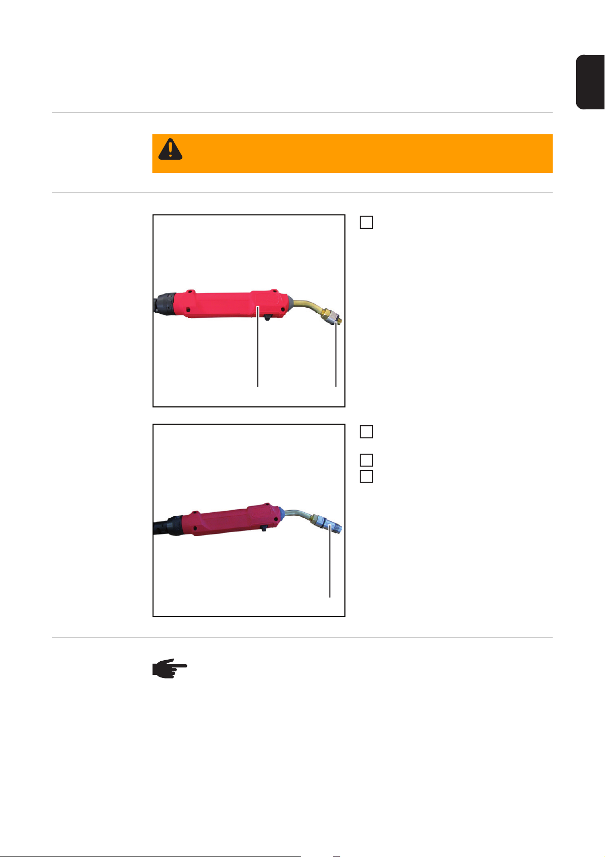
Gasdurchfluss bei MIG/MAG-Schweißbrennern der
3
TSt-Geräteserie mit Schweißbrenner-Anschluss
FSC testen
Sicherheit
Vorbereitung
WARNUNG! Fehlerhaft durchgeführte Arbeiten können schwerwiegende Per-
sonen- und Sachschäden verursachen. Nachfolgend beschriebene Arbeiten dürfen nur von Fronius-geschultem Fachpersonal durchgeführt werden!
O-Ring (2) wie abgebildet auf Adapter
1
(1) aufsetzen
DE
(3)
(2)(1)
Aufsatz FSC (3) auf Adapter schrau-
2
ben
Testbox in Betrieb nehmen
Schalter Schweißbrenner-Kategorie in
4
Stellung - MIG/MAG - schalten
13
Page 16

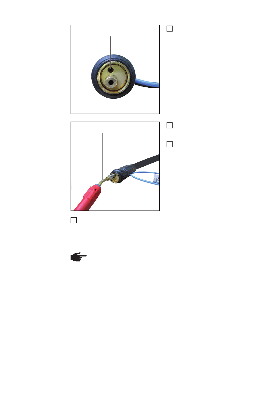
Die drei nachfolgenden Arbeitsschritte nur bei gasgekühlten Schweißbrennern durchfüh-
7
ren:
5
1
Draht-Führungsseele aus dem Schweißbrenner entfernen
6
Verschluss Stromdorn FSC (4) in den
Stromdorn (5) des zu testenden
Schweißbrenners schrauben
Gasdurchfluss
testen
(5)
(4)
HINWEIS! Während eines Testvorganges:
- das Schlauchpaket des Adapters in einer geraden Linie von der Testbox zum
Schweißbrenner auslegen
- den Schweißbrenner auf einer geeigneten Unterlage in einer geraden Linie
auflegen
14
Page 17
(1)
Adapter bis auf Anschlag auf den Gas-
1
zapfen (1) stecken
Taste Durchfluss am Adapter (2) drü-
2
cken und halten
- Gasdurchfluss wird gemessen
Angezeigten Wert am Display der
3
Testbox ablesen und mit den vorgeschriebenen Gas-Durchflussmengen
vergleichen
DE
Abschließende
Tätigkeiten
(2)
Taste Durchfluss loslassen
4
- bei Über- oder Unterschreiten der vorgeschriebenen Gas-Durchflussmengen den
Schweißbrenner auf Beschädigungen prüfen
- falls notwendig, Schweißbrenner reparieren
- nach erfolgter Reparatur Gas-Durchflusstest wiederholen
HINWEIS! Die vorgeschriebenen Gas-Durchflussmengen dem Serviceprüfplan
‘Durchflussmengen Brenner‘ (PP-SER-2001) entnehmen. Der Serviceprüfplan
‘Durchflussmengen Brenner‘ (PP-SER-2001) ist im Downloadcenter verfügbar.
Die nachfolgenden Arbeitsschritte nur bei gasgekühlten Schweißbrennern durchführen:
15
Page 18
Verschluss Stromdorn FSC (4) aus
2
3
1
dem Stromdorn (5) schrauben
(5)
(4)
Draht-Führungsseele gemäß Bedienungsanleitung des Schweißbrenners montieren
1
16
Page 19

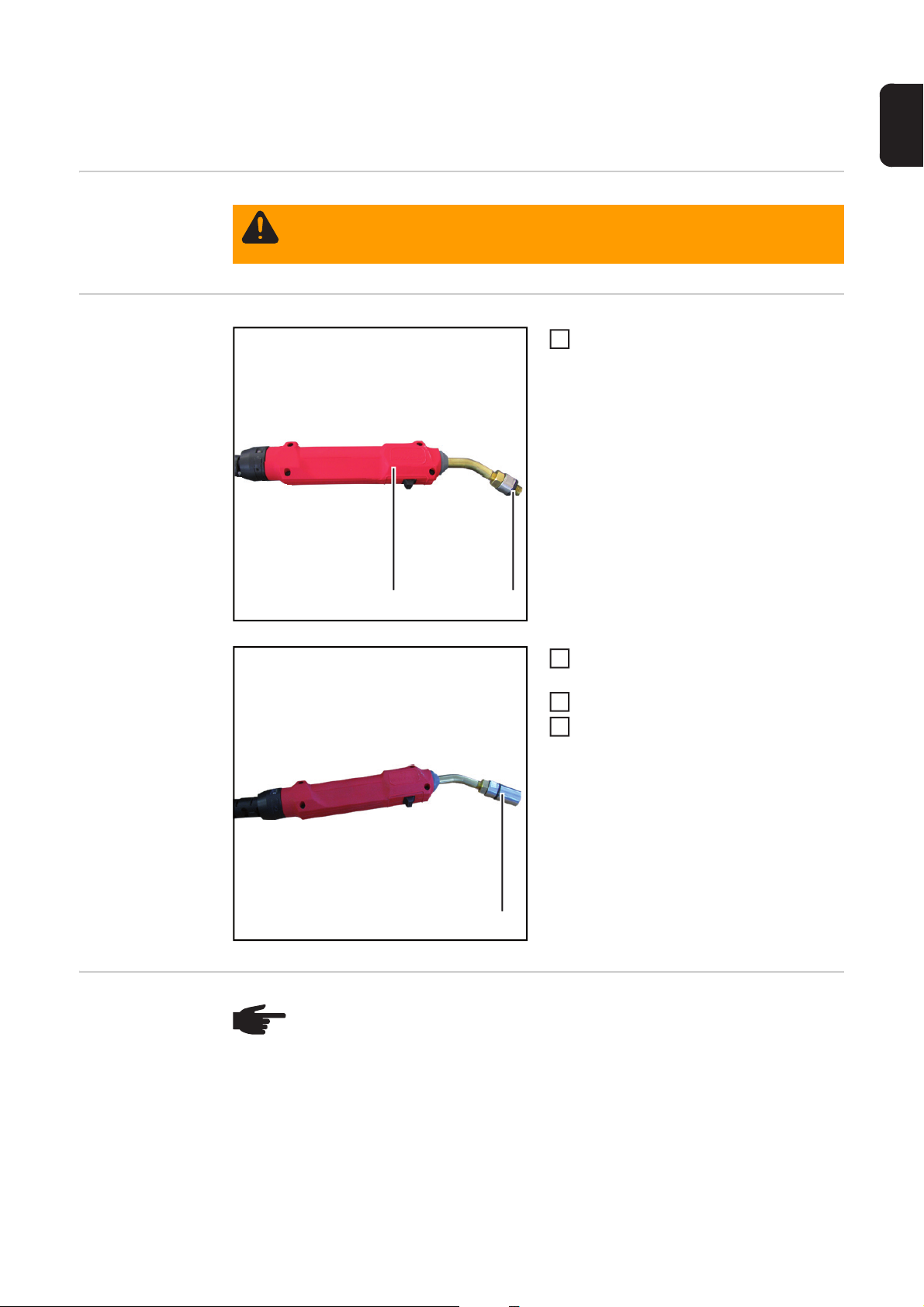
Gasdurchfluss bei MIG/MAG-Schweißbrennern der
3
TPSi-Geräteserie mit Schweißbrenner-Anschluss
FSC testen
Sicherheit
Vorbereitung
WARNUNG! Fehlerhaft durchgeführte Arbeiten können schwerwiegende Per-
sonen- und Sachschäden verursachen. Nachfolgend beschriebene Arbeiten dürfen nur von Fronius-geschultem Fachpersonal durchgeführt werden!
O-Ring (2) wie abgebildet auf Adapter
1
(1) aufsetzen
DE
(3)
(2)(1)
Aufsatz FSC (3) auf Adapter schrau-
2
ben
Testbox in Betrieb nehmen
Schalter Schweißbrenner-Kategorie in
4
Stellung - MIG/MAG - schalten
17
Page 20

Die drei nachfolgenden Arbeitsschritte nur bei gasgekühlten Schweißbrennern durchfüh-
7
ren:
5
1
Draht-Führungsseele aus dem Schweißbrenner entfernen
6
Verschluss Stromdorn FSC-G TPSi (4)
in den Stromdorn (5) des zu testenden
Schweißbrenners schrauben
Gasdurchfluss
testen
(5)
(4)
HINWEIS! Während eines Testvorganges:
- das Schlauchpaket des Adapters in einer geraden Linie von der Testbox zum
Schweißbrenner auslegen
- den Schweißbrenner auf einer geeigneten Unterlage in einer geraden Linie
auflegen
18
Page 21

(1)
Adapter bis auf Anschlag auf den Gas-
1
zapfen (1) stecken
Taste Durchfluss am Adapter (2) drü-
2
cken und halten
- Gasdurchfluss wird gemessen
Angezeigten Wert am Display der
3
Testbox ablesen und mit den vorgeschriebenen Gas-Durchflussmengen
vergleichen
DE
Abschließende
Tätigkeiten
(2)
Taste Durchfluss loslassen
4
- bei Über- oder Unterschreiten der vorgeschriebenen Gas-Durchflussmengen den
Schweißbrenner auf Beschädigungen prüfen
- falls notwendig, Schweißbrenner reparieren
- nach erfolgter Reparatur Gas-Durchflusstest wiederholen
HINWEIS! Die vorgeschriebenen Gas-Durchflussmengen dem Serviceprüfplan
‘Durchflussmengen Brenner‘ (PP-SER-2001) entnehmen. Der Serviceprüfplan
‘Durchflussmengen Brenner‘ (PP-SER-2001) ist im Downloadcenter verfügbar.
Die nachfolgenden Arbeitsschritte nur bei gasgekühlten Schweißbrennern durchführen:
19
Page 22

Verschluss Stromdorn FSC-G TPSi (4)
2
3
1
aus dem Stromdorn (5) schrauben
(5)
(4)
Draht-Führungsseele gemäß Bedienungsanleitung des Schweißbrenners montieren
1
20
Page 23

Gasdurchfluss bei MIG/MAG-Schweißbrennern mit
3
Schweißbrenner-Anschluss F++ testen
Sicherheit
Vorbereitung
WARNUNG! Fehlerhaft durchgeführte Arbeiten können schwerwiegende Per-
sonen- und Sachschäden verursachen. Nachfolgend beschriebene Arbeiten dürfen nur von Fronius-geschultem Fachpersonal durchgeführt werden!
O-Ring (2) wie abgebildet auf Adapter
1
(1) aufsetzen
DE
Gasdurchfluss
testen
(2)(1)
Aufsatz F-ZA / WIG-EC (3) auf Adapter
2
schrauben
Testbox in Betrieb nehmen
Schalter Schweißbrenner-Kategorie in
4
Stellung - MIG/MAG - schalten
(3)
HINWEIS! Während eines Testvorganges:
- das Schlauchpaket des Adapters in einer geraden Linie von der Testbox zum
Schweißbrenner auslegen
- den Schweißbrenner auf einer geeigneten Unterlage in einer geraden Linie
auflegen
21
Page 24

(1)
(2)
Adapter bis auf Anschlag in die Gas-
1
bohrung (1) stecken
Taste Durchfluss am Adapter (2) drü-
2
cken und halten
- Gasdurchfluss wird gemessen
Angezeigten Wert am Display der
3
Testbox ablesen und mit den vorgeschriebenen Gas-Durchflussmengen
vergleichen
Taste Durchfluss loslassen
4
- bei Über- oder Unterschreiten der vorgeschriebenen Gas-Durchflussmengen den
Schweißbrenner auf Beschädigungen prüfen
- falls notwendig, Schweißbrenner reparieren
- nach erfolgter Reparatur Gas-Durchflusstest wiederholen
HINWEIS! Die vorgeschriebenen Gas-Durchflussmengen dem Serviceprüfplan
‘Durchflussmengen Brenner‘ (PP-SER-2001) entnehmen. Der Serviceprüfplan
‘Durchflussmengen Brenner‘ (PP-SER-2001) ist im Downloadcenter verfügbar.
22
Page 25

Gasdurchfluss bei MIG/MAG-Schweißbrennern mit
(3)
3
Schweißbrenner-Anschluss Euro testen
Sicherheit
Vorbereitung
WARNUNG! Fehlerhaft durchgeführte Arbeiten können schwerwiegende Per-
sonen- und Sachschäden verursachen. Nachfolgend beschriebene Arbeiten dürfen nur von Fronius-geschultem Fachpersonal durchgeführt werden!
O-Ring (2) wie abgebildet auf Adapter
1
(1) aufsetzen
DE
Gasdurchfluss
testen
(2)(1)
Aufsatz EC (3) auf Adapter schrauben
2
Testbox in Betrieb nehmen
Schalter Schweißbrenner-Kategorie in
4
Stellung - MIG/MAG - schalten
HINWEIS! Während eines Testvorganges:
- das Schlauchpaket des Adapters in einer geraden Linie von der Testbox zum
Schweißbrenner auslegen
- den Schweißbrenner auf einer geeigneten Unterlage in einer geraden Linie
auflegen
23
Page 26

(1)
(2)
Adapter bis auf Anschlag auf den Gas-
1
zapfen (1) stecken
Taste Durchfluss am Adapter (2) drü-
2
cken und halten
- Gasdurchfluss wird gemessen
Angezeigten Wert am Display der
3
Testbox ablesen und mit den vorgeschriebenen Gas-Durchflussmengen
vergleichen
Taste Durchfluss loslassen
4
- bei Über- oder Unterschreiten der vorgeschriebenen Gas-Durchflussmengen den
Schweißbrenner auf Beschädigungen prüfen
- falls notwendig, Schweißbrenner reparieren
- nach erfolgter Reparatur Gas-Durchflusstest wiederholen
HINWEIS! Die vorgeschriebenen Gas-Durchflussmengen dem Serviceprüfplan
‘Durchflussmengen Brenner‘ (PP-SER-2001) entnehmen. Der Serviceprüfplan
‘Durchflussmengen Brenner‘ (PP-SER-2001) ist im Downloadcenter verfügbar.
24
Page 27
Gasdurchfluss bei WIG-Schweißbrennern mit einem
3
1/4 Zoll Gasanschluss testen
Sicherheit
Vorbereitung
WARNUNG! Fehlerhaft durchgeführte Arbeiten können schwerwiegende Per-
sonen- und Sachschäden verursachen. Nachfolgend beschriebene Arbeiten dürfen nur von Fronius-geschultem Fachpersonal durchgeführt werden!
O-Ring (2) wie abgebildet auf Adapter
1
(1) aufsetzen
DE
Gasdurchfluss
testen
(2)(1)
Aufsatz 1/4 WIG / PLASMA (3) auf Ad-
2
apter schrauben
Testbox in Betrieb nehmen
Schalter Schweißbrenner-Kategorie in
4
Stellung - WIG - schalten
(3)
HINWEIS! Während eines Testvorganges:
- das Schlauchpaket des Adapters in einer geraden Linie von der Testbox zum
Schweißbrenner auslegen
- den Schweißbrenner auf einer geeigneten Unterlage in einer geraden Linie
auflegen
25
Page 28

(1)
Anschluss ‘GAS‘ (1) auf Aufsatz 1/4
1
WIG / PLASMA am Adapter schrauben
Taste Durchfluss am Adapter (2) drü-
2
cken und halten
- Gasdurchfluss wird gemessen
Angezeigten Wert am Display der
3
Testbox ablesen und mit den vorgeschriebenen Gas-Durchflussmengen
vergleichen
(2)
Taste Durchfluss loslassen
4
- bei Über- oder Unterschreiten der vorgeschriebenen Gas-Durchflussmengen den
Schweißbrenner auf Beschädigungen prüfen
- falls notwendig, Schweißbrenner reparieren
- nach erfolgter Reparatur Gas-Durchflusstest wiederholen
HINWEIS! Die vorgeschriebenen Gas-Durchflussmengen dem Serviceprüfplan
‘Durchflussmengen Brenner‘ (PP-SER-2001) entnehmen. Der Serviceprüfplan
‘Durchflussmengen Brenner‘ (PP-SER-2001) ist im Downloadcenter verfügbar.
26
Page 29

Gasdurchfluss bei WIG-Schweißbrennern mit
3
Schweißbrenner-Anschluss Euro testen
Sicherheit
Vorbereitung
WARNUNG! Fehlerhaft durchgeführte Arbeiten können schwerwiegende Per-
sonen- und Sachschäden verursachen. Nachfolgend beschriebene Arbeiten dürfen nur von Fronius-geschultem Fachpersonal durchgeführt werden!
O-Ring (2) wie abgebildet auf Adapter
1
(1) aufsetzen
DE
Gasdurchfluss
testen
(2)(1)
Aufsatz F-ZA / WIG-EC (3) auf Adapter
2
schrauben
Testbox in Betrieb nehmen
Schalter Schweißbrenner-Kategorie in
4
Stellung - WIG - schalten
(3)
HINWEIS! Während eines Testvorganges:
- das Schlauchpaket des Adapters in einer geraden Linie von der Testbox zum
Schweißbrenner auslegen
- den Schweißbrenner auf einer geeigneten Unterlage in einer geraden Linie
auflegen
27
Page 30
(2)
(1)
Adapter bis auf Anschlag in die Gas-
1
bohrung (1) stecken
Taste Durchfluss am Adapter (2) drü-
2
cken und halten
- Gasdurchfluss wird gemessen
Angezeigten Wert am Display der
3
Testbox ablesen und mit den vorgeschriebenen Gas-Durchflussmengen
vergleichen
Taste Durchfluss loslassen
4
- bei Über- oder Unterschreiten der vorgeschriebenen Gas-Durchflussmengen den
Schweißbrenner auf Beschädigungen prüfen
- falls notwendig, Schweißbrenner reparieren
- nach erfolgter Reparatur Gas-Durchflusstest wiederholen
HINWEIS! Die vorgeschriebenen Gas-Durchflussmengen dem Serviceprüfplan
‘Durchflussmengen Brenner‘ (PP-SER-2001) entnehmen. Der Serviceprüfplan
‘Durchflussmengen Brenner‘ (PP-SER-2001) ist im Downloadcenter verfügbar.
28
Page 31
Gasdurchfluss bei TTG/TTW-Schweißbrennern tes-
3
ten
Sicherheit
Vorbereitung
WARNUNG! Fehlerhaft durchgeführte Arbeiten können schwerwiegende Per-
sonen- und Sachschäden verursachen. Nachfolgend beschriebene Arbeiten dürfen nur von Fronius-geschultem Fachpersonal durchgeführt werden!
O-Ring (2) wie abgebildet auf Adapter
1
(1) aufsetzen
DE
Gasdurchfluss
testen
(2)(1)
Aufsatz TTG/TTW (3) auf Adapter
2
schrauben
Testbox in Betrieb nehmen
Schalter Schweißbrenner-Kategorie in
4
Stellung - WIG - schalten
(3)
HINWEIS! Während eines Testvorganges:
- das Schlauchpaket des Adapters in einer geraden Linie von der Testbox zum
Schweißbrenner auslegen
- den Schweißbrenner auf einer geeigneten Unterlage in einer geraden Linie
auflegen
29
Page 32

Adapter (1) wie abgebildet bis auf An-
3
(1)
Taste Durchfluss loslassen
4
- bei Über- oder Unterschreiten der vorgeschriebenen Gas-Durchflussmengen den
Schweißbrenner auf Beschädigungen prüfen
- falls notwendig, Schweißbrenner reparieren
- nach erfolgter Reparatur Gas-Durchflusstest wiederholen
HINWEIS! Die vorgeschriebenen Gas-Durchflussmengen dem Serviceprüfplan
‘Durchflussmengen Brenner‘ (PP-SER-2001) entnehmen. Der Serviceprüfplan
‘Durchflussmengen Brenner‘ (PP-SER-2001) ist im Downloadcenter verfügbar.
1
schlag auf das Schlauchpaket stecken
Taste Durchfluss am Adapter drücken
2
und halten
- Gasdurchfluss wird gemessen
Angezeigten Wert am Display der
Testbox ablesen und mit den vorgeschriebenen Gas-Durchflussmengen
vergleichen
30
Page 33

Gasdurchfluss bei AL/PL 10/16/22-1/27-1 Schweiß-
3
brennern testen
Sicherheit
Vorbereitung
WARNUNG! Fehlerhaft durchgeführte Arbeiten können schwerwiegende Per-
sonen- und Sachschäden verursachen. Nachfolgend beschriebene Arbeiten dürfen nur von Fronius-geschultem Fachpersonal durchgeführt werden!
O-Ring (2) wie abgebildet auf Adapter
1
(1) aufsetzen
DE
Gasdurchfluss
testen
(2)(1)
Aufsatz 3/8 WIG / PLASMA (3) auf Ad-
2
apter schrauben
Testbox in Betrieb nehmen
Schalter Schweißbrenner-Kategorie in
4
Stellung - WIG - schalten
(3)
HINWEIS! Während eines Testvorganges:
- das Schlauchpaket des Adapters in einer geraden Linie von der Testbox zum
Schweißbrenner auslegen
- den Schweißbrenner auf einer geeigneten Unterlage in einer geraden Linie
auflegen
31
Page 34

Anschluss (1) des Schweißbrenners
(2)
(1)
3
1
auf Aufsatz 3/8 WIG / PLASMA am Adapter (2) schrauben
Taste Durchfluss am Adapter (2) drü-
2
cken und halten
- Gasdurchfluss wird gemessen
Angezeigten Wert am Display der
Testbox ablesen und mit den vorgeschriebenen Gas-Durchflussmengen
vergleichen
Taste Durchfluss loslassen
4
- bei Über- oder Unterschreiten der vorgeschriebenen Gas-Durchflussmengen den
Schweißbrenner auf Beschädigungen prüfen
- falls notwendig, Schweißbrenner reparieren
- nach erfolgter Reparatur Gas-Durchflusstest wiederholen
HINWEIS! Die vorgeschriebenen Gas-Durchflussmengen dem Serviceprüfplan
‘Durchflussmengen Brenner‘ (PP-SER-2001) entnehmen. Der Serviceprüfplan
‘Durchflussmengen Brenner‘ (PP-SER-2001) ist im Downloadcenter verfügbar.
32
Page 35

Plasmagas-Durchfluss bei PTW-Schweißbrennern
3
mit Schweißbrenner-Anschluss F++ testen
Sicherheit
Vorbereitung
WARNUNG! Fehlerhaft durchgeführte Arbeiten können schwerwiegende Per-
sonen- und Sachschäden verursachen. Nachfolgend beschriebene Arbeiten dürfen nur von Fronius-geschultem Fachpersonal durchgeführt werden!
O-Ring (2) wie abgebildet auf Adapter
1
(1) aufsetzen
DE
PlasmagasDurchfluss testen
(2)(1)
Aufsatz 1/4 WIG / PLASMA (3) auf Ad-
2
apter schrauben
Testbox in Betrieb nehmen
Schalter Schweißbrenner-Kategorie in
4
Stellung - WIG - schalten
(3)
HINWEIS! Während eines Testvorganges:
- das Schlauchpaket des Adapters in einer geraden Linie von der Testbox zum
Schweißbrenner auslegen
- den Schweißbrenner auf einer geeigneten Unterlage in einer geraden Linie
auflegen
33
Page 36

Adapter (1) wie abgebildet bis auf An-
3
1
schlag auf den Bajonettverschluss (2)
stecken
Taste Durchfluss am Adapter drücken
2
und halten
- Durchfluss wird gemessen
Angezeigten Wert am Display der
(2)
Testbox ablesen und mit den vorgeschriebenen Durchflussmengen vergleichen
(1)
Taste Durchfluss loslassen
4
- bei Über- oder Unterschreiten der vorgeschriebenen Durchflussmengen den
Schweißbrenner auf Beschädigungen prüfen
- falls notwendig, Schweißbrenner reparieren
- nach erfolgter Reparatur Durchflusstest wiederholen
HINWEIS! Die vorgeschriebenen Gas-Durchflussmengen dem Serviceprüfplan
‘Durchflussmengen Brenner‘ (PP-SER-2001) entnehmen. Der Serviceprüfplan
‘Durchflussmengen Brenner‘ (PP-SER-2001) ist im Downloadcenter verfügbar.
34
Page 37

Gasdurchfluss bei PTW-Z-Schweißbrennern testen
3
DE
Sicherheit
Vorbereitung
WARNUNG! Fehlerhaft durchgeführte Arbeiten können schwerwiegende Per-
sonen- und Sachschäden verursachen. Nachfolgend beschriebene Arbeiten dürfen nur von Fronius-geschultem Fachpersonal durchgeführt werden!
O-Ring (2) wie abgebildet auf Adapter
1
(1) aufsetzen
(2)(1)
Aufsatz PTW-Z (3) auf Adapter schrau-
2
ben
Testbox in Betrieb nehmen
Schalter Schweißbrenner-Kategorie in
4
Stellung - WIG - schalten
(3)
Gasdurchfluss
testen
HINWEIS! Während eines Testvorganges:
- das Schlauchpaket des Adapters in einer geraden Linie von der Testbox zum
Schweißbrenner auslegen
- den Schweißbrenner auf einer geeigneten Unterlage in einer geraden Linie
auflegen
35
Page 38

Gasschlauch (1) des Schlauchpaketes
3
(2) (1)
Taste Durchfluss loslassen
4
- bei Über- oder Unterschreiten der vorgeschriebenen Durchflussmengen den
Schweißbrenner auf Beschädigungen prüfen
- falls notwendig, Schweißbrenner reparieren
- nach erfolgter Reparatur Durchflusstest wiederholen
HINWEIS! Die vorgeschriebenen Gas-Durchflussmengen dem Serviceprüfplan
‘Durchflussmengen Brenner‘ (PP-SER-2001) entnehmen. Der Serviceprüfplan
‘Durchflussmengen Brenner‘ (PP-SER-2001) ist im Downloadcenter verfügbar.
1
wie abgebildet in den Aufsatz des Adapters (2) stecken
Taste Durchfluss am Adapter drücken
2
und halten
- Durchfluss wird gemessen
Angezeigten Wert am Display der
Testbox ablesen und mit den vorgeschriebenen Durchflussmengen vergleichen
36
Page 39

Plasmagas-Durchfluss bei PTW-Z-Schweißbrennern
3
testen
Sicherheit
Vorbereitung
WARNUNG! Fehlerhaft durchgeführte Arbeiten können schwerwiegende Per-
sonen- und Sachschäden verursachen. Nachfolgend beschriebene Arbeiten dürfen nur von Fronius-geschultem Fachpersonal durchgeführt werden!
O-Ring (2) wie abgebildet auf Adapter
1
(1) aufsetzen
DE
PlasmagasDurchfluss testen
(2)(1)
Aufsatz 1/4 WIG / PLASMA (3) auf Ad-
2
apter schrauben
Testbox in Betrieb nehmen
Schalter Schweißbrenner-Kategorie in
4
Stellung - WIG - schalten
(3)
HINWEIS! Während eines Testvorganges:
- das Schlauchpaket des Adapters in einer geraden Linie von der Testbox zum
Schweißbrenner auslegen
- den Schweißbrenner auf einer geeigneten Unterlage in einer geraden Linie
auflegen
37
Page 40

Plasmagas-Schlauch (1) des
3
1
Schlauchpaketes auf den Aufsatz des
Adapters (2) schrauben
Taste Durchfluss am Adapter drücken
2
und halten
- Durchfluss wird gemessen
Angezeigten Wert am Display der
(1)
(2)
Taste Durchfluss loslassen
4
- bei Über- oder Unterschreiten der vorgeschriebenen Durchflussmengen den
Schweißbrenner auf Beschädigungen prüfen
- falls notwendig, Schweißbrenner reparieren
- nach erfolgter Reparatur Durchflusstest wiederholen
HINWEIS! Die vorgeschriebenen Gas-Durchflussmengen dem Serviceprüfplan
‘Durchflussmengen Brenner‘ (PP-SER-2001) entnehmen. Der Serviceprüfplan
‘Durchflussmengen Brenner‘ (PP-SER-2001) ist im Downloadcenter verfügbar.
Testbox ablesen und mit den vorgeschriebenen Durchflussmengen vergleichen
38
Page 41
Pflege, Wartung und Entsorgung
DE
Sicherheit
WARNUNG! Fehlerhaft durchgeführte Arbeiten können schwerwiegende Per-
sonen- und Sachschäden verursachen. Alle in der Bedienungsanleitung beschriebenen Arbeiten dürfen nur von geschultem Fachpersonal durchgeführt
werden. Das Fachpersonal muss von der Fa. Fronius eine Schulung zur ordnungsgemäßen Bedienung des Gerätes erhalten haben. Die beschriebenen Arbeiten erst durchführen, wenn folgende Dokumente vollständig gelesen und
verstanden wurden:
- diese Bedienungsanleitung
- sämtliche Bedienungsanleitungen der Systemkomponenten, insbesondere
Sicherheitsvorschriften
WARNUNG! Ein elektrischer Schlag kann tödlich sein. Vor Beginn der Arbeiten:
- Netzschalter des Gerätes in Stellung - O - schalten
- Gerät vom Netz trennen
- sicherstellen, dass das Gerät bis zum Abschluss aller Arbeiten vom Netz ge-
trennt bleibt
- das Gerät von der Druckluft-Versorgung trennen
- sicherstellen, dass das Gerät bis zum Abschluss aller Arbeiten von der
Druckluft-Versorgung getrennt bleibt
Nach dem Öffnen des Gerätes mit Hilfe eines geeigneten Messgerätes sicherstellen, dass elektrisch geladene Bauteile (z.B. Kondensatoren) entladen sind.
WARNUNG! Unzureichende Schutzleiter-Verbindung kann schwerwiegende
Personen- und Sachschäden verursachen. Die Gehäuse-Schrauben stellen eine
geeignete Schutzleiter-Verbindung für die Erdung des Gehäuses dar und dürfen
keinesfalls durch andere Schrauben ohne zuverlässige Schutzleiter-Verbindung
ersetzt werden.
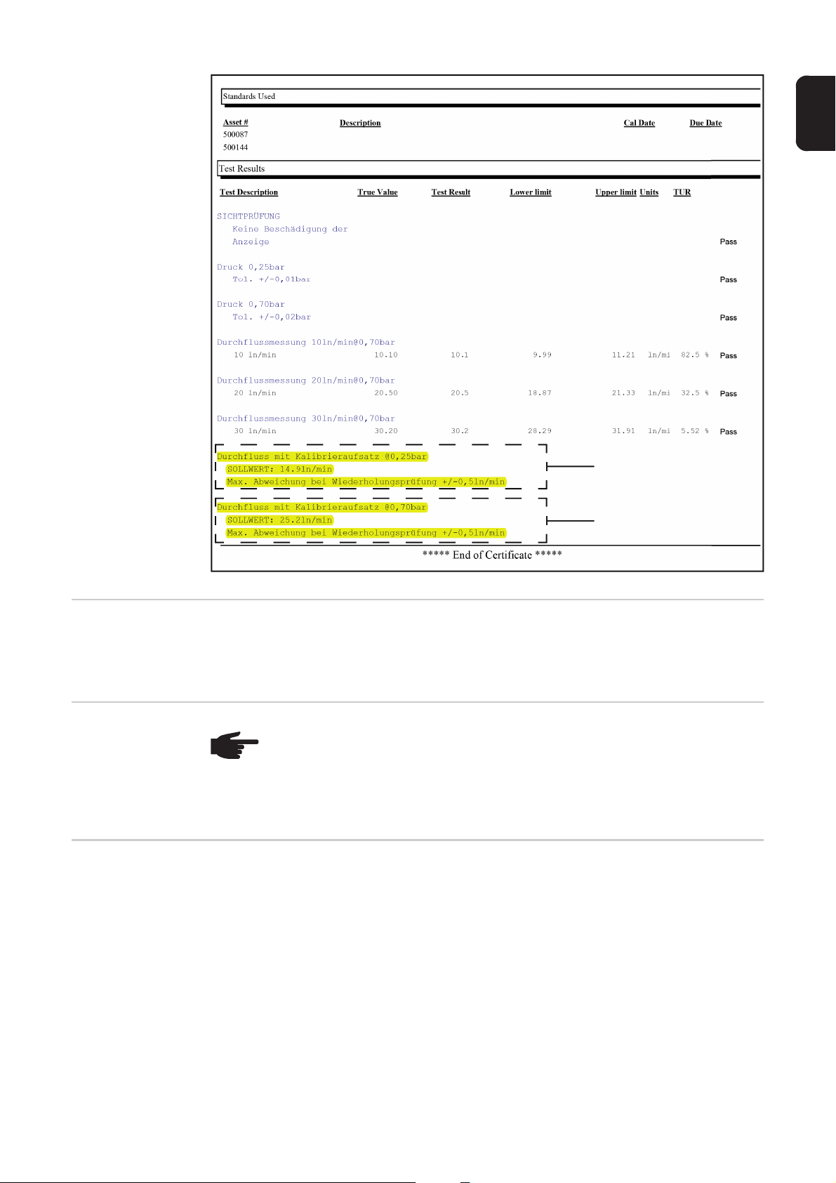
Bei jeder Inbetriebnahme
Alle 6 Monate:
Testbox kalibrieren
- Sicherstellen, dass der Netzstecker und das Netzkabel unbeschädigt sind
- Sicherstellen, dass das Schlauchpaket des Adapters unbeschädigt ist
- Sicherstellen, dass der Druckluft-Schlauch der Testbox unbeschädigt ist
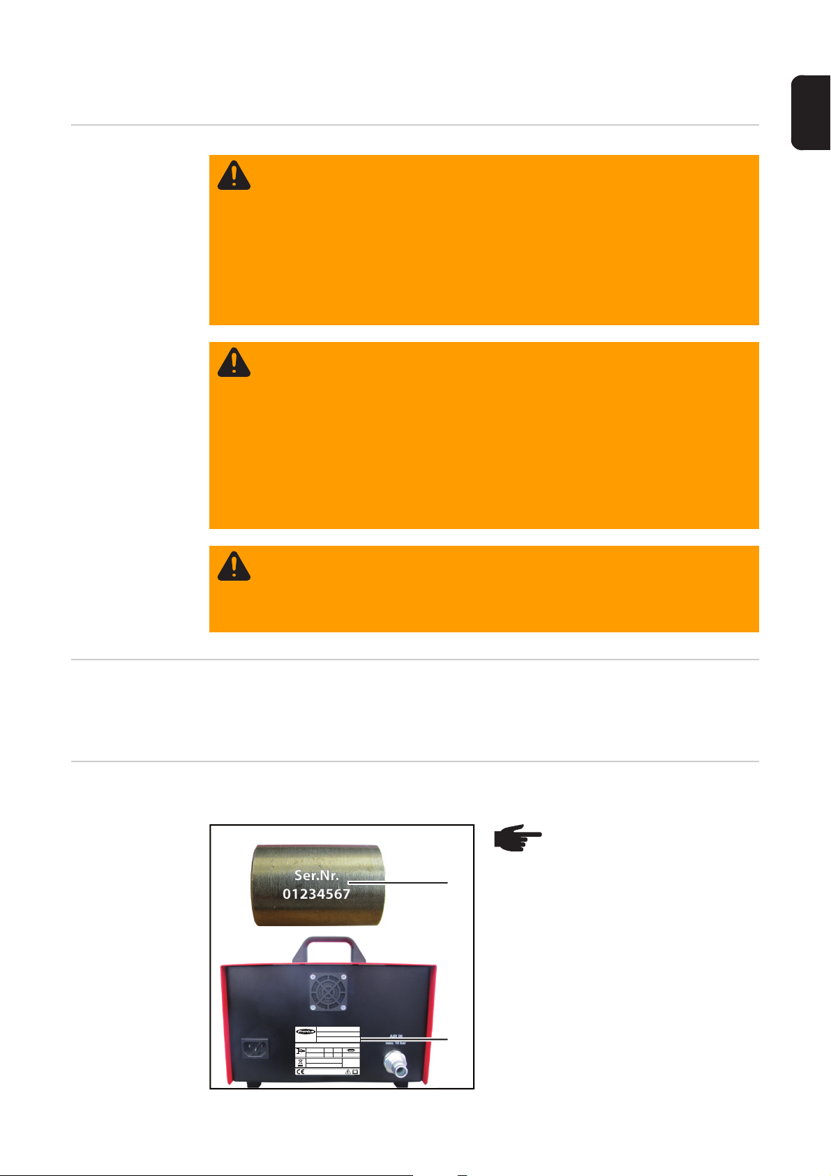
Alle 6 Monate wie folgt die Testbox kalibrieren:
HINWEIS! Die Seriennummer (1)
am Aufsatz Serinenummer muss
mit der Seriennummer (2) der
Testbox übereinstimmen.
A-4600Wels
www.fronius.com
1~
50/60 Hz
Mod.:
Part No. : 4,078,016
Ser. No.:
EN 61010-1
U
1
115/230 VAC
L x W x H
330mmx235mmx220mm
2011
Testbox - Torch Flow Rate
01234567
P
max in
I
1
0,3A
bar
10
(1)
(2)
0,8 A
IP 20
39
Page 42

Das Schlauchpaket des Adapters in ei-
4
1
ner geraden Linie auslegen
O-Ring (3) wie abgebildet auf Adapter
2
(4) aufsetzen
(3)(4)
Aufsatz Seriennummer (1) auf Adapter
3
schrauben
Testbox in Betrieb nehmen
Schalter Schweißbrenner-Kategorie in
5
Stellung - MIG/MAG - schalten
Taste Durchfluss am Adapter (4) drü-
6
cken und halten
- Durchfluss wird gemessen
- der aktuelle Wert wird am Display
der Testbox angezeigt
(1)(4)
Den angezeigten Wert mit den Angaben für die Schweißbrenner-Kategorie MIG/MAG
7
im Kalibrierschein vergleichen - siehe (5) in der nachfolgenden Grafik
- stimmt der Wert mit den Angaben im Kalibrierschein überein, ist die Testbox in
Ordnung
- stimmt der Wert mit den Angaben im Kalibrierschein nicht überein, die Testbox
zur Reparatur an den Hersteller senden
Taste Durchfluss am Adapter loslassen
8
Schalter Schweißbrenner-Kategorie in Stellung - WIG - schalten
9
Taste Durchfluss am Adapter (2) drücken und halten
10
- Durchfluss wird gemessen
- der aktuelle Wert wird am Display der Testbox angezeigt
Den angezeigten Wert mit den Angaben für die Schweißbrenner-Kategorie WIG im
11
11
Kalibrierschein vergleichen - siehe (6) in der nachfolgenden Grafik
- stimmt der Wert mit den Angaben im Kalibrierschein überein, ist die Testbox in
Ordnung
- stimmt der Wert mit den Angaben im Kalibrierschein nicht überein, die Testbox
zur Reparatur an den Hersteller senden
Taste Durchfluss loslassen
12
40
Page 43
DE
(5)
(6)
Alle 6 Monate:
Lüfter auf Funktion überprüfen
Alle 24 Monate
Entsorgung Die Entsorgung nur gemäß den geltenden nationalen und regionalen Bestimmungen
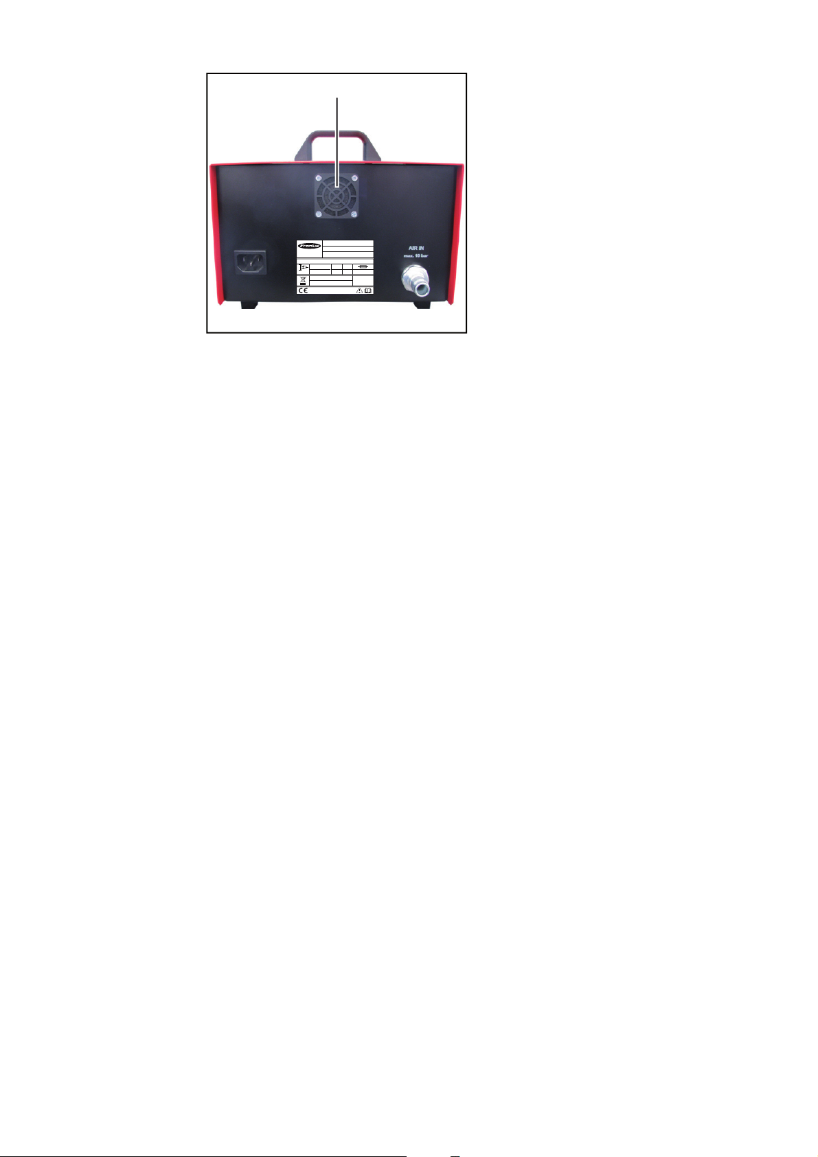
Lüfter auf Funktion überprüfen - da der Lüfter die warme Luft vom Geräteinnenraum nach
außen transportiert, muss der Luftstrom des Lüfters an der Geräteaußenseite mit der Hand
spürbar sein.
HINWEIS! Gefahr der Beschädigung elektronischer Bauteile. Elektronische Bauteile nicht aus kurzer Entfernung anblasen.
Geräte-Deckel demontieren und das Geräteinnere mit trockener, reduzierter Druckluft
sauber blasen.
durchführen.
41
Page 44

Lüfter wechseln
Sicherheit
WARNUNG! Fehlerhaft durchgeführte Arbeiten können schwerwiegende Per-
sonen- und Sachschäden verursachen. Alle in der Bedienungsanleitung beschriebenen Arbeiten dürfen nur von geschultem Fachpersonal durchgeführt
werden. Das Fachpersonal muss von der Fa. Fronius eine Schulung zur ordnungsgemäßen Bedienung des Gerätes erhalten haben. Die beschriebenen Arbeiten erst durchführen, wenn folgende Dokumente vollständig gelesen und
verstanden wurden:
- diese Bedienungsanleitung
- sämtliche Bedienungsanleitungen der Systemkomponenten, insbesondere
Sicherheitsvorschriften
WARNUNG! Ein elektrischer Schlag kann tödlich sein. Vor Beginn der Arbeiten:
- Netzschalter des Gerätes in Stellung - O - schalten
- Gerät vom Netz trennen
- sicherstellen, dass das Gerät bis zum Abschluss aller Arbeiten vom Netz ge-
trennt bleibt
- das Gerät von der Druckluft-Versorgung trennen
- sicherstellen, dass das Gerät bis zum Abschluss aller Arbeiten von der
Druckluft-Versorgung getrennt bleibt
Nach dem Öffnen des Gerätes mit Hilfe eines geeigneten Messgerätes sicherstellen, dass elektrisch geladene Bauteile (z.B. Kondensatoren) entladen sind.
WARNUNG! Unzureichende Schutzleiter-Verbindung kann schwerwiegende
Personen- und Sachschäden verursachen. Die Gehäuse-Schrauben stellen eine
geeignete Schutzleiter-Verbindung für die Erdung des Gehäuses dar und dürfen
keinesfalls durch andere Schrauben ohne zuverlässige Schutzleiter-Verbindung
ersetzt werden.
Lüfter wechseln
(1)
Schrauben (1) lösen
(1)
(1)(1)
(1)
1
42
Page 45

(2)
5
(2)
Schrauben (2) lösen
2
Gehäuseabdeckung entfernen
3
DE
(4)
(2)(2)
(3)
A-4600Wels
www.fronius.com
1~
50/60 Hz
Mod.:
Part No. : 4,078,016
Ser. No.:
EN 61010-1
U
1
115/230 VAC
L x W x H
330mmx235mmx220mm
Testbox - Torch Flow Rate
P
max in
I
1
0,3A
10
2011
(2)
Schrauben (3) lösen
4
bar
0,8 A
IP 20
(3)(3)(3)
Stecker (4) abstecken
Lüfter entnehmen
6
Neuen Lüfter in das Gehäuse einset-
7
zen, mittels Schrauben (3) festschrauben und in der Testbox anstecken
Gehäuseabdeckung auf die Testbox
8
aufsetzen und mittels Schrauben (1)
und (2) festschrauben
43
Page 46

Technische Daten
Testbox - Torch
Flow Rate
Netzspannung 1 (U
Netzfrequenz 50 / 60 Hz
Nenndruck 10 bar
Netzabsicherung 0,8 A
Nennstrom 0,3 A
Maße l x b x h 330 x 235 x 220
Schutzart IP 20
Prüfzeichen CE
) 115 V - 230 V
1
145.04 psi
12.99 x 9.52 x 8.66 in.
44
Page 47

Ersatzteile
(2)
(3)
(4)
(5)
(6)
(7)
(8)
(9)
(10)
(12)
(13)
(14)
(11)
DE
Ersatzteile
(1) Adapter (43,0001,3357)
(1)
(2) O-Ring (42,0402,0009)
(3) Verschluss Stromdorn FSC
(42,0001,6438)
passender O-Ring (42,0402,0083)
(4) Aufsatz TTG/TTW (42,0001,0026)
(5) Aufsatz F-ZA / WIG-EC
(42,0001,0029)
passender O-Ring (42,0402,0153)
(6) Aufsatz Push-In (42,0001,0024)
passender O-Ring (42,0402,0153)
(7) Aufsatz 1/4 WIG / PLASMA
(42,0001,0027)
(8) Aufsatz EC (42,0001,0028)
(9) Aufsatz FSC (42,0001,0025)
(10) Aufsatz 3/8 WIG / PLASMA
(42,0001,4471)
(11) Kupplung (44,0001,1145)
(12) O-Ring (42,0001,0236)
(13) Aufsatz PTW-Z (42,0001,4470)
(14) Verschluss Stromdorn FSC-G TPSi
(42,0001,4521)
passender O-Ring (42,0300,2719)
45
Page 48
A-4600Wels
www.fronius.com
1~
50/60 Hz
(15)
Testbox - Torch Flow Rate
Mod.:
Part No. : 4,078,016
Ser. No.:
EN 61010-1
U
1
0,3A
115/230 VAC
L x W x H
330mmx235mmx220mm
2011
(15) Lüfter für Testbox (43,0001,3356)
P
max in
I
1
bar
0,8 A
10
IP 20
46
Page 49

Dear reader,
Introduction Thank you for the trust you have placed in our company and congratulations on buying this
high-quality Fronius product. These instructions will help you familiarise yourself with the
product. Reading the instructions carefully will enable you to learn about the many different
features it has to offer. This will allow you to make full use of its advantages.
Please also note the safety rules to ensure greater safety when using the product. Careful
handling of the product will repay you with years of safe and reliable operation. These are
essential prerequisites for excellent results.
EN
47
Page 50

48
Page 51

Contents
General ...................................................................................................................................................... 51
Device concept ..................................................................................................................................... 51
Proper use ............................................................................................................................................ 51
Warning notices on the device.............................................................................................................. 51
Mains connection .................................................................................................................................. 52
Compressed air supply specifications................................................................................................... 52
Specified gas flow rates ........................................................................................................................ 52
Safety.................................................................................................................................................... 52
Scope of supply ......................................................................................................................................... 54
Scope of supply .................................................................................................................................... 54
Control elements and connections............................................................................................................. 56
Controls and connections on the testbox.............................................................................................. 56
Control elements on the adapter........................................................................................................... 57
Starting the testbox .................................................................................................................................... 58
Starting the testbox............................................................................................................................... 58
Checking gas flow rate on TSt series MIG/MAG welding torches with FSC torch connector .................... 59
Safety.................................................................................................................................................... 59
Preparations.......................................................................................................................................... 59
Checking the gas flow rate.................................................................................................................... 60
And finally... .......................................................................................................................................... 61
Checking gas flow rate on TPSi series MIG/MAG welding torches with FSC torch connector .................. 63
Safety.................................................................................................................................................... 63
Preparations.......................................................................................................................................... 63
Checking the gas flow rate.................................................................................................................... 64
And finally... .......................................................................................................................................... 65
Checking gas flow rate on MIG/MAG welding torches with F++ torch connector ...................................... 67
Safety.................................................................................................................................................... 67
Preparations.......................................................................................................................................... 67
Checking the gas flow rate.................................................................................................................... 67
Checking gas flow rate on MIG/MAG welding torches with Euro torch connector ..................................... 69
Safety.................................................................................................................................................... 69
Preparations.......................................................................................................................................... 69
Checking the gas flow rate.................................................................................................................... 69
Checking gas flow rate on TIG welding torches with a 1/4 inch gas connection ....................................... 71
Safety.................................................................................................................................................... 71
Preparations.......................................................................................................................................... 71
Checking the gas flow rate.................................................................................................................... 71
Checking gas flow rate on TIG welding torches with Euro torch connector ............................................... 73
Safety.................................................................................................................................................... 73
Preparations.......................................................................................................................................... 73
Checking the gas flow rate.................................................................................................................... 73
Checking gas flow rate on TTG/TTW welding torches...............................................................................75
Safety.................................................................................................................................................... 75
Preparations.......................................................................................................................................... 75
Checking the gas flow rate.................................................................................................................... 75
Checking gas flow rate on AL/PL 10/16/22-1/27-1 welding torches .......................................................... 77
Safety.................................................................................................................................................... 77
Preparations.......................................................................................................................................... 77
Checking the gas flow rate.................................................................................................................... 77
Checking plasma gas flow rate on PTW welding torches with F++ torch connector ................................. 79
Safety.........................................................................................................................
Preparations.......................................................................................................................................... 79
Checking the plasma gas flow rate ....................................................................................................... 79
Checking gas flow rate on PTW-Z welding torches ................................................................................... 81
Safety.................................................................................................................................................... 81
Preparations.......................................................................................................................................... 81
Checking the gas flow rate.................................................................................................................... 81
Checking plasma gas flow rate on PTW-Z welding torches....................................................................... 83
Safety.................................................................................................................................................... 83
Preparations.......................................................................................................................................... 83
........................... 79
EN
49
Page 52

Checking the plasma gas flow rate ....................................................................................................... 83
Care, maintenance and disposal ............................................................................................................... 85
Safety.................................................................................................................................................... 85
On every start-up .................................................................................................................................. 85
Every 6 months: Calibrating the testbox ............................................................................................... 85
Every 6 months: Checking that the fan is working correctly ................................................................. 87
Every 24 months................................................................................................................................... 87
Disposal ................................................................................................................................................ 87
Changing the fan........................................................................................................................................ 88
Safety.................................................................................................................................................... 88
Changing the fan................................................................................................................................... 88
Technical data............................................................................................................................................ 90
Torch Flow Rate testbox....................................................................................................................... 90
Spare parts ................................................................................................................................................ 91
Replacement parts................................................................................................................................ 91
50
Page 53
General
330mmx235mmx220mm
2011
1~
50/60 Hz
0,8 A
0,3A
U
1
115/230 VAC
EN 61010-1
Mod.:
Ser. No.:
Part No. : 4,078,016
A-4600Wels
www.fronius.com
Testbox - Torch Flow Rate
IP 20
I
1
L x W x H
P
max in
10
bar
330mmx235mmx220mm
2011
1~
50/60 Hz
0,8 A
0,3A
U
1
115/230 VAC
EN 61010-1
Mod.:
Ser. No.:
Part No. : 4,078,016
A-4600 Wels
www.fronius.com
Testbox - Torch Flow Rate
IP 20
I
1
L x W x H
P
max in
10
bar
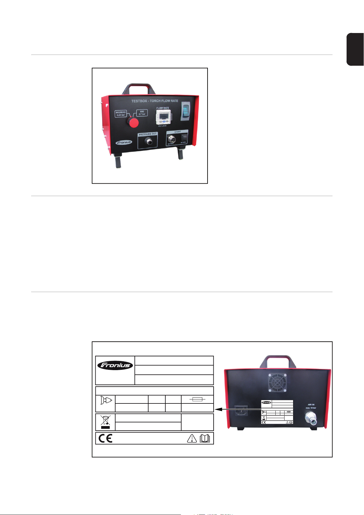
Device concept The Torch Flow Rate testbox is used to car-
ry out a gas flow test on the following Fronius welding torches
- MIG/MAG welding torches
- TIG welding torches
- Plasma torches
Proper use The Torch Flow Rate testbox is intended exclusively for testing the gas flow rate of Fronius
welding torches.
Utilisation for any other purpose, or in any other manner, shall be deemed to be not in accordance with the intended purpose.
The manufacturer shall not be held liable for any damages arising from such usage.
EN
Warning notices
on the device
Proper use also includes
- carefully reading these operating instructions
- following all the instructions and safety rules in these operating instructions
- carrying out all the specified inspection and servicing work
The device is fitted with safety symbols and a rating plate. The safety symbols and rating
plate must not be removed or painted over. The symbols warn against operating the equipment incorrectly, as this may result in serious injury and damage.
51
Page 54

Do not dispose of used devices with domestic waste. Dispose of them according to national guidelines.
Do not use the functions described here until you have thoroughly read and
understood the following documents:
- these operating instructions
- all the operating instructions for the system components, especially the
safety rules
Mains connection The device is designed to run at the mains voltage indicated on the rating plate. The fuse
protection required for the mains cable can be found in the "Technical data" section. If there
is no mains cable or mains plug on your device, fit one that conforms to national standards.
NOTE! An inadequately dimensioned electrical installation can cause serious
damage. The mains cable and its fuse must be dimensioned to suit the local power supply. The technical data shown on the rating plate applies.
Compressed air
supply specifications
Specified gas
flow rates
Safety
To ensure that the testbox functions correctly, the following compressed air supply specifications must be met:
- Compressed air is free of oil
- Compressed air is free of dust - no dirt particles larger than 5 µm
- Compressed air is free of water
- Compressed air supply at 2.5 - 10 bar (36.26 - 145.04 psi)
NOTE! For the specified gas flow rates, refer to the "Welding torch flow rates"
service test schedule (PP-SER-2001). The "Welding torch flow rates" service test
schedule (PP-SER-2001) is available from the DownloadCenter.
WARNING! Incorrect operation or shoddy workmanship can cause serious injury
or damage. All functions described in the operating instructions may only be used
by trained and qualified personnel. All activities described in the operating instructions may only be carried out by trained and qualified personnel. Personnel carrying out these activities must have received training from Fronius in the correct
operation of the device. Do not use any of the functions described or carry out the
work described until you have fully read and understood the following documents:
- these operating instructions
- all the operating instructions for the system components, especially the safety rules
52
WARNING! Work that is carried out incorrectly can cause serious injury or damage. Before starting work and carrying out tests:
- turn the power source mains switch to the "O" position
- disconnect the power source from the mains
- ensure that the power source remains disconnected from the mains until all
work has been completed
- remove the wire electrode from the welding torch
- disconnect the welding torch from all system components
Page 55

CAUTION! Risk of burns from hot welding torch components and hot coolant. Before commencing any of the work described in these operating instructions, allow
all welding torch components and the coolant to cool to room temperature (+25
°C, +77 °F).
CAUTION! On water-cooled welding torches: Risk of damage due to escaping
coolant. Drain coolant from the welding torch before starting any of the work described in these operating instructions.
EN
53
Page 56

Scope of supply
Scope of supply
(1) Torch Flow Rate testbox
(1)
(2) Adapter
(2)
(3)
(4)
(3) Compressed air hose
(4) Compressed air connection with
hose clamps
54
Page 57
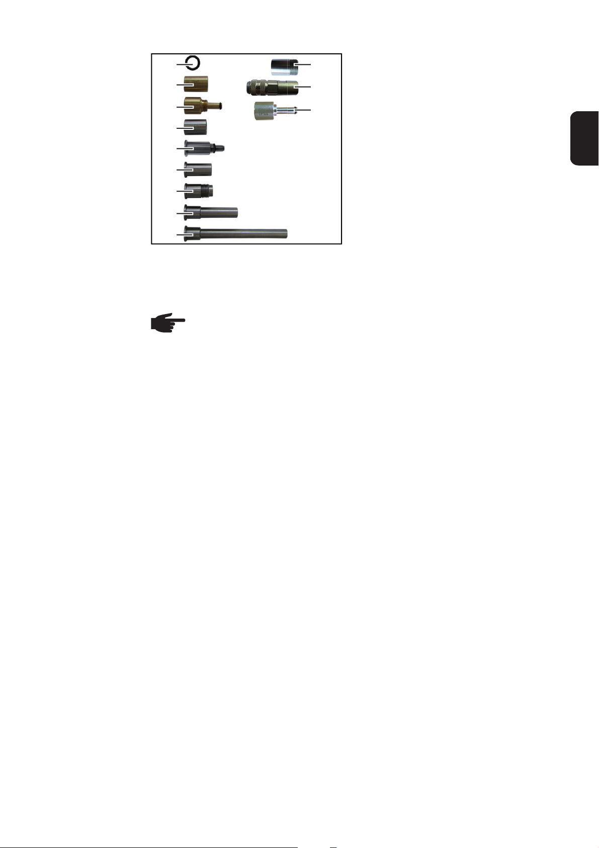
(5)
(6)
(7)
(8)
(9)
(10)
(11)
(12)
(13)
Not shown:
- Mains cable
- Operating instructions
NOTE! The attachment designations are engraved on the attachments.
(14)
(15)
(16)
(5) O-ring
(6) Serial number attachment
(7) FSC power pin cover
(8) TTG/TTW attachment
(9) F-ZA / TIG EC attachment
(10) Push In attachment
(11) 1/4 TIG / PLASMA attachment
(12) EC attachment
(13) FSC attachment
(14) 3/8 TIG / PLASMA attachment
(15) PTW-Z attachment
(16) FSC-G TPSi power pin cover
EN
55
Page 58

Control elements and connections
(8)(7)
330mmx235mmx220mm
2011
1~
50/60 Hz
0,8 A
0,3A
U
1
115/230 VAC
EN 61010-1
Mod.:
Ser. No.:
Part No. : 4,078,016
A-4600Wels
www.fronius.com
Testbox - Torch Flow Rate
IP 20
I
1
L x W x H
P
max in
10
bar
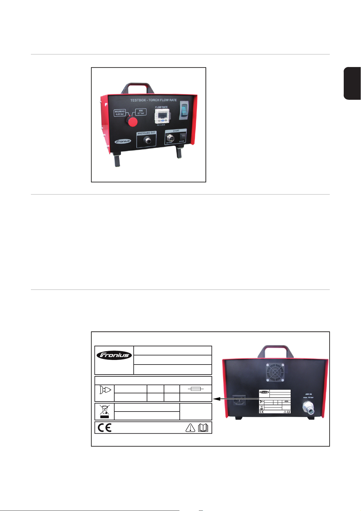
Controls and connections on the
testbox
(1) (2) (3)
(6) (5) (4)
Front of the testbox Rear of the testbox
No. Function
(1) Welding torch category switch
for selecting the welding torch category
(2) Display
shows the current flow rate
(3) Mains switch
switches the testbox on and off
(4) 'INTERN' button
starts the test (alternatively the test can be started by pressing the flow button on
the adapter)
(5) 'EXTERN' connection
for connecting the adapter control plug
(6) 'PRESSURE OUT' connection
for connecting the compressed air line from the adapter
(7) Mains cable connection
(8) Compressed air connection
for supplying the testbox with compressed air
56
Page 59
Control elements
(1)
on the adapter
No. Function
(1) Flow button
starts the test
EN
57
Page 60

Starting the testbox
6
9
11
11
Starting the testbox
(2) (3)(1)
(5) (4)
Push the hose clamp (1) onto the com-
1
pressed air hose (2)
Insert the compressed air connection
2
(3) into the compressed air hose as far
as it will go
Tighten the hose clamp in the position
3
shown
Connect the control plug (4) of the ad-
4
apter to the 'EXTERN' connection
Connect the compressed air line (5) of
5
the adapter to the 'PRESSURE OUT'
connection
58
Testbox - Torch Flow Rate
Mod.:
Part No. : 4,078,016
A-4600Wels
www.fronius.com
Ser. No.:
EN 61010-1
P
max in
U
1
I
1
1~
0,3A
115/230 VAC
bar
0,8 A
L x W x H
330mmx235mmx220mm
2011
10
IP 20
50/60 Hz
(7)
Establish the compressed air supply
12
- The testbox is now ready for use
(6)
Depressurise the compressed air supply to the testbox until all work has
been completed
Connect the loose end of the com-
7
pressed air hose (6) to the compressed
air supply
Connect the compressed air hose (6)
8
to the compressed air connection on
the testbox
Connect the mains cable (7) to the
mains cable connection on the testbox
Plug the mains cable into the mains so-
10
cket
Switch on the testbox at the mains
switch
Page 61

Checking gas flow rate on TSt series MIG/MAG weld-
3
ing torches with FSC torch connector
Safety
Preparations
WARNING! Work that is carried out incorrectly can cause serious injury and dam-
age. The work described below must only be carried out by Fronius-trained qualified personnel!
Place the O-ring (2) on the adapter (1)
1
as shown
(2)(1)
Screw the FSC attachment (3) onto the
2
adapter
Start the testbox
Turn the welding torch category switch
4
to the - MIG/MAG - position
EN
(3)
59
Page 62
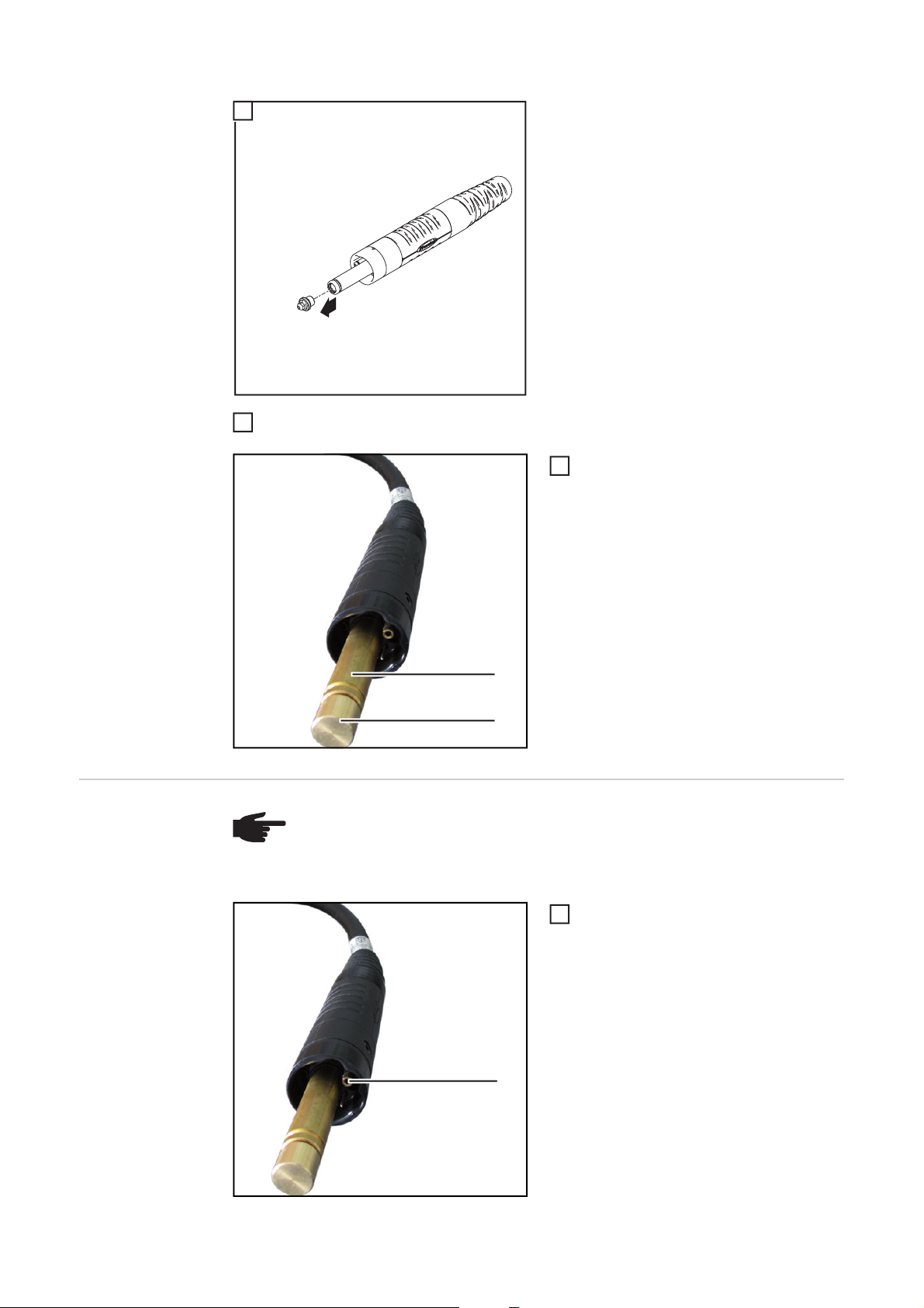
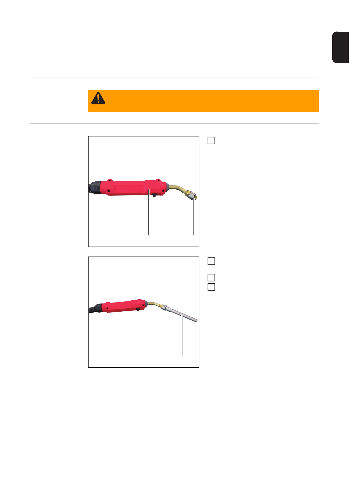
Only carry out the three steps described below on gas-cooled welding torches:
7
5
1
Remove the inner liner from the welding torch
6
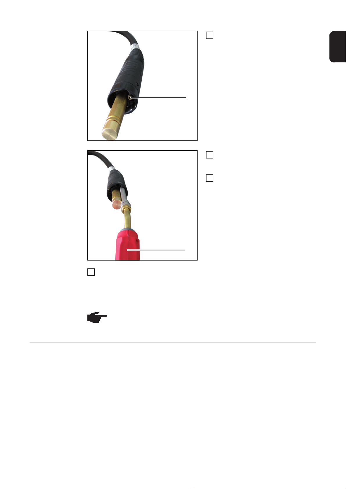
Screw the FSC power pin cover (4) into
the power pin (5) of the welding torch
under test
Checking the gas
flow rate
(5)
(4)
NOTE! During the test:
- lay the adapter hosepack in a straight line from the testbox to the welding
torch
- place the welding torch on a suitable base so it is in a straight line
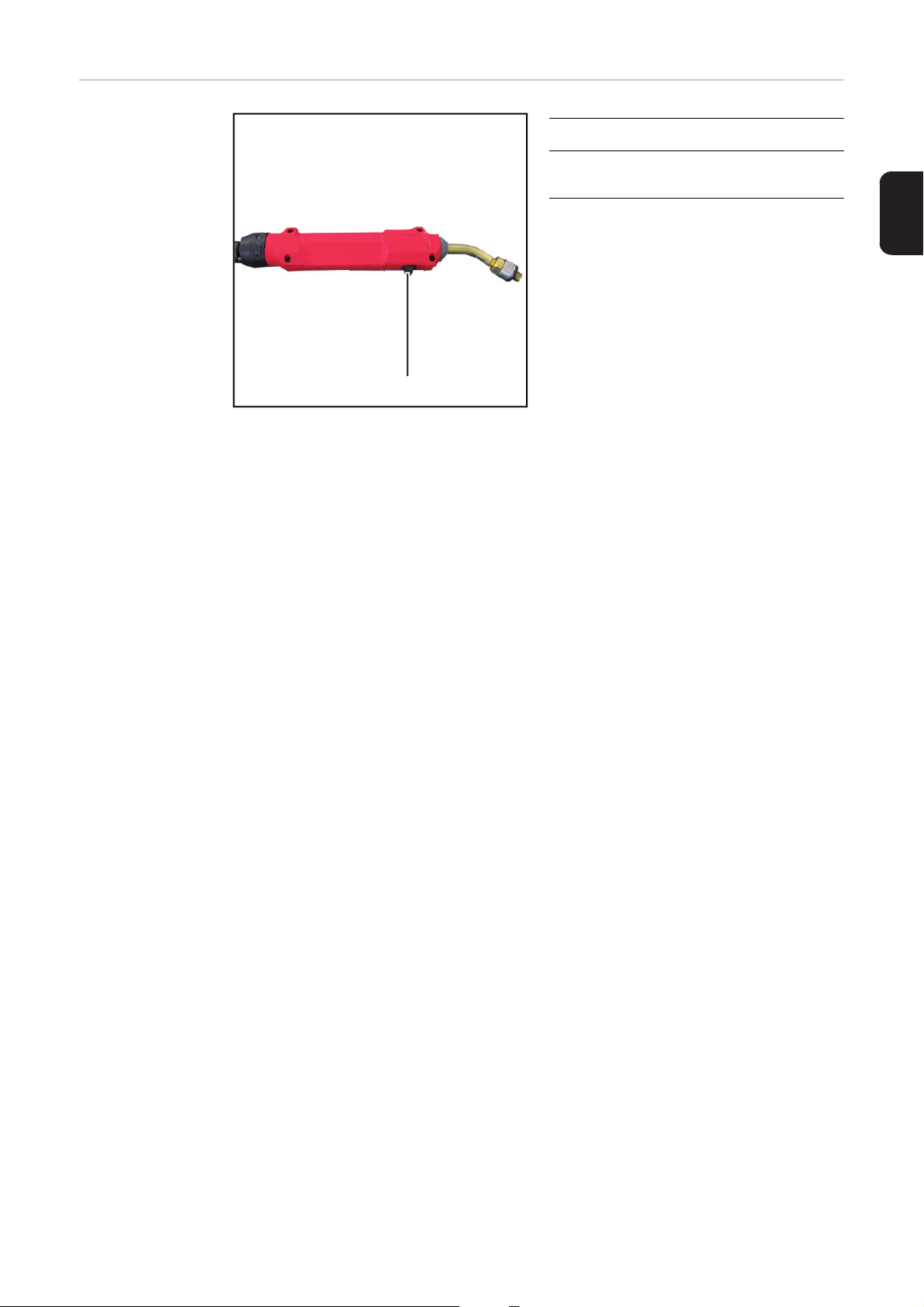
Push the adapter onto the gas plug (1)
1
as far as it will go
(1)
60
Page 63
Press and hold the flow button on the
(4)
(5)
2
adapter (2)
- The gas flow rate is measured
Note the value shown on the testbox
3
display and compare with the specified
gas flow rate
(2)
Release the flow button
4
- if the value is above or below the specified gas flow rate, check the welding torch
for damage
- if necessary, repair the welding torch
- repeat the gas flow test after the torch has been repaired
NOTE! For the specified gas flow rates, refer to the "Welding torch flow rates"
service test schedule (PP-SER-2001). The "Welding torch flow rates" service test
schedule (PP-SER-2001) is available from the DownloadCenter.
EN
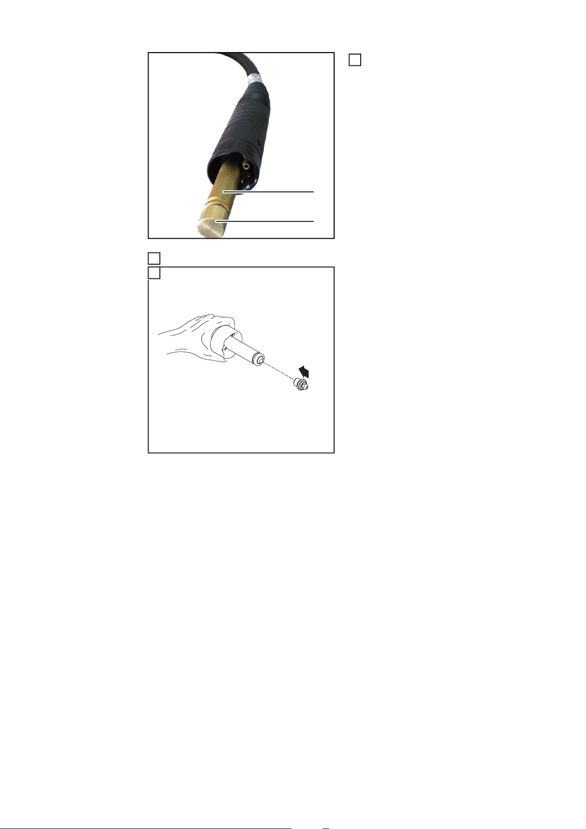
And finally... Only carry out the steps described below on gas-cooled welding torches:
Unscrew the FSC power pin cover (4)
1
from the power pin (5)
61
Page 64

Fit the inner liner in accordance with the welding torch operating instructions
2
3
1
62
Page 65

Checking gas flow rate on TPSi series MIG/MAG
3
welding torches with FSC torch connector
Safety
Preparations
WARNING! Work that is carried out incorrectly can cause serious injury and dam-
age. The work described below must only be carried out by Fronius-trained qualified personnel!
Place the O-ring (2) on the adapter (1)
1
as shown
(2)(1)
Screw the FSC attachment (3) onto the
2
adapter
Start the testbox
Turn the welding torch category switch
4
to the - MIG/MAG - position
EN
(3)
63
Page 66

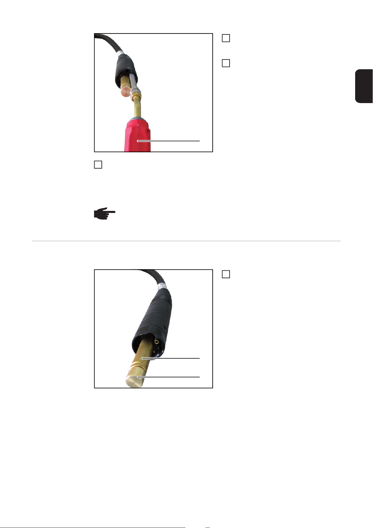
Only carry out the three steps described below on gas-cooled welding torches:
7
5
1
Remove the inner liner from the welding torch
6
Screw the FSC-G TPSi power pin cover (4) into the power pin (5) of the welding torch under test
Checking the gas
flow rate
(5)
(4)
NOTE! During the test:
- lay the adapter hosepack in a straight line from the testbox to the welding
torch
- place the welding torch on a suitable base so it is in a straight line
Push the adapter onto the gas plug (1)
1
as far as it will go
(1)
64
Page 67

Press and hold the flow button on the
(4)
(5)
2
adapter (2)
- The gas flow rate is measured
Note the value shown on the testbox
3
display and compare with the specified
gas flow rate
(2)
Release the flow button
4
- if the value is above or below the specified gas flow rate, check the welding torch
for damage
- if necessary, repair the welding torch
- repeat the gas flow test after the torch has been repaired
NOTE! For the specified gas flow rates, refer to the "Welding torch flow rates"
service test schedule (PP-SER-2001). The "Welding torch flow rates" service test
schedule (PP-SER-2001) is available from the DownloadCenter.
EN
And finally... Only carry out the steps described below on gas-cooled welding torches:
Unscrew the FSC-G TPSi power pin
1
cover (4) from the power pin (5)
65
Page 68

Fit the inner liner in accordance with the welding torch operating instructions
2
3
1
66
Page 69

Checking gas flow rate on MIG/MAG welding torches
3
with F++ torch connector
Safety
Preparations
WARNING! Work that is carried out incorrectly can cause serious injury and dam-
age. The work described below must only be carried out by Fronius-trained qualified personnel!
Place the O-ring (2) on the adapter (1)
1
as shown
(2)(1)
Screw the F-ZA / TIG-EC attachment
2
(3) onto the adapter
Start the testbox
Turn the welding torch category switch
4
to the - MIG/MAG - position
EN
(3)
Checking the gas
flow rate
NOTE! During the test:
- lay the adapter hosepack in a straight line from the testbox to the welding
torch
- place the welding torch on a suitable base so it is in a straight line
67
Page 70

(1)
(2)
Push the adapter into the gas hole (1)
1
as far as it will go
Press and hold the flow button on the
2
adapter (2)
- The gas flow rate is measured
Note the value shown on the testbox
3
display and compare with the specified
gas flow rate
Release the flow button
4
- if the value is above or below the specified gas flow rate, check the welding torch
for damage
- if necessary, repair the welding torch
- repeat the gas flow test after the torch has been repaired
NOTE! For the specified gas flow rates, refer to the "Welding torch flow rates"
service test schedule (PP-SER-2001). The "Welding torch flow rates" service test
schedule (PP-SER-2001) is available from the DownloadCenter.
68
Page 71

Checking gas flow rate on MIG/MAG welding torches
(3)
3
with Euro torch connector
Safety
Preparations
WARNING! Work that is carried out incorrectly can cause serious injury and dam-
age. The work described below must only be carried out by Fronius-trained qualified personnel!
Place the O-ring (2) on the adapter (1)
1
as shown
(2)(1)
Screw the EC attachment (3) onto the
2
adapter
Start the testbox
Turn the welding torch category switch
4
to the - MIG/MAG - position
EN
Checking the gas
flow rate
NOTE! During the test:
- lay the adapter hosepack in a straight line from the testbox to the welding
torch
- place the welding torch on a suitable base so it is in a straight line
69
Page 72

(1)
(2)
Push the adapter onto the gas plug (1)
1
as far as it will go
Press and hold the flow button on the
2
adapter (2)
- The gas flow rate is measured
Note the value shown on the testbox
3
display and compare with the specified
gas flow rate
Release the flow button
4
- if the value is above or below the specified gas flow rate, check the welding torch
for damage
- if necessary, repair the welding torch
- repeat the gas flow test after the torch has been repaired
NOTE! For the specified gas flow rates, refer to the "Welding torch flow rates"
service test schedule (PP-SER-2001). The "Welding torch flow rates" service test
schedule (PP-SER-2001) is available from the DownloadCenter.
70
Page 73
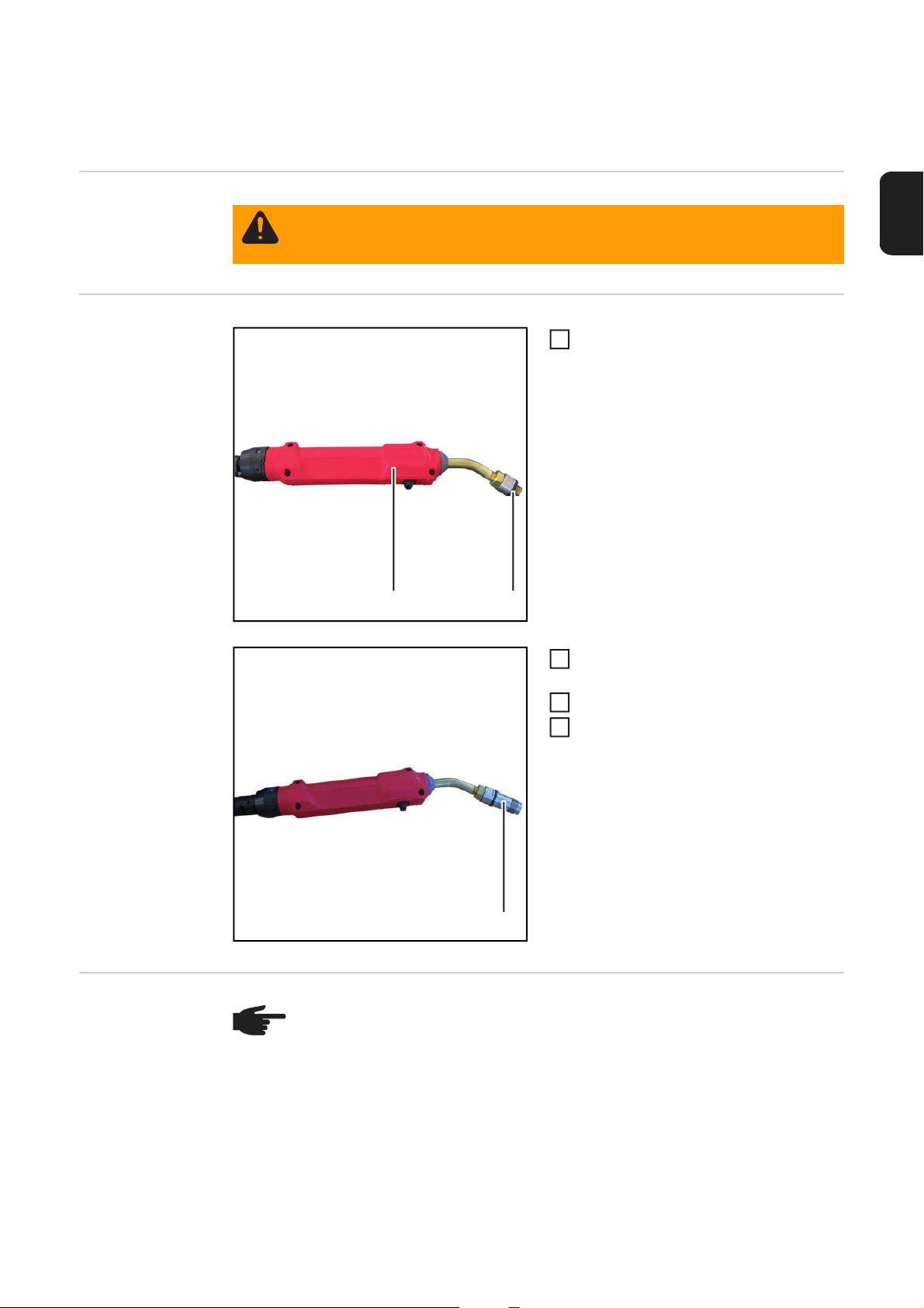
Checking gas flow rate on TIG welding torches with
3
a 1/4 inch gas connection
Safety
Preparations
WARNING! Work that is carried out incorrectly can cause serious injury and dam-
age. The work described below must only be carried out by Fronius-trained qualified personnel!
Place the O-ring (2) on the adapter (1)
1
as shown
(2)(1)
Screw the 1/4 TIG / PLASMA attach-
2
ment (3) onto the adapter
Start the testbox
Turn the welding torch category switch
4
to the - TIG - position
EN
(3)
Checking the gas
flow rate
NOTE! During the test:
- lay the adapter hosepack in a straight line from the testbox to the welding
torch
- place the welding torch on a suitable base so it is in a straight line
71
Page 74
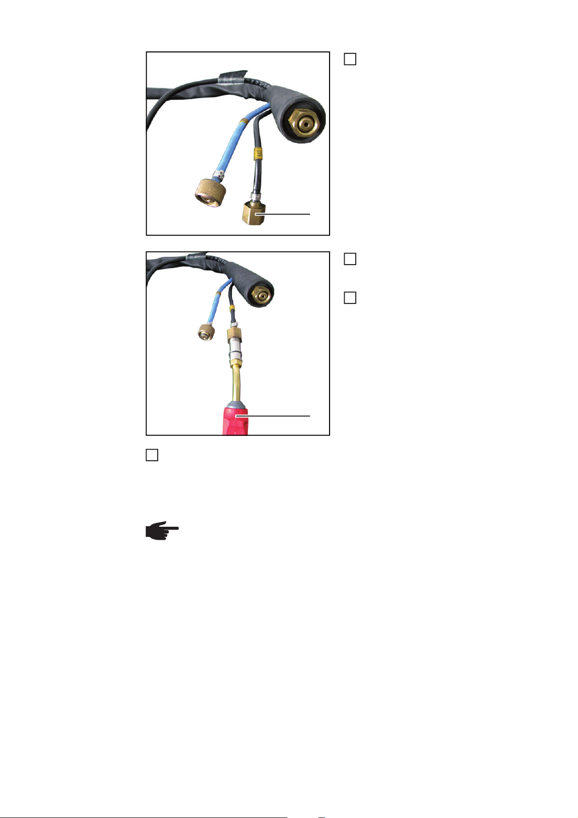
(1)
Screw the 'GAS' connection (1) onto
1
the 1/4 TIG / PLASMA attachment on
the adapter
Press and hold the flow button on the
2
adapter (2)
- The gas flow rate is measured
Note the value shown on the testbox
3
display and compare with the specified
gas flow rate
(2)
Release the flow button
4
- if the value is above or below the specified gas flow rate, check the welding torch
for damage
- if necessary, repair the welding torch
- repeat the gas flow test after the torch has been repaired
NOTE! For the specified gas flow rates, refer to the "Welding torch flow rates"
service test schedule (PP-SER-2001). The "Welding torch flow rates" service test
schedule (PP-SER-2001) is available from the DownloadCenter.
72
Page 75

Checking gas flow rate on TIG welding torches with
3
Euro torch connector
Safety
Preparations
WARNING! Work that is carried out incorrectly can cause serious injury and dam-
age. The work described below must only be carried out by Fronius-trained qualified personnel!
Place the O-ring (2) on the adapter (1)
1
as shown
(2)(1)
Screw the F-ZA / TIG-EC attachment
2
(3) onto the adapter
Start the testbox
Turn the welding torch category switch
4
to the - TIG - position
EN
(3)
Checking the gas
flow rate
NOTE! During the test:
- lay the adapter hosepack in a straight line from the testbox to the welding
torch
- place the welding torch on a suitable base so it is in a straight line
73
Page 76

(2)
(1)
Push the adapter into the gas hole (1)
1
as far as it will go
Press and hold the flow button on the
2
adapter (2)
- The gas flow rate is measured
Note the value shown on the testbox
3
display and compare with the specified
gas flow rate
Release the flow button
4
- if the value is above or below the specified gas flow rate, check the welding torch
for damage
- if necessary, repair the welding torch
- repeat the gas flow test after the torch has been repaired
NOTE! For the specified gas flow rates, refer to the "Welding torch flow rates"
service test schedule (PP-SER-2001). The "Welding torch flow rates" service test
schedule (PP-SER-2001) is available from the DownloadCenter.
74
Page 77
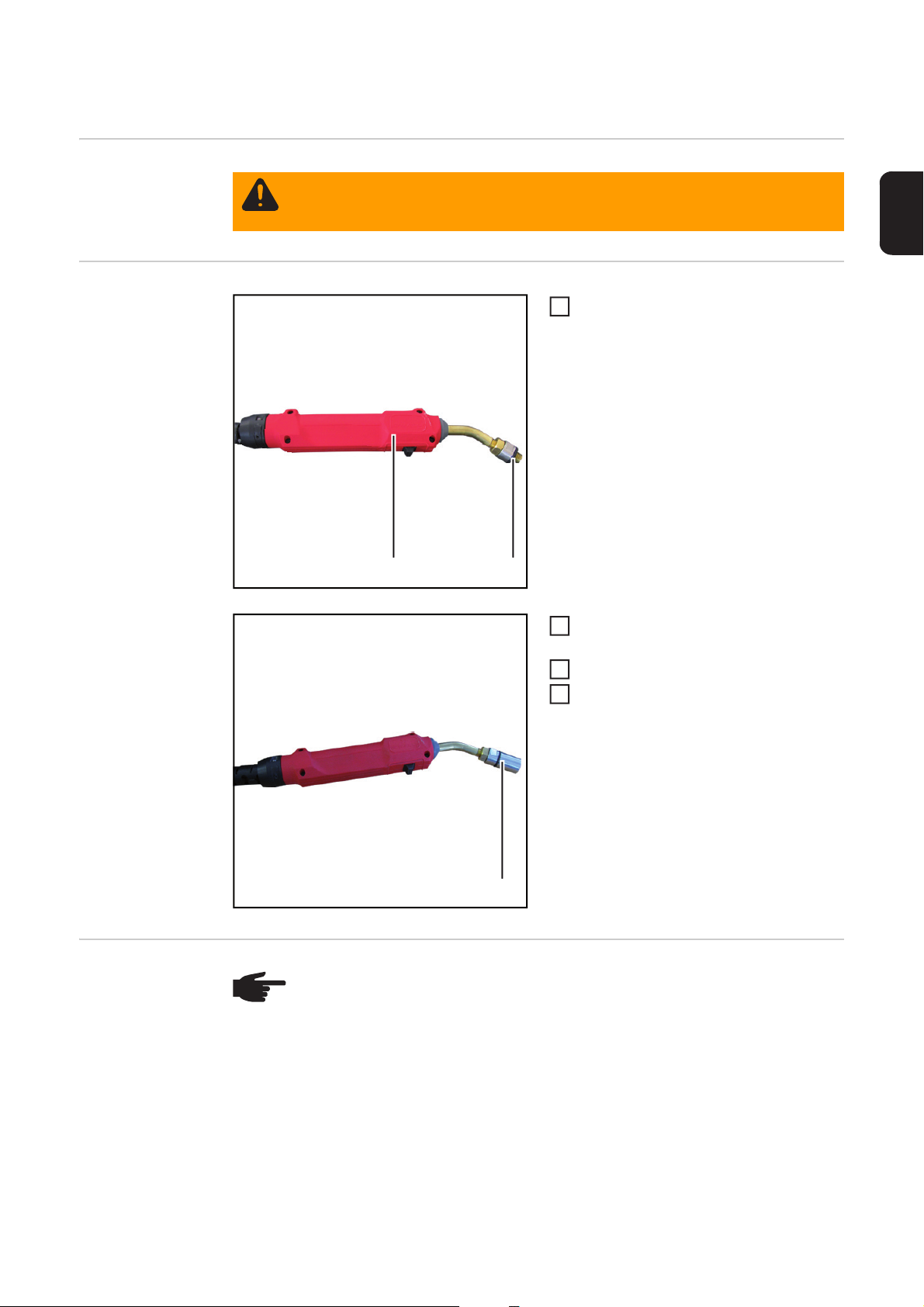
Checking gas flow rate on TTG/TTW welding torches
3
Safety
Preparations
WARNING! Work that is carried out incorrectly can cause serious injury and dam-
age. The work described below must only be carried out by Fronius-trained qualified personnel!
Place the O-ring (2) on the adapter (1)
1
as shown
(2)(1)
Screw TTG/TTW attachment (3) onto
2
the adapter
Start the testbox
Turn the welding torch category switch
4
to the - TIG - position
EN
(3)
Checking the gas
flow rate
NOTE! During the test:
- lay the adapter hosepack in a straight line from the testbox to the welding
torch
- place the welding torch on a suitable base so it is in a straight line
75
Page 78
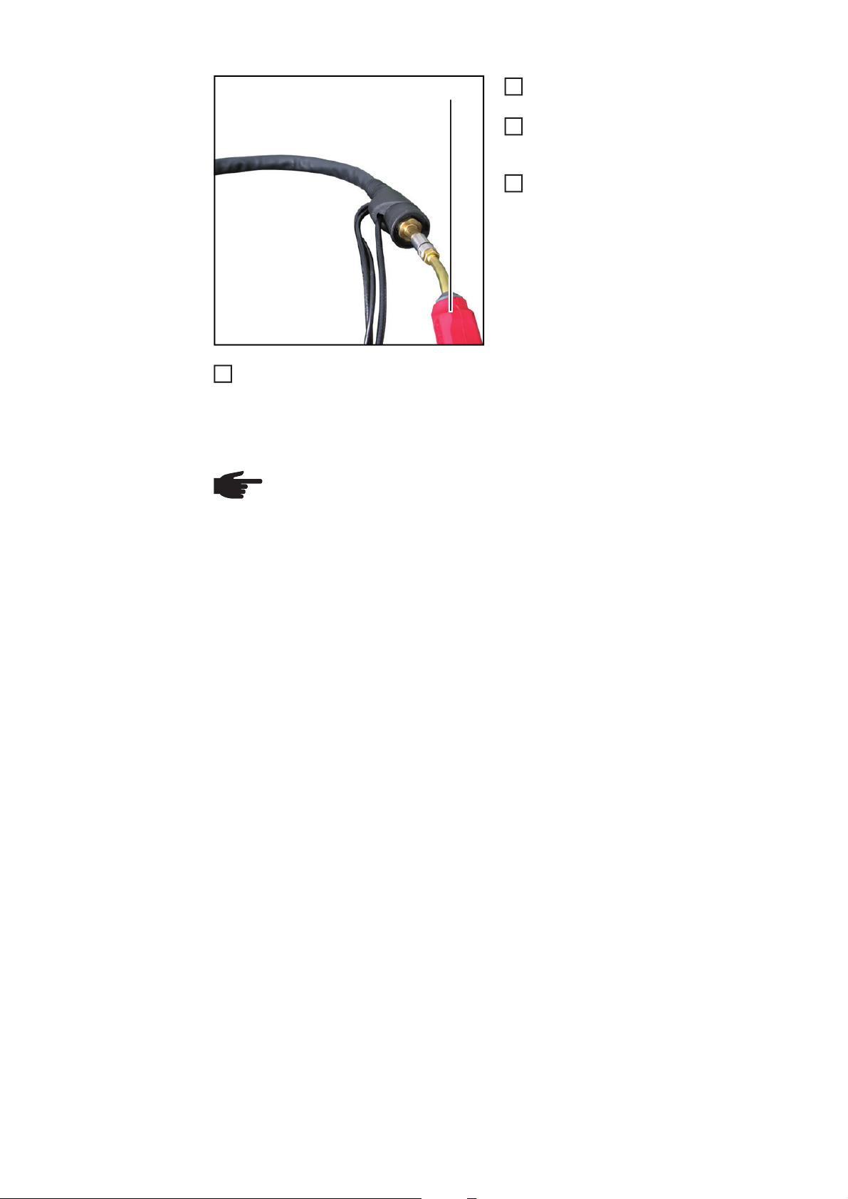
Push adapter (1) as far as it will go onto
3
(1)
Release the flow button
4
- if the value is above or below the specified gas flow rate, check the welding torch
for damage
- if necessary, repair the welding torch
- repeat the gas flow test after the torch has been repaired
NOTE! For the specified gas flow rates, refer to the "Welding torch flow rates"
service test schedule (PP-SER-2001). The "Welding torch flow rates" service test
schedule (PP-SER-2001) is available from the DownloadCenter.
1
the hosepack as shown
Press and hold the flow button on the
2
adapter
- The gas flow rate is measured
Note the value shown on the testbox
display and compare with the specified
gas flow rate
76
Page 79
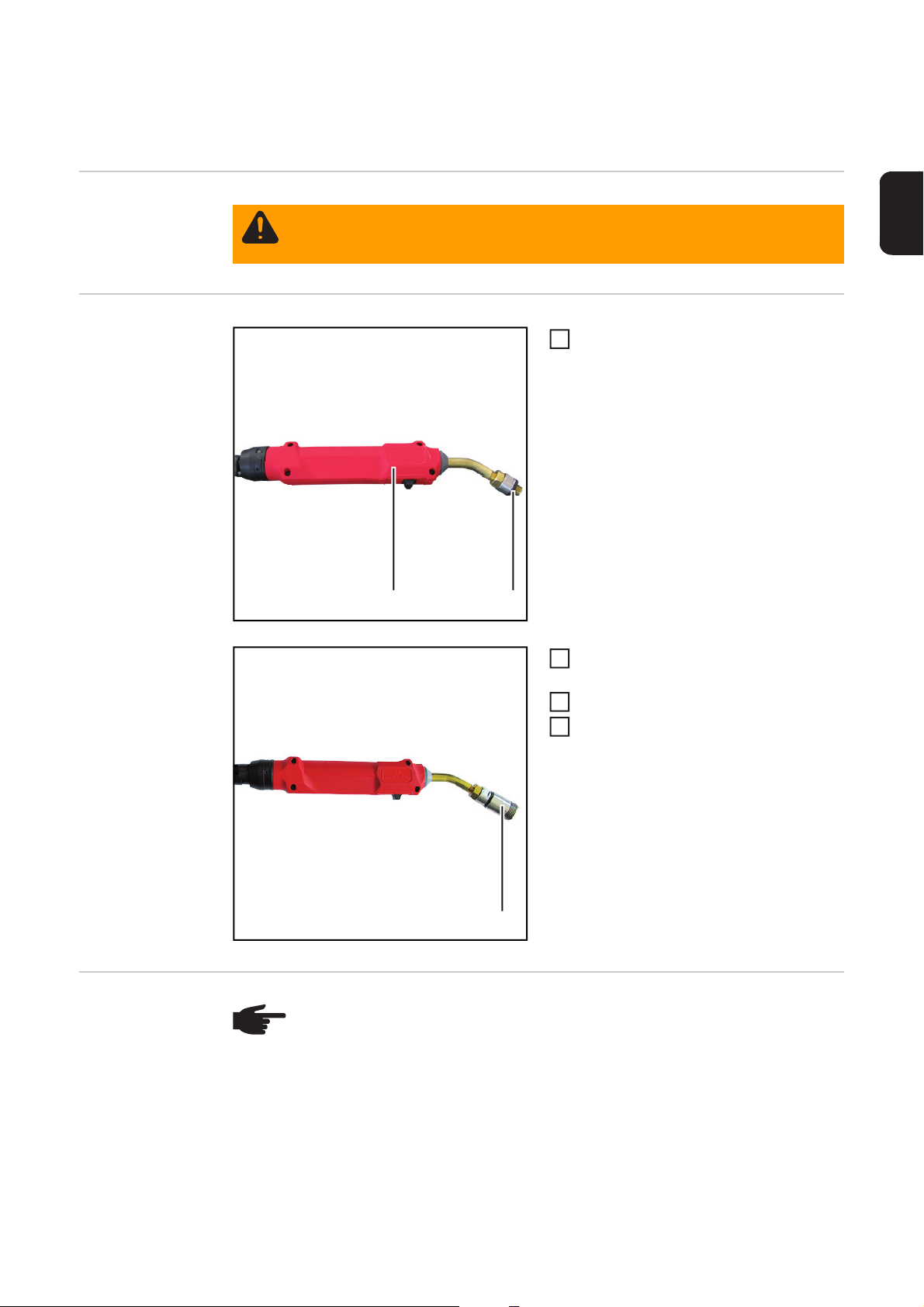
Checking gas flow rate on AL/PL 10/16/22-1/27-1
3
welding torches
Safety
Preparations
WARNING! Work that is carried out incorrectly can cause serious injury and dam-
age. The work described below must only be carried out by Fronius-trained qualified personnel!
Place the O-ring (2) on the adapter (1)
1
as shown
(2)(1)
Screw the 3/8 TIG / PLASMA attach-
2
ment (3) onto the adapter
Start the testbox
Turn the welding torch category switch
4
to the - TIG - position
EN
(3)
Checking the gas
flow rate
NOTE! During the test:
- lay the adapter hosepack in a straight line from the testbox to the welding
torch
- place the welding torch on a suitable base so it is in a straight line
77
Page 80

Screw the welding torch connection (1)
(2)
(1)
3
1
onto the 3/8 TIG / PLASMA attachment
on the adapter (2)
Press and hold the flow button on the
2
adapter (2)
- The gas flow rate is measured
Note the value shown on the testbox
display and compare with the specified
gas flow rate
Release the flow button
4
- if the value is above or below the specified gas flow rate, check the welding torch
for damage
- if necessary, repair the welding torch
- repeat the gas flow test after the torch has been repaired
NOTE! For the specified gas flow rates, refer to the "Welding torch flow rates"
service test schedule (PP-SER-2001). The "Welding torch flow rates" service test
schedule (PP-SER-2001) is available from the DownloadCenter.
78
Page 81

Checking plasma gas flow rate on PTW welding
3
torches with F++ torch connector
Safety
Preparations
WARNING! Work that is carried out incorrectly can cause serious injury and dam-
age. The work described below must only be carried out by Fronius-trained qualified personnel!
Place the O-ring (2) on the adapter (1)
1
as shown
(2)(1)
Screw the 1/4 TIG / PLASMA attach-
2
ment (3) onto the adapter
Start the testbox
Turn the welding torch category switch
4
to the - TIG - position
EN
(3)
Checking the
plasma gas flow
rate
NOTE! During the test:
- lay the adapter hosepack in a straight line from the testbox to the welding
torch
- place the welding torch on a suitable base so it is in a straight line
79
Page 82

Push adapter (1) as far as it will go onto
3
1
the bayonet latch (2) as shown
Press and hold the flow button on the
2
adapter
- The flow rate is measured
Note the value shown on the testbox
display and compare with the specified
(2)
flow rate
(1)
Release the flow button
4
- if the value is above or below the specified flow rate, check the welding torch for
damage
- if necessary, repair the welding torch
- repeat the flow test after the torch has been repaired
NOTE! For the specified gas flow rates, refer to the "Welding torch flow rates"
service test schedule (PP-SER-2001). The "Welding torch flow rates" service test
schedule (PP-SER-2001) is available from the DownloadCenter.
80
Page 83

Checking gas flow rate on PTW-Z welding torches
3
Safety
Preparations
WARNING! Work that is carried out incorrectly can cause serious injury and dam-
age. The work described below must only be carried out by Fronius-trained qualified personnel!
Place the O-ring (2) on the adapter (1)
1
as shown
(2)(1)
Screw the PTW-Z attachment (3) onto
2
the adapter
Start the testbox
Turn the welding torch category switch
4
to the - TIG - position
EN
(3)
Checking the gas
flow rate
NOTE! During the test:
- lay the adapter hosepack in a straight line from the testbox to the welding
torch
- place the welding torch on a suitable base so it is in a straight line
81
Page 84

Push the gas hose (1) of the hosepack
3
(2) (1)
Release the flow button
4
- if the value is above or below the specified flow rate, check the welding torch for
damage
- if necessary, repair the welding torch
- repeat the flow test after the torch has been repaired
NOTE! For the specified gas flow rates, refer to the "Welding torch flow rates"
service test schedule (PP-SER-2001). The "Welding torch flow rates" service test
schedule (PP-SER-2001) is available from the DownloadCenter.
1
into the adapter attachment (2) as
shown
Press and hold the flow button on the
2
adapter
- The flow rate is measured
Note the value shown on the testbox
display and compare with the specified
flow rate
82
Page 85

Checking plasma gas flow rate on PTW-Z welding
3
torches
Safety
Preparations
WARNING! Work that is carried out incorrectly can cause serious injury and dam-
age. The work described below must only be carried out by Fronius-trained qualified personnel!
Place the O-ring (2) on the adapter (1)
1
as shown
(2)(1)
Screw the 1/4 TIG / PLASMA attach-
2
ment (3) onto the adapter
Start the testbox
Turn the welding torch category switch
4
to the - TIG - position
EN
(3)
Checking the
plasma gas flow
rate
NOTE! During the test:
- lay the adapter hosepack in a straight line from the testbox to the welding
torch
- place the welding torch on a suitable base so it is in a straight line
83
Page 86

Screw the plasma gas hose (1) of the
3
1
hosepack onto the adapter attachment
(2)
Press and hold the flow button on the
2
adapter
- The flow rate is measured
Note the value shown on the testbox
(1)
(2)
Release the flow button
4
- if the value is above or below the specified flow rate, check the welding torch for
damage
- if necessary, repair the welding torch
- repeat the flow test after the torch has been repaired
NOTE! For the specified gas flow rates, refer to the "Welding torch flow rates"
service test schedule (PP-SER-2001). The "Welding torch flow rates" service test
schedule (PP-SER-2001) is available from the DownloadCenter.
display and compare with the specified
flow rate
84
Page 87

Care, maintenance and disposal
Safety
WARNING! Work that is carried out incorrectly can cause serious injury and dam-
age. All activities described in the operating instructions may only be carried out
by trained and qualified personnel. Personnel carrying out these activities must
have received training from Fronius in the correct operation of the device. Do not
carry out the work described until you have fully read and understood the following documents:
- these operating instructions
- all the operating instructions for the system components, especially the safe-
ty rules
WARNING! An electric shock can be fatal. Before starting work:
- Switch the device mains switch to the "O" position
- Unplug the device from the mains
- Ensure that the device remains disconnected from the mains until all work
has been completed
- Disconnect the device from the compressed air supply
- Ensure that the device remains disconnected from the compressed air sup-
ply until all work has been completed
After opening the device, use a suitable measuring instrument to check that electrically charged components (e.g. capacitors) have been discharged.
WARNING! An inadequate ground conductor connection can cause serious injury or damage. The housing screws provide a suitable ground conductor connection for earthing the housing and must NOT be replaced by any other screws that
do not provide a reliable ground conductor connection.
EN
On every start-up - Ensure that the mains plug and the mains cable are undamaged
- Ensure that the adapter hosepack is undamaged
- Ensure that the testbox compressed air hose is undamaged
Every 6 months:
Calibrate the testbox every 6 months as follows:
Calibrating the
testbox
NOTE! The serial number (1) on
the serial number attachment
must correspond to the serial
number (2) on the testbox.
A-4600Wels
www.fronius.com
1~
50/60 Hz
Mod.:
Part No. : 4,078,016
Ser. No.:
EN 61010-1
U
1
115/230 VAC
L x W x H
330mmx235mmx220mm
2011
Testbox - Torch Flow Rate
01234567
P
max in
I
1
0,3A
bar
10
(1)
(2)
0,8 A
IP 20
85
Page 88

Lay the adapter hosepack in a straight
4
1
line
Place the O-ring (3) on the adapter (4)
2
as shown
(3)(4)
Screw the serial number attachment
3
(1) onto the adapter
Start the testbox
Turn the welding torch category switch
5
to the - MIG/MAG - position
Press and hold the flow button on the
6
adapter (4)
- The flow rate is measured
- the actual value is shown on the
testbox display
(1)(4)
Compare the value shown with the specifications for the MIG/MAG welding torch cat-
7
egory on the calibration certificate - see (5) on the image below
- if the value matches the specifications on the calibration certificate, the testbox is
OK
- if the value does not match the specifications on the calibration certificate, send
the testbox to the manufacturer to be repaired
Release the flow button on the adapter
8
Turn the welding torch category switch to the - TIG - position
9
Press and hold the flow button on the adapter (2)
10
- The flow rate is measured
- the actual value is shown on the testbox display
Compare the value shown with the specifications for the TIG welding torch category
11
11
on the calibration certificate - see (6) on the image below
- if the value matches the specifications on the calibration certificate, the testbox is
OK
- if the value does not match the specifications on the calibration certificate, send
the testbox to the manufacturer to be repaired
Release the flow button
12
86
Page 89

EN
(5)
(6)
Every 6 months:
Checking that the
fan is working
correctly
Every 24 months
Disposal Dispose of in accordance with the applicable national and local regulations.
Check that the fan is working - as the fan extracts warm air from inside the device, you
should be able to feel the air flow it creates with your hand.
NOTE! Risk of damage to electronic components. Do not bring the air nozzle too
close to electronic components.
Remove the cover from the device and blow the inside clean with dry reduced compressed
air.
87
Page 90
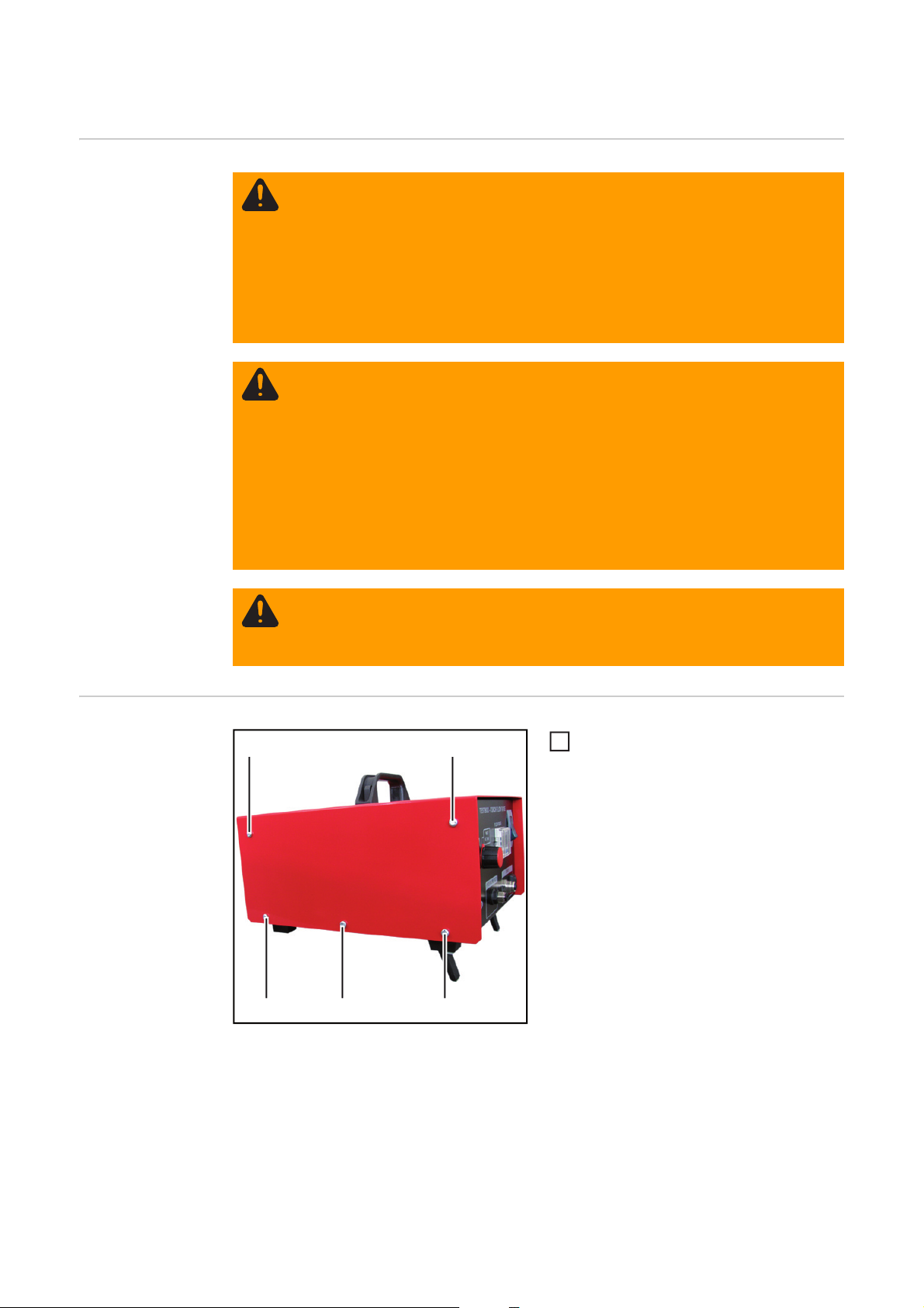
Changing the fan
Safety
WARNING! Work that is carried out incorrectly can cause serious injury and dam-
age. All activities described in the operating instructions may only be carried out
by trained and qualified personnel. Personnel carrying out these activities must
have received training from Fronius in the correct operation of the device. Do not
carry out the work described until you have fully read and understood the following documents:
- these operating instructions
- all the operating instructions for the system components, especially the safe-
ty rules
WARNING! An electric shock can be fatal. Before starting work:
- Switch the device mains switch to the "O" position
- Unplug the device from the mains
- Ensure that the device remains disconnected from the mains until all work
has been completed
- Disconnect the device from the compressed air supply
- Ensure that the device remains disconnected from the compressed air sup-
ply until all work has been completed
After opening the device, use a suitable measuring instrument to check that electrically charged components (e.g. capacitors) have been discharged.
WARNING! An inadequate ground conductor connection can cause serious injury or damage. The housing screws provide a suitable ground conductor connection for earthing the housing and must NOT be replaced by any other screws that
do not provide a reliable ground conductor connection.
Changing the fan
(1)
Undo the screws (1)
(1)
(1)(1)
(1)
1
88
Page 91
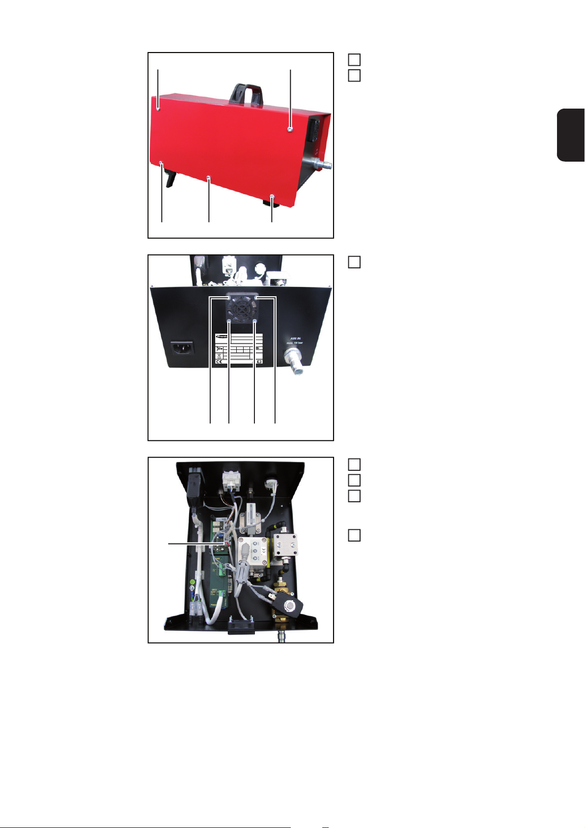
(2)
5
(2)
Undo the screws (2)
2
Remove the housing cover
3
EN
(4)
(2)(2)
(3)
A-4600Wels
www.fronius.com
1~
50/60 Hz
Mod.:
Part No. : 4,078,016
Ser. No.:
EN 61010-1
U
1
115/230 VAC
L x W x H
330mmx235mmx220mm
Testbox - Torch Flow Rate
P
max in
I
1
0,3A
10
2011
(2)
Undo the screws (3)
4
bar
0,8 A
IP 20
(3)(3)(3)
Unplug the connector (4)
Take out the fan
6
Insert the new fan into the housing, se-
7
cure it using the screws (3) and connect it in the testbox
Place the housing cover onto the test-
8
box and secure it using the screws (1)
and (2)
89
Page 92

Technical data
Torch Flow Rate
testbox
Mains voltage 1 (U
Grid frequency 50/60 Hz
Nominal pressure 10 bar
Mains fuse 0.8 A
Nominal current 0.3 A
Dimensions l x w x h 330 x 235 x 220
Protection class IP 20
Mark of conformity CE
) 115 V - 230 V
1
145.04 psi
12.99 x 9.52 x 8.66 in.
90
Page 93

Spare parts
(2)
(3)
(4)
(5)
(6)
(7)
(8)
(9)
(10)
(12)
(13)
(14)
(11)
Replacement
parts
(1) Adapter (43,0001,3357)
EN
(1)
(2) O-ring (42,0402,0009)
(3) FSC power pin cover
(42,0001,6438)
Suitable O-ring (42,0402,0083)
(4) TTG/TTW attachment
(42,0001,0026)
(5) F-ZA /TIG-EC attachment
(42,0001,0029)
Suitable O-ring (42,0402,0153)
(6) Push In attachment (42,0001,0024)
Suitable O-ring (42,0402,0153)
(7) 1/4 TIG / PLASMA attachment
(42,0001,0027)
(8) EC attachment (42,0001,0028)
(9) FSC attachment (42,0001,0025)
(10) 3/8 TIG / PLASMA attachment
(42,0001,4471)
(11) Coupling (44,0001,1145)
(12) O-ring (42,0001,0236)
(13) PTW-Z attachment (42,0001,4470)
(14) FSC-G TPSi power pin cover
(42,0001,4521)
Suitable O-ring (42,0300,2719)
91
Page 94

A-4600Wels
www.fronius.com
1~
50/60 Hz
(15)
Testbox - Torch Flow Rate
Mod.:
Part No. : 4,078,016
Ser. No.:
EN 61010-1
U
1
0,3A
115/230 VAC
L x W x H
330mmx235mmx220mm
2011
(15) Fan for testbox (43,0001,3356)
P
max in
I
1
bar
0,8 A
10
IP 20
92
Page 95

EN
93
Page 96

FRONIUS INTERNATIONAL GMBH
Froniusplatz 1, A-4600 Wels, Austria
Tel: +43 (0)7242 241-0, Fax: +43 (0)7242 241-3940
Under http://www.fronius.com/addresses you will find all addresses
of our Sales & service partners and Locations
E-Mail: sales@fronius.com
www.fronius.com
www.fronius.com/addresses
 Loading...