

Page 1

/ Battery Charging Systems / Welding Technology / Solar Electronics
DE
EN
Testbox CMT-Encoder
CMT encoder testbox
Bedienungsanleitung
Systemerweiterung
Operating Instructions
System extension
42,0410,1686 009-27112013
Page 2

0
Page 3

Sehr geehrter Leser
Einleitung Wir danken Ihnen für Ihr entgegengebrachtes Vertrauen und gratulieren Ihnen zu Ihrem
technisch hochwertigen Fronius Produkt. Die vorliegende Anleitung hilft Ihnen, sich mit
diesem vertraut zu machen. Indem Sie die Anleitung sorgfältig lesen, lernen Sie die vielfältigen Möglichkeiten Ihres Fronius-Produktes kennen. Nur so können Sie seine Vorteile
bestmöglich nutzen.
Bitte beachten Sie auch die Sicherheitsvorschriften und sorgen Sie so für mehr Sicherheit
am Einsatzort des Produktes. Sorgfältiger Umgang mit Ihrem Produkt unterstützt dessen
langlebige Qualität und Zuverlässigkeit. Das sind wesentliche Voraussetzungen für hervorragende Ergebnisse.
DE
1
Page 4

2
Page 5

Inhaltsverzeichnis
Allgemeines ............................................................................................................................................... 5
Gerätekonzept ...................................................................................................................................... 5
Lieferumfang......................................................................................................................................... 5
Hinweis für Reparatur- und Einstellarbeiten ......................................................................................... 5
Erforderliche Hilfsmittel ......................................................................................................................... 5
Warnhinweise am Gerät ....................................................................................................................... 5
Netzanschluss....................................................................................................................................... 6
Sicherheit.............................................................................................................................................. 6
Bedienelemente und Anschlüsse............................................................................................................... 8
Bedienelemente und Anschlüsse.......................................................................................................... 8
Display .................................................................................................................................................. 9
Encoder austauschen ................................................................................................................................ 10
Antriebseinheit vorbereiten .................................................................................................................. 10
Encoder ausbauen................................................................................................................................ 11
Encoder einbauen................................................................................................................................. 11
Encoder einstellen ..................................................................................................................................... 12
Testbox mit Antriebseinheit verbinden.................................................................................................. 12
Encoder einstellen ................................................................................................................................ 12
Encoder überprüfen ................................................................................................................................... 14
Einstellung des Encoders überprüfen ................................................................................................... 14
Encoder auf Indexprellen überprüfen.................................................................................................... 14
Abschließende Tätigkeiten......................................................................................................................... 15
Antriebseinheit zusammenbauen......................................................................................................... 15
Pflege, Wartung und Entsorgung............................................................................................................... 17
Sicherheit.............................................................................................................................................. 17
Bei jeder Inbetriebnahme...................................................................................................................... 17
Alle 6 Monate........................................................................................................................................ 17
Entsorgung............................................................................................................................................ 17
Prüfdokumentation..................................................................................................................................... 18
Prüfdokumentation................................................................................................................................ 18
Technische Daten ...................................................................................................................................... 19
Testbox CMT-Encoder.......................................................................................................................... 19
DE
3
Page 6

4
Page 7

Allgemeines
Gerätekonzept Die Testbox CMT-Encoder dient zum:
- Testen des Encoders der Robacta
Drive CMT-Antriebseinheit
- Einstellen des Encoders der Robacta
Drive CMT-Antriebseinheit nach Austausch des Encoders
DE
Lieferumfang
Hinweis für Reparatur- und Einstellarbeiten
(1) Testbox CMT-Encoder
(1)
(3) (4)
HINWEIS! Für Reparatur- und Einstellarbeiten die nicht vom Hersteller durchgeführt wurden können keine Garantieansprüche geltend gemacht werden.
(2)
(2) Adapter MOTOR (Artikelnummer
43,0004,2713)
(3) Netzkabel
(4) Adapter ENCODER (Artikelnum-
mer 43,0004,4303)
(5) Bedienungsanleitung (nicht abge-
bildet)
Erforderliche
Hilfsmittel
Warnhinweise am
Gerät
- Loctite 243
Das Gerät ist mit Sicherheitssymbolen am Leistungsschild ausgestattet. Die Sicherheitssymbole dürfen weder entfernt noch übermalt werden. Die Symbole warnen vor Fehlbedienung, woraus schwerwiegende Personen- und Sachschäden resultieren können.
5
Page 8

Type
A-4600 Wels
www.fronius.com
IEC 61010-1 / EN 61000-6-4 / -6-2
Art.No.
Ser.No.
Testbox CMT-Encoder
IP 20
1~
50-60Hz
U
1
230 V
I
1
0,8 A
Ausgediente Geräte nicht in den Hausmüll geben,
sondern entsprechend den Sicherheitsvorschriften entsorgen.
Funktionen erst nach vollständigem Lesen der
Bedienungsanleitung anwenden.
Netzanschluss Das Gerät ist für die am Leistungschild angegebene Netzspannung ausgelegt. Die erfor-
derliche Absicherung der Netzzuleitung finden Sie im Abschnitt „Technische Daten“. Sind
Netzkabel oder Netzstecker bei Ihrer Geräteausführung nicht angebracht, Netzkabel oder
Netzstecker entsprechend den nationalen Normen montieren.
HINWEIS! Nicht ausreichend dimensionierte Elektroinstallation kann zu schwerwiegenden Sachschäden führen. Die Netzzuteilung sowie deren Absicherung
sind entsprechend der vorhandenen Stromversorgung auszulegen. Es gelten die
Technischen Daten auf dem Leistungsschild.
Sicherheit
WARNUNG! Fehlbedienung und fehlerhaft durchgeführte Arbeiten können
schwerwiegende Personen- und Sachschäden verursachen. Alle in der Bedienungsanleitung beschriebenen Funktionen dürfen nur von geschultem Fachpersonal angewendet werden. Alle in der Bedienungsanleitung beschriebenen
Arbeiten dürfen nur von geschultem Fachpersonal durchgeführt werden. Das
Fachpersonal muss von der Fa. Fronius eine Schulung zur ordnungsgemäßen
Bedienung des Gerätes erhalten haben. Die beschriebenen Funktionen erst anwenden und die beschriebenen Arbeiten erst durchführen, wenn folgende Dokumente vollständig gelesen und verstanden wurden:
- diese Bedienungsanleitung
- sämtliche Bedienungsanleitungen der Systemkomponenten, insbesondere
Sicherheitsvorschriften
WARNUNG! Fehlerhaft durchgeführte Arbeiten können schwerwiegende Sachund Personenschäden verursachen. Vor allen Arbeiten und Tests an der Robacta
Drive CMT Antriebseinheit:
- Netzschalter der Stromquelle in Stellung - O - schalten
- Stromquelle vom Netz trennen
- Sicherstellen, dass die Stromquelle bis zum Abschluss aller Arbeiten vomNetz getrennt bleibt
- Drahtelektrode aus dem Schlauchpaket entfernen
- die Robacta Drive CMT Antriebseinheit von allen Systemkomponenten trennen
6
Page 9

VORSICHT! Verbrennungsgefahr durch heiße Schweißbrenner-Komponenten
und heißes Kühlmittel. Vor Beginn aller in dieser Bedienungsanleitung beschriebenen Arbeiten sämtliche Schweißbrenner-Komponenten und das Kühlmittel auf
Zimmertemperatur (+25 °C, + 77 °F) abkühlen lassen.
VORSICHT! Bei wassergekühlten Schweißbrennern: Gefahr von Sachschäden
durch auslaufendes Kühlmittel. Vor Beginn aller in dieser Bedienungsanleitung
beschriebenen Arbeiten, das Kühlmittel aus dem Schweißbrenner entfernen.
DE
7
Page 10
Bedienelemente und Anschlüsse
(8)
(7)
Bedienelemente
und Anschlüsse
(2)
(1)
(4)(5)(6)
Vorderseite Testbox Rückseite Testbox
Nr. Funktion
(1) Kontroll-Leuchte MOTOR WINDING OK
leuchtet, wenn die Motorwicklungen der Antriebseinheit richtig bestromt werden
(2) Taste START
startet das Bestromen des Motors der Antriebseinheit
(3)
(3) Netzschalter
zum Ein- und Ausschalten der Testbox
(4) Anschluss ENCODER
zum Verbinden der Testbox mit dem Encoder der Antriebseinheit
(5) Anschluss MOTOR
zum Verbinden der Testbox mit dem Motor der Antriebseinheit
(6) Taste STOPP
beendet das Bestromen des Motors der Antriebseinheit
(7) Anschluss Netzkabel
(8) Anschluss Update
für Software-Updates
8
Page 11

Display
(1)
(2)
(3)
(4)(5)(6)
DE
Nr. Funktion
(1) Display
(2) LED L1, L2, K1 - K4
LED L1 blinkt, beim Einstellen des Encoders
LED L2 blinkt, beim Überprüfen des Encoders auf Indexprellen
LED K1 leuchtet, wenn ein Grenzwert im positiven Bereich überschritten wird
LED K2 leuchtet, wenn ein Grenzwert im negativen Bereich überschritten wird
LED K3 hat keine Funktion
LED K4 leuchtet, wenn der Index mehrmals gezählt wird (ein Index entspricht einer
ganzen Umdrehung der Rotorwelle)
(3) Taste ‘Enter‘
zum Bestätigen einer Auswahl
(4) Taste ‘Ab‘
zum Auswählen einer Funktion
(5) Taste ‘Auf‘
zum Auswählen einer Funktion
(6) Taste ‘P‘
hat keine Funktion
9
Page 12
Encoder austauschen
(1+2) (2)
5
Antriebseinheit
vorbereiten
(1+2)
(3)
(2)
2 Versiegelungen (1) durchstechen
1
4 Schrauben (2) lösen
2
Bodenplatte (3) mit leicht ruckenden
3
Bewegungen abnehmen
WICHTIG! Falls vorhanden, muss die
Flachdichtung am Motorgehäuse verbleiben.
Elektronik-Box nach hinten aus der Nut
4
ziehen
10
Stecker (4) von Print RDIO 30 A abstecken
(4)
Page 13
Encoder ausbau-
(1)
(4)
(3)
(4)
(5)
(2)
(2)
2
4
(2)
(4)
(4)
(3)
(1)
(1)
3
5
en
Stecker (1) von Encoder abziehen
1
Encoder-Klipp (2) herausziehen
Innensechskant-Schraube (3) lösen
3
Schrauben (4) lösen
Encoder (5) abziehen
5
DE
Encoder einbauen
Encoder-Klipp (1) herausziehen
1
Encoder (2) wie abgebildet auf An-
2
triebseinheit aufsetzen
Encoder-Scheibe (3) Richtung An-
triebseinheit drücken
- dadurch wird der Encoder zentriert
Schrauben (4) festschrauben, Anzugs-
4
moment = 0,2 Nm
Stecker (5) wie abgebildet anstecken
Encoder einstellen (siehe Kapitel „En-
6
coder einstellen“)
(5)
11
Page 14

Encoder einstellen
3
6
(3)
(3)
(2)(1)
2
4
Testbox mit Antriebseinheit verbinden
Adapter ENCODER an Anschluss EN-
1
CODER der Textbox anschließen und
festschrauben
Adapter ENCODER an Antriebseinheit
2
anschließen
Adapter MOTOR an Anschluss MOTOR der Testbox anschließen und
festschrauben
Adapter MOTOR wie abgebildet an
4
Elektronik-Box anschließen
Testbox an das Netz anschließen
5
Netzschalter der Testbox betätigen
Encoder einstellen
12
Innensechskant-Schraube (1) aus En-
1
coder-Scheibe (2) schrauben
Loctite 243 auf die Innensechskant-
Schraube geben
Innensechskant-Schraube wieder in
3
Encoder-Scheibe schrauben, aber
noch nicht festschrauben
Encoder-Scheibe (2) mittels Innensechskant-Schlüssel verdrehen,
bis das Display der Testbox einen Wert
größer als 0 zeigt
Encoder-Scheibe (2) mittels In-
5
nensechskant-Schlüssel zurückdrehen, bis das Display der Testbox 0
zeigt
Taste START an der Testbox drücken
6
- Motor der Antriebseinheit wird für
2 Minuten mit Strom versorgt
Page 15

Encoder-Scheibe (2) zur Antriebseinheit drücken und mittels Innensechskant-Schlüs-
10
11
11
7
sel verdrehen, bis das Display der Testbox 0 zeigt (Toleranz = +/- 15)
Encoder-Scheibe mittels Innensechskant-Schraube in dieser Position fixieren, An-
8
zugsmoment = 0,4 Nm
Taste ‘STOPP‘ an der Testbox drücken
9
- Stromversorgung des Motors der Antriebseinheit wird gestoppt
Encoder-Klipp (3) in Encoder reindrücken
Encoder überprüfen (siehe Kapitel „Encoder überprüfen“)
DE
13
Page 16

Encoder überprüfen
3
6
Einstellung des
Encoders überprüfen
Encoder auf Indexprellen überprüfen
(1)
(1)
Rotorwelle (1) verdrehen, bis das Dis-
1
play der Testbox 350 zeigt (Toleranz =
+/- 150)
Taste START an der Testbox drücken
2
- Motor der Antriebseinheit wird für
2 Minuten mit Strom versorgt
Angezeigten Wert am Display überprü-
3
fen
- bei einem Wert zwischen - 15 und
+ 15 ist die Einstellung des Encoders korrekt
- bei einem Wert außerhalb des angegebenen Bereiches, Encoder
einstellen
Taste ‘STOPP‘ an der Testbox drü-
4
cken
- Stromversorgung des Motors der
Antriebseinheit wird gestoppt
Encoder auf Indexprellen prüfen
5
Taste ‘Auf‘ an der Testbox drücken, bis
1
die LED L2 blinkt
Taste ‘Enter‘ an der Testbox drücken
2
- das Display der Testbox zeigt 0
Rotorwelle (1) verdrehen, bis das Display der Testbox 1 zeigt
Rotorwelle (1) um weitere 360° verdre-
4
hen, bis das Display der Testbox 2
zeigt
- der Index darf pro ganzer Umdrehung der Rotorwelle nur einmal
gezählt werden
- Wird der Index mehrmals pro ganzer Umdrehung der Rotorwelle
gezählt liegt ein Montageproblem
vor, Montageproblem beheben
- Leuchtet die LED K4 während einer Umdrehung der Rotorwelle
liegt ein Montageproblem vor,
Montageproblem beheben
Testbox ausschalten
5
Testbox von Netz trennen
14
Page 17

Abschließende Tätigkeiten
4
DE
Antriebseinheit
zusammenbauen
(1)
Stecker (1) an Print RDIO 30 A anste-
1
cken
Adapter ENCODER von Antriebsein-
2
heit abschließen
Adapter MOTOR von Elektronik-Box
3
abschließen
WICHTIG! Darauf achten, dass sich die
Moosgummi-Dichtung in der Nut für die
Elektronik-Box befindet.
Elektronik-Box auf Antriebseinheit aufsetzen
(2)
(2)
(2)
(2)
Bodenplatte aufsetzen
5
Bodenplatte mit 4 Schrauben (2) an
6
der Antriebseinheit festschrauben
- Schrauben diagonal festschrauben
- Anzugsmoment = 3 Nm
15
Page 18

(3) (3)
Nur bei werksseitigem Zusammenbau:
7
Die vorderen 2 Schrauben an der Bodenplatte mit Versiegelungsetiketten
(3) versiegeln
16
Page 19

Pflege, Wartung und Entsorgung
DE
Sicherheit
WARNUNG! Fehlerhaft durchgeführte Arbeiten können schwerwiegende Per-
sonen- und Sachschäden verursachen. Alle in der Bedienungsanleitung beschriebenen Arbeiten dürfen nur von geschultem Fachpersonal durchgeführt
werden. Das Fachpersonal muss von der Fa. Fronius eine Schulung zur ordnungsgemäßen Bedienung des Gerätes erhalten haben. Die beschriebenen Arbeiten erst durchführen, wenn folgende Dokumente vollständig gelesen und
verstanden wurden:
- diese Bedienungsanleitung
- sämtliche Bedienungsanleitungen der Systemkomponenten, insbesondere
Sicherheitsvorschriften
WARNUNG! Ein elektrischer Schlag kann tödlich sein. Vor Öffnen des Gerätes:
- Netzschalter des Gerätes in Stellung - O - schalten
- Gerät vom Netz trennen
- sicherstellen, dass das Gerät bis zum Abschluss aller Arbeiten vom Netz getrennt bleibt
Nach dem Öffnen des Gerätes mit Hilfe eines geeigneten Messgerätes sicherstellen, dass elektrisch geladene Bauteile (z.B. Kondensatoren) entladen sind.
WARNUNG! Unzureichende Schutzleiter-Verbindung kann schwerwiegende
Personen- und Sachschäden verursachen. Die Gehäuse-Schrauben stellen eine
geeignete Schutzleiter-Verbindung für die Erdung des Gehäuses dar und dürfen
keinesfalls durch andere Schrauben ohne zuverlässige Schutzleiter-Verbindung
ersetzt werden.
Bei jeder Inbetriebnahme
Alle 6 Monate
Entsorgung Die Entsorgung nur gemäß den geltenden nationalen und regionalen Bestimmungen
- Netzstecker und Netzkabel auf Beschädigung prüfen
- Adapterkabel auf Beschädigungen prüfen
HINWEIS! Gefahr der Beschädigung elektronischer Bauteile. Elektronische Bauteile nicht aus kurzer Entfernung anblasen.
- Geräte-Deckel demontieren und das Geräteinnere mit trockener, reduzierter Druckluft
sauberblasen
durchführen.
17
Page 20

Prüfdokumentation
Prüfdokumentation
Geprüftes Gerät
Gerät geprüft von
Prüfung durchgeführt am
Festgestellte Mängel
Zur Behebung der Mängel
getroffene Maßnahmen
Mängel behoben am
Geprüftes Gerät
Gerät geprüft von
Prüfung durchgeführt am
Festgestellte Mängel
Zur Behebung der Mängel
getroffene Maßnahmen
Mängel behoben am
Geprüftes Gerät
Gerät geprüft von
Prüfung durchgeführt am
Festgestellte Mängel
Zur Behebung der Mängel
getroffene Maßnahmen
Mängel behoben am
18
Page 21

Technische Daten
DE
Testbox CMT-Encoder
Netzspannung 1 (U
Netzfrequenz 50 / 60 Hz
Nennstrom 0,8 A
Schutzart IP 20
Prüfzeichen CE
) 100 V - 240 V
1
19
Page 22

20
Page 23

Dear reader,
Introduction Thank you for the trust you have placed in our company and congratulations on buying this
high-quality Fronius product. These instructions will help you familiarise yourself with the
product. Reading the instructions carefully will enable you to learn about the many different
features it has to offer. This will allow you to make full use of its advantages.
Please also note the safety rules to ensure greater safety when using the product. Careful
handling of the product will repay you with years of safe and reliable operation. These are
essential prerequisites for excellent results.
EN
21
Page 24

22
Page 25

Contents
General ...................................................................................................................................................... 25
Device concept ..................................................................................................................................... 25
Scope of supply .................................................................................................................................... 25
Information for repair and set up work .................................................................................................. 25
Material required................................................................................................................................... 25
Warning notices affixed to the device ................................................................................................... 25
Mains connection .................................................................................................................................. 26
Safety.................................................................................................................................................... 26
Control elements and connections............................................................................................................. 28
Control elements and connections........................................................................................................ 28
Display .................................................................................................................................................. 29
Replacing the encoder ............................................................................................................................... 30
Preparing the drive unit......................................................................................................................... 30
Removing the encoder.......................................................................................................................... 31
Fitting the encoder ................................................................................................................................ 31
Setting the encoder.................................................................................................................................... 32
Connecting the testbox to the drive unit................................................................................................ 32
Setting the encoder............................................................................................................................... 32
Checking the encoder ................................................................................................................................ 34
Checking the encoder settings.............................................................................................................. 34
Checking the encoder for index contact bounce...................................................................................34
Finally......................................................................................................................................................... 35
Reassemble the drive unit .................................................................................................................... 35
Care, maintenance and disposal ............................................................................................................... 37
Safety.................................................................................................................................................... 37
At every start-up.................................................................................................................................... 37
Every 6 months..................................................................................................................................... 37
Disposal ................................................................................................................................................ 37
Inspection documentation .......................................................................................................................... 38
Inspection documentation ..................................................................................................................... 38
Technical data............................................................................................................................................ 39
CMT encoder testbox............................................................................................................................ 39
EN
23
Page 26

24
Page 27

General
Device concept The CMT encoder testbox:
- Tests the encoder on the Robacta
Drive CMT unit
- Sets the parameters on the Robacta
Drive CMT unit encoder if it has been
replaced
EN
Scope of supply
Information for
repair and set up
work
(1) CMT encoder testbox
(1)
(3) (4)
NOTE! The warranty does not cover repair or set up work that was not carried out
by the manufacturer.
(2)
(2) MOTOR adapter (item number
43,0004,2713)
(3) Mains cable
(4) ENCODER adapter (item number
43,0004,4303)
(5) Operating instructions (not shown)
Material required - Loctite 243
Warning notices
affixed to the device
A number of safety symbols can be seen on the device's rating plate. The safety symbols
must NOT be removed or painted over. The symbols warn against operating the equipment
incorrectly, as this may result in serious injury and damage.
25
Page 28

Type
A-4600 Wels
www.fronius.com
IEC 61010-1 / EN 61000-6-4 / -6-2
IP 20
50-60Hz
Art.No.
Ser.No.
1~
Testbox CMT-Encoder
1
U
230 V
I
1
0,8 A
Do not dispose of used units with domestic waste.
Dispose of them according to safety rules.
Do not use the functions until you have fully read
all the operating instructions.
Mains connection The device is designed to run at the mains voltage indicated on the rating plate. The re-
quired fuse protection for the mains supply can be found in the "Technical data" section. If
there is no mains cable or mains plug on your device, fit one that conforms to national
standards.
Safety
NOTE! Inadequately dimensioned electrical installations can cause serious dam-
age. The incoming mains lead and its fuse must be dimensioned to suit the local
power supply. The technical data shown on the rating plate applies.
WARNING! Incorrect operation or shoddy workmanship can cause serious injury
or damage. All functions described in the operating instructions may only be used
by trained and qualified personnel. All activities described in the operating instructions may only be carried out by trained and qualified personnel. Personnel carrying out these activities must have received training from Fronius in the correct
operation of the device. Do not use any of the functions described or carry out the
work described until you have fully read and understood the following documents:
- these operating instructions
- all the operating instructions for the system components, especially the safety rules
WARNING! Work that is carried out incorrectly can cause serious injury and damage. Before working and performing tests on the Robacta Drive CMT unit:
- Turn the power source mains switch to the "O" position
- Disconnect the power source from the mains
- Ensure that the power source remains disconnected from the mains until all
work has been completed
- Remove the wire electrode from the hosepack
- Disconnect the Robacta Drive CMT unit from all system components
26
CAUTION! Risk of burns from hot welding torch components and hot coolant. Before commencing any of the work described in these operating instructions, allow
all welding torch components and the coolant to cool to room temperature (+25
°C, +77 °F).
Page 29

CAUTION! On water-cooled welding torches: Risk of damage due to escaping
coolant. Drain coolant from the welding torch before starting any of the work described in these operating instructions.
EN
27
Page 30

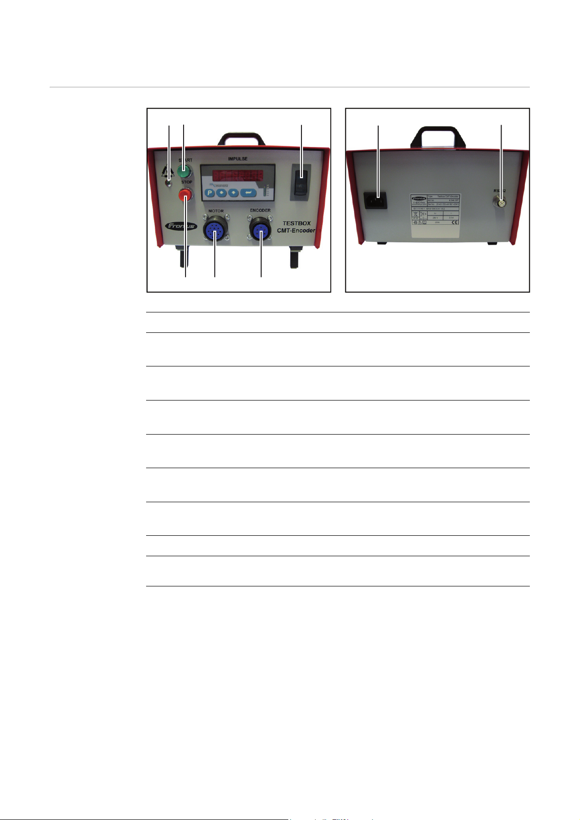
Control elements and connections
(8)
(7)
Control elements
and connections
(2)
(1)
(4)(5)(6)
Front of the testbox Rear of the testbox
No. Function
(1) 'MOTOR WINDING OK' indicator light
Lights up to indicate that the drive unit motor windings are being powered correctly
(2) START button
Switches the drive unit motor on
(3)
(3) Mains switch
Switches the testbox on and off
(4) ENCODER connection
For connecting the testbox to the drive unit encoder
(5) MOTOR connection
For connecting the testbox to the drive unit motor
(6) STOP button
Switches the drive unit motor off
(7) Mains cable connection
(8) Update connection
For software updates
28
Page 31

Display
(1)
(2)
(3)
(4)(5)(6)
EN
No. Function
(1) Display
(2) LED L1, L2, K1 - K4
LED L1 flashes when the encoder is being set
LED L2 flashes when checking the encoder for index contact bounce
LED K1 lights up when a positive limit value is exceeded
LED K2 lights up when a negative limit value is exceeded
LED K3 has no function
LED K4 lights up when the index is counted several times (an index equates to a
complete rotation of the rotor shaft)
(3) Enter key
To confirm a selection
(4) Down key
To select a function
(5) Up key
To select a function
(6) P key
Has no function
29
Page 32

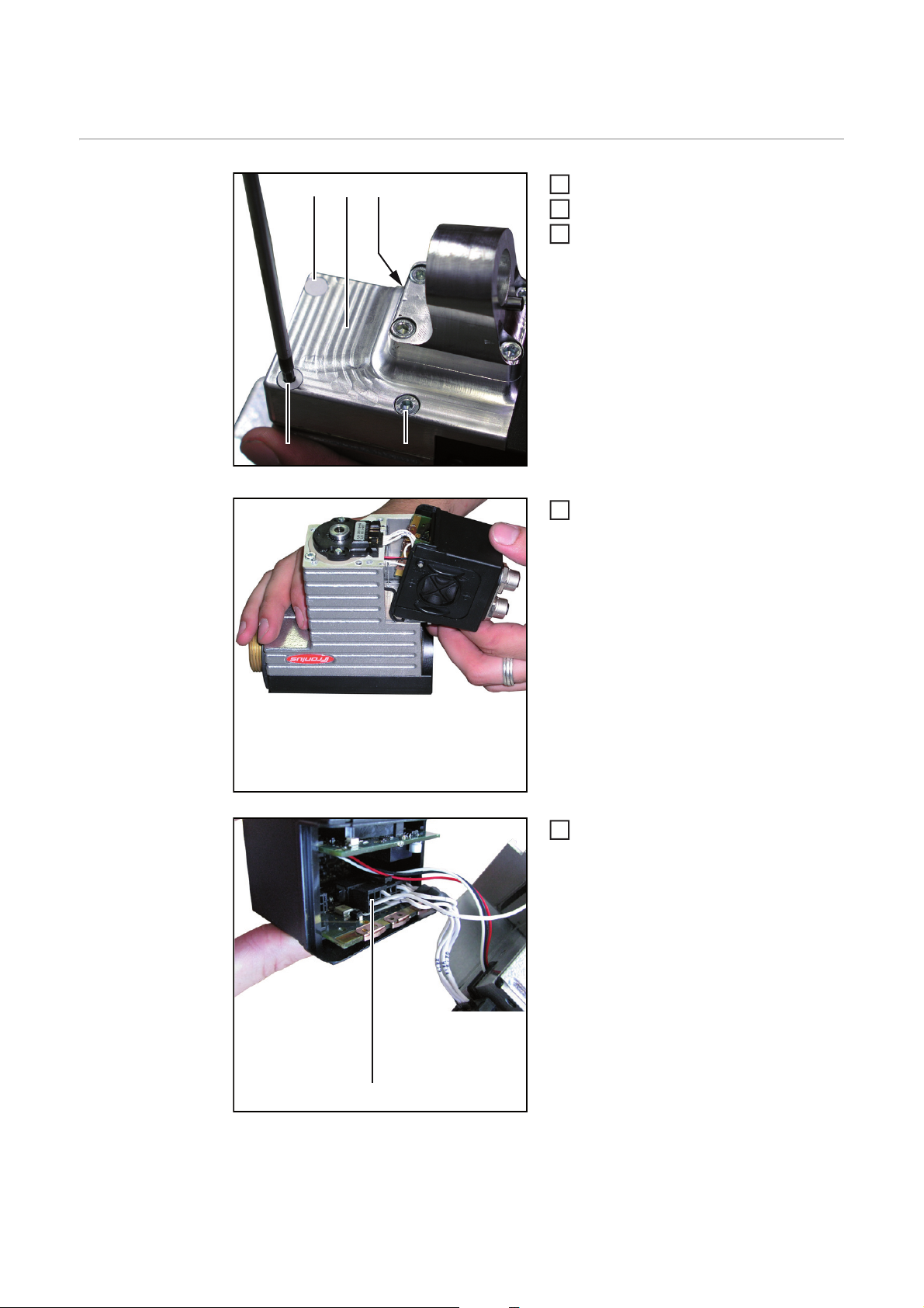
Replacing the encoder
(1+2) (2)
5
Preparing the
drive unit
(1+2)
(3)
(2)
Pierce the two seals (1)
1
Undo the four screws (2)
2
Take off the base plate (3) using a light
3
jerking movement
IMPORTANT! If a gasket is fitted, this must
remain on the motor housing.
Pull the electronics box backwards out
4
of the slot
30
Pull the plug (4) out of the RDIO 30 A
PC board
(4)
Page 33

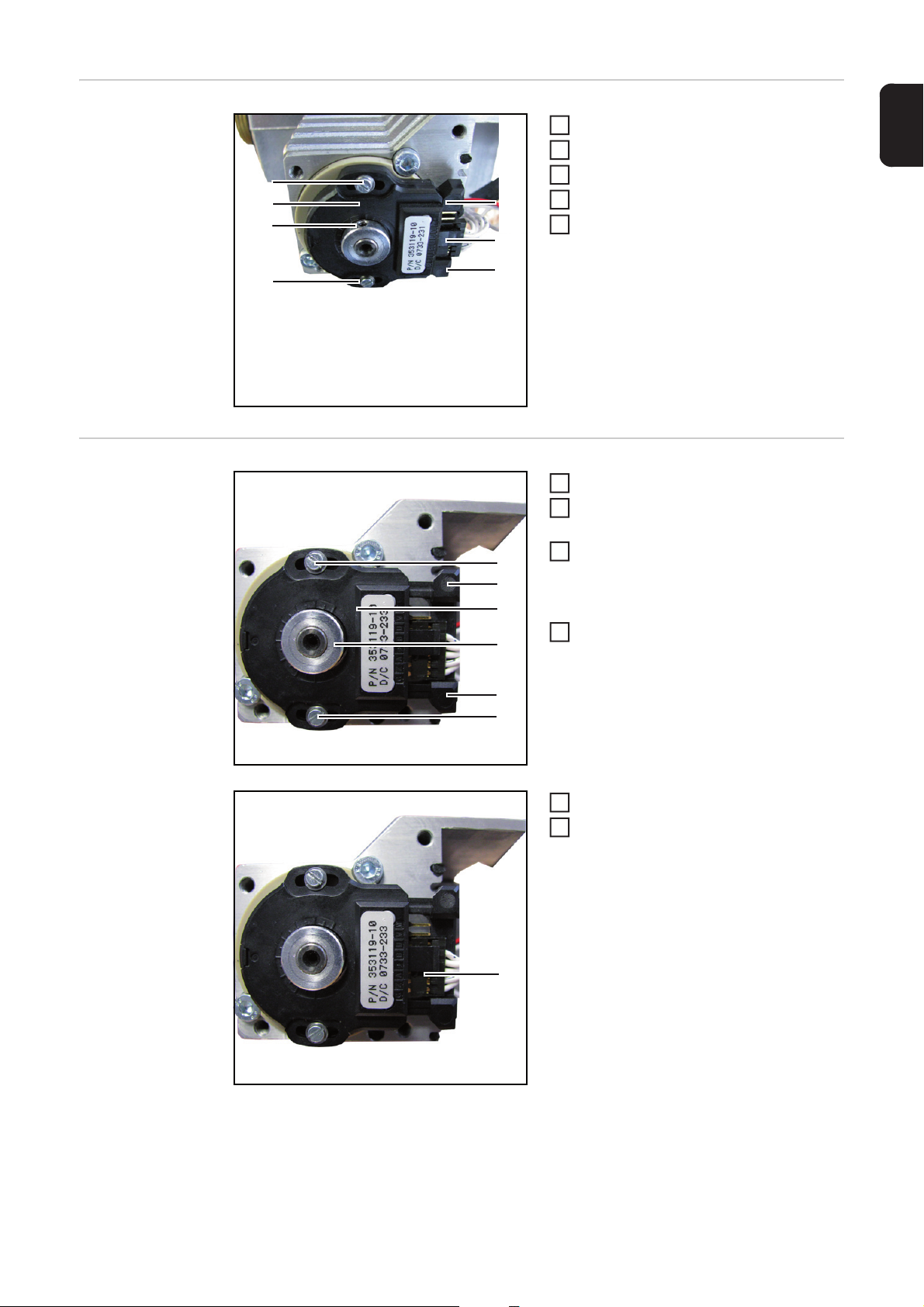
Removing the en-
(1)
(4)
(3)
(4)
(5)
(2)
(2)
2
4
(2)
(4)
(4)
(3)
(1)
(1)
3
5
coder
Pull the plug (1) out of the encoder
1
Pull out the encoder clip (2)
Undo the Allen screw (3)
3
Undo screws (4)
Pull off the encoder (5)
5
EN
Fitting the encoder
Pull out the encoder clip (1)
1
Place the encoder (2) on the drive unit
2
as shown
Push the encoder disc (3) towards the
drive unit
- This centres the encoder
Tighten the screws (4), tightening tor-
4
que = 0.2 Nm
Connect the plug (5) as shown
Set the encoder (see "Setting the en-
6
coder")
(5)
31
Page 34

Setting the encoder
3
6
(3)
(3)
(2)(1)
2
4
Connecting the
testbox to the
drive unit
Connect and secure the ENCODER
1
adapter to the testbox ENCODER connection
Connect the ENCODER adapter to the
2
drive unit
Connect and secure the MOTOR adapter to the testbox MOTOR connection
Connect the MOTOR adapter to the
4
electronics box as shown
Connect the testbox to the mains
5
Switch the testbox mains switch ON
Setting the encoder
32
Press the encoder disc (2) onto the drive unit and use the Allen key to turn the disc
7
until the testbox display shows 0 (tolerance = +/- 15)
Use the Allen screw to fix the encoder disc in this position, tightening torque = 0.4 Nm
8
Unscrew the Allen screw (1) in the en-
1
coder disc (2)
Apply Loctite 243 to the Allen screw
Screw Allen key back into the encoder
3
disc, but do not tighten
Turn the encoder disc (2) using the Al-
len key until the testbox display shows
a value greater than 0
Turn back the encoder disc (2) using
5
the Allen key until the testbox display
shows 0
Press the START key on the testbox
6
- The drive unit motor is supplied
with power for two minutes
Page 35

Press the STOP key on the testbox
9
- The power supply to the drive unit motor is stopped
Push the encoder clip (3) into the encoder
10
Check the encoder (see "Checking the encoder")
11
11
EN
33
Page 36

Checking the encoder
Checking the encoder settings
Checking the encoder for index
contact bounce
(1)
(1)
Turn the rotor shaft (1) until the testbox
1
display shows 350 (tolerance = +/-
150)
Press the START key on the testbox
2
- The drive unit motor is supplied
with power for two minutes
Check the value on the display
3
- The encoder is set correctly if a
value of between -15 and +15 is
displayed
- Adjust the encoder if a value outside the specified range is displayed
Press the STOP key on the testbox
4
- The power supply to the drive unit
motor is stopped
Check the encoder for index contact
5
bounce
Press UP on the testbox until LED L2
1
flashes
Press the Enter key on the testbox
2
- The testbox display shows 0
Turn the rotor shaft (1) until the testbox
3
display shows 1
Turn the rotor shaft (1) through another
4
360° until the testbox display shows 2
- The index may only be counted
once per complete rotation of the
rotor shaft
- If the index counts several times
during a complete rotation of the
rotor shaft, this indicates an installation error. Fix the problem
- If LED K4 lights up during a rotation of the rotor shaft, this indicates
an installation error. Fix the problem
Switch off the testbox
5
Unplug the testbox from the mains
6
34
Page 37

Finally...
4
Reassemble the
drive unit
(1)
Connect the plug (1) to the RDIO 30 A
1
PC board
Disconnect the ENCODER adapter
2
from the drive unit
Disconnect the MOTOR adapter from
3
the electronics box
IMPORTANT! Ensure that the foam rubber
seal is in the slot for the electronics box.
Place the electronics box on the drive
unit
EN
(2)
(2)
(2)
(2)
Locate the base plate
5
Fasten the base plate to the drive unit
6
with four screws (2)
- Tighten the screws diagonally
- Tightening torque = 3 Nm
35
Page 38

(3) (3)
Only when assembled in the factory:
7
seal the front two screws on the base
plate with the sealing labels (3)
36
Page 39

Care, maintenance and disposal
Safety
WARNING! Work that is carried out incorrectly can cause serious injury and dam-
age. All activities described in the operating instructions may only be carried out
by trained and qualified personnel. Personnel carrying out these activities must
have received training from Fronius in the correct operation of the device. Do not
carry out the work described until you have fully read and understood the following documents:
- these operating instructions
- all the operating instructions for the system components, especially the safety rules
WARNING! An electric shock can be fatal. Before opening the device:
- Switch the device mains switch to the "O" position
- Disconnect the device from the mains
- Ensure that the device remains disconnected from the mains until all work
has been completed
After opening the device, use a suitable measuring instrument to check that electrically charged components (e.g. capacitors) have been discharged.
WARNING! Inadequate PE conductor connections can cause serious injury and
damage. The housing screws provide a suitable PE conductor connection for
earthing (grounding) the housing and must NOT be replaced by any other screws
which do not provide a reliable PE conductor connection.
EN
At every start-up - Check the mains plug and mains cable for damage
- Check the adapter cable for damage
Every 6 months
- Remove the cover from the device and clean the inside with dry reduced compressed
Disposal Dispose of in accordance with the applicable national and local regulations.
NOTE! Risk of damage to electronic components. Do not bring the air nozzle too
close to electronic components.
air
37
Page 40

Inspection documentation
Inspection documentation
Inspected device
Device inspected by
Inspection carried out on
Faults found
Measures taken to rectify
fault
Fault rectified on
Inspected device
Device inspected by
Inspection carried out on
Faults found
Measures taken to rectify
fault
Fault rectified on
Inspected device
Device inspected by
Inspection carried out on
Faults found
Measures taken to rectify
fault
Fault rectified on
38
Page 41

Technical data
CMT encoder
testbox
Mains voltage 1 (U
Mains frequency 50 / 60 Hz
Nominal current 0.8 A
Degree of protection IP 20
Marks of conformity CE
) 100 V - 240 V
1
EN
39
Page 42

FRONIUS INTERNATIONAL GMBH
Froniusplatz 1, A-4600 Wels, Austria
Tel: +43 (0)7242 241-0, Fax: +43 (0)7242 241-3940
Under http://www.fronius.com/addresses you will find all addresses
of our Sales & service partners and Locations
E-Mail: sales@fronius.com
www.fronius.com
www.fronius.com/addresses
 Loading...