

Page 1

APPLICATION GUIDE
SETTING UP FULL BATTERY BACKUP
WITH FRONIUS SYMO GEN24 PLUS (6 - 10)
THIS DOCUMENT AIMS TO PROVIDE EASY-TO-FOLLOW INSTRUCTIONS ON HOW TO BEST DEPLOY
THE BATTERY BACKUP FUNCTION OF FRONIUS SYMO GEN24 PLUS (6 - 10) INVERTER SYSTEM
Application Guide
© Fronius Australia Pty Ltd.
Version 3.0/2021
Fronius reserves all rights, in particular rights of reproduction, distribution and translation.
No part of this work may be reproduced in any way without the written consent of Fronius. It must not be saved, edited,
reproduced or distributed using any electrical or electronic system.
You are hereby reminded that the information published in this document, despite exercising the greatest of care in its
preparation, is subject to change and that neither the author nor Fronius can accept any legal liability
Gender-specific wording refers equally to female and male form.
(c) Fronius Australia Pty. Ltd, 2021 1/16
Page 2

Date
Version
Comments
Author
08/09/21
3.0
Multiple major changes
Fronius Australia
06/11/20
1.1
Figure 1 updated and other minor changes
Fronius Australia
28/10/20
1.0
Initial release
Fronius Australia
1. CHANGE LOG
2. GENERAL
Fronius Symo GEN24 Plus (6 - 10) offers the opportunity to supply select electrical loads (1 and/or 3-phase) or
possibly entire household during grid outages. This functionality is referred to as Full Backup function.
This solution works in combination with an energy storage system and supplies electrical loads whenever
sufficient energy is available.
Key features are:
Supply electrical loads in grid outage (1 and/or 3-phase loads),
Automatic switch to backup power in the event of grid failure,
Efficient energy flows due to the Multi-Flow Technology, even in backup power situation.
o This means even in backup mode PV is operational and could charge the battery.
3. REQUIREMENTS
Basic requirements for using the full backup functionality are correctly installed and configured:
Fronius Smart Meter,
Compatible BYD battery,
External backup control and switchover components.
Having PV installed is optional, but recommended because it could charge the battery in backup mode during
sun hours (if sufficient power is available) which makes this solution self-sustainable.
For successful integration please make sure the following items are ticked:
Inverter is Fronius Symo GEN24 6.0/8.0/10.0 Plus,
Suitable battery is installed,
Inverter+Battery capacity is suitable for the backup loads,
Fronius Smart Meter is correctly installed (feed-in point),
Correct Hardware is applied,
Correct Software Settings is applied,
Warning notice - Backup Power Supply is installed, see appendix A,
Backup power checklist is completed, see appendix B.
(c) Fronius Australia Pty. Ltd, 2021 2/16
Page 3

4. TECHNICAL INFORMATION
4.1 Battery compatibility
Compatible batteries are listed below.
Table 4.1.a: Symo GEN24 Plus compatible BYD batteries
4.2 BYD Battery-Box Premium information
Key relevant specifications of the BYD Battery-Box Premium batteries are shown below. For more information
please visit BYD’s online documentation available here.
Table 4.2.a: BYD Battery-Box HVS/HVM Premium specifications
Table 4.2.b: Charging/discharging capability of Fronius Symo GEN24 Plus and BYD HVM/HVS
It is possible to combine multiple BYD batteries to increase energy storage capacity, with key information show
below. Compatibility confirmation it is available here.
Table 4.2.c: Compatibility with paralleled BYD HVM/HVS batteries.
* Follow BYD's installation manual on correct installation/configuration instructions when paralleling multiple batteries.
(c) Fronius Australia Pty. Ltd, 2021 3/16
Page 4
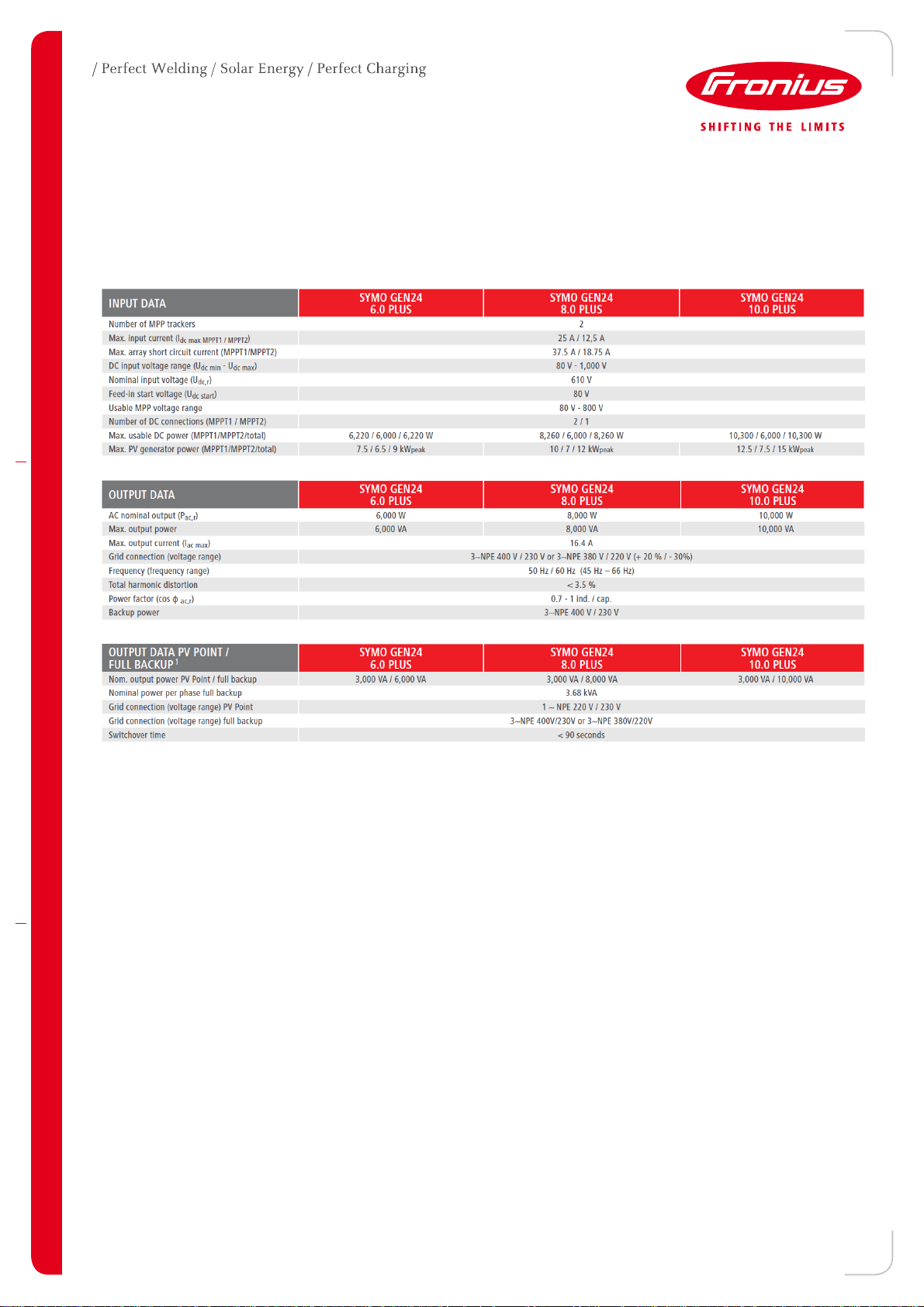
4.3 Symo GEN24 Plus information
Fronius Symo GEN24 Plus inverter is available in a few different power classes ranging from 3.0 to 10.0 kVA.
However, full backup functionality (due to capacity constraints) is only available for power classes of 6 kVA, 8
kVA, and 10 kVA. Inverter's technical details are shown below.
Table 4.3.a: Symo GEN24 6.0/8.0/10.0 Plus technical details
(c) Fronius Australia Pty. Ltd, 2021 4/16
Page 5

Power Class
6.0
8.0
10.0
Total Power Continuous [VA]
6000
8000
10000
Overload (5 sec) [VA]
12400
12400
12400
Power Per Phase
Continuous [VA]
3680
3680
3680
Overload (5 sec) [VA]
4133
4133
4133
Phase loads
L1 loads
L2 loads
L3 loads
Total loads
Comment
Example 1
1 kW / 1 kVA
3 kW / 3 kVA
2 kW / 2 kVA
6 kW / 6 kVA
Battery capacity surpassed
Example 2
4 kW / 4 kVA
0 / 0
0 / 0
4 kW / 4 kVA
Inverter overload (L1)
Example 3
2 kW / 2 kVA
2 kW / 2.5 kVA
0 kW /0 kVA
4 kW / 4.5 kVA
Ok
Phase loads
L1 loads
L2 loads
L3 loads
Total loads
Comment
Example 1
1 kW / 1 kVA
3.5 kW / 3.5 kVA
2 kW / 2 kVA
6.5 kW / 6.5 kVA
Ok
Example 2
0 / 0
5 kW / 5 kVA
0 / 0
5 kW / 5 kVA
Inverter overload (L2)
Example 3
3 kW / 3.5 kVA
2 kW / 3 kVA
3 kW / 3.5 kVA
8.5 kW / 10 kVA
Ok
1
4.4 Backup Capability - Nominal and Overload
Continuous and overload capability1 of the inverters are listed below.
Table 4.4.a: AC output capability for Symo GEN24 Plus
Any active power demand imposed to the inverter from the loads will be met with energy coming from the
battery and PV, if available.
Any reactive power demand imposed to the inverter from the loads will be met without discharging the battery or
without using energy from PV, if available.
4.4.1 System Capacity Limitations - Examples
To better explain the continuous capacity constraints of the whole system comprised of batteries and inverter,
two examples with different load configurations are shown below.
Example 1: Symo GEN24 8.0 Plus + BYD HVM 11
Max battery discharge 4.5 kW,
Max inverter capacity (total): 8 kVA,
Max inverter capacity (per phase): 3.68 kVA.
Table 4.4.1.a: Example 1 System and loads capacity considerations
Example 2: Symo GEN24 10 Plus + BYD HVS 10.2
Max battery discharge: 9 kW,
Max inverter capacity (total) 10 kVA,
Max inverter capacity (per phase): 3.68 kVA.
Table 4.4.1.b: Example 1 System and loads capacity considerations
The key takeaway is to understand the capacity limitations of the whole system comprised of a battery and an
inverter.
As PV might be present during the backup operation, it will top up the battery capacity if available and if
needed. However, as PV by nature is not a reliable energy source this can’t be guaranteed.
Note 1: Battery size/capacity may limit this further, refer to table 4.2.b
(c) Fronius Australia Pty. Ltd, 2021 5/16
Page 6

5. OPERATIONAL MODES
There are two main operational modes, Grid and Backup as well as one informational Energy Saving mode,
discussed in detail below.
5.1 GRID MODE
This mode denotes that the inverter is AC coupled with the local grid, backup control logic is turned off and
backup loads supplied from the grid.
5.1.1 GRID-TO-BACKUP TRANSITION
Successful transition to backup mode requires the following conditions to be met:
1) Grid (via the AC port of the inverter) is monitored by the inverter’s internal protection unit and Fronius
Smart Meter.
2) Grid fails (blackout).
3) The inverter carries out measurement according to country standard and then shuts down.
4) The inverter starts Backup mode after a short time window.
5) Backup control logic is switched on and loads connected to the backup power circuit are supplied by
the inverter.
5.2 BACKUP MODE
Operation in Backup mode usually means the grid is not available and the inverter is supplying backup loads.
The interlocking mechanism from the backup control components is on/activated.
In backup mode inverter's AC output acts as a voltage source with AC voltage set at 230/400 Vac (L-N/L-L) and
AC frequency set at 53 Hz. AC frequency is purposely increased with the intention of disconnecting other
inverters connected to the backup circuit if any.
5.2.1 BACKUP-TO-GRID TRANSITION
Successful transition to grid mode requires the following conditions to be met:
1) Inverter operating in backup power mode.
2) The grid is back and stable.
3) Fronius Smart Meter monitors grid voltage values and passes this information to the inverter.
4) Inverter checks if the grid voltage is within the correct range.
5) Inverter ends backup power mode.
6) Backup control logic is turned off and AC loads are reconnected to the grid.
7) The inverter checks if the grid is within specified parameters (relevant standard) and if successful starts
producing energy.
5.3 ENERGY SAVING MODE
Energy Saving mode usually means that the battery is running at or below the minimum state of charge and
there is no sufficient power to charge (PV or grid).
The inverter enters this mode if either of the following is true:
1) The battery is discharged to the minimum state of charge and no energy is coming from the PV
modules.
2) The inverter/battery is set to Energy Saving mode (standby mode).
If battery and inverter are in Energy Saving mode, the system could be reactivated by one of the following:
1) Enough energy is available from the solar PV modules.
2) Grid is functioning again.
3) The battery is switched off and on.
(c) Fronius Australia Pty. Ltd, 2021 6/16
Page 7

Option 1 2
3
4
Manufacturer
ABB
Finder
IMO
IMO
Type
EBS-63-31
22.64.0.230.4710
HC63-31230
HC63-40230
HCA11
Component
Description
Main
Main
Main
Main
Auxiliary
Control Coil
Rated Voltage
230 Vac @ 50 Hz
230 Vac @ 50 Hz
230 Vac @ 50 Hz
230 Vac @ 50 Hz
Mechanical
interlock
Control Coil
Power Consumption
5.10 VA
5 VA
6 – 8 VA
6 – 8 VA
N/A
Pole Configuration
3 NO + 1 NC
3 NO + 1 NC
3 NO + 1 NC
4 NO
1 NO + 1 NC
Rated Voltage
230/400 Vac @ 50
Hz
230/400 Vac @ 50
Hz
230/400 Vac @ 50
Hz
230/400 Vac @ 50
Hz
As main module
Rated Current
63 A
63 A
63 A
63 A
3 A
Image
N/A N/A
Option
1
Manufacturer
Finder
Type
22.23.9.012.4000
Control Coil Rated
Voltage
12 Vdc
Control Coil
Power Consumption
1.25 VA
Pole configuration
1 NO + 1 NC
Rated Voltage
230 Vac @ 50 Hz
Rated Output
20 A
Image
6. HARDWARE SETUP
6.1 Required Components – Backup Control
For successful battery backup interfacing, external components K1 (main) and K3 (interface) are required, and
not supplied with the unit. They will need to be purchased separately from your electrical wholesaler or electrical
supplier.
Compatible options for K1 are shown below. Option four requires two devices main and auxiliary component,
while options one through three require main component only.
Table 6.1.a: Options for K1 – Main
Compatible devices for K3 are shown in the table below. Unfortunately, only one option is available at the
moment. If you have an alternative that matches the requirements feel free to contact us directly at the email
supplied at the end of the document.
Table 6.1.b: Options for K3 – Interface
(c) Fronius Australia Pty. Ltd, 2021 7/16
Page 8
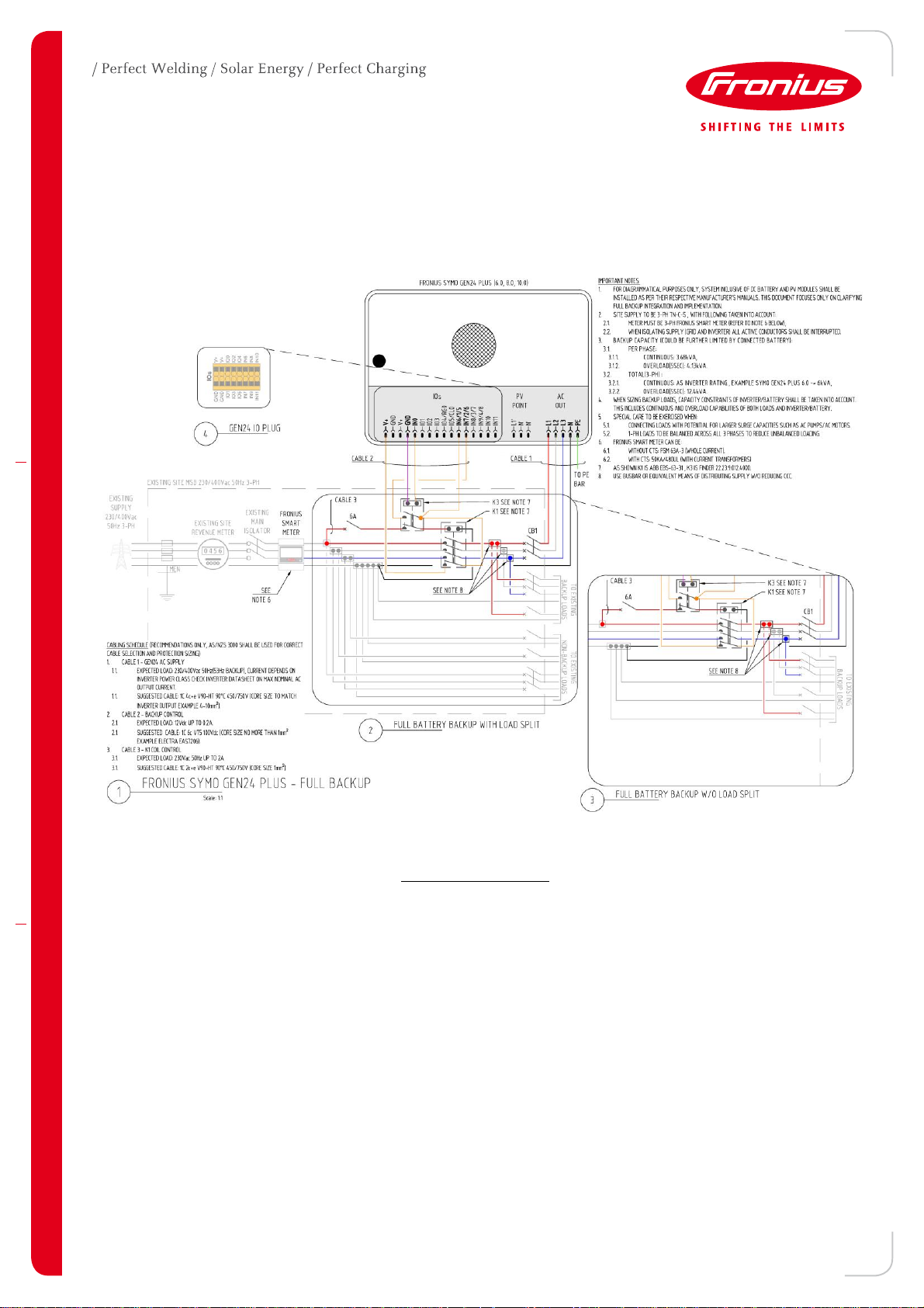
6.2 Control Wiring
The figure below shows a typical wiring diagram of the backup control interface with necessary backup control
components. Also shown in Appendix D for better clarity.
Figure 6.2.a: Backup control wiring diagram (K1 matching option 1)
Important notes to consider:
1) Components K1 and K3 need to be purchased separately from relevant electrical suppliers.
2) When selecting/installing K1 ensure connected load capacity is lower than the capacity of the contactor.
Special considerations must be in place for sites that have only backup loads and/or other inverter in
backup circuit.
(c) Fronius Australia Pty. Ltd, 2021 8/16
Page 9

6.2.1 Control Wiring - Correct Device Positioning
When following the Control Wiring it’s important to understand correct device positioning is crucial to ensure
correct operation of the full backup functionality.
Important points relevant to correct device positioning are as follows:
1) Fronius Smart Meter installed at the feed-in point.
2) K1 main contacts:
a. 3x NO installed at:
i. Load side of Fronius Smart Meter and,
ii. Supply side of Backup loads/GEN24 Inverter.
b. 1x NC installed at:
i. Supply side of K3 NC coil and,
ii. Load site of V+ terminals.
3) K1 control coil installed at load side Fronius Smart Meter (L1/Red phase) and supply side of K1 main
contacts.
4) Backup loads & GEN24 inverter installed at load side of K1 main contacts (3xNO).
5) Non-backup loads (if present) installed at load side of Fronius Smart Meter and supply side of K1.
Additional PV inverters – Grid only (AS/NZS 4777 compliant) can be installed in the backup power circuit. As
operational frequency in backup mode is 53 Hz they will not produce power.
6.2.2 GEN24 Pilot – Connection Area
Figure 6.2.2.a: Backup control wiring connection area (GEN24 Pilot)
Figure 6.2.2.b: GEN24 Pilot connection area
(c) Fronius Australia Pty. Ltd, 2021 9/16
Page 10
7. SOFTWARE SETUP
The following assumes standard commissioning process for the Battery and Inverter (including Fronius Smart
Meter) have been completed.
GEN24 installation instructions GEN24 Operation manual,
GEN24 commissioning Fronius Solar.Start from your phone/tablet/pc.
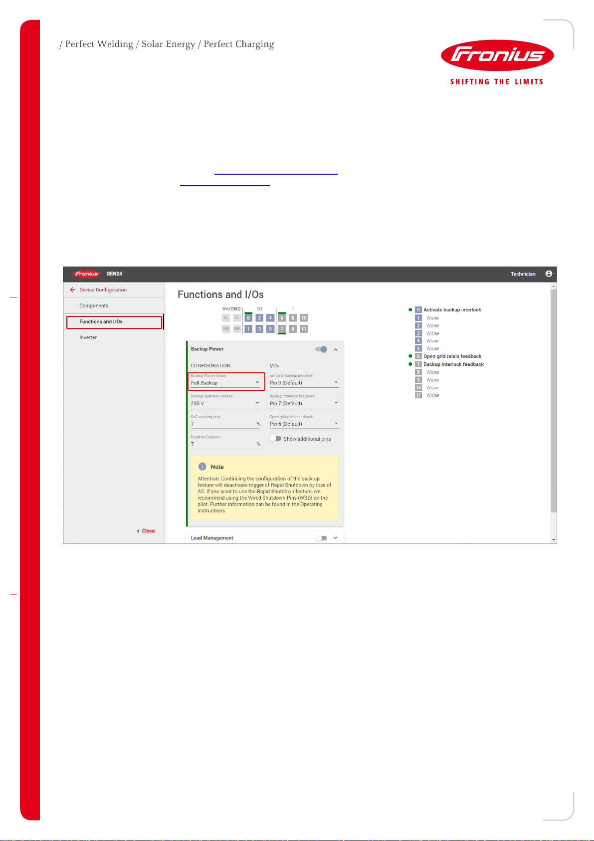
When ready to set the full backup mode, follow the steps below:
1) From the WebUI, log in as Technician
2) Go to Device Configuration Functions and I/Os
3) Select Backup Power and set Backup Power Mode to Full Backup, refer to below.
Figure 7.a: Battery backup setup – functions and I/Os
(c) Fronius Australia Pty. Ltd, 2021 10/16
Page 11

Mode
Grid
IO0
DI6
DI7
K3
K1
Backup
loads
Non-
backup
loads
Grid
ON
OFF
OFF
OFF
DISENGAGED
ENGAGED
ON
ON
Backup
OFF
ON
ON
ON
ENGAGED
DISENGAGED
ON
OFF
Function
Contact
Purpose & clarification
Activate feedback
K3 COIL/IO0
When the inverter wants to turn on Backup Mode IO0 is energized
(12Vdc), which in turn engages K3 -> disengages K1
Grid Isolation
K3 NC
Supplies 230Vac to K1 coil which in turn connect or disconnect backup
loads and inverter to the grid
Backup interlock
feedback
K3 NO
Signals the state of the backup mechanism
Open grid relay
feedback
K1 NC
Signals the state of the grid to the inverter
8. TESTING & TROUBLESHOOTING
8.1 Testing
Test backup mode functionality when the system is installed and commissioned for the first time. The battery
should have a state of charge of at least 30% when performing the test.
Furthermore, we have developed a checklist that clearly shows steps to be followed for successful integration,
shown in Appendix B (click on the image for the actual document).
Upon successful commissioning, Fronius Battery Warning Notice, shown in Appendix A, could be used to
denote Backup presence at premises.
8.2 Troubleshooting
The table below summarises states of important control parameters which could be used for troubleshooting or
assessing faulty components. For example, when Grid mode is active K1 is Engaged, IO0 is OFF, etc.
Table 8.2.a: Input/output states as a function of main operational modes
Additional clarification of the control logic and used contacts with their accompanying actions is shown below.
Table 8.2.b: Backup control functions and relevant contacts
(c) Fronius Australia Pty. Ltd, 2021 11/16
Page 12

9. APPENDIX A – WARNING NOTICE BACKUP POWER
(c) Fronius Australia Pty. Ltd, 2021 12/16
Page 13

10. APPENDIX B – BACKUP INSTALLATION CHECKLIST
(c) Fronius Australia Pty. Ltd, 2021 13/16
Page 14

K1 – main
K3 – interface
Main Contacts
Main pole configuration
1 NO + 1 NC
1 NO + 1 NC
Rated Operational Voltage
230 Vac
230 Vac / 12 Vdc
Rated Operational Current
at least 63 A
at least 10 A
Rated Operational Frequency
50 Hz
50 Hz / DC
Control Coil
Rated Operational Voltage
230 Vac
12 Vdc
Rated Operational Frequency
50 Hz
n/a (DC)
Rated Inrush Power
below 100 VA
below 3 W
11. APPENDIX C – BACKUP CONTROL K1 AND K3 REQUIREMENTS
Table C.1: Backup control components – operational requirements
(c) Fronius Australia Pty. Ltd, 2021 14/16
Page 15

12. APPENDIX D – CONTROL WIRING
(c) Fronius Australia Pty. Ltd, 2021 15/16
Page 16

END OF DOCUMENT
Fronius Australia Technical Support
Email: PV-Support-Australia@fronius.com
Phone: 03 8340 2910
For more detailed information see the operation manual available on the product specific page on http://www.fronius.com/en-au/australia
(c) Fronius Australia Pty. Ltd, 2021 16/16
 Loading...