

Fronius Smart Meter 240V-3 UL, Smart Meter 600V-3 UL, Smart Meter 480V-3 UL Operating Instructions Manual [es, en]
Page 1
/ Perfect Charging / Perfect Welding / Solar Energy
Fronius Smart Meter 240V-3 UL
Fronius Smart Meter 480V-3 UL
Fronius Smart Meter 600V-3 UL
Operating Instructions
System monitoring
EN-USES
Manual de instrucciones
Supervisión del equipo
42,0410,2289 004-10052017
Page 2

2
Page 3
Dear reader,
Introduction Thank you for the trust you have placed in our company and congratulations on buying this
high-quality Fronius product. These instructions will help you familiarize yourself with the
product. Reading the instructions carefully will enable you to learn about the many different
features your Fronius product has to offer. This will allow you to make full use of its advantages.
Please also note the safety rules to ensure greater safety when using the product. Careful
handling of the product will repay you with years of safe and reliable operation. These are
essential prerequisites for excellent results.
EN-US
Explanation of
Safety Instructions
DANGER! Indicates an immediate danger. Death or serious injury may result if
appropriate precautions are not taken.
WARNING! Indicates a possibly dangerous situation. Death or serious injury may
result if appropriate precautions are not taken.
CAUTION! Indicates a situation where damage or injury could occur. Minor injury
or damage to property may result if appropriate precautions are not taken.
NOTE! Indicates the possibility of flawed results and damage to the equipment.
IMPORTANT! Indicates tips for correct operation and other particularly useful information.
It does not indicate a potentially damaging or dangerous situation.
If you see any of the symbols depicted in the "Safety Rules," special care is required.
3
Page 4

4
Page 5

Contents
Safety rules ................................................................................................................................................ 7
General ................................................................................................................................................. 7
Environmental Conditions..................................................................................................................... 7
Qualified Service Engineers.................................................................................................................. 8
Copyright............................................................................................................................................... 8
Backup.................................................................................................................................................. 8
FCC / RSS Compliance ........................................................................................................................ 9
Warning notices on the device.............................................................................................................. 9
Installation.................................................................................................................................................. 10
Installation Checklist ............................................................................................................................. 10
Mounting ............................................................................................................................................... 10
Circuit Protection................................................................................................................................... 11
Line Wiring............................................................................................................................................ 11
Connect Current Transformers ............................................................................................................. 14
CT Wiring.............................................................................................................................................. 14
Connecting the Data Communication Signals ......................................................................................15
Terminating Resistors........................................................................................................................... 15
Modbus RTU......................................................................................................................................... 16
Set Terminating Resistor ...................................................................................................................... 16
Set Baud Rate....................................................................................................................................... 17
Configuration Web Interface ................................................................................................................. 17
Operation ................................................................................................................................................... 18
Power Status LEDs............................................................................................................................... 18
Modbus Communication LEDs ............................................................................................................. 19
Technical Data ........................................................................................................................................... 20
Accuracy ............................................................................................................................................... 20
Measurement........................................................................................................................................ 20
Models and Electrical............................................................................................................................ 20
Certifications ......................................................................................................................................... 21
Environmental....................................................................................................................................... 21
Mechanical............................................................................................................................................ 21
Fronius Manufacturer's Warranty.......................................................................................................... 21
EN-US
5
Page 6

6
Page 7
Safety rules
EN-US
General
The device has been manufactured using state-of-the-art technology and according to recognized safety standards. If used incorrectly or misused, however, it can cause
- injury or death to the operator or a third party
- damage to the device and other material assets belonging to the operating company
- inefficient operation of the equipment
All persons involved in start-up operation, maintenance and servicing for the
device must
- be suitably qualified
- have knowledge of and experience in dealing with electrical installations
and
- have completely read and followed these operating instructions
The operating instructions must always be at hand wherever the device is being used. In addition to the operating instructions, all applicable local rules and
regulations regarding accident prevention and environmental protection must
also be followed.
All safety and danger notices on the device
- must be kept in a legible state
- must not be damaged/marked
- must not be removed
- must not be covered, pasted or painted over
The terminals can reach high temperatures.
Only operate the device when all protection devices are fully functional. If the
protection devices are not fully functional, there is a risk of
- injury or death to the operator or a third party
- damage to the device and other material assets belonging to the operating company
- inefficient operation of the device
Safety devices that are not fully functional must be repaired by an authorized
specialist before the device is turned on.
Never bypass or disable protection devices.
For the location of the safety and danger notices on the device, refer to the
section headed "General" in the operating instructions for the device.
Any equipment malfunctions which might impair safety must be remedied im-
mediately before the device is turned on.
Your personal safety is at stake!
Environmental
Conditions
Operation or storage of the device outside the stipulated area will be deemed
as "not in accordance with the intended purpose." The manufacturer is not responsible for any damages resulting from unintended use.
For exact information on permitted environmental conditions, please refer to
the "Technical data" in the operating instructions.
7
Page 8

Qualified Service
Engineers
The servicing information contained in these operating instructions is intended
only for the use of qualified service engineers. An electric shock can be fatal.
Do not carry out any actions other than those described in the documentation.
This also applies to qualified personnel.
All cables and leads must be secured, undamaged, insulated, and adequately
dimensioned. Loose connections, scorched, damaged, or under-dimensioned
cables and leads must be repaired immediately by an authorized specialist.
Maintenance and repair work must only be carried out by authorized personnel.
It is impossible to guarantee that externally procured parts are designed and
manufactured to meet the demands made on them, or that they satisfy safety
requirements. Use only original spare parts (also applies to standard parts).
Do not carry out any alterations, installations, or modifications to the device
without first obtaining the manufacturer’s permission.
Components that are not in perfect condition must be changed immediately.
Copyright
Backup
Copyright of these operating instructions remains with the manufacturer.
Text and illustrations are technically correct at the time of going to print. The
right to make modifications is reserved. The contents of the operating instructions shall not provide the basis for any claims whatsoever on the part of the
purchaser. If you have any suggestions for improvement, or can point out any
mistakes that you have found in the operating instructions, we will be most
grateful for your comments.
The user is responsible for backing up any changes made to the factory settings. The manufacturer accepts no liability for any deleted personal settings.
8
Page 9
FCC / RSS Compliance
FCC
EN-US
This device corresponds to the limit values for a digital device of class B in
accordance with Part 15 of the FCC regulations. The limit values should provide adequate protection against harmful interference in homes. This device
creates and uses high frequency energy and can interfere with radio communications when not used in accordance with the instructions. However,
there is no guarantee against interference occurring in a particular installation.
If this device interferes with radio or television reception when turning the device on and off, it is recommended that the user solve this with one or more
of the following measures:
- adjust or reposition the receiving antenna
- increase the distance between the device and the receiver
- connect the device to another circuit, which does not include the receiver
- for further support, please contact the retailer or an experienced radio/
TV technician.
Industry Canada RSS
The device corresponds to the license-free Industry Canada RSS standards. Operation is subject to the following conditions:
(1) The device may not cause harmful interference
(2) The device must accept any interference received, including interference that may cause undesired operation.
Warning notices
on the device
Safety symbols:
To avoid electric shocks:
- Do not dismantle or modify the device
- Do not allow any water to enter the device
- Do not allow any foreign substances or material to enter the device
- Do not touch any connections directly
RCM Symbol - The product complies with the Australian laws.
9
Page 10
Installation
Installation
Checklist
See the sections referenced below for installation details
Turn off power before making line voltage connections
1
Mount the Fronius Smart Meter (see “Mounting“)
2
Connect circuit breakers or fuses and disconnects (see “Circuit Protection“)
3
Connect the line voltage wires to the meter‘s terminal block (see “Line Wiring“)
4
Mount the Current Transformers (CTs) around the line conductors. Make sure the CTs
5
face the correct direction. An arrow might indicate either the load or the source (public
grid) (see “Connect Current Transformers“)
Connect the twisted white and black wires form the CTs to the terminal block on the
6
meter, matching the wire colors to the white and black dots on the meter label (see
“CT Wiring“)
Check that the CT phases match the line voltage phases (see “Connect Current
7
Transformers“)
Record the CT rated current for each meter, because it will be required during setup
8
Connect the output terminals of the Fronius Smart Meter to the monitoring equipment
9
(see “Connecting the Data Communication Signals“)
If necessary set terminating resistors (see “Terminating Resistors“)
10
Check that all the wires and plugs are securely installed in the terminal blocks by tug-
11
ging on each wire
Turn on the power to the Smart Meter
12
Verify that the LEDs indicate correct operation. If there is a consumption of power and
13
all generated power sources are turned off, then the LEDs from the used phases
should flash green (see “Operation“).
Check your Fronius System monitoring software. In order to ensure compatibility be-
14
tween the inverter and the Smart Meter, software must always be kept up-to-date. The
update can be started via the inverter website.
Set CT-Ratio and Grid Type on the web interface of the Fronius Datamanager in Set-
15
tings - Meter - Settings (see “Configuration web interface“)
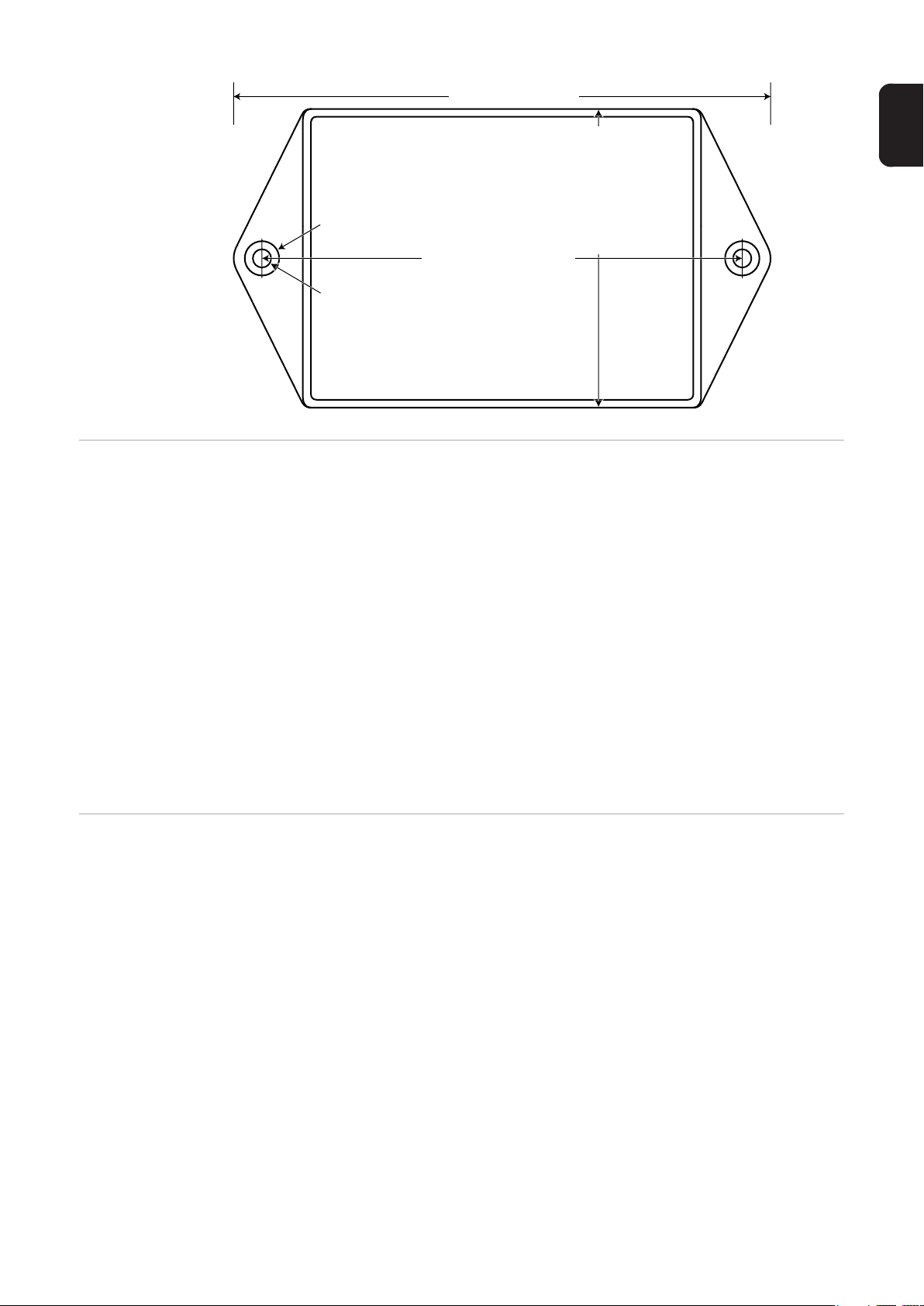
Mounting The Fronius Smart meter has two mounting holes spaced 5.375 in. (137 mm) apart (center-
to-center). These mounting holes are normally obscured by the detachable screw terminals. Remove the screw terminals to mark the hole positions and mount the meter.
Self-tapping sheet metal screws are included. Do not over-tighten the screws, as long-term
stress on the case can cause cracking.
10
Page 11
153 mm (6.02 in)
85.1 mm (3.35 in)
Ø
9.8 mm (0.386 in)
136.6 mm (5.375 in)
Ø
5.1 mm (0.200 in)
38 mm (1.50 in) High
Circuit Protection The Fronius Smart Meter is considered “permanently connected equipment“ and requires
a disconnect means (circuit breaker, switch or disconnect) and overcurrent protection (fuse
or circuit breaker).
EN-US
The Fronius Smart Meter only draws 10-30 mA, so the rating of any switches, disconnects,
fuses and / or circuit breakers is determined by the wire gauge, the mains voltage and the
current interrupting rating required.
- The switch, disconnect or circuit breaker must be within sight and as close as practicable to the Fronius Smart Meter and must be easy to operate.
- Use circuit breakers or fuses rated for 20 amps or less.
- Use ganged circuit breakers when monitoring more than one line voltage.
- The circuit breakers or fuses must protect the mains terminals labeled L1, L2 and L3.
In the rare cases where neutral has overcurrent protection, the overcurrent protection
device must interrupt both neutral and ungrounded conductors simultaneously.
- The circuit protection / disconnect system must meet IEC 60947-1 and IEC 60947-3,
as well as all national and local electrical codes.
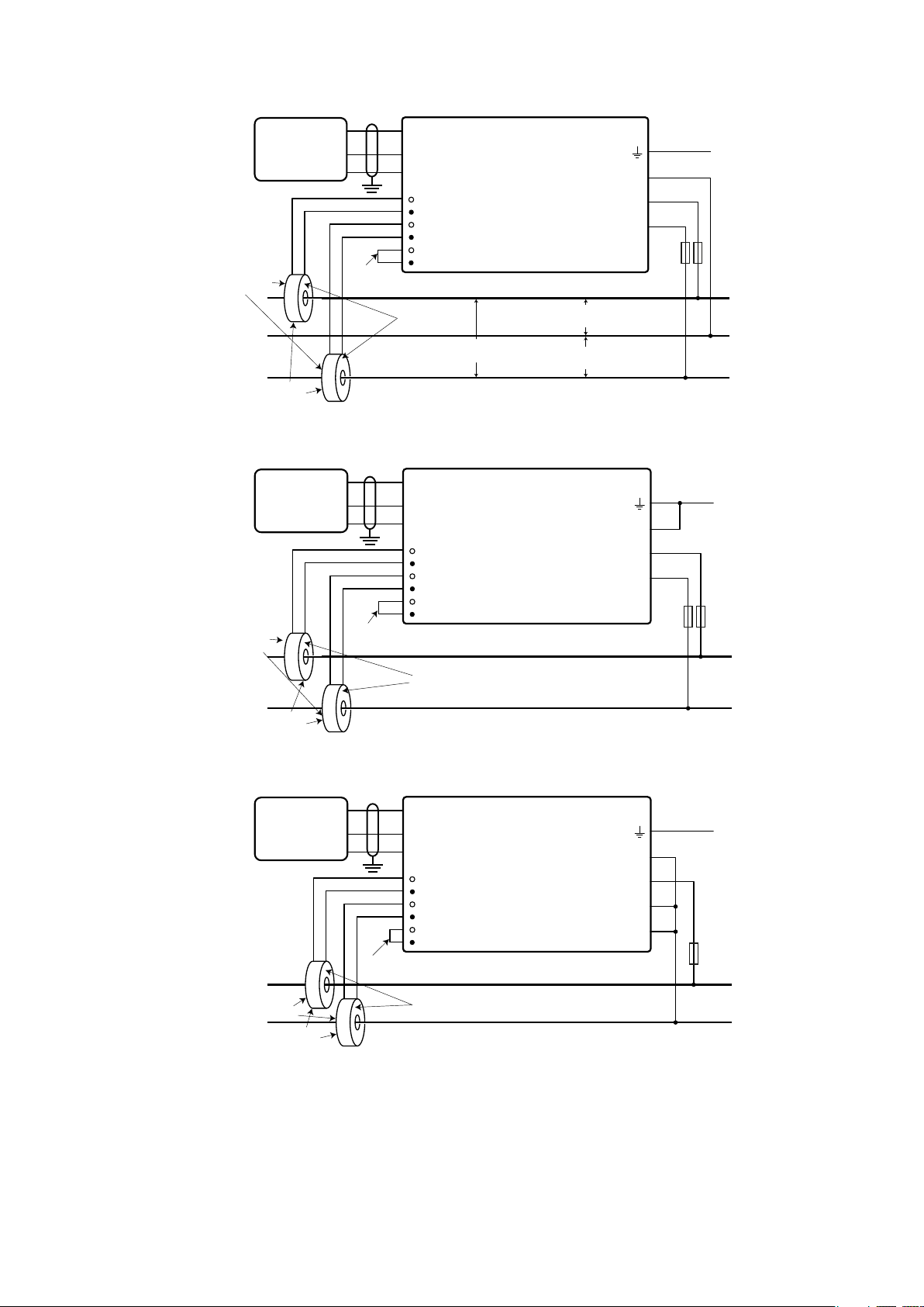
Line Wiring - Always turn off power before connecting the line voltage inputs to the Fronius Smart
Meter.
- For the line voltage wires, 16 to 12 AWG stranded wire, type THHN, MTW or THWN,
600 V are recommended.
- Do not place more than one wire per screw terminal; use separate wire nuts or terminal blocks if needed.
- Verify that the line voltages match the line-to-line and line-to-neutral values printed in
the white box on the front label.
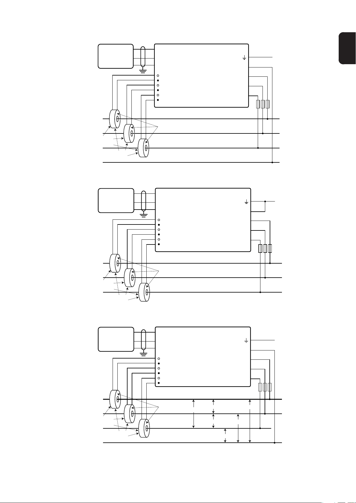
Connect each conductor to the appropriate phase; also connect ground and neutral (if applicable). The neutral connection “N“ is not required on delta models but we recommend
connecting it to ground if neutral is not present.
The screw terminal can handle wire up to 12 AWG. Connect each voltage line to the green
terminal block as shown in the following figures. After the voltage lines have been connected, make sure both terminal blocks are fully seated in the Fronius Smart Meter.
When power is first applied, check that the LEDs behave normally. If you see LEDs flashing
red-green-red-green, the voltage is too high for this model, so disconnect the power switch
immediately!
11
Page 12
Single-Phase Three-Wire (Mid-Point Neutral)
Fronius
Datama-
nager
WHITE
Load
Faces
LOAD
Current
Tran sformers
D-
D+
-
WHITE
BLACK
BLACK
Shorting
Jumper
D-
D+
-
CT L1
CT L2
CT L3
Source
Faces
e.g. 120 Vac (US),
240 Vac (AUS)
Fronius Smart Meter
N
L1
L2
L3
e.g. 120 Vac (US),
240 Vac (AUS)
e.g. 120 Vac (US),
240 Vac (AUS)
Single-Phase Two-Wire without Neutral (only 240V-3 and 480V-3)
Fronius
Datama-
nager
WHITE
Load
Faces
LOAD
Current
Tran sformers
D-
D+
-
WHITE
BLACK
BLACK
Shorting
Jumper
D-
D+
-
CT L1
CT L2
CT L3
Source
Faces
Fronius Smart Meter
N
L1
L2
L3
Ground
Fuses or
Breaker ≤ 20 A
Phase L1
Neutral
Phase L2
Ground
Fuses or
Breaker ≤ 20 A
Phase L1
Phase L2
LINE
LINE
Single-Phase Two-Wire with Neutral
Fronius
Datama-
nager
LOAD
Load
Faces
Current
Tran sformers
D-
D+
-
WHITE
WHITE
BLACK
BLACK
Shorting
Jumper
D-
D+
-
CT L1
CT L2
CT L3
Source
Faces
Fronius Smart Meter
Ground
N
L1
L2
L3
Fuses or
Breaker ≤ 20 A
Phase L1
LINE
Neutral
12
Page 13
Three-Phase Four-Wire Wye
Fronius
Datama-
nager
LOAD
Load
Faces
Tran sformers
WHITE
BLACK
Current
D-
D+
-
WHITE
BLACK
D-
Fronius Smart Meter
D+
-
CT L1
CT L2
CT L3
WHITE
BLACK
Source
Faces
N
L1
L2
L3
Ground
Fuses or
Breaker ≤ 20 A
Phase L1
Phase L2
Phase L3
Neutral
Three-Phase Three-Wire Delta without Neutral (only 240V-3 and 480V-3)
Fronius
Datama-
nager
LOAD
Load
Faces
Tran sformers
WHITE
BLACK
Current
D-
D+
-
WHITE
BLACK
WHITE
D-
D+
-
BLACK
Source
Fronius Smart Meter
CT L1
CT L2
CT L3
Faces
Ground
N
L1
L2
L3
Fuses or
Breaker ≤ 20 A
Phase L1
Phase L2
Phase L3
EN-US
LINE
LINE
Three-Phase Four-Wire Stinger
Fronius
Datama-
nager
LOAD
Load
Faces
Tran sformers
WHITE
BLACK
Current
D-
D+
-
WHITE
BLACK
WHITE
D-
D+
-
CT L1
CT L2
CT L3
BLACK
Source
Faces
Fronius Smart Meter
240 Vac
240 Vac
240 Vac 120 Va c
208 Vac
N
L1
L2
L3
120 Va c
Ground
Fuses or
Breaker ≤ 20 A
Phase L1
Phase L2
Phase L3
(Wild Leg)
Neutral
LINE
13
Page 14
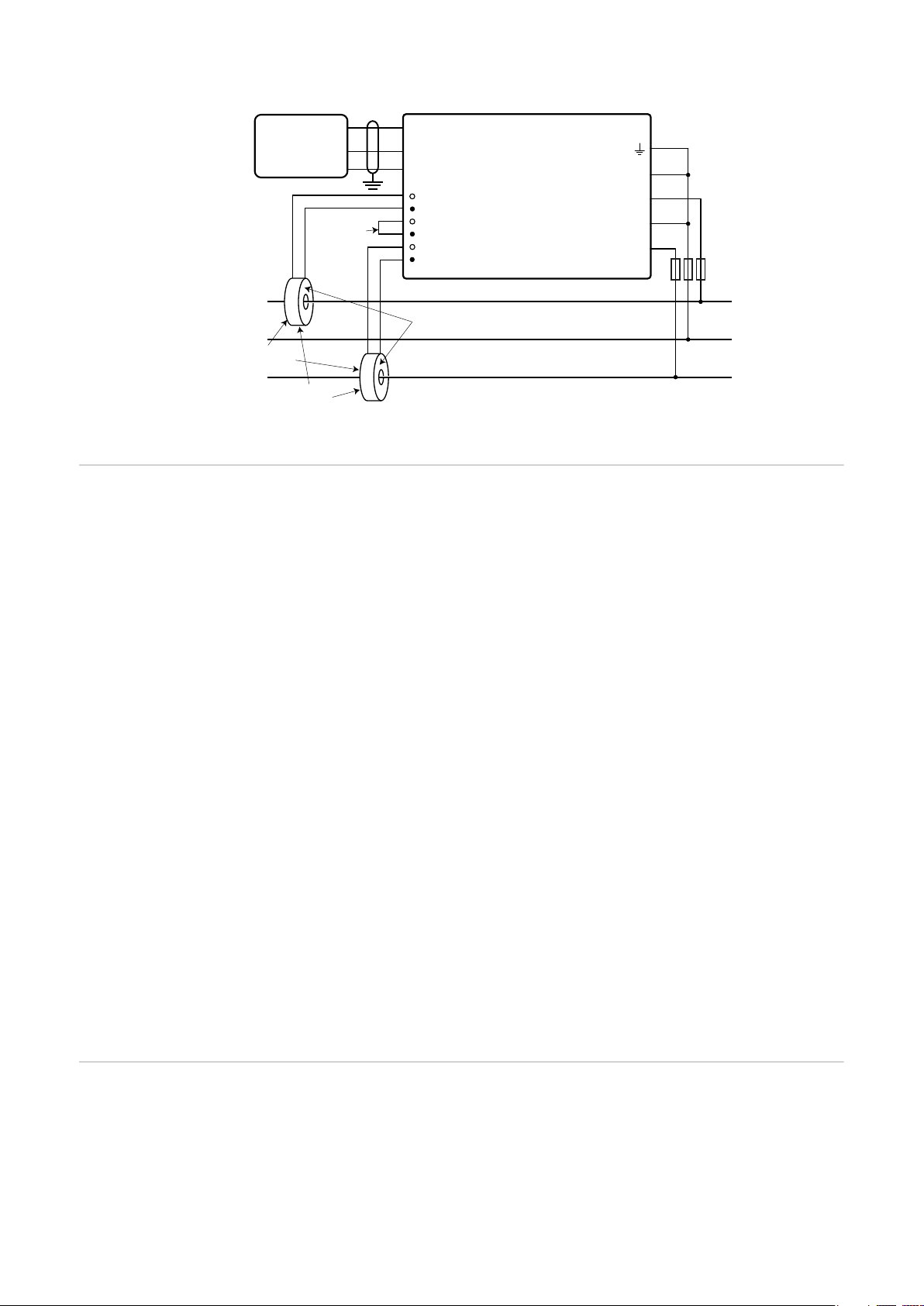
Three-Phase Two-Wire Corner Grounded Delta (only 240V-3 and 480V-3)
Connect Current
Transformers
Fronius
Datama-
nager
LOAD
Load
Faces
Tran sformers
WHITE
BLACK
Current
D-
D+
-
Shorting
Jumper
WHITE
D-
D+
-
BLACK
Source
Fronius Smart Meter
CT L1
CT L2
CT L3
Faces
N
L1
L2
L3
Fuses or
Breaker ≤ 20 A
Phase L1
Phase L2
(Ground)
LINE
Phase L3
The current transformer must generate 333.33 millivolts AC at rated current. See the current transformer data sheets for CT ratings.
- Do not use ratio or current output such as 1 amp or 5 amp output models!
- See the CT data sheets for the maximum input current ratings.
- Be careful to match the CTs with the voltage phases. Make sure the CT L1 is measuring the current on the same phase being monitored by the L1 voltage input and the
same for phases L2 and L3. Use the supplied colored labels or colored tape to identify
the CT leads.
- To minimize current measurement noise, avoid extending the CT wires, especially in
noisy environments. If it is necessary to extend the wires, use twisted pair cable 22 to
14 AWG, rated for 300 V or 600 V (not less than the service voltage) and shielded if
possible
- Make sure the CTs face the correct direction. An arrow might indicate either the load
or the source (public grid)
- If you see strange readings on unused phases, jumper the unused CT inputs: for each
unused CT, connect a short cable from the terminal marked with a white dot to the terminal marked with a black dot.
Install the CTs around the conductor to be measured and connect the CT leads to the Fronius Smart Meter. Always turn off power before disconnecting any live conductors. Put the
line conductors through the CTs as shown in the previous section.
CTs are directional. If they are mounted backwards or with their white and black wires
swapped the measured power will be negative. The status LEDs indicate negative measured power by flashing red.
Split-core CTs can be opened for installation around the conductor. A nylon cable tie may
be secured around the CT to prevent inadvertent opening.
CT Wiring The current transformers connect to the six position black screw terminal block. Connect
the white and black CT wires to the Fronius Smart Meter terminals marked CT L1, CT L2
and CT L3. Excess length may be trimmed from the wires if desired. Connect each CT with
the white wire aligned with the white dot on the label and the black wire aligned with the
black dot. Note the order in which the phases are connected, as the line voltage phases
must match the current phases for accurate power measurement.
14
Page 15

Connecting the
Data Communication Signals
- Connect the Data Communication Terminal from the Fronius Smart Meter to the Fronius Inverter
- D+ to D+
- D- to D-
- - to -
EN-US
Terminating Resistors
1
3
5
7
9
0
2
4
6
8
I IO RS485
- The Fronius Solar Meter outputs are electrically isolated from dangerous voltages.
- If the output wiring is near line voltage wiring, use wires or cables with a 300 V or 600
V rating (never less than the service voltage).
- If the output wiring is near bare conductors, it should be double insulated or jacketed.
- You may install two wires into each screw terminal by twisting the wires together, inserting them into the terminal and tightening them securely. Note: a loose wire can disable an entire network section.
- Use shielded twisted-pair cable to prevent interference. If there is no common conductor, connect the shield to the - (respectively C) terminal.
- Shielded 24 AWG Cat5, Cat5e or 23-24 AWG Cat6 cable is acceptable.
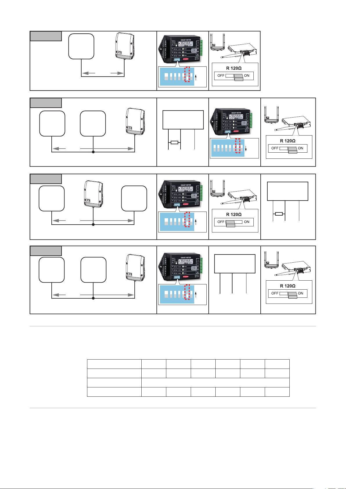
The system might work without terminating resistors. Due to interferences, the use of terminating resistors according to the following schemes are recommended.
D-
-
D+
+
+
15
Page 16
OPTION 1
OPTION 1
OPTION 3
OPTION 4
OPTION 2
Fronius
Smart
Meter
OPTION 2
Modbus
RTU
Slave
OPTION 3
Fronius
Smart
Meter
max.
300 m
Data (Recommended cable:
Li2YCY(TP) or CAT6a)
Fronius
Smart
Meter
max.
300 m
Data (Recommended cable:
Li2YCY(TP) or CAT6a)
Modbus
max.
300 m
Data (Recommended cable:
Li2YCY(TP) or CAT6a)
RTU
Slave
1 2 3 4 5 6 7 8
CTS 206-8 T517
Modbus RTU
Slave
D- / D+ -
120 Ω
*)
1 2 3 4 5 6 7 8
CTS 206-8 T517
PIN7
ON
PIN7
ON
1 2 3 4 5 6 7 8
CTS 206-8 T517
PIN7
OFF
Modbus RTU
Slave
D- / D+ -
120 Ω
*)
OPTION 4
Modbus RTU
Fronius
Smart
Meter
Modbus
RTU
Slave
max.
300 m
Data (Recommended cable:
1 2 3 4 5 6 7 8
CTS 206-8 T517
PIN7
ON
Slave
D- / D+ -
Li2YCY(TP) or CAT6a)
Modbus RTU The Fronius Smart Meter must be connected to the Fronius Datamanager. If only one Fro-
nius Smart Meter is installed, the Modbus Address is 1.
DIP Switch 1 2 3 4 5 6
Up (1) value 1 2 4 8 16 32
Address Modbus Address 1
Position 1, Up 0, Down 0, Down 0, Down 0, Down 0, Down
Set Terminating
Resistor
16
Select the state of the terminating resistor by setting DIP switch Down (= terminating resistor OFF) or Up (= terminating resistor ON).
Page 17
DIP Switch 7
Position 0, Down - Terminating resistor = OFF
1, Up - Terminating resistor = ON
Set Baud Rate Select the baud rate by setting DIP switch position 8 (see below). The change will take ef-
fect immediately.
Baud Rate DIP Switch 8
9600 (default) 0, Down
EN-US
Configuration
Web Interface
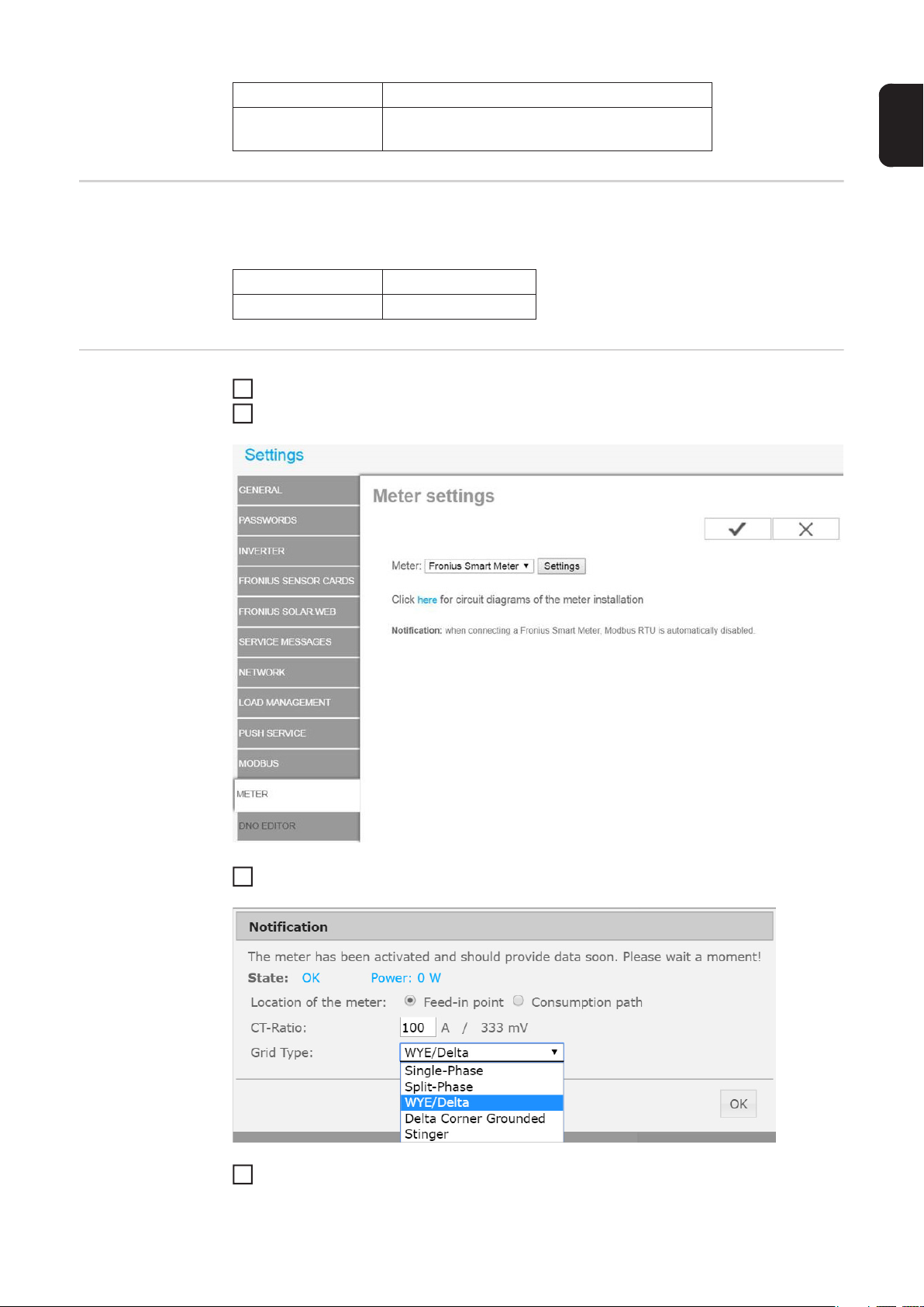
Go to the web interface of the Fronius Datamanager in Settings - Meter - Settings
1
Select “Fronius Smart Meter“
2
Click “Settings“
3
Set Location of the meter, CT-Ratio and Grid Type
4
17
Page 18
Operation
Power Status
LEDs
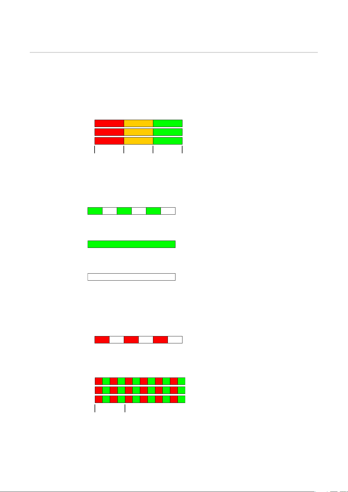
The three status LEDs on the front of the Fronius Smart Meter can help indicate correct
measurements and operation. The “L1”, “L2”, and “L3” on the diagrams indicate the three
phases:
Normal Startup
The Fronius Smart Meter displays the following startup sequence whenever power is first
applied.
A
B
C
1.0sec1.0sec
GreenYel lowRed
GreenYel lowRed
GreenYel lowRed
1.0sec
Consuming Power
Any phase with the LEDs flashing green is indicating normal positive power (Import of
energy from public grid).
If the inverter or any other power source is not producing power and some minimal power
is being used, the LEDs should be flashing green. This is normal, when the inverter is in
its 5 minute startup cycle.
Green
Off
Green
Off
Green
Off
No Power
Any phase with a solid green LED indicates no power, but line voltage is present.
Green
No Voltage
Any phase LED that is off indicates no voltage on that phase.
Off
Generating Power
Red flashing indicates negative power for that phase. This is a normal behavior if more
power is produced (by the inverter or any other power source) than consumed (Export of
energy to the public grid). If no power is produced at all, this might indicate either reversed CT's, swapped CT wires or CT's are not matched with the correct line voltage
phase.
C
Red
Off
Red
Off
Red
Off
Overvoltage Warning
The following indicates that the line voltage is too high for this model. Disconnect power
immediately! Check the line voltages and the meter ratings (in the white box on the label).
GR GR GR GR GR GR
A
GR GR GR GR
B
GR GR GR GR
C
1.0sec
GR GR
GR GR
18
Page 19

Meter Not Operating
If none of the LEDs are illuminated, check that the correct line voltages are applied to the
meter. If the voltages are correct, call customer service for assistance.
A
B
C
Off
Off
Off
Error
If the meter experiences an internal error, all LEDs will light up red for 3 or more seconds.
If you see this happen repeatedly, return the meter for service.
EN-US
Modbus Communication LEDs
A
B
C
Red
Red
Red
3.0sec
Near the upper left corner, there is a diagnostic Com (communication) LED that can indicate the following:
Green Off
Yel low Off
Red
YR YR YR
Red
A short green flash indicates a valid packet addressed to this
device.
Short yellow flashes or rapid flashing indicate valid packets addressed to different devices.
A one-second red flash indicates an invalid packet: bad baud
rate, bad CRC, noise, bad parity, etc.
Rapid red/yellow flashing indicates a possible address conflict
(two devices with the same DIP switch address).
Solid red indicates the address is set to zero: an invalid choice.
19
Page 20
Technical Data
Accuracy Normal Operation
Line voltage: -20% to +15% of nominal
Power factor: 1.0
Frequency: 48 - 62 Hz
Ambient Temperature: 23° C ± 5° C
CT Current: 5% - 100% of rated current
Accuracy: ± 0.5% of reading
Measurement Update Rate: 0.1 second. Internally, all measurements are performed at this rate.
Startup Time: ~1.0 second. The Fronius Smart Meter starts communicating this long after
AC voltage is applied. Energy measurement starts 50-100 milliseconds after AC is applied.
Default CT Phase Angle Correction: 0.0 degrees.
Models and Electrical
Meter Service
Type
240V-3 UL 120 208-240 1 - 3 2 - 4
480V-3 UL 277 480 1 - 3 2 - 4
600V-3 UL 347 600 1 - 3 2 - 4
The Fronius Smart Meter has an optional neutral connection that may be used for measuring wye circuits. In the absence of neutral, voltages are measured with respect to ground.
The Fronius Smart Meter uses the phase L1 (øA) and phase L2 (øB) connections for power.
Over-Voltage Limit: 125% of nominal Vac. Extended over-voltage operation can damage
the Fronius Smart Meter and void the warranty.
Over-Current Limit: 120% of rated current. Exceeding 120% of rated current will not harm
the Fronius Smart Meter but the current and power will not be measured accurately.
Maximum Surge: 4 kV according to EN 61000-4-5
Power Consumption: The following table shows maximum volt-amperes, the power sup-
ply ranges, typical power consumption, and typical power factors with all three phases
powered at nominal line voltages. The power supply consumes most of the total power,
while the measurement circuitry draws 1-10% of the total (6-96 milliwatts per phase, depending on the model). Due to the design of the power supply, the Fronius Smart Meter
draws slightly more power at 50 Hz.
Nominal Vac
Line-to-Neutral
Nominal Vac
Line-to-Line
Phases Wires
20
Meter Ser-
vice Type
240V-3 UL 1.2 W 1.5 W 0.70 4 VA 166 - 276 L1 and L2
480V-3 UL 1.2 W 1.6 W 0.70 3 VA 384 - 552 L1 and L2
600V-3 UL 1.0 W 1.3 W 0.76 3 VA 278 - 399 N and L1
*) The Rated VA is the maximum at 115% of nominal Vac at 50 Hz. This is the same as the
value that appears on the front label of the Fronius Smart Meter.
Maximum Power Supply Voltage Range: -20% to +15% of nominal (see table above).
For the 3D-240 service, this is -20% of 208 Vac (166 Vac) to +15% of 240 Vac (276 Vac).
Operating Frequencies: 50 / 60 Hz
Measurement Category: CAT III
Real Pow-
er (60 Hz)
Real Pow-
er (50 Hz)
Power
Factor
(50 Hz)
Rated
VA *)
Power Supply
Range (Vac)
Power Sup-
ply Terminals
Page 21
Measurement category III is for measurements performed in the building installation. Examples are measurements on distribution boards, circuit breakers, wiring, including cables, bus bars, junction boxes, switches, socket outlets in the fixed installation, and
equipment for industrial use and some other equipment, for example, stationary motors
with permanent connection to the fixed installation.
The line voltage measurement terminals on the meter are rated for the following CAT III
voltages (these ratings appear on the front label):
Meter Service Type CAT III Voltage Rating
240V-3 UL 120
480V-3 UL 277
600V-3 UL 600
Current Transformer Inputs:
Nominal Input Voltage (At CT Rated Current): 0.33333 Vac RMS
Absolute Maximum Input Voltage: 5.0 Vac RMS
Input Impedance at 50/60 Hz: 23 kOhm
Certifications Safety: UL 61010-1, CAN/CSA-C22.2 No. 61010-1-04, IEC 61010-1
Immunity: EN 61326: 2002 (Industrial Locations)
Electrostatic Discharge: EN 61000-4-2
Radiated RF Immunity: EN 61000-4-3
Electrical Fast Transient / Burst: EN 61000-4-4
Surge Immunity: EN 61000-4-5
Conducted RF Immunity: EN 61000-4-6
Voltage Dips, Interrupts: EN 61000-4-11
Emissions: FCC Part 15, Class B, EN 55022: 1994, Class B
EN-US
Environmental Operating Temperature: -30° C to +75° C (-22° F to 167° F)
Altitude: Up to 2000 m (6560 ft)
Operating Humidity: non-condensing, 5 to 90% relative humidity (RH) up to 40°C, de-
creasing linearly to 50% RH at 55°C
Pollution: POLLUTION DEGREE 2 - Normally only non-conductive pollution; occasionally, a temporary conductivity caused by condensation must be expected.
Indoor Use: Suitable for indoor use
Outdoor Use: Suitable for outdoor use if mounted inside an electrical enclosure (Ham-
mond Mfg., Type EJ Series) rated NEMA 3R or 4 (IP 66).
Mechanical Enclosure: High impact, ABS/PC plastic
Flame Resistance Rating: UL 94V-0, IEC FV-0
Size: 6.02 in. × 3.35 in. × 1.50 in. (153 mm × 85 mm × 38 mm)
Connectors: Euroblock pluggable terminal blocks
Green: up to 12 AWG (2.5 mm²), 600 V
Black: up to 12 AWG (2.5 mm²), 300 V
Fronius Manufacturer's Warranty
Detailed warranty terms and conditions specific to your country can be found online:
www.fronius.com/solar/warranty
To take advantage of the full warranty duration for your newly installed Fronius inverter or
accumulator, register your product at: www.solarweb.com.
21
Page 22

22
Page 23
Estimado lector
Introducción Le agradecemos su confianza y queremos felicitarle por la adquisición de este producto
de Fronius de alta calidad técnica. El presente manual le ayudará a familiarizarse con el
producto. Si lee detenidamente este manual, aprenderá las numerosas posibilidades que
le ofrece su producto Fronius. Solo así podrá aprovechar todas sus ventajas.
Tenga en cuenta también las normas de seguridad para conseguir una mayor seguridad
en el lugar en el que emplee el producto. Un manejo cuidadoso de su producto ayuda a
conseguir una calidad y fiabilidad duraderas. Todo ello constituye la condición previa
esencial para lograr unos resultados excelentes.
ES
Explicación de
las indicaciones
de seguridad
¡PELIGRO! Indica un peligro inminente. Si no se evita este peligro, las conse-
cuencias son la muerte o lesiones de carácter muy grave.
¡ADVERTENCIA! Indica una situación posiblemente peligrosa. Si no se evita
esta situación, las consecuencias pueden ser la muerte y lesiones de carácter
muy grave.
¡PRECAUCIÓN! Indica una situación posiblemente perjudicial. Si no se evita
esta situación, se pueden producir lesiones de carácter leve o insignificantes, así
como daños materiales.
¡OBSERVACIÓN! Indica la posibilidad de obtener unos resultados mermados de
trabajo y que se puedan producir daños en el equipamiento.
¡IMPORTANTE! Indica consejos de aplicación y otra información especialmente útil. No
se trata de una palabra señaladora que indica una situación perjudicial o peligrosa.
Cuando vea uno de los símbolos representados en el capítulo "Indicaciones de seguridad", se requiere un mayor grado de atención.
23
Page 24

24
Page 25

Tabla de contenido
Normativa de seguridad............................................................................................................................. 27
Generalidades....................................................................................................................................... 27
Condiciones ambientales...................................................................................................................... 27
Personal cualificado.............................................................................................................................. 28
Derechos de autor ................................................................................................................................ 28
Protección de datos .............................................................................................................................. 28
FCC / RSS Compliance ........................................................................................................................ 29
Advertencias en el equipo..................................................................................................................... 29
Instalación.................................................................................................................................................. 30
Lista de comprobación para la instalación............................................................................................ 30
Montaje ................................................................................................................................................. 30
Protección del circuito de corriente....................................................................................................... 31
Cableado de la línea............................................................................................................................. 31
Conectar los transformadores de corriente........................................................................................... 34
Cableado TC......................................................................................................................................... 34
Conexión de las señales de comunicación de datos............................................................................ 35
Resistencias de terminación................................................................................................................. 35
Modbus RTU......................................................................................................................................... 36
Ajustar la resistencia de terminación .................................................................................................... 36
Ajustar el número de baudios ............................................................................................................... 37
Configuración del interface web............................................................................................................ 37
Manejo ....................................................................................................................................................... 38
LED de estado de alimentación............................................................................................................ 38
LED de comunicación Modbus ............................................................................................................. 39
Datos técnicos ........................................................................................................................................... 40
Precisión ............................................................................................................................................... 40
Medición................................................................................................................................................ 40
Modelos y sistema eléctrico.................................................................................................................. 40
Certificaciones ...................................................................................................................................... 41
Medioambiental..................................................................................................................................... 41
Mecánica............................................................................................................................................... 41
Garantía de fábrica de Fronius ............................................................................................................. 42
ES
25
Page 26

26
Page 27
Normativa de seguridad
Generalidades
El equipo ha sido fabricado según el estado de la técnica y las reglas reconocidas en referencia a la seguridad. No obstante, el manejo incorrecto o el uso
inadecuado implica peligro para:
- La integridad física y la vida del operario o de terceras personas.
- El equipo y otros valores materiales de la empresa explotadora.
- El trabajo eficiente con el equipo.
Todas las personas implicadas en la puesta en servicio, el mantenimiento y la
conservación del equipo deben:
- Poseer la cualificación correspondiente.
- Poseer conocimientos en el manejo de instalaciones eléctricas.
- Leer completamente y seguir escrupulosamente este manual de instrucciones.
El manual de instrucciones debe permanecer guardado en el lugar de empleo
del equipo. Complementariamente al manual de instrucciones, se deben tener en cuenta las reglas válidas a modo general, así como las reglas locales
respecto a la prevención de accidentes y la protección medioambiental.
Todas las instrucciones de seguridad y peligro en el equipo:
- Se deben mantener en estado legible.
- No se deben dañar.
- No se deben retirar.
- No se deben tapar ni cubrir con pegamento o pintura.
Los bornes de conexión pueden alcanzar temperaturas elevadas.
Solo se deberá utilizar el equipo cuando todos los dispositivos de seguridad
tengan plena capacidad de funcionamiento. Si los dispositivos de seguridad
no disponen de plena capacidad de funcionamiento existe peligro para:
- La integridad física y la vida del operario o de terceras personas.
- El equipo y otros valores materiales de la empresa explotadora.
- El trabajo eficiente con el equipo.
Antes de conectar el equipo, encomendar a un taller especializado y autorizado la reparación de los dispositivos de seguridad que no dispongan de plena
capacidad de funcionamiento.
Jamás se deben anular ni poner fuera de servicio los dispositivos de seguridad.
La ubicación de las instrucciones de seguridad y peligro en el equipo figura en
el capítulo "Generalidades" del manual de instrucciones del equipo.
Antes de conectar el equipo, eliminar las incidencias que puedan mermar la
seguridad.
¡Se trata de su seguridad!
ES
Condiciones ambientales
Cualquier servicio o almacenamiento del equipo fuera del campo indicado
será considerado como no previsto. El fabricante declina cualquier responsabilidad frente a los daños que se pudieran originar.
En los datos técnicos del manual de instrucciones figura información detallada
acerca de las condiciones ambientales admisibles.
27
Page 28
Personal cualificado
La información de servicio en este manual de instrucciones está destinada exclusivamente a personal técnico cualificado. Las descargas eléctricas pueden
ser mortales. No realizar actividades diferentes a las que se indican en la documentación. Lo mismo es aplicable cuando el personal está cualificado a tal
fin.
Todos los cables y líneas deben estar fijados, intactos, aislados y tener una
dimensión suficiente. Las uniones sueltas, y los cables y líneas chamuscados,
dañados o con una dimensión insuficiente deben ser reparados inmediatamente por un taller especializado autorizado.
Únicamente un taller especializado autorizado debe llevar a cambo el mantenimiento y la reparación.
En caso de piezas procedentes de otros fabricantes no queda garantizado
que hayan sido diseñadas y fabricadas de acuerdo con las exigencias y la seguridad. Utilizar solo repuestos originales (lo mismo es aplicable a piezas normalizadas).
No se deben efectuar cambios, montajes ni transformaciones en el equipo, sin
previa autorización del fabricante.
Se deben sustituir inmediatamente los componentes que no se encuentren en
perfecto estado.
Derechos de autor
Protección de datos
Los derechos de autor respecto al presente manual de instrucciones son propiedad del fabricante.
El texto y las ilustraciones corresponden al estado de la técnica en el momento de la impresión. Reservado el derecho a modificaciones. El contenido del
manual de instrucciones no justifica ningún tipo de derecho por parte del comprador. Agradecemos cualquier propuesta de mejora e indicaciones respecto
a errores en el manual de instrucciones.
El usuario es responsable de la salvaguardia de datos de las modificaciones
frente a los ajustes de fábrica. El fabricante no es responsable en caso de que
se borren los ajustes personales.
28
Page 29

FCC / RSS Compliance
FCC
Este equipo ha sido verificado y cumple los valores límite de un equipo digital de la clase B según la parte 15 de las disposiciones FCC. Estos valores
límite pretenden garantizar una protección adecuada frente a perturbaciones perjudiciales en espacios residenciales. Este equipo genera y utiliza
energía de alta frecuencia y puede provocar incidencias en la radiocomunicación cuando no es utilizado de acuerdo con las instrucciones. No obstante, no existe ninguna garantía de que las incidencias no aparezcan en una
determinada instalación.
Si este equipo produce incidencias en la recepción de radio o televisión que
pueden detectarse apagando y volviendo a encender el equipo, se recomienda al usuario eliminar las incidencias aplicando una o varias de las siguientes medidas:
- Alinear o cambiar el posicionamiento de la antena receptora.
- Incrementar la distancia entre el equipo y el receptor.
- Conectar el equipo a otro circuito de corriente al que no está conectado
el receptor.
- Para más ayuda rogamos que se ponga en contacto con el distribuidor
o un técnico experimentado en radio y televisión.
Industry Canada RSS
Este equipo cumple las normas Industry Canada RSS libres de licencia. El
servicio está sujeto a las siguientes condiciones:
(1) El equipo no debe originar perturbaciones.
(2) El equipo debe ser capaz de soportar cualquier perturbación, incluidas
las que puedan originar una merma del servicio.
ES
Advertencias en
el equipo
Símbolos de seguridad
Para evitar descargas eléctricas
- No desarmar ni modificar
- No introducir agua en el equipo
- No introducir material extraño en el equipo
- No intervenir en las conexiones directamente
RCM icono - El producto cumple con las leyes australianas.
29
Page 30

Instalación
Lista de comprobación para la
instalación
Para los detalles de la instalación, ver las secciones a las que se hace referencia:
Desconectar la alimentación antes de establecer las conexiones de tensión de línea.
1
Montar el Fronius Smart Meter (ver "Montaje").
2
Conectar los disyuntores automáticos o fusibles y los desconectores (ver "Protección
3
del circuito de corriente").
Conectar los cables de tensión de línea al bloque de bornes del contador (ver "Ca-
4
bleado de la línea").
Montar los transformadores de corriente (TC) alrededor de los conductores de línea.
5
Asegurarse de que los CT están orientados correctamente. Podría haber una flecha
indicando la carga o la fuente (red pública) (ver "Conectar los transformadores de corriente").
Conectar los cables trenzados blanco y negro de los TC al bloque de bornes en el
6
contador, haciendo que los colores de cable coincidan con los puntos blanco y negro
en la etiqueta del contador ("Cableado de los TC").
Comprobar que las fases de los TC coincidan con las fases de tensión de línea (ver
7
"Conectar los transformadores de corriente").
Registrar la corriente nominal TC de cada contador, ya que se requerirá durante la
8
configuración.
Conectar los bornes de salida del Fronius Smart Meter al equipo de monitorización
9
(ver "Conexión de las señales de comunicación de datos").
En caso necesario, ajustar las resistencias de terminación (ver "Resistencias de ter-
10
minación")
Comprobar que todos los cables y enchufes estén bien instalados en los bloques de
11
bornes tirando de cada cable.
Encender el Smart Meter.
12
Verificar que los LED indican el funcionamiento correcto. Si se consume potencia y
13
todas las fuentes de corriente están desconectadas, los LED de las fases utilizadas
deberían parpadear en verde (ver "Manejo").
Comprobar el software de monitorización de instalaciones Fronius. Para garantizar la
14
compatibilidad entre el inversor y el Smart Meter, siempre se debe mantener actualizado el software. Las actualizaciones pueden realizarse mediante la página web del
inversor.
Ajustar "CT-Ratio" (Ratio TC) y Grid Type (tipo de red) en el interface web del Fronius
15
Datamanager en "Settings" - Meter" - "Settings" Ajustes - Contador - Ajustes) (ver
"Configuración del interface web").
Montaje El Fronius Smart Meter dispone de dos agujeros de montaje con una distancia de 5.375
in. (137 mm) entre cada uno (de centro a centro). Estos agujeros de montaje están normalmente tapados por los bornes de tornillo desmontables. Quitar los bornes de tornillo
para marcar las posiciones de los agujeros y montar el contador.
Se incluyen tornillos metálicos de rosca cortante. No apretar en exceso los tornillos, ya que
una tensión prolongada en la caja puede provocar fisuras.
30
Page 31

153 mm (6.02 in)
85.1 mm (3.35 in)
Protección del
circuito de corriente
Ø
9.8 mm (0.386 in)
136.6 mm (5.375 in)
Ø
5.1 mm (0.200 in)
38 mm (1.50 in) High
El Fronius Smart Meter se considera un "equipo permanentemente conectado" y requiere
un medio de desconexión (disyuntor automático, interruptor o desconector) y una protección contra exceso de corriente (fusible o disyuntor automático).
El Fronius Smart Meter solo proporciona 10-30 mA, por lo que el servicio nominal de todos
los interruptores, desconectores, fusibles y/o disyuntores automáticos se determina por el
calibre, la tensión de red y el valor nominal requerido para interrumpir la corriente.
- El interruptor, el desconector o el disyuntor automático deben estar a la vista, lo más
cerca posible del Fronius Smart Meter, y deben poder manejarse con facilidad.
- Utilizar disyuntores automáticos o fusibles especificados para 20 amperios o menos.
- Cuando se vaya a monitorizar más de una tensión de línea, utilizar disyuntores automáticos acoplados.
- Los disyuntores automáticos o fusibles deben proteger los bornes de red etiquetados
como L1, L2 y L3. Rara vez, en casos en los que el neutro tiene protección contra exceso de corriente, el protector contra exceso de corriente debe interrumpir simultáneamente ambos conductores, es decir, el neutro y el que no está conectado a tierra.
- La protección del circuito de corriente/sistema de desconectores debe cumplir IEC
60947-1 y IEC 60947-3, así como la normativa eléctrica nacional y local.
ES
Cableado de la línea
- Siempre desconectar la alimentación antes de conectar las entradas de tensión de línea al Fronius Smart Meter.
- Para los cables de tensión de línea, se recomiendan cables trenzados de 16 a 12
AWG, tipo THHN, MTW o THWN, 600 V.
- No sustituir más de un cable por cada borne de tornillo; utilizar tuercas de cable o bloques de bornes por separado, en caso necesario.
- Verificar que las tensiones de línea coinciden con los valores de línea a línea y de línea a neutro impresos en el cuadro blanco de la etiqueta frontal.
Conectar cada conductor a la fase apropiada; conectar también un conductor de tierra y
uno neutro (según sea necesario). La conexión neutra "N" no se requiere en los modelos
delta, aunque recomendamos conectarla a tierra si no hay neutro.
El borne de tornillo permite cables de hasta 12 AWG. Conectar cada línea de tensión al
bloque de bornes verde, según se muestra en las siguientes figuras. Una vez conectadas
las líneas de tensión, asegurarse de que ambos bloques de bornes estén completamente
asentados en el Fronius Smart Meter.
31
Page 32
Al suministrar energía por primera vez, comprobar que el comportamiento de los LED es
correcto. ¡Si se percibe que los LED parpadean en rojo-verde-rojo-verde, significa que la
tensión es excesiva para el modelo en cuestión, por lo tanto, desconectar inmediatamente
el interruptor de alimentación!
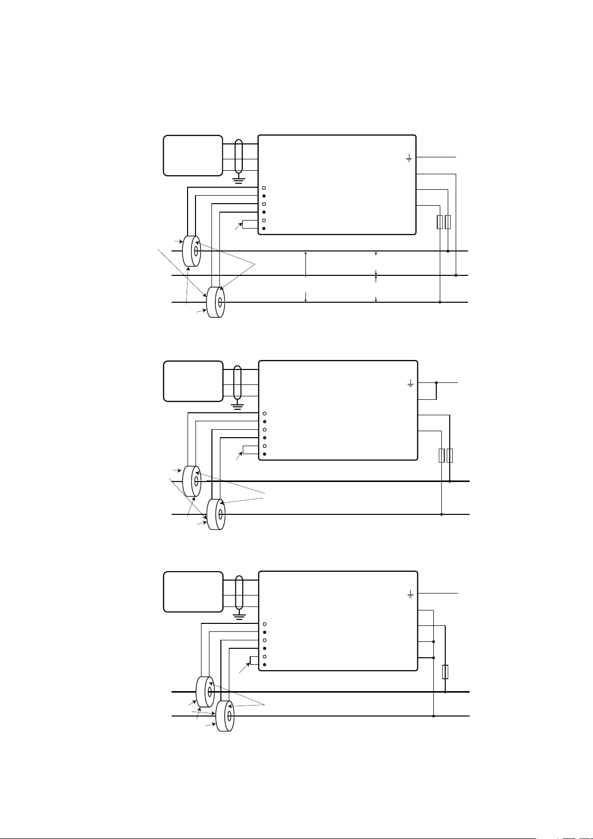
Tres cables monofásicos (punto medio neutro)
Fronius
Datama-
nager
WHITE
Load
Faces
LOAD
Current
Tran sformers
D-
D+
-
WHITE
BLACK
BLACK
Shorting
Jumper
D-
D+
-
CT L1
CT L2
CT L3
Source
Faces
e.g. 120 Vac (US),
240 Vac (AUS)
Fronius Smart Meter
N
L1
L2
L3
e.g. 120 Vac (US),
240 Vac (AUS)
e.g. 120 Vac (US),
240 Vac (AUS)
Dos cables monofásicos sin neutro (Sólo 240V-3 y 480V-3)
Fronius
Datama-
nager
WHITE
Load
Faces
LOAD
Current
Tran sformers
D-
D+
-
WHITE
BLACK
BLACK
Shorting
Jumper
D-
D+
-
CT L1
CT L2
CT L3
Source
Faces
Fronius Smart Meter
N
L1
L2
L3
Ground
Fuses or
Breaker ≤ 20 A
Phase L1
Neutral
Phase L2
Ground
Fuses or
Breaker ≤ 20 A
Phase L1
Phase L2
LINE
LINE
32
Dos cables monofásicos con neutro
Fronius
Datama-
nager
LOAD
Load
Faces
Current
Tran sformers
D-
D+
-
WHITE
WHITE
BLACK
BLACK
Shorting
Jumper
D-
D+
-
CT L1
CT L2
CT L3
Source
Faces
Fronius Smart Meter
Ground
N
L1
L2
L3
Fuses or
Breaker ≤ 20 A
Phase L1
LINE
Neutral
Page 33
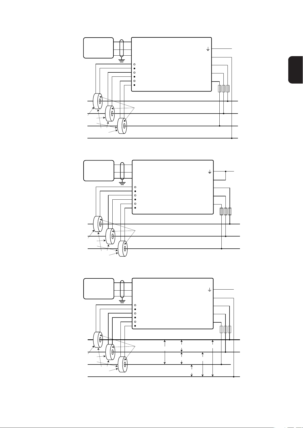
Tres cables trifásicos en estrella
Fronius
Datama-
nager
LOAD
Load
Faces
Tran sformers
WHITE
BLACK
Current
D-
D+
-
WHITE
BLACK
D-
Fronius Smart Meter
D+
-
CT L1
CT L2
CT L3
WHITE
BLACK
Source
Faces
N
L1
L2
L3
Tres cables trifásicos en delta sin neutro (Sólo 240V-3 y 480V-3)
Fronius
Datama-
nager
LOAD
Load
Faces
Tran sformers
WHITE
BLACK
Current
D-
D+
-
WHITE
BLACK
WHITE
D-
D+
-
BLACK
Source
Fronius Smart Meter
CT L1
CT L2
CT L3
Faces
N
L1
L2
L3
Ground
Fuses or
Breaker ≤ 20 A
Phase L1
Phase L2
Phase L3
Neutral
Ground
Fuses or
Breaker ≤ 20 A
Phase L1
Phase L2
Phase L3
ES
LINE
LINE
Tres cables trifásicos en punta
Fronius
Datama-
nager
LOAD
Load
Faces
Tran sformers
WHITE
BLACK
Current
D-
D+
-
WHITE
BLACK
WHITE
D-
D+
-
CT L1
CT L2
CT L3
BLACK
Source
Faces
Fronius Smart Meter
240 Vac
240 Vac
240 Vac 120 Va c
208 Vac
N
L1
L2
L3
120 Va c
Ground
Fuses or
Breaker ≤ 20 A
Phase L1
Phase L2
Phase L3
(Wild Leg)
Neutral
LINE
33
Page 34
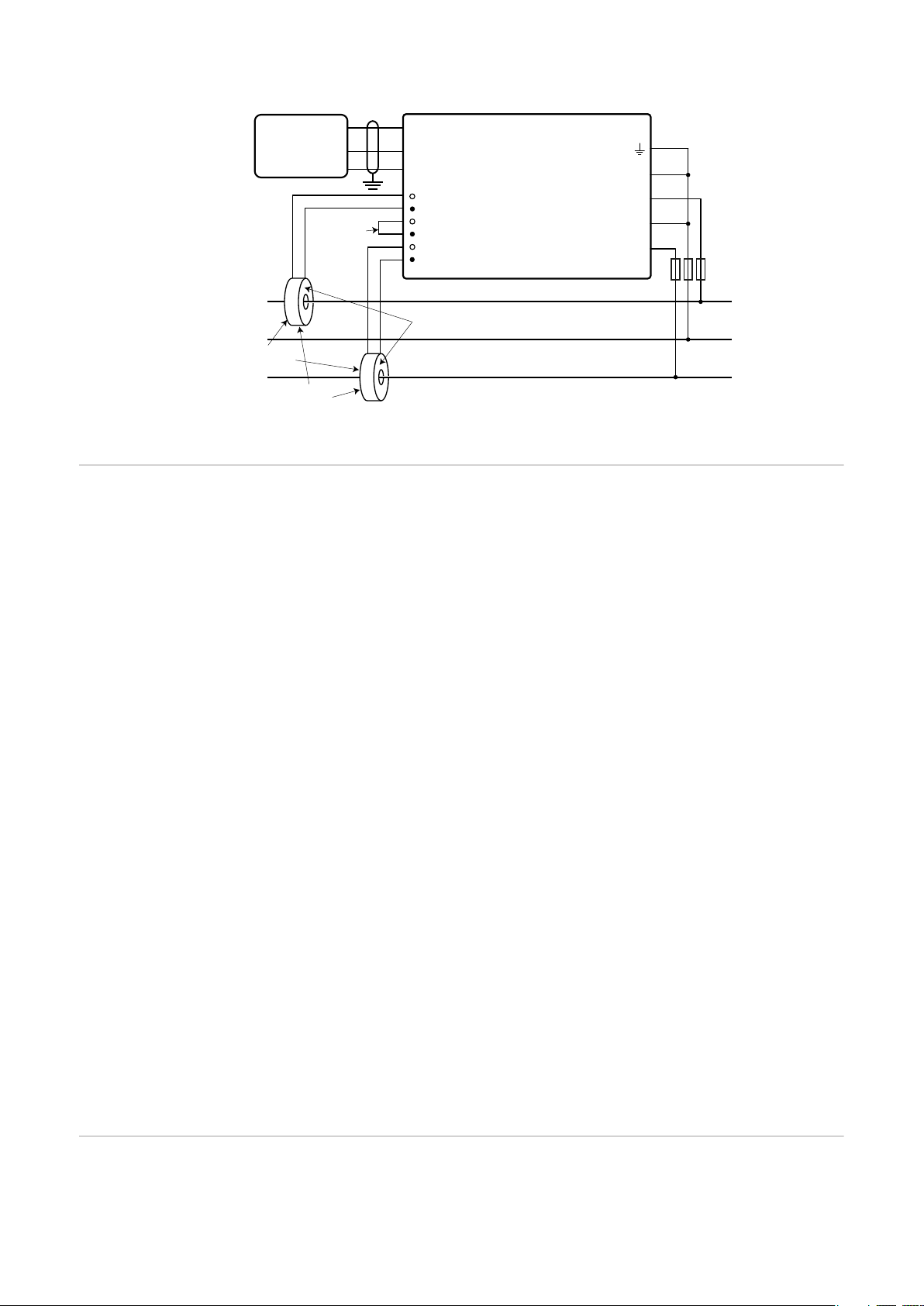
Dos cables trifásicos en delta puesto a tierra en esquina (Sólo 240V-3 y 480V-3)
Conectar los
transformadores
de corriente
Fronius
Datama-
nager
LOAD
Load
Faces
Tran sformers
WHITE
BLACK
Current
D-
D+
-
Shorting
Jumper
WHITE
D-
D+
-
BLACK
Source
Fronius Smart Meter
CT L1
CT L2
CT L3
Faces
N
L1
L2
L3
Fuses or
Breaker ≤ 20 A
Phase L1
Phase L2
(Ground)
LINE
Phase L3
El transformador de corriente debe generar 333.33 milivoltios CA a la corriente nominal.
Ver las fichas de datos del transformador de corriente para los valores nominales TC.
- ¡No utilizar el ratio ni la salida de corriente como para los modelos de salida de 1 amperio o 5 amperios!
- Ver las fichas de datos del TC para los valores nominales máximos para la corriente
de entrada.
- Prestar atención a que los TC coincidan con las fases de tensión. Asegurarse de que
TC L1 esté midiendo la corriente en la misma fase que está siendo monitorizada por
la entrada de tensión L1, lo mismo es aplicable para las fases L2 y L3. Utilizar las etiquetas de color suministradas o la cinta de color para identificar los cables TC.
- Para minimizar el ruido al medir la corriente, evitar tender los cables TC especialmente en entornos ruidosos. En caso de que sea necesario tender los cables, utilizar un
cable de par trenzado de 22 a 14 AWG, especificado para 300 V o 600 V (nunca menos que la tensión de servicio) y blindado en la medida de lo posible.
- Asegurarse de que los CT están orientados correctamente. Podría haber una flecha
indicando la carga o la fuente (red pública).
- En caso de que se detecten lecturas extrañas en las fases no utilizadas, puentear las
entradas TC no utilizadas: en cada TC no utilizada, conectar un cable corto desde el
borne marcado con un punto blanco hasta el borne marcado con un punto negro.
Instalar los TC alrededor del conductor que se va a medir y conectar los cables TC al Fronius Smart Meter. Siempre desconectar la alimentación antes de desconectar los conductores bajo tensión. Colocar los conductores de línea a través de los TC, según se muestra
en la sección anterior.
Los TC son direccionales. Si están montados hacia atrás o con sus cables negro y blanco
intercambiados, la potencia medida será negativa. Los LED de estado indican que se está
midiendo potencia negativa y parpadean en rojo.
Los TC de núcleo partido pueden abrirse para la instalación alrededor del conductor. Puede instalarse una sujeción de cables de nilón alrededor del TC para evitar que se abra accidentalmente.
Cableado TC Los transformadores de corriente están conectados al bloque de bornes de tornillo negro
de seis posiciones. Conectar los cables TC blanco y negro a los bornes del Fronius Smart
Meter marcados como CT L1, CT L2 y CT L3. La longitud sobrante de los cables puede
34
Page 35
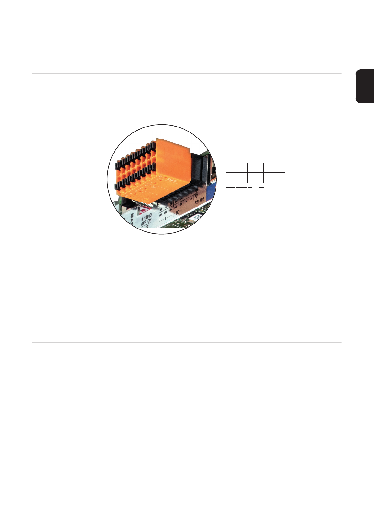
recortarse en caso deseado. Conectar cada TC con el cable blanco alineado con el punto
blanco en la etiqueta y el cable negro alineado con el punto negro. Observar el orden en
el que están conectadas las fases, ya que las fases de línea deben coincidir con las fases
de corriente para poder medir la potencia con precisión.
Conexión de las
señales de comunicación de datos
- Conectar el borne de comunicación de datos desde el Fronius Smart Meter al inversor
Fronius
- D+ a D+
- D- a D-
- - a -
1
3
5
7
9
0
2
4
6
8
I IO RS485
- Las salidas del Fronius Solar Meter están aisladas eléctricamente de tensiones peligrosas.
- Si el cableado de salida está cerca del cableado de tensión de línea, utilizar cables
especificados para 300 V o 600 V (nunca menos que la tensión de servicio).
- Si el cableado de salida está cerca de los conductores desnudos, debería tener doble
aislamiento o una vaina.
- Es posible instalar dos cables en cada borne de tornillo enroscándolos para insertarlos en el borne y, posteriormente, apretándolos bien. Observación: un cable suelto
puede habilitar toda una sección de red.
- Utilizar un cable de par trenzado blindado para evitar interferencias. Si no hay conductor común, conectar el blindado al borne - (respectivamente C).
- Es aceptable utilizar un cable blindado de 24 AWG Cat5, Cat5e o 23-24 AWG Cat6.
D-
-
D+
+
+
ES
Resistencias de
terminación
El sistema puede funcionar sin resistencias de terminación. Debido a las interferencias, se
recomienda utilizar resistencias de terminación según los siguientes esquemas.
35
Page 36
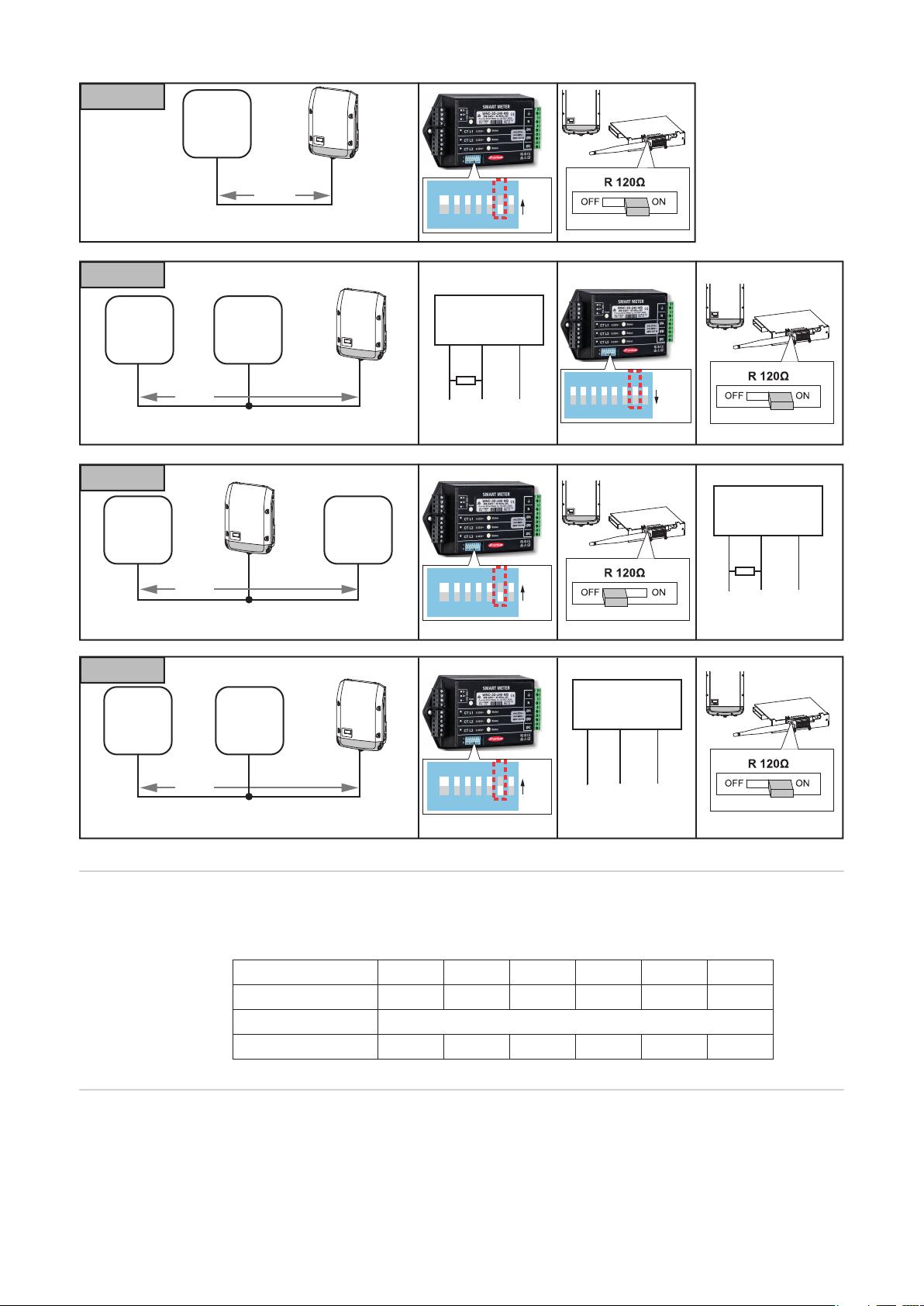
OPTION 1
OPTION 1
OPTION 3
OPTION 4
OPTION 2
Fronius
Smart
Meter
OPTION 2
Modbus
RTU
Slave
OPTION 3
Fronius
Smart
Meter
max.
300 m
Data (Recommended cable:
Li2YCY(TP) or CAT6a)
Fronius
Smart
Meter
max.
300 m
Data (Recommended cable:
Li2YCY(TP) or CAT6a)
Modbus
max.
300 m
Data (Recommended cable:
Li2YCY(TP) or CAT6a)
RTU
Slave
1 2 3 4 5 6 7 8
CTS 206-8 T517
Modbus RTU
Slave
D- / D+ -
120 Ω
*)
1 2 3 4 5 6 7 8
CTS 206-8 T517
PIN7
ON
PIN7
ON
1 2 3 4 5 6 7 8
CTS 206-8 T517
PIN7
OFF
Modbus RTU
Slave
D- / D+ -
120 Ω
*)
OPTION 4
Modbus RTU
Fronius
Smart
Meter
Modbus
RTU
Slave
max.
300 m
Data (Recommended cable:
1 2 3 4 5 6 7 8
CTS 206-8 T517
PIN7
ON
Slave
D- / D+ -
Li2YCY(TP) or CAT6a)
Modbus RTU El Fronius Smart Meter debe estar conectado al Fronius Datamanager. Si solo hay insta-
lado un Fronius Smart Meter, la dirección de Modbus es 1.
Interruptor DIP 1 2 3 4 5 6
Valor arriba (1) 1 2 4 8 16 32
Dirección Dirección de Modbus 1
Posición 1, arriba 0, abajo 0, abajo 0, abajo 0, abajo 0, abajo
Ajustar la resistencia de terminación
36
Seleccionar el estado de la resistencia de terminación ajustando el interruptor DIP en la
posición "Abajo" (= resistencia de terminación DES) o "Arriba" (= resistencia de terminación CON).
Page 37
Interruptor DIP 7
Posición 0, abajo - Resistencia de terminación = DES
1, arriba - resistencia de terminación = CON
Ajustar el número
de baudios
Configuración del
interface web
Seleccionar el número de baudios ajustando el interruptor DIP a la posición 8 (ver a continuación). El cambio tendrá efecto inmediato.
Número de baudios Interruptor DIP 8
9600 (predeterminado) 0, abajo
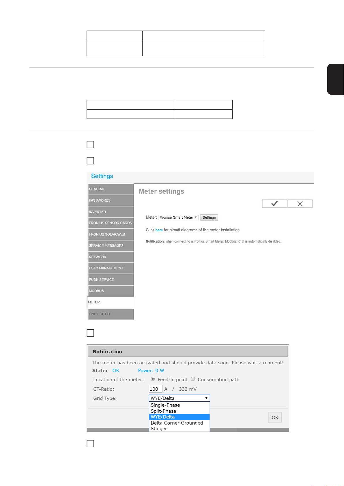
En el interface web del Fronius Datamanager, ir a "Settings" - "Meter" - "Settings"
1
(Ajustes - Contador - Ajustes).
Seleccionar "Fronius Smart Meter".
2
ES
Hacer clic en "Settings" (Ajustes)
3
Ajustar Location of the meter (Ubicación del contador), CT-Ratio (Ratio TC) y Grid
4
Type (Tipo de red)
37
Page 38

Manejo
LED de estado de
alimentación
Los tres LED de estado en frente del Fronius Smart Meter pueden ayudar a indicar las mediciones correctas y el funcionamiento correcto. En los diagramas, "L1", "L2" y "L3" indican
tres fases:
Normal Startup
(Puesta en servicio normal) El Fronius Smart Meter muestra la siguiente secuencia de
puesta en servicio siempre que se suministre energía por primera vez.
A
B
C
1.0sec1.0sec
GreenYel lowRed
GreenYel lowRed
GreenYel lowRed
1.0sec
Consuming Power
(Potencia consumida) Las fases cuyos LED parpadeen en verde indican potencia positiva (la energía se importa desde la red pública).
Si el inversor o cualquier otra fuente de corriente no están generando potencia y se está
utilizando cierta potencia mínima, los LED deberían parpadear en verde. Esto es normal
cuando el inversor está en el ciclo de puesta en servicio cuya duración es de 5 minutos.
Green
Off
Green
Off
Green
Off
No Power
(Sin potencia) Cualquier fase cuyo LED esté en verde indica que no hay potencia, pero
que sí hay tensión de línea.
Green
No Voltage
(Sin tensión) Cualquier LED que esté apagado indica que no hay tensión ni fase.
Off
Generating Power
(Generando potencia) Si el LED parpadea en rojo indica que hay potencia negativa en
la correspondiente fase. Se trata de un comportamiento normal si se está generando
más potencia (por el inversor o por cualquier otra fuente de corriente) que la consumida
(la energía se exporta a la red pública). Si no se genera potencia, puede indicar que los
TC están invertidos, los cables TC se han intercambiado o que los TC no coinciden con
la fase de tensión de línea correcta.
C
Red
Off
Red
Off
Red
Off
Overvoltage Warning
(Advertencia de sobretensión) Indica que la tensión de línea es excesiva para este modelo. ¡Desconectar inmediatamente la alimentación! Comprobar las tensiones de línea
y los valores nominales (en el cuadro blanco de la etiqueta frontal).
GR GR GR GR GR GR
A
GR GR GR GR
B
GR GR GR GR
C
1.0sec
GR GR
GR GR
38
Page 39
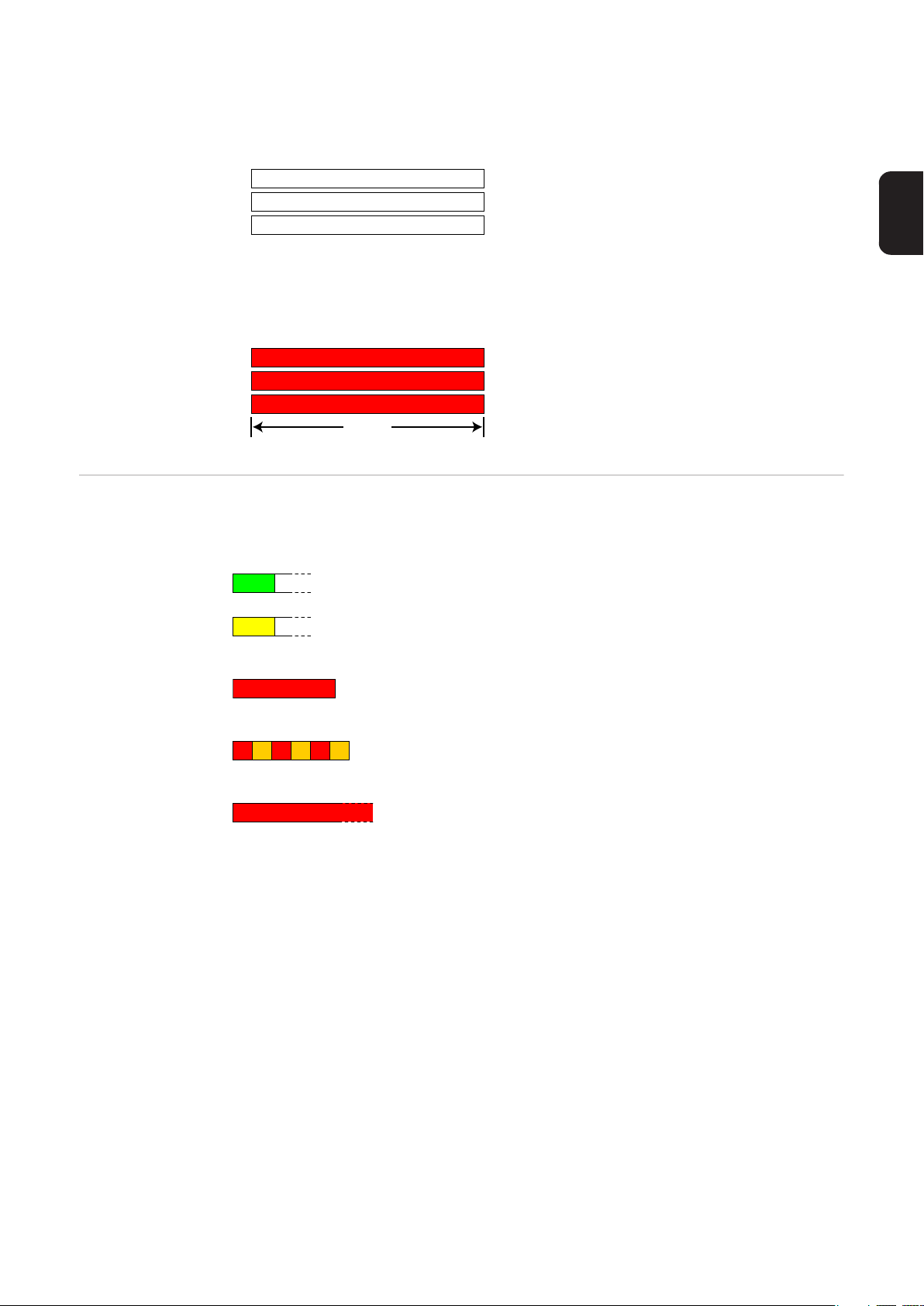
Meter Not Operating
(El contador no funciona) Si ninguno de los LED está iluminado, comprobar que se están
aplicando tensiones de línea correctas al contador. Si las tensiones son correctas, llamar al servicio de atención al cliente para recibir asistencia.
LED de comunicación Modbus
A
B
C
Off
Off
Off
Error
Si se ha producido un error interno en el contador, todos los LED se iluminarán en rojo
durante 3 segundos o más. Si el error persiste, enviar el contador para que sea comprobado.
A
B
C
Red
Red
Red
3.0sec
Cerca de la esquina superior izquierda hay un LED Com (comunicación) que indica lo siguiente:
Green Off
Yel low Off
Si parpadea brevemente en verde indica que se ha direccionado un paquete válido a este dispositivo.
Si parpadea brevemente en amarillo o parpadea rápido, indica
que se han direccionado paquetes válidos a diferentes dispositivos.
Red
Si parpadea en rojo durante un segundo, indica que hay un paquete no válido, número incorrecto de baudios, CRC incorrecto,
ruido, paridad incorrecta, etc.
YR YR YR
Si parpadea rápido en rojo/amarillo, indica un posible conflicto
de direcciones (dos dispositivos con la misma dirección de interruptor DIP).
Red
Si permanece en rojo indica que la dirección está ajustada a cero: no es un ajuste válido.
ES
39
Page 40

Datos técnicos
Precisión Funcionamiento normal
Tensión de línea: -20% al +15% del valor nominal
Factor de potencia: 1.0
Frecuencia: 48 - 62 Hz
Temperatura ambiente: 23° C ± 5° C
Corriente CT: 5% - 100% de la corriente nominal
Precisión: ± 0.5% de la lectura
Medición Velocidad de actualización: 0.1 segundo. Internamente, todas las mediciones se reali-
zan a esta velocidad.
Tiempo de puesta en servicio: ~1.0 segundo. El Fronius Smart Meter empieza a comunicar este valor mucho después de aplicarse tensión CA. La medición de la energía se inicia 50-100 milisegundos después de aplicarse tensión CA
Corrección de ángulo predeterminada para fase TC: 0.0 grados.
Modelos y sistema eléctrico
Tipo de servicio
de contador
240V-3 UL 120 208-240 1 - 3 2 - 4
480V-3 UL 277 480 1 - 3 2 - 4
600V-3 UL 347 600 1 - 3 2 - 4
El Fronius Smart Meter dispone de una conexión neutra opcional que puede utilizarse para
medir los circuitos de corriente en estrella. En ausencia del neutro, las tensiones se miden
con respecto a tierra. El Fronius Smart Meter utiliza conexiones de fase L1 (øA) y fase L2
(øB) para la alimentación.
Límite de sobrecorriente: 125% de la Vca nominal. Un funcionamiento con sobretensión
durante un periodo prolongado puede dañar el Fronius Smart Meter y quedar exento de
garantía.
Límite de sobrecorriente: 120% de la corriente nominal. Si la corriente nominal se excede en un 120%, no se daña el Fronius Smart Meter aunque puede que la corriente y la
potencia no se midan con precisión.
Sobreintensidad máxima: 4 kV según EN 61000-4-5
Consumo de corriente: La siguiente tabla muestra los valores máximos para los vol-
tioamperios, los rangos de alimentación principal, el consumo de corriente típico y los factores de potencia típicos con las tres fases a tensiones nominales de línea. La
alimentación principal consume la mayoría de la potencia total, mientras que los circuitos
de medición un 1-10% del total (6-96 milivatios por fase, dependiendo del modelo). Debido
al diseño de la alimentación principal, el Fronius Smart Meter proporciona ligeramente
algo menos de potencia a 50 Hz.
Nominal Vca
Línea a neutro
Nominal Vca
Línea a línea
Fases Cables
40
Tipo de
servicio
de conta-
dor
240V-3 UL 1.2 W 1.5 W 0,70 4 VA 166 - 276 L1 y L2
480V-3 UL 1.2 W 1.6 W 0,70 3 VA 384 - 552 L1 y L2
600V-3 UL 1.0 W 1.3 W 0.76 3 VA 278 - 399 N y L1
Potencia
real (60
Hz)
Potencia
real (50
Hz)
Factor
de potencia
(50 Hz)
VA no-
minal
*)
Rango de ali-
mentación
principal (Vca)
Bornes de ali-
mentación
principal
Page 41
*) VA nominal es el valor máximo al 115% de la Vca nominal a 50 Hz. Se trata del mismo
valor que aparece en la etiqueta frontal del Fronius Smart Meter.
Rango máximo de alimentación de tensión: -20% al +15% del valor nominal (ver la tabla anterior). Para el servicio 3D-240, este valor es del -20% de 208 Vca (166 Vca) al +15%
de 240 Vca (276 Vca).
Frecuencias de funcionamiento: 50 / 60 Hz
Categoría de medición: CAT III
La categoría de medición III hace referencia a las mediciones realizadas en las instalaciones de edificios. Entre otras, se trata de mediciones en disyuntores automáticos, cableado
(incluyendo los cables, paneles de distribución, barras de bus, cajas de conexiones, interruptores y salidas de enchufe en la instalación fija) y en equipos para uso industrial y otros
equipos, por ejemplo, en motores conectados permanentemente a la instalación fija.
Los bornes de medición de tensión de línea en el contador están especificados para las
siguientes tensiones CAT III (estos valores nominales aparecen en la etiqueta frontal):
ES
Tipo de servicio de con-
tador
240V-3 UL 120
480V-3 UL 277
600V-3 UL 600
Entradas del transformador de corriente:
Tensión nominal de entrada (a corriente nominal TC): 0.33333 Vca RMS
Tensión de entrada máxima absoluta: 5.0 Vca RMS
Impedancia de entrada a 50/60 Hz: 23 kOhm
Certificaciones Certificación de seguridad: UL 61010-1, CAN/CSA-C22.2 n.º 61010-1-04, IEC 61010-1
Inmunidad: EN 61326: 2002 (ubicaciones industriales)
Descarga electrostática: EN 61000-4-2
Inmunidad RF radiada: EN 61000-4-3
Transitorios eléctricos rápidos/explosión: EN 61000-4-4
Inmunidad de sobreintensidad: EN 61000-4-5
Inmunidad RF conducida: EN 61000-4-6
Caídas de tensión, interrupciones: EN 61000-4-11
Emisiones: FCC Parte 15, Clase B, EN 55022: 1994, Clase B
Valor nominal de tensión
CAT III
Medioambiental Temperatura de funcionamiento: -30° C a +75° C (-22° F a 167° F)
Altitud: Hasta 2000 m (6560 ft)
Humedad de funcionamiento: Sin condensación, 5 al 90% de la humedad relativa (HR)
hasta 40°C, disminuyendo linealmente hasta el 50% de la HR a 55°C
Contaminación: GRADO DE CONTAMINACIÓN 2: normalmente solo contaminación no
conductora; ocasionalmente se debe esperar una conductividad temporal provocada por
la condensación.
Uso indoor: Adecuado para uso indoor
Uso outdoor: Adecuado para uso outdoor si se monta dentro de un armario eléctrico
(Hammond Mfg., serie EJ) especificado según NEMA 3R o 4 (IP 66).
Mecánica Armario: Gran impacto, ABS/PC plástico
Valor nominal de resistencia a llamas: UL 94V-0, IEC FV-0
Tamaño: 6.02 in. × 3.35 in. × 1.50 in. (153 mm × 85 mm × 38 mm)
41
Page 42

Conectores: Bloques de bornes enchufables Euroblock
Verde: Hasta 12 AWG (2.5 mm²), 600 V
Negro: Hasta 12 AWG (2.5 mm²), 300 V
Garantía de fábrica de Fronius
Las cláusulas de garantía detalladas específicas para cada país están disponibles en Internet:
www.fronius.com/solar/warranty
Para poder disfrutar de todo el período de garantía para la batería de almacenamiento o
el inversor Fronius que ha instalado recientemente, rogamos que se registre en:
www.solarweb.com.
42
Page 43

ES
43
Page 44

Fronius Worldwide - www.fronius.com/addresses
Fronius International GmbH
4600 Wels, Froniusplatz 1, Austria
E-Mail: [email protected]
http://www.fronius.com
Under http://www.fronius.com/addresses you will find all addresses of our sales branches and partner firms!
Fronius USA LLC Solar Electronics Division
6797 Fronius Drive, Portage, IN 46368
E-Mail: [email protected]
http://www.fronius-usa.com
 Loading...