


/ Battery Charging Systems / Welding Technology / Solar Electronics
Fronius Signal Card
Bedienungs- &
Installationsanleitung
DEENZH
Operating and
Installation instructions
42,0410,1113 003-26042012

Sehr geehrter Leser
WARNUNG! Fehlerhaft durchgeführte Arbeiten können schwer-
wiegende Personen- und Sachschäden verursachen. Installation
und Inbetriebnahme der Fronius Signal Card dürfen nur im Rahmen der technischen Bestimmungen erfolgen. Vor der Inbetriebnahme und der Durchführung von Pflegearbeiten unbedingt das
Kapitel „Sicherheitsbestimmungen“ lesen.
„WARNUNG!“ Bezeichnet eine möglicherweise gefährliche Situation. Wenn sie nicht gemieden wird, können Tod und schwerste
Verletzungen die Folge sein.
DE
Die Bedienungsanleitung und Ihre
Sicherheit
Sicherheit
Die vorliegende Bedienungsanleitung soll Sie mit Installation, Bedienung,
Pflege und Wartung der Fronius Signal Card vertraut machen. Es liegt in
Ihrem Interesse, die Bedienungsanleitung aufmerksam zu lesen und die
hier angegebenen Weisungen gewissenhaft zu befolgen. Sie vermeiden
dadurch Störungen durch Bedienungsfehler. Das Gerät wird Ihnen dies
durch stete Einsatzbereitschaft und lange Lebensdauer danken.
Erklärung der Sicherheitshinweise
WARNUNG!
VORSICHT!
Hinweis!
Wichtig!
„VORSICHT!“ Bezeichnet eine möglicherweise schädliche Situati-
on. Wenn sie nicht gemieden wird, können leichte und geringfügige
Verletzungen sowie Sachschäden die Folge sein.
„HINWEIS!“ Bezeichnet die Gefahr beeinträchtigter Arbeitsergebnisse und möglicher Schäden an der Ausrüstung.
„Wichtig!“ bezeichnet Anwendungstipps und andere besonders nützliche
Informationen. Es ist kein Signalwort für eine schädliche und gefährliche
Situation.
Wenn Sie eines der im Kapitel Sicherheitsvorschriften abgebildeten Symbole sehen, ist erhöhte Achtsamkeit erforderlich.
1

Personenschutz
Gehäuse
Galvanische
Trennung
Der Anschlussbereich des Wechselrichters darf nur durch lizenzierte
Installateure geöffnet werden.
Den Anschlussbereich nur in spannungsfreiem Zustand öffnen.
Der separat gekapselte Bereich des Leistungsteiles darf nur durch Fronius
geschultes Servicepersonal im spannungsfreien Zustand geöffnet werden.
Durch seinen Aufbau und seine Funktionsweise bietet der Wechselrichter
ein Maximum an Sicherheit, bei der Installation der Fronius Signal Card.
Eine vollständig ausgeführte galvanische Trennung zwischen Gleich- und
Wechselstromseite garantiert größtmögliche Sicherheit.
Um auch im Betrieb ein Maximum an Sicherheit zu gewährleisten, sind
die Anschlüsse der Fronius Signal Card ebenfalls vollständig galvanisch
getrennt.
Die an die Fronius Signal Card angeschlossenen Leitungen niemals
gemeinsam mit netzspannungsbehafteten Leitungen verlegen!
Reparaturen
Reparaturen am Wechselrichter und an der Fronius Signal Card dürfen
nur durch Fronius geschultes Servicepersonal durchgeführt werden.
2

Inhaltsverzeichnis
Sehr geehrter Leser .......................................................................................................... 1
Die Bedienungsanleitung und Ihre Sicherheit ............................................................... 1
Sicherheit ......................................................................................................................1
Erklärung der Sicherheitshinweise .................................................................................... 1
Personenschutz ................................................................................................................ 2
Gehäuse ....................................................................................................................... 2
Galvanische Trennung .................................................................................................. 2
Reparaturen .................................................................................................................. 2
Allgemeines....................................................................................................................... 4
Fronius Signal Card ...................................................................................................... 4
Übersicht .......................................................................................................................4
Installation ......................................................................................................................... 5
Sicherheit ......................................................................................................................5
Fronius Signal Card ...................................................................................................... 5
Zu berücksichtigen ........................................................................................................ 5
Spezifikation Anschlusskabel ........................................................................................ 5
Fronius Signal Card installieren .................................................................................... 6
DE
Stromkreis anschließen ..................................................................................................... 7
Merkmale eines anzuschließenden Stromkreises ......................................................... 7
3-polige Klemme ........................................................................................................... 7
Relais als Öffner und als Schließer ............................................................................... 8
Gleichzeitiges Überwachen mehrerer Wechselrichter .................................................. 9
Jumper ............................................................................................................................ 10
Allgemeines ................................................................................................................ 10
1. Jumper „Buz.“ ......................................................................................................... 10
2. Jumper „Err.“ ........................................................................................................... 10
Stromversorgung .............................................................................................................. 11
DC-Versorgung ............................................................................................................11
Relais als potentialfreier Kontakt.................................................................................. 11
Betrieb .............................................................................................................................. 11
Allgemeines .................................................................................................................11
Besonderheiten ............................................................................................................ 11
Anwendungsmöglichkeiten.............................................................................................. 12
Technische Daten ............................................................................................................ 12
3
Allgemeines
Fronius Signal
Card
Die Fronius Signal Card hält Sie stets über den Betriebszustand Ihres
Wechselrichters auf dem Laufenden und kann mit folgenden Wechselrichtern betrieben werden:
- Fronius IG
- Fronius IG Plus
- Fronius IG Plus V
Beachten Sie folgende Besonderheiten in Zusammenhang mit der Fronius
Signal Card:
- Die Fronius Signal Card ist keine Solar Net Komponente und benötigt
daher keinen Datenlogger
- Die Fronius Signal Card ist nur als Card verfügbar und kann immer
nur einen Wechselrichter überwachen
- Die Fronius Signal Card erkennt schwerwiegende Betriebsstörungen
des Wechselrichters
- Liegt eine Betriebsstörung vor, aktiviert die Fronius Signal Card ein
Relais und gibt zusätzlich ein akustisches Signal ab (siehe Kapitel
„Jumper“)
- Das Relais dient zum Schalten eines frei wählbaren Verbrauchers
(z.B. optische oder akustische Signaleinrichtung)
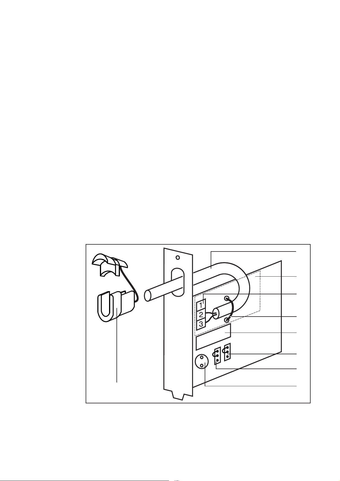
Übersicht
(9)
(1) Anschlusskabel (2- oder 3-polige Mantelleitung)
(2) Bauteilfreie Zone (Anschlusskabel so verlegen, dass es innerhalb
dieser Zone liegt)
(3) Klemme
(4) Kabelbinder
(1)
(2)
(3)
(4)
(5)
(6)
(7)
(8)
4
Übersicht
WARNUNG! Gefahr durch Netzspannung und DC-Spannung von
den Solarmodulen. Der Anschlussbereich darf nur durch lizenzierte Elektro-Installateure geöffnet werden. Der separate Bereich der
Leistungsteile darf nur durch Fronius geschultes Servicepersonal
im spannungsfreien Zustand geöffnet werden.
(Fortsetzung)
Installation
Sicherheit
(5) Relais
(6) Jumper Servicecode
(7) Jumper Summer
(8) Summer
(9) Zugentlastung für Anschlusskabel
DE
Fronius Signal
Card
Zu berücksichtigen
Spezifikation
Anschlusskabel
Beachten Sie für die Installation der Fronius Signal Card die Bedienungsanleitung des Wechselrichters, Abschnitt: „Steckkarten einsetzen“
Beim Einsetzen der Fronius Signal Card folgende Punkte berücksichtigen:
- Die Fronius Signal Cards nur an den Steckplätzen mit den Bezeichnungen „Option 1“, „Option 2“ oder „Option 3“ einstecken
- Keinesfall an einem mit ENS gekennzeichneten Steckplatz einsetzen
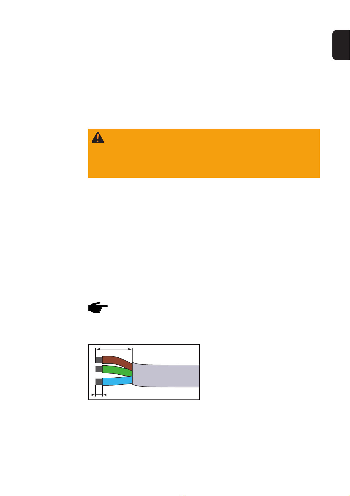
HINWEIS! Die Wirksamkeit der Zugentlastung ist nur bei einer
bestimmten Kabelstärke gewährleistet. Fronius empfiehlt die Verwendung einer 3-poligen 0,75 mm² Mantelleitung oder eines Kabels mit vergleichbarer Kabelstärke.
15 mm
Anschlusskabel wie folgt abisolieren:
- 15 mm der Mantelleitung abisolieren
- 5 mm der einzelnen Drähte
abisolieren
5 mm
5

Fronius Signal
Card installieren
Bei der Installation wie folgt vorgehen:
- AC und DC freischalten
- Anschlussbereich des Wechselrichter öffnen
HINWEIS! Beim Verlegen der Anschlusskabel darauf achten, dass
die Kabel keine elektronischen Bauteile oder Kanten berühren. Die
Kabel gemäß Abbildung in Form einer großräumigen Schleife
führen.
Zugentlastung unbedingt
verwenden!
Anschlusskabel innerhalb des eingezeichneten Bereiches verlegen!
1. Jumper nach Wunsch setzen (siehe Kapitel „Jumper“)
Nur bei Fronius IG:
Wichtig! Achten Sie bei der Auswahl des Steckplatzes darauf, dass sich
rechts von der Fronius Signal Card keine weiteren Steckkarten befinden,
damit Sie mit dem Schraubendreher komfortablen Zugriff auf die Klemme
haben. Sollte dies nicht möglich sein, führen Sie alle anderen Arbeitsschritte zuerst aus und stecken Sie die Fronius Signal Card erst nach
Arbeitsschritt 6 ein.
2. Nur bei Fronius IG: Abdeckblech an einem der Steckplätze entfernen
3. Fronius Signal Card einstecken und mittels Schraube fixieren
4. Anschlusskabel durch das Langloch am Anschlussblech der Fronius
Signal Card führen
5. Anschlusskabel an der Fronius Signal Card anklemmen (siehe Kapitel „Stromkreis anschließen“)
6. Anschlusskabel mittels mitgeliefertem Kabelbinder im Klemmbereich
fixieren
7. Zugentlastung ansetzen und in die Öffnung drücken
8. Anschlussbereich schließen
6
Stromkreis anschließen
DE
Merkmale
eines anzuschließenden
Stromkreises
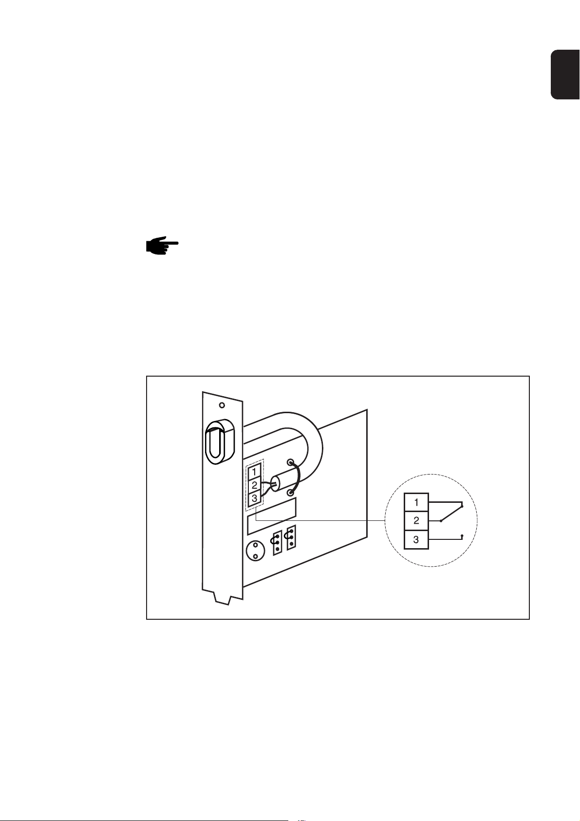
3-polige Klemme
Die Fronius Signal Card dient dem Anschließen eines Stromkreises. Der
Stromkreis kann z.B. eine Signaleinrichtung enthalten und muss folgenden Merkmalen entsprechen:
- Maximale DC-Spannung .................. 50 V DC
- Maximaler DC-Strom........................ 1 A DC
- Maximale AC-Spannung ................... 250 V AC
- Maximaler AC-Strom ........................ 4 A AC
- Maximaler Leitungsquerschnitt.........Bis zu 1,5 mm² / Leitung
HINWEIS! Die Wirksamkeit der Zugentlastung ist nur bei einer
bestimmten Kabelstärke gewährleistet. Fronius empfiehlt die Verwendung einer 3-poligen 0,75 mm² Mantelleitung oder eines Kabels mit vergleichbarer Kabelstärke.
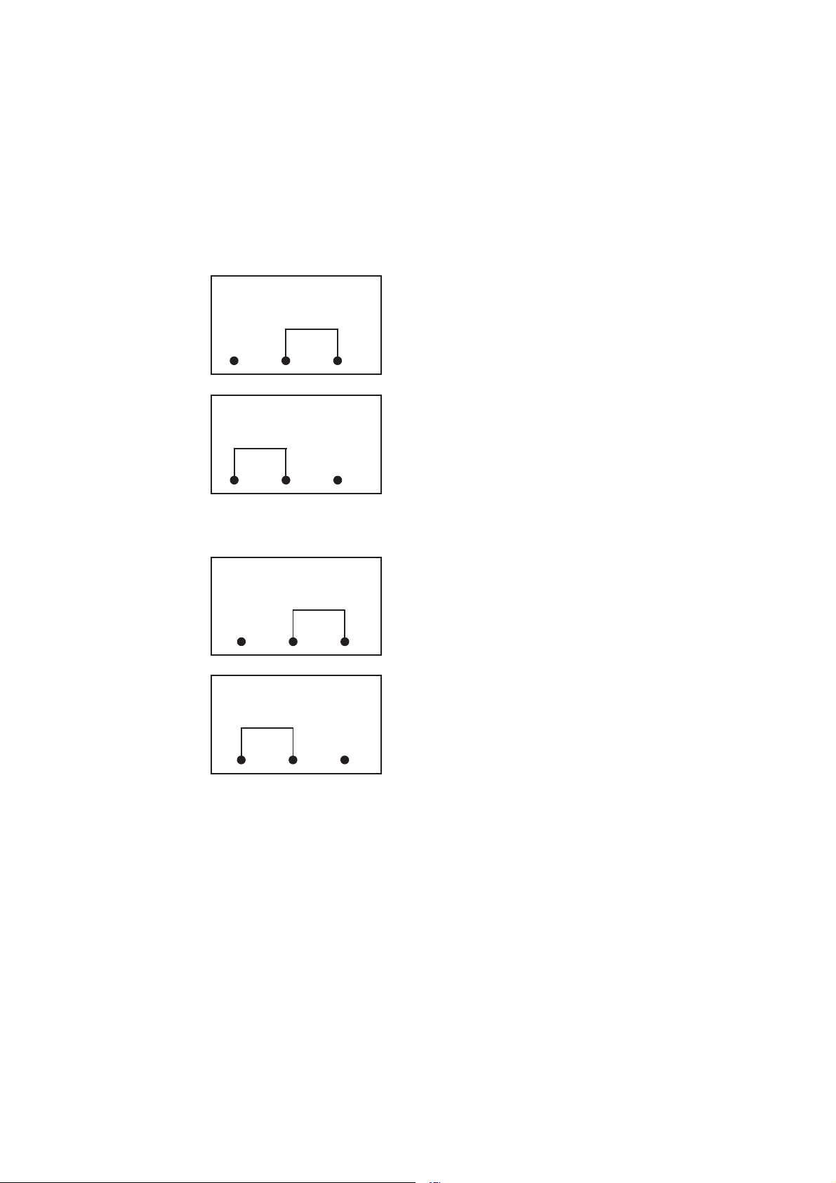
Die Ruhestellung des Relais ist direkt auf der Leiterplatte skizziert und
sieht wie folgt aus:
7
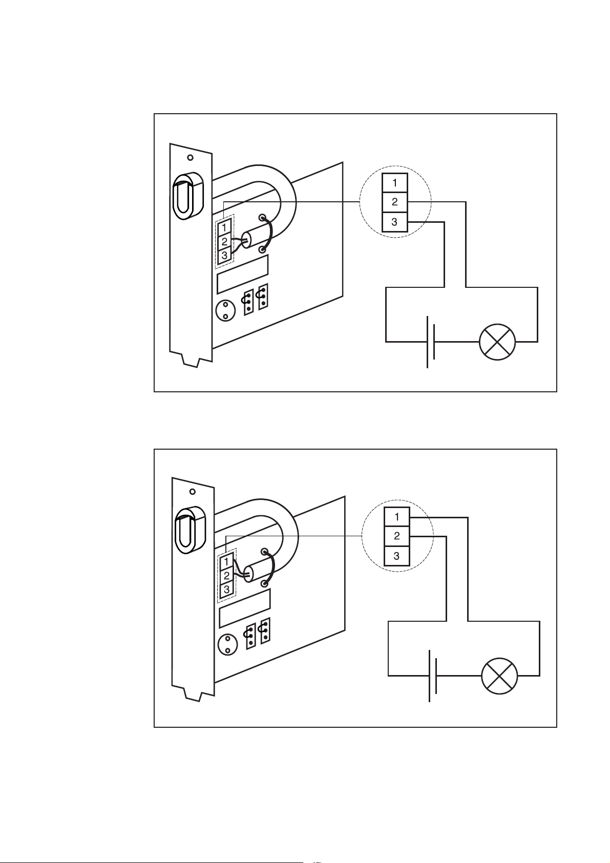
Relais als
Öffner und als
Schließer
Ein Beschalten des Relais ist wie folgt möglich:
- Als Schließer
- Als Öffner
8
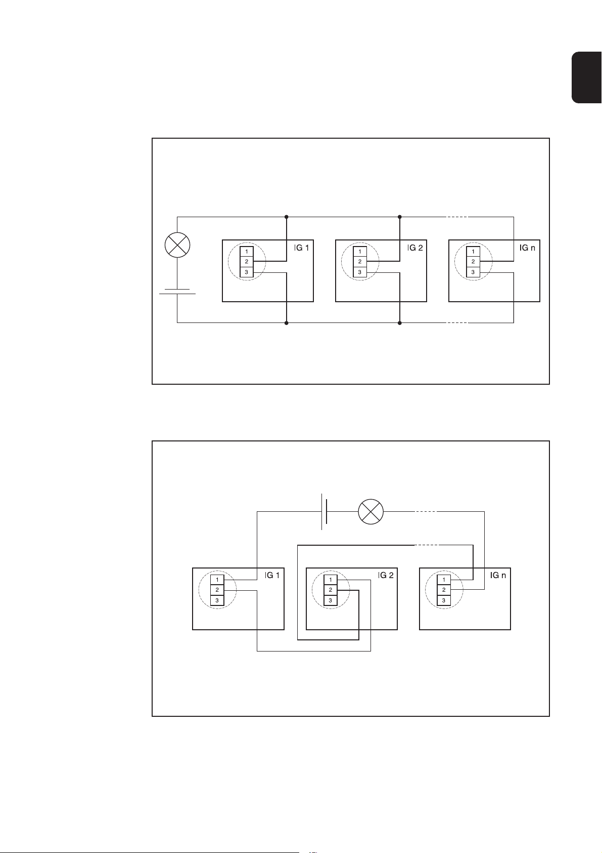
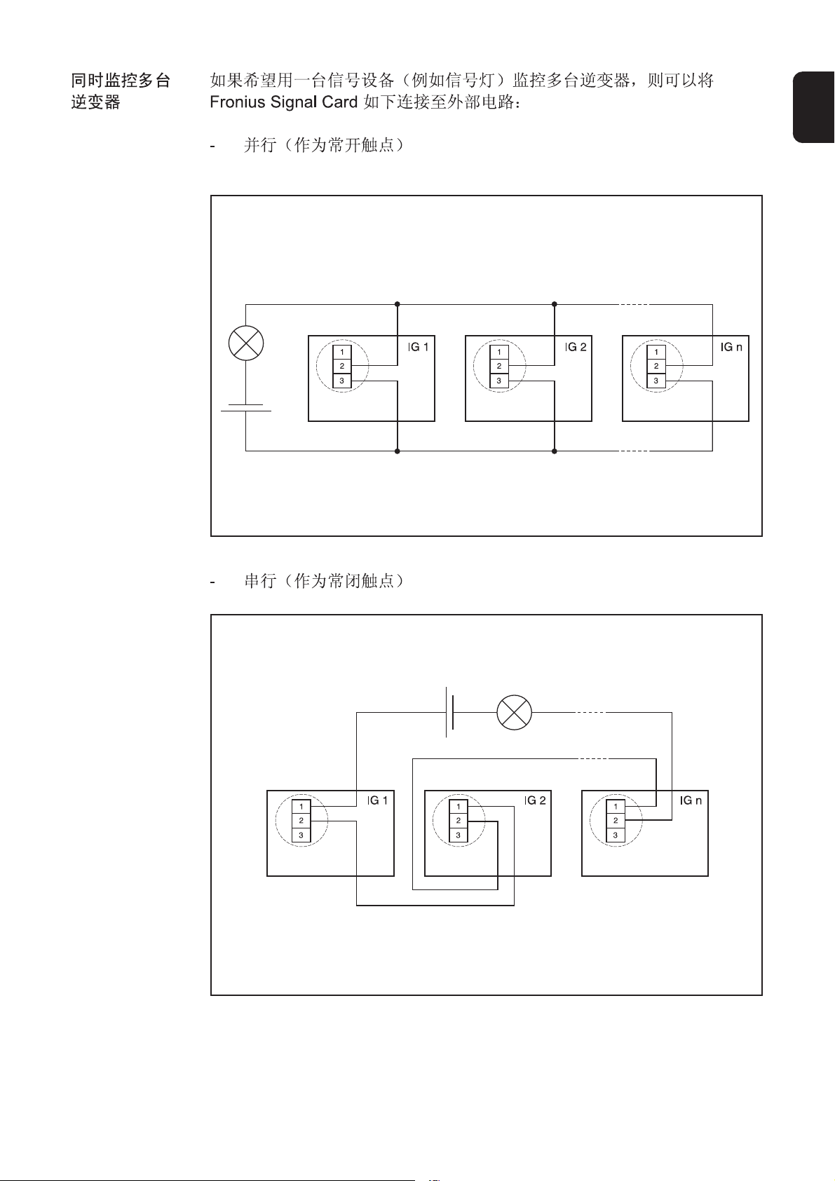
Gleichzeitiges
Überwachen
mehrerer
Wechselrichter
Sollten Sie mehrere Wechselrichter mit nur einer Signaleinrichtung (z.B.
Lampe) überwachen wollen, können Sie die Fronius Signal Card wie folgt
an den externen Stromkreis anschließen:
- Parallel (als Schließer)
DE
- In Serie (als Öffner)
9
Jumper
Allgemeines
1. Jumper
„Buz.“
2. Jumper
„Err.“
Folgende Jumper sind für persönliche Einstellungen verfügbar:
1. „Buz.“ (on/off) ... Standardeinstellung: „on“
2. „Err.“ (perm./all) ... Standardeinstellung „all“
Buz.
off on
Buz.
off
Err.
perm. all
on
- Stellung „on“ ... Wird ein Service-Code
angezeigt, ertönt ein Summer (akustisches
Signal). Die Abgabe des akustischen Signales erfolgt zusätzlich zum Schalten des
Relais.
- Stellung „off“ ... Wird ein Service-Code
angezeigt, schaltet nur das Relais. Die
zusätzliche Abgabe eines akustischen
Signales erfolgt nicht.
- Stellung „all“ ... Hier führen alle ServiceCodes (dauerhafte und temporäre) zu einem Schalten des Relais oder zu einem
Ertönen des Summers.
Err.
perm. all
A. Temporäre Service-Codes:
- Diese Service-Codes treten nur kurzfristig auf und verhindern für
kurze Zeit die Einspeisung.
Beispiel: Abschaltung auf Grund von Netzschwankungen
- Die Fronius Signal Card reagiert, sollte ein temporärer Service-Code
öfter als 50 Mal pro Tag auftreten.
B. Dauerhafte Service-Codes:
- Service-Codes, die zumeist einen Defekt des Wechselrichters betreffen und zu einem Stillstand des Wechselrichters führen (z.B. Hardware-Defekt).
- Die Fronius Signal Card reagiert, sollte ein dauerhafter Service-Code
länger als 4:15 Stunden angezeigt werden.
- Stellung „perm.“ ...Hier führen nur dauerhafte Service-Codes zu einem Schalten des
Relais oder zu einem Ertönen des Summers.
10

Stromversorgung
DE
DC-Versorgung
Relais als
potentialfreier
Kontakt
Die Anspeisung der Fronius Signal Card erfolgt über die DC-Versorgung
des Wechselrichters. An den Klemmen des Relais angeschlossene Verbraucher (z.B. Signaleinrichtungen) werden jedoch nicht mitversorgt.
Das Relais ist von der Versorgung der Fronius Signal Card und der Elektronik galvanisch getrennt (potentialfreier Kontakt). Eine eigenständige
Versorgung der angeschlossenen Verbraucher ist daher erforderlich.
Versorgung
Betrieb
Allgemeines
Besonderheiten
Wird ein Service-Code angezeigt, reagiert die Fronius Signal Card gemäß
Beschreibung der dauerhaften und temporären Service-Codes. Das Relais schließt, und bei entsprechender Jumper-Einstellung ertönt der Summer. Das Relais bleibt solange geschlossen, bis
- Am Wechselrichter eine Taste gedrückt wird
- Oder ein Trennen und erneutes Zuschalten der DC-Versorgung erfolgt
Wichtig! Erst eine erneutes Zuschalten der DC-Versorgung setzt das
Relais in die Ausgangsposition zurück.
Es kann daher vorkommen, dass das Relais auch nach Verlust der DCSpannung (Abends) geschaltet bleibt. Daher empfehlen wir den Einbau
eines EIN/AUS Schalters.
11

Besonderheiten
(Fortsetzung)
EIN/AUS Schalter
- Der Summer ertönt nur solange, wie der Wechselrichter von den
Solarmodulen versorgt wird.
- Das Relais bleibt in geschalteter Stellung, auch wenn die DC-Versorgung aufgrund von Dunkelheit nicht mehr gegeben ist.
- Das Quittieren des Service-Codes und damit ein Rücksetzen des
Relais ist nur bei vorhandener DC-Versorgung möglich.
- Ein kurzes Ertönen des Summers beim Hochstarten des Wechselrichters ist Teil der Initialisierungsroutine und deutet auf keine Fehlfunktion hin.
Anwendungsmöglichkeiten
Der Einsatz einer Fronius Signal Card ist für Wechselrichter ab Seriennummer 14330071 möglich.
Bei älteren Wechselrichtern ist ein Hardware-Update erforderlich. Wenden
Sie sich bitte diesbezüglich an Ihren Installateur.
Technische Daten
Fronius Signal Card
Versorgungsspannung: 5 V DC (erfolgt durch Solarmodule)
Abmessungen (l x b x h): 140 x 100 x 26 mm
Maximale Schalteigenschaften des Relais
- U(DC): 50 V
- I(DC): 1 A
- U(AC): 250 V
- I(AC): 4 A
Maximaler Leitungsquerschnitt: 1,5 mm² / Leitung
Empfohlenes Anschlusskabel: 3-polige 0,75 mm² Mantelleitung

Dear reader,
WARNING! Work that is carried out incorrectly can cause serious
injury or damage. Installation and commissioning of the the Fronius Signal Card may only be carried out in accordance with the
technical regulations. It is essential that you read the „Safety
regulations“ chapter before commissioning the equipment or
carrying out maintenance work.
„WARNING!“ Indicates a potentially dangerous situation. Death
or serious injury may result if appropriate precautions are not
taken.
The operating
instructions
and your safety
Safety
These operating instructions will help you familiarise yourself with the
installation, operation, care and maintenance of the Fronius Signal Card.
It is in your interests to read these operating instructions carefully and to
observe the directions contained herein. This will help prevent any damage caused by incorrect operation. The device will reward you for your
trouble by remaining in constant working order throughout its long service
life.
EN
Explanation of safety instructions
WARNING!
CAUTION!
Note!
Important!
„CAUTION!“ Indicates a situation where damage or injury could
occur. Minor injury and/or damage to property may result if appropriate precautions are not taken.
„NOTE!“ Indicates a risk of flawed results and possible damage to
the equipment.
„Important!“ highlights tips for correct operation and other particularly
useful information. It does not denote a potentially damaging or dangerous situation.
If you see any of the symbols depicted in the „Safety rules“ chapter, special care is required.
1

Protection of personnel
Housing
Galvanic (electrical) isolation
The inverter connection compartment must only be opened by an authorised installation engineer.
Never open the connection compartment when the power is connected.
The separate power module housing must only be opened by a trained
Fronius service technician and only when in a de-energised state.
The design and operation of the inverter ensures maximum safety when
installing the Fronius Signal Card. The DC and AC sides are fully galvanically (electrically) isolated from one another to ensure optimum levels of
safety.
To provide maximum safety during operation, the connections of the Fronius Signal Card are also fully galvanically (electrically) isolated.
Never route leads connected to the Fronius Signal Card together with
mains leads.
Repairs
Repairs to the inverter and the Fronius Signal Card may only be carried
out by a trained Fronius service technician.
2

Contents
Dear reader ....................................................................................................................... 1
The operating instructions and your safety ................................................................... 1
Safety ............................................................................................................................ 1
Explanation of safety instructions ...................................................................................... 1
Protection of personnel ..................................................................................................... 2
Housing .........................................................................................................................2
Galvanic (electrical) isolation ........................................................................................ 2
Repairs.......................................................................................................................... 2
General ............................................................................................................................. 4
Fronius Signal Card ...................................................................................................... 4
Overview ....................................................................................................................... 4
Installation ......................................................................................................................... 5
Safety ............................................................................................................................ 5
Fronius Signal Card ...................................................................................................... 5
Please note ................................................................................................................... 5
Connection cable specification...................................................................................... 5
Installing the Fronius Signal Card ................................................................................. 6
EN
Connecting the circuit ........................................................................................................ 7
Features of a compatible circuit .................................................................................... 7
3-pin terminal ................................................................................................................ 7
Relay as an NC and NO contact ................................................................................... 8
Simultaneous monitoring of several inverters ............................................................... 9
Jumper ............................................................................................................................ 10
General ....................................................................................................................... 10
1. „Buz.“ jumper .......................................................................................................... 10
2. „Err.“ jumper ............................................................................................................ 10
Power supply....................................................................................................................11
DC supply ....................................................................................................................11
Relay as a floating contact ........................................................................................... 11
Operation .........................................................................................................................11
General ........................................................................................................................11
Special features ........................................................................................................... 11
Applications ..................................................................................................................... 12
Technical data ................................................................................................................. 12
3

General
Fronius Signal
Card
Overview
The Fronius Signal Card keeps you up-to-date with the operating status of
your inverter in real time. It may be used with the following inverters:
- Fronius IG
- Fronius IG Plus
- Fronius IG Plus V
Note the following special features of the Fronius Signal Card:
- The Fronius Signal Card is not a Fronius Solar Net component and
therefore does not require a Datalogger
- The Fronius Signal Card is only available as a card and can only ever
monitor one inverter at a time
- The Fronius Signal Card detects serious inverter malfunctions
- If a malfunction is detected, the Fronius Signal Card trips a relay and
also emits an acoustic signal (see „Jumper“ chapter)
- The relay activates a consumer chosen by the user (e.g. a visual or
acoustic alarm)
(1)
(2)
(3)
(4)
(5)
(6)
(7)
(9)
(1) Connection cable (2-pin or 3-pin sheathed cable)
(2) Component-free zone (route the connection cable so that it lies within
this zone)
(3) Terminal
(4) Cable tie
(5) Relay
(6) Service code jumper
(7) Buzzer jumper
(8) Buzzer
(9) Strain-relief device for connection cable
(8)
4

Installation
WARNING! Danger due to grid voltage and DC voltage from solar
modules. The connection compartment should only ever be
opened by an authorised electrical engineer. The separate housing containing the power modules must only be opened by a
Fronius-trained service technician and only when in a de-energised state.
Safety
EN
Fronius Signal
Card
Please note
Connection
cable specification
To install the Fronius Signal Card, please see the following section in the
inverter operating instructions: „Installing plug-in cards“
The following points should be borne in mind when installing the Fronius
Signal Card:
- Only install Fronius Signal Cards in the slots marked „Option 1“,
„Option 2“ or „Option 3“
- Never insert a Fronius Signal Card into a slot marked ENS
NOTE! The effectiveness of the strain-relief device is only guaranteed for cables of a certain thickness. Fronius recommends a 3-pin
0.75 mm² sheathed cable or a cable of equivalent thickness.
15 mm
5 mm
Strip the connection cable insulation as follows:
- Strip 15 mm of the sheathed
cable insulation
- Strip 5 mm of insulation off the
individual wires
5

Installing the
Fronius Signal
Card
To install, proceed as follows:
- Disconnect AC and DC
- Open the inverter connection area
NOTE! When routing the connection cable, ensure that it does not
come into contact with any electronic parts or edges. Lay the cable
as a large loop as shown in the diagram.
Strain-relief device must
be used at all times.
Route the connection cable within
the marked area.
1. Set the jumper as desired (see „Jumper“ chapter)
Fronius IG Plus only:
Important! To allow sufficient screwdriver access to the terminal, ensure
that there are no plug-in cards to the right of the slot earmarked for the
Fronius Signal Card. Should this not be possible, complete all other steps
first and only plug the Fronius Signal Card in after completing step 6.
2. Fronius IG Plus only: Remove the cover plate from one of the slots
3. Insert the Fronius Signal Card and secure with a screw
4. Guide the connection cable through the hole in the Fronius Signal
Card connection plate
5. Connect the connection cable to the Fronius Signal Card (see „Connecting the circuit“)
6. Secure the connection cable in the clamping area using the cable tie
supplied
7. Fit the strain-relief device and press into the opening
8. Close connection compartment
6

Connecting the circuit
Features of a
compatible
circuit
3-pin terminal
The Fronius Signal Card forms the connection to a circuit. The circuit may
include elements such as a signalling device and must comply with the
following:
- Maximum DC voltage ....................... 50 V DC
- Maximum DC current ....................... 1 A DC
- Maximum AC voltage .......................250 V DC
- Maximum AC current ........................4 A DC
- Maximum cable cross-section .......... Up to 1.5 mm² / cable
NOTE! The effectiveness of the strain-relief device is only guaranteed for cables of a certain thickness. Fronius recommends a 3-pin
0.75 mm² sheathed cable or a cable of equivalent thickness.
The relay off-position is marked directly on the PC board and appears as
follows:
EN
7

NC and NO
contact
The relay may be wired as follows:Relay as an
- As an NO contact
- As an NC contact
8

Simultaneous
monitoring of
several inverters
If you wish to monitor several inverters with just a single signalling device
(e.g. light), connect the Fronius Signal Card to the external circuit as
follows:
- Parallel (as an NO contact)
EN
- In series (as an NC contact)
9

Jumper
General
1. „Buz.“ jumper
2. „Err.“ jumper
The following jumpers are available for individual settings:
1. „Buz.“ (on/off) ... Default setting: „on“
2. „Err.“ (perm./all) ... Default setting: „all“
Buz.
off on
Buz.
off
Err.
perm. all
on
- „on“ position ... A buzzer (acoustic signal)
sounds if a service code is signalled. Sounding the acoustic signal also switches the
relay.
- „off“ position ... Only the relay is switched if
a service code is signalled. An additional
acoustic signal is not emitted.
- „all“ position ... Every service code (permanent or temporary) causes the relay to
switch or the buzzer to sound.
Err.
perm. all
A. Temporary service codes:
These service codes only appear temporarily and prevent feeding
into the grid for a short time.
Example: Deactivation due to fluctuations in the mains voltage
- The Fronius Signal Card reacts if a temporary service code occurs
more than 50 times in a single day.
B. Permanent service codes:
- Service codes that concern at least one fault in the inverter and cause it to stop (e.g. hardware fault).
- The Fronius Signal Card reacts if a permanent service code is signalled for longer than 4:15 hours.
- „perm“ position ...Only permanent service
codes cause the relay to switch or the buzzer to sound.
10

Power supply
DC supply
Relay as a
floating contact
Power is supplied to the Fronius Signal Card via the inverter DC supply.
However, any consumers (e.g. signalling devices) connected to the relay
terminals are not powered from this source.
The relay is galvanically (electrically) isolated (floating contact) from the
Fronius Signal Card supply and the electronics. An independent power
supply for the consumers is therefore necessary.
Power supply
EN
Operation
General
Special features
If a service code is signalled, the Fronius Signal Card will respond in the
manner described for permanent and temporary service codes. The relay
closes and, depending on the jumper setting, the buzzer may also sound.
The relay remains closed until:
- a button is pressed on the inverter
- or the DC supply is switched off and back on again
Important! Only switching the DC supply back on will return the relay to
its original position.
As a result it is possible that the relay will remain switched even after the
DC voltage is lost (evenings). We therefore recommend fitting an ON/OFF
switch.
11

Special features
(continued)
ON/OFF switch
- The buzzer only sounds while the inverter is being supplied with
power from the solar modules.
- The relay remains in its switched position, even when the DC supply
is terminated due to the onset of darkness.
- A service code can only be acknowledged (and the relay reset) when
the DC supply is available.
- The buzzer sounds briefly while the inverter is starting up - this is a
standard part of the initialisation routine and does not indicate a malfunction.
Applications
Fronius Signal Cards may be used with inverters from serial number
14330071.
A hardware update is required for older inverters. Please contact your
installation engineer for further information.
Technical data
Fronius Signal Card
Supply voltage: 5 V DC (through solar modules)
Dimensions (l x w x h): 140 x 100 x 26 mm
Maximum relay switching characteristics
- U(DC): 50 V
- I(DC): 1 A
- U(AC): 250 V
- I(AC): 4 A
Maximum cable cross-section: 1.5 mm² / cable
Recommended connection cable: 3-pin 0.75 mm² sheathed cable
12

ZH
1

2

ZH
3

(1)
(2)
(3)
(4)
(5)
(6)
(7)
(9)
(8)
4

ZH
5 mm
15 mm
5

6

ZH
7

8
ZH
9

Buz.
off on
Buz.
off
on
Err.
perm. all
Err.
perm. all
10

ZH
11


Fronius Worldwide - www.fronius.com/addresses
Fronius International GmbH
4600 Wels, Froniusplatz 1, Austria
E-Mail: pv@fronius.com
http://www.fronius.com
Under http://www.fronius.com/addresses you will find all addresses of our sales branches and partner firms!
Fronius USA LLC Solar Electronics Division
USAA
10421 Citation Drive, Suite 1100, Brighton, MI 48116
E-Mail: pv-us@fronius.com
http://www.fronius-usa.com
ud_fr_se_so_00913 012011
 Loading...