

Operating
Instructions
Selectiva Li 3 kW
2120 / 4060
Operating Instructions
EN
42,0426,0309,EN 011-01122022


Contents
Safety rules 4
General 4
Intended use 4
Environmental conditions 4
Mains connection 5
Dangers from mains current and charging current 5
Dangers posed by the battery 5
General information regarding the handling of lithium batteries 6
Protecting yourself and others 7
Safety measures in normal operation 7
EMC Device Classifications 7
EMC measures 7
Data protection 7
Maintenance 8
Obligations of the operator 8
Safety inspection 8
Markings on the device 8
Disposal 9
Copyright 9
General information 10
Explanation of safety notices 10
Device concept 10
Customer-specific information 10
Correct battery configuration 10
Mains connection 11
Correct installation of the mains/charging cables 11
Warning notices on the device 12
Warning notices inside the device 13
Setup regulations 13
Wall and floor bracket 15
Control elements and connections 17
Controls and connections 17
Control panel 19
Charging the battery 21
Charging 21
Interrupting charging 23
Stopping charging 24
Display 25
Overview of display modes 25
Standard mode 25
Menu selection 26
Statistics mode 26
History mode 27
Configuration mode 28
Charging settings 30
Additional functions 34
General settings 37
Reset settings 39
USB mode 39
Status codes 41
Options 45
Safety 45
LED strip 45
Air filter 45
"Mobile" kit 46
Wall bracket 46
Floor bracket 46
Mounting plate 46
Technical data 47
Selectiva 3 kW Li-Ion 47
EN
3

Safety rules
General The device has been manufactured in line with the state of the art and according
to recognized safety standards. If used incorrectly or misused, however, it can
cause:
Serious or fatal injury to the operator or third parties
-
Damage to the device and other material assets belonging to the operating
-
company
Inefficient operation of the device
-
All persons involved in commissioning, operating, maintaining and servicing the
device must:
Be suitably qualified
-
Read and follow these Operating Instructions carefully
-
The Operating Instructions must always be at hand wherever the device is being
used. In addition to the Operating Instructions, attention must also be paid to
any generally applicable and local regulations regarding accident prevention and
environmental protection.
All safety and danger notices on the device:
Must be kept in a legible state
-
Must not be damaged/marked
-
Must not be removed
-
Must not be covered, pasted, or painted over
-
For the location of the safety and danger notices on the device, refer to the section headed "General information" in the Operating Instructions for your device.
Before switching on the device, rectify any faults that could compromise safety.
This is for your personal safety!
Intended use The device is to be used exclusively for its intended purpose. Any use above and
beyond this purpose is deemed improper. The manufacturer is not liable for any
damage, or unexpected or incorrect results arising out of such misuse.
Proper use also includes:
Carefully reading and following all Operating Instructions, safety and danger
-
notices
Performing all stipulated inspection and servicing work
-
Following all instructions from the battery and vehicle manufacturers
-
Proper handling of the device is essential for it to function correctly. Never pull
on the cable when handling the device.
Environmental
conditions
Operation or storage of the device outside the stipulated area will be deemed as
not in accordance with the intended purpose. The manufacturer shall not be held
liable for any damage arising from such usage.
For exact information on permitted environmental conditions, please refer to the
"Technical data" section.
4

Mains connection
Devices with a higher rating may affect the energy quality of the mains due to
their current consumption.
This may affect a number device types in terms of:
Connection restrictions
-
-
Criteria with regard to the maximum permissible mains impedance
-
Criteria with regard to the minimum short-circuit power requirement
*)
at the interface with the public grid
*)
*)
see "Technical data"
In this case, the plant operator or the person using the device should check
whether the device may be connected, where appropriate by discussing the matter with the power supply company.
IMPORTANT! Ensure that the mains connection is earthed properly
EN
Dangers from
mains current
and charging
current
Dangers posed
by the battery
Anyone working with battery chargers exposes themselves to numerous dangers,
e.g.:
Risk of electrocution from mains current and charging current.
-
Hazardous electromagnetic fields, which can risk the lives of those using car-
-
diac pacemakers.
An electric shock can be fatal. Every electric shock is potentially life threatening.
To avoid electric shocks while using the charger:
Do not touch any live parts inside or on the outside of the charger.
-
Under no circumstances touch the battery poles.
-
Do not short-circuit the charging cable or charging terminals.
-
All cables and leads must be secured, undamaged, insulated and adequately dimensioned. Loose connections, scorched, damaged or inadequately dimensioned
cables and leads must be immediately repaired by authorised personnel.
The substances contained in the battery to be charged can be harmful to the environment as well as to human and animal health.
If the battery becomes damaged, please observe the following points:
Make sure that leaking fluids cannot get into the soil or groundwater
-
If pollution has already occurred, it must be removed in accordance with rel-
-
evant national regulations
The battery can catch fire if overheated. Do not expose the battery to heat
(e.g. a permanent heat source or fire).
If the battery is damaged or subjected to improper use, dangerous vapours may
be given off, which can irritate the airways.
If this happens:
Ensure an adequate supply of fresh air
-
Seek medical attention in case of discomfort
-
Liquid may emerge from a faulty battery.
Avoid contact with the liquid
-
Take the battery to an authorised service centre for repair
-
Clean and check any parts that have come into contact with the liquid
-
Do not operate or store the device in a potentially explosive atmosphere.
Special regulations apply in rooms at risk of fire or explosion.
Observe relevant national and international regulations.
5

To comply with European Directive 2006/66/EC on batteries and its implementation in national law, batteries that have reached the end of their life must be collected separately and returned to an approved recycling facility. Be sure to return any used battery to your dealer, or find out about the approved collection
and recycling facilities in your area. Ignoring this European Directive may be
harmful to the environment and your own health!
As soon as it appears that the battery has been mechanically damaged, dispose
of the battery in accordance with national laws and guidelines at your nearest recycling centre.
If anything is unclear or for any questions concerning disposal, contact an authorised service centre.
General information regarding
the handling of
lithium batteries
Lithium batteries have a gas-tight seal and are harmless provided the manu-
-
facturer's specifications are adhered to during use and handling
Never use chargers that are not suitable for the battery type
-
Do not short-circuit
-
Do not mechanically damage them (tap, deform, dismantle, etc.)
-
Never heat them to above the permissible temperature or burn them
-
Always store batteries in a cool, dry place
-
Lithium batteries are safe to use if they are handled properly within the para-
-
meters specified by the manufacturer
Mishandling or circumstances that result in improper use can result in the
-
battery contents and decomposition products leaking and related reactions
that are extremely hazardous to health and the environment
As a wide variety of chemical substances are found inside the battery, in the
-
event of an accident always follow the manufacturer's specifications regarding emergency response actions and first aid
Lithium batteries must, in all circumstances, be handled according to the
-
manufacturer's instructions
In particular, this applies to observing the limits for maximum current load,
-
charging and cutoff voltages as well as mechanical and thermal loads
The charger and battery are designed to work together and must not be
-
modified or manipulated in any way as this can result in considerable safety
risks
Ideally, lithium batteries should be stored at room temperature in a dry loca-
-
tion (details regarding the storage temperature range can be found in the
manufacturer's instructions)
Large temperature fluctuations must be avoided (e.g. do not store the batter-
-
ies near to heaters, do not expose them to prolonged sunlight)
Should damage or improper handling result in the leakage of substances,
-
then the manufacturer's instructions must be followed
This includes the use of personal protective equipment
-
When storing large quantities of lithium batteries, the local authorities
-
should be consulted
Employees must be trained on how to correctly handle lithium batteries (in
-
the same way as hazardous substances)
6

Protecting yourself and others
While the charger is in operation, keep all persons, especially children, out of the
working area. If, however, there are people in the vicinity,
warn them about all the dangers (hazardous electrolytes and gases, danger
-
from mains and charging current, etc.),
provide suitable protective equipment.
-
Before leaving the work area, ensure that people or property cannot come to any
harm in your absence.
EN
Safety measures
in normal operation
EMC Device
Classifications
Chargers with a ground conductor must only be operated on a mains supply with
a ground conductor and a socket with a ground conductor contact. If the charger
is operated on a mains supply without a ground conductor or in a socket without
a ground conductor contact, this will be deemed gross negligence. The manufacturer shall not be held liable for any damage arising from such usage.
Only operate the charger in accordance with the degree of protection shown on
the rating plate.
Under no circumstances operate the charger if there is any evidence of damage.
Arrange for the mains cable to be checked regularly by a qualified electrician to
ensure the ground conductor is functioning properly.
Any safety devices and parts that are not functioning properly or are in imperfect
condition must be repaired by a qualified technician before switching on the
charger.
Never bypass or disable protection devices.
After installation, an accessible mains plug is required.
Devices in emission class A:
Are only designed for use in industrial settings
-
Can cause line-bound and radiated interference in other areas
-
Devices in emission class B:
Satisfy the emissions criteria for residential and industrial areas. This is also
-
true for residential areas in which the energy is supplied from the public lowvoltage mains.
EMC device classification as per the rating plate or technical data.
EMC measures In certain cases, even though a device complies with the standard limit values for
emissions, it may affect the application area for which it was designed (e.g. when
there is sensitive equipment at the same location, or if the site where the device
is installed is close to either radio or television receivers).
If this is the case, then the operating company is obliged to take appropriate action to rectify the situation.
Data protection The user is responsible for the safekeeping of any changes made to the factory
settings. The manufacturer accepts no liability for any deleted personal settings.
7

Maintenance Before switching on, always check the mains plug and cable as well as charger
leads and charging terminals for any signs of damage.
If the surface of the device housing is dirty, clean with a soft cloth and solventfree cleaning agent only.
Obligations of
the operator
Safety inspection
The operator must only allow persons to work with the device who:
are familiar with the fundamental instructions regarding safety at work and
-
accident prevention and have been instructed in how to use the device
have read and understood these operating instructions, especially the sec-
-
tion "safety rules", and have confirmed as much with their signatures
are trained to produce the required results.
-
Checks must be carried out at regular intervals to ensure that operators are
working in a safety-conscious manner.
The manufacturer recommends that a safety inspection of the device is performed at least once every 12 months.
The safety inspection may only be performed by an appropriately qualified electrician
After any changes have been made
-
After any additional parts are installed, or after any conversions
-
After repair, care and maintenance are carried out
-
At least every twelve months
-
For safety inspections, follow the appropriate national and international standards and directives.
Further details on safety inspections can be obtained from your service centre.
They will provide you on request with any documents you may require.
Markings on the
device
Devices with the CE marking satisfy the essential requirements of the applicable
guidelines.
Devices displaying the EAC mark of conformity satisfy the requirements of the
relevant standards in Russia, Belarus, Kazakhstan, Armenia and Kyrgyzstan.
8

Disposal Waste electrical and electronic equipment must be collected separately and re-
cycled in an environmentally-friendly way, in accordance with the European Directive and national legislation. Used equipment must be returned to the distributor or disposed of via an approved local collection and disposal facility. Correct
disposal of used equipment promotes the sustainable recycling of material resources. Failing to dispose of used equipment correctly can lead to adverse
health and/or environmental impacts.
Packaging materials
Separate collection according to material. Check your local authority regulations.
Crush containers to reduce size.
Copyright Copyright of these operating instructions remains with the manufacturer.
The text and illustrations are all technically correct at the time of printing. We
reserve the right to make changes. The contents of the operating instructions
shall not provide the basis for any claims whatsoever on the part of the purchaser. If you have any suggestions for improvement, or can point out any mistakes that you have found in the instructions, we will be most grateful for your
comments.
EN
9
General information
Explanation of
safety notices
DANGER!
Indicates immediate danger.
If not avoided, death or serious injury will result.
▶
WARNING!
Indicates a potentially hazardous situation.
If not avoided, death or serious injury may result.
▶
CAUTION!
Indicates a situation where damage or injury could occur.
If not avoided, minor injury and/or damage to property may result.
▶
NOTE!
Indicates a risk of flawed results and possible damage to the equipment.
Device concept The technology is embedded in a robust industry-standard housing. The excep-
tionally compact design complies with all safety standards, requires less installation space and protects the components to ensure a long service life.
Fitted with a graphical display, an integrated datalogger, new interfaces and additional options, the device is perfectly equipped for the future.
Customer-specific information
Correct battery
configuration
If customer-specific information is available for the supplied device, supply them
with the device.
WARNING!
Danger due to unsuitable batteries being connected to the charger.
Escaping gas, fire or explosion may result in serious injury and damage to property.
Never connect a battery to the charger unless it is compatible in terms of its
▶
type and voltage and the charger settings are correct.
The charger must only be used with lithium-ion batteries approved by Froni-
▶
us.
10
WARNING!
Mains connection
Danger due to trailing charging leads.
This could result in injury due to getting caught or tripping on loose cables.
Lay the charging leads so that no one can trip over or become entangled in
▶
them.
WARNING!
Danger due to charging plug being pulled out during charging.
This may result in serious injury and damage to property.
Before pulling out the charging plug, first stop the charging process using
▶
the Stop/Start key.
Once the charging process is complete, wind up the charging lead or, if avail-
▶
able, place it on the cable holder.
WARNING!
Danger from incorrect operation.
This can result in severe personal injury and damage to property.
Do not use the functions described here until you have fully read and under-
▶
stood the following documents:
All the Operating Instructions for the system components, especially the
▶
safety rules
Battery and vehicle manufacturer's Operating Instructions and safety rules
▶
EN
Correct installation of the
mains/charging
cables
WARNING!
Danger due to faulty or insufficient power supply.
This can result in severe personal injury and damage to property.
The power supply requirements detailed in "Technical data" must be met.
▶
CAUTION!
Danger due to overheating caused by laying the mains/charging cables incorrectly.
Risk of damage to the components.
Lay mains/charging cable without loops.
▶
Do not cover mains/charging cable.
▶
Charging cables longer than 5 m (16 ft. 4.85 in.) Lay cables individually (no
▶
bundling).
Charging cables of more than 5 m (16 ft. 4.85 in.) Cables may have an in-
▶
creased surface temperature (caution: hot surfaces).
In the following cases, ensure in particular that the surface temperature of
▶
the charging cables does not exceed 80 °C (176 °F):
- Ambient temperature is 30 °C (86 °F) or more
- Cross-section of the charging cable is 95 mm2 or more
- Length of the charging cable is 5 m (16 ft. 4.85 in.) or more
The mains/charging cable may only be replaced by a qualified electrician.
▶
11

Warning notices
OVC III
UAC nom.
IAC max.
PAC max.
UDC nom.
IDC max.
Part No.:
Ser. No.:
Protective class I
Selectiva xxxx Li 3kW
4,010,xxx,876
xxxxxxxx
xxxxxxxx
XXXX
xxxx
IP21
1~ NPE 230V 50/60Hz
xxxA
xxV
xxxxW
xxA
EMC emission
Class A
Fronius International GmbH
Froniusstraße 1
A-4643 Pettenbach
Austria
Ladevorgang immer stoppen bevor das Ladekabel abgezogen wird!
Nur mit zugelassener Lithium Ionen Batterie verwenden!
Always stop charging before you disconnect the charging cable!
Use only with approved lithium ion battery!
Toujours arrêter la charge avant de déconnecter le câble de charge!
Utiliser uniquement avec des batteries lithium-ion agréées!
¡Detener siempre la carga antes de desconectar el cable de carga!
¡Utilizar exclusivamente baterías de iones de litio homologadas!
Interrompere sempre la carica prima di scollegare il cavo di carica!
Utilizzare solo con la batteria agli ioni di litio approvata!
Li
WARNUNG - WARNING - ATTENTION
ADVERTENCIA - AVVISO
42,0409,0420
on the device
12
A number of safety symbols can be seen on the charger's rating plate. The
safety symbols must not be removed or painted over.
An electric shock can be fatal. The housing must never be opened by
anyone other than a service technician trained by the manufacturer.
The device must be disconnected from the mains before starting any
work with the housing open. A suitable measuring instrument must be
used to ensure that electrically charged components (e.g. capacitors)
are fully discharged. Ensure that the device remains disconnected
from the mains until all work has been completed.
Do not use the functions until you have fully read the Operating Instructions.

Possible sources of ignition, such as fire, sparks and naked flames,
4,010,xxx,876
xxxxxxxx
XXXX
WARNING Hazardous Voltage
Kondensator Entladezeit < 2 min.
Capacitor discharge time < 2 min.
Décharge de condensateur < 2 min.
Condensador tiempo de descarga < 2 min.
Condensatore tempo di scaricamento < 2 min.
UDC nom. xxV
Part No.:
Ser. No.:
1
2
1 Display
2 Battery CR2032
----- (1)
----- (3)
CAN1 High (5)
CAN1 Low (7)
CAN1 GND (9)
Status 1 (11)
Status 3 (13)
(4) -----
(6) CAN2 High (green)
(8) CAN2 Low (yellow)
(10) +13V
(12) CAN2 GND (brown)
(14) Status 4
(2) -----
must be kept away from the battery.
Do not dispose of used chargers with domestic waste. Dispose of them
according to the safety rules.
EN
Warning notices
inside the device
WARNING!
Danger from electric current.
This can result in serious injury or death.
The housing must never be opened by anyone other than a trained service
▶
technician.
The device must be disconnected from the mains before starting any work
▶
with the housing open.
A suitable measuring instrument must be used to ensure that electrically
▶
charged components (e.g. capacitors) are fully discharged.
Use an easily legible and understandable warning sign to ensure that the
▶
device is not reconnected to the mains supply before all the work has been
completed.
Inside the device:
Setup regulations
WARNING!
Danger from machines falling or toppling over.
This may result in serious injury and damage to property.
Make sure that all system components are securely in position when setting
▶
them up.
If using a floor bracket or wall bracket, always make sure that all the fasten-
▶
ings are secure.
The device is tested to IP 21 protection, meaning:
Protection against penetration by solid foreign bodies with diameters ex-
-
ceeding 12.5 mm (0.49 in.)
Protection against vertically falling drops of water
-
The device can be set up and operated in dry, closed areas that comply with degree of protection IP21. Exposure to wet conditions should be avoided.
13

The device may only be operated in a
20 cm (7.87 in.)
horizontal position.
Cooling air
The charger must be set up in such a way that the cooling air can flow unimpeded through the vents in the housing that are provided for that purpose. Ensure that there is always a minimum clearance of 20 cm (7.87 in.) around the air
inlets and outlets. The surrounding air must be free from
Excessive dust
-
Electrically conductive particles (carbon black or swarf)
-
Heat sources
-
Cooling air is drawn in and flows out as indicated by the arrows in the following
illustrations.
NOTE!
Danger due to partially or fully covered air inlets and outlets.
This can result in damage to property.
If several chargers are set up one behind the other, they should be offset.
▶
If the chargers are arranged in a line one behind the other without being offset,
the space between the chargers must be as follows:
Minimum distance 20 cm (7.87 in)
-
14
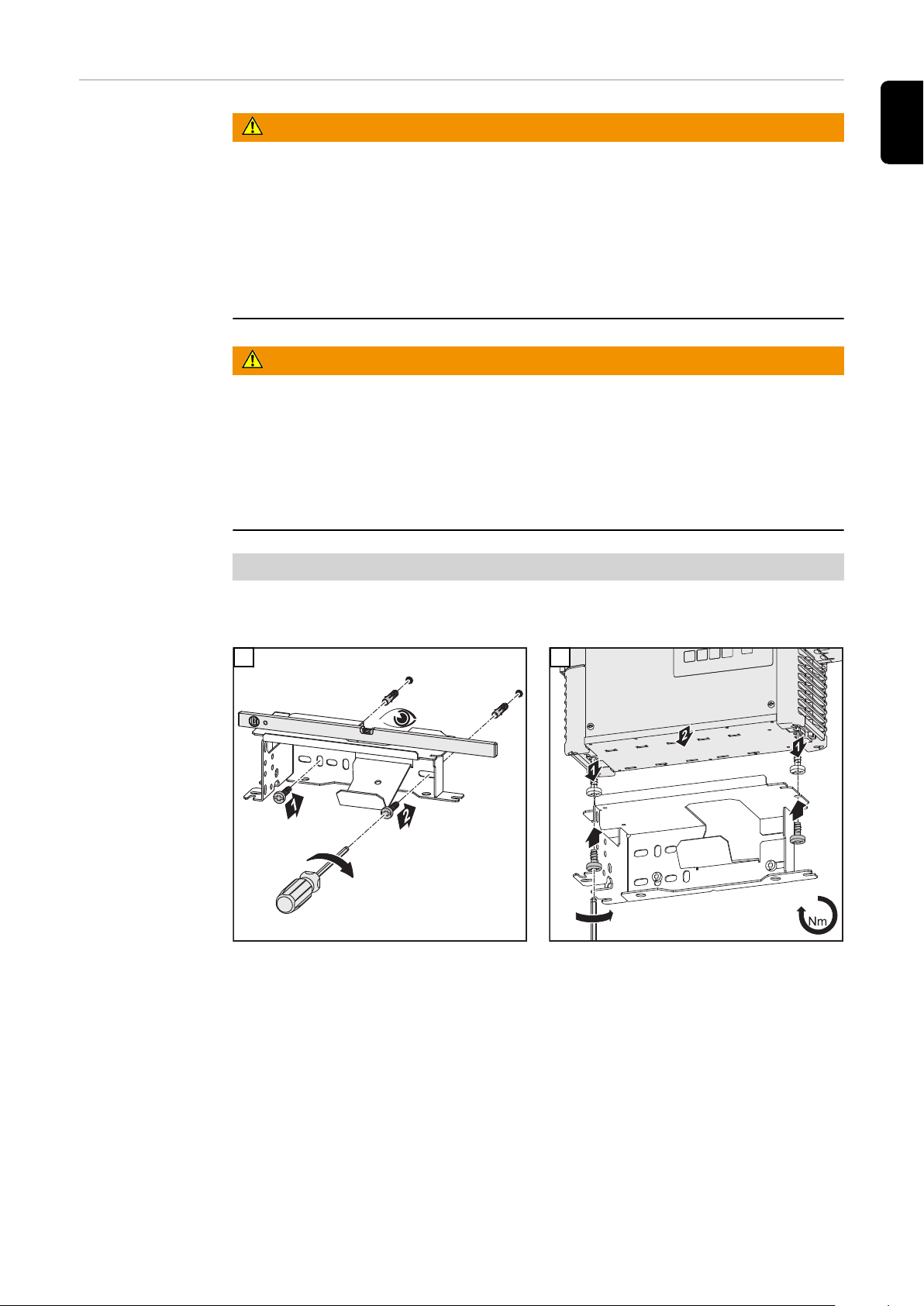
Wall and floor
*
TX25
3
3
3
*
*
bracket
WARNING!
Danger due to device toppling over.
This may result in serious injury and damage to property.
This installation must only be carried out by trained and qualified personnel.
▶
Take note of the safety rules in the charger Operating Instructions.
▶
Different wall plugs and screws are required depending on the supporting
▶
surface.
Wall plugs and screws are therefore not included in the scope of supply.
▶
The installer is responsible for selecting the correct wall plugs and screws.
▶
WARNING!
Danger due to objects falling or toppling over.
This may result in serious injury and damage to property.
Ensure that all screw connections are secure.
▶
Use only with the charger provided by the manufacturer.
▶
Ensure the device is level when mounting.
▶
If the device is mounted on the wall, ensure the wall is capable of supporting
▶
the weight of the device.
Weight of wall bracket:
EN
3 kW 1.35 kg (2.98 lb)
1
2
15

3 kWmm (in.)
417 (16.42)
182 (7.17)
38 (1.5) 123,5 (4.86)
40 (1.57) 89,5 (3.52)38 (1.5)
11 (.43)
8,5 (.33)
342 (13.46)
220 (8.66)
123 (4.84)
110 (4.33)
198 (7.8)
283 (11.14)
38 (1.5)
20 (.79) 90 (3.54)
38 (1.5)
20 (.79)
24,5 (.96)
76 (2.99)
16
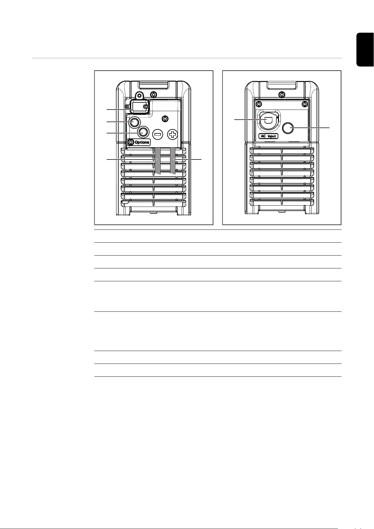
Control elements and connections
(3) (4)
(1)
(2)
(2)
(5)
(6)
Controls and
connections
EN
No. Function
(1) (+) Charging lead
(2) (-) Charging lead
(3) Position for options
(4) USB port
The USB port allows a USB flash drive to be used to update the device
and also to log the charging parameters while charging is in progress.
(5) Cover for option connector and charging leads *
The option connector can only be accessed by removing the cover (4). The
warning notices in the "Safety" section of the "Options" chapter must be
obeyed.
(6) Blanking cover
(7) Mains cable
17
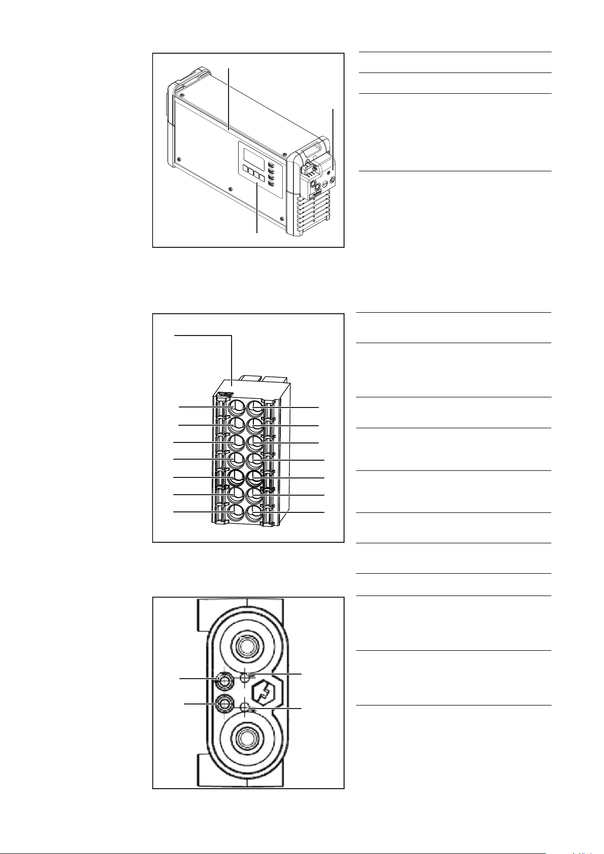
(7)
(8)
(9)
No. Function
(13)
(11)
(9)
(7)
(5)
(14)
(12)
(10)
(8)
(6)
(3) (4)
(1) (2)
(A)
(B)
(12)
(6)
(8)
(8) Control panel
(9) Optional LED strip
Lights up in different colours
depending on the state of
charge, as explained in the
"Control panel" section
The option plug (A) is located behind the cover on the front of the device, upon
which the charging leads can be found. For the CAN connection area, the warning
notices in the "Safety" section of the "Options" chapter apply.
Charging plug
18
(13) Status 3
LED RED
(11) Status 1
LED
GREEN
(14) Status 4
LED BLUE
(12) CAN 2
GND
Cable
brown
(9) CAN 1
(10) + 13 V
GND
(7) CAN 1 Low (8) CAN 2 Low
Cable yellow
(5) CAN 1
High
(6) CAN 2
High Cable
green
(3) Not as-
signed
(1) Not as-
signed
(B) Detect
Cable
white
(4) Not as-
signed
(2) Not as-
signed
(6) CAN 2
High
Cable
green
(12) CAN 2
GND
Cable
(8) CAN 2 Low
Cable yellow
brown
The Detect cable (B) is not needed on
the charger in this application. The Detect cable (B) is present on the charging plug, but not on the option plug
(A).

2
1
TX25
(1)
Control panel
(1) (8)
(7)
(6)
(5)
(4)(3)(2)
The cover (1) for the USB port can be
secured with a screw.
EN
No. Function
(1) Display
Displays the current charging parameters
Displays settings
(2) "Menu" key
Selects the desired menu
Selects the appropriate symbol to return to the previous display
(3) "Up/Down" keys
Selects the desired menu item
Sets the desired value
19

(4) "Stop/Start" key
For interrupting and resuming the charging process
Confirms a menu item or setting
(5) "State of charge"/"Battery cooled down" indicator (blue)
Depending on the setting, it signals the following battery conditions, according to the "Display" chapter, "Additional functions" section:
Blue state of charge LED setting: signals that the state of charge has exceeded a particular % value during the charging process.
Blue time/temperature LED setting: indicates that a battery has cooled
down and is ready for use.
On steady: after charging has finished, the set cooling time or optionally
the battery temperature has been reached.
(6) "Fault" indicator (red)
On steady: the charger outputs an error. The current conditions do not al-
low proper charge. While the red indicator is on, charging cannot take
place (charging interrupted). The relevant status code appears in the display.
Flashes briefly every 3 seconds: the charger outputs a warning. Charging
is continued despite the adverse charging parameters. The relevant status
code and the state of charge appear alternately on the display.
(7) "Charge" indicator (orange)
Lit: during charging
Flashes: if charging has been interrupted
(8) "Battery charged" indicator (green)
On steady: charging ended
20
Charging the battery
EN
Charging
WARNING!
Danger due to improper handling of the lithium battery.
This may result in serious injury and damage to property.
Note the following points without exception:
▶
Only connect lithium batteries that have been approved by the manufacturer
▶
to the charger.
Never expose the lithium battery to naked flames. Excessive heat can cause
▶
the battery to ignite or explode.
If the lithium battery becomes damaged due to improper handling, poison-
▶
ous substances can escape which are harmful to health.
Do not drop the lithium battery into water. This may lead to a short circuit.
▶
This in turn can cause the battery to become hot, ignite or explode.
Do not charge batteries with visible damage.
▶
WARNING!
Danger due to a faulty battery.
This may result in serious injury and damage to property.
Before charging, ensure that the battery is in full working order.
▶
NOTE!
Danger due to very dirty charging plug contacts.
This can result in damage to property.
The resulting increase in contact resistance can lead to overheating and sub-
▶
sequent destruction of the charging plug.
Keep the charging plug contacts free from impurities and clean them if ne-
▶
cessary.
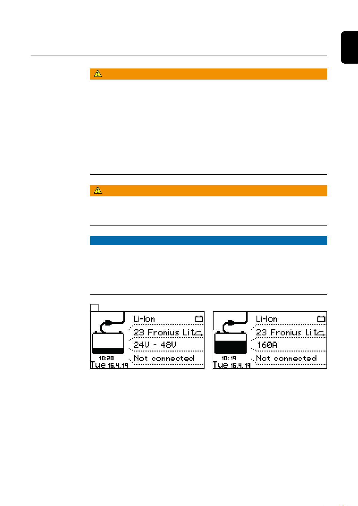
Connect the charger mains plug to the electrical mains supply
1
The display appears in standard mode. The display shows the charger parameters:
Type of battery (Li-Ion)
-
Charging characteristic, e.g. Fronius Li-Ion
-
Charger voltage range, alternates with the maximum output current, or only
-
the battery nominal voltage if a battery is connected
Connection status:
-
Not connected, or
Connected
Day of the week, date and time
-
The charger parameters can be set individually. More information on the charger
parameters can be found under "Configuration mode" in the "Display functions"
21

chapter. Ensure that the battery to be charged matches the configuration of the
battery charging system.
Plug in the charging plug
2
The charger detects that the battery is connected and starts charging. If start-up
delay is activated, then charging will start at the end of the set delay time. For
more information, see "Configuration mode" in the "Display" chapter.
During the charging process the display shows the following values:
Current charging current (A)
-
Current charging voltage (V)
-
Battery temperature (°C / °F)
-
Current state of charge (%)
-
The time (hh:mm) since charging started
-
The remaining charging time (hh:mm)
-
(provided the battery is sending this information to the charger)
If set:
-
Primary current limit (A)
Power limitation through calendar setting (kW)
When the primary current limit or calendar-based power limitation are enabled,
the respective limit value is shown on the display while charging is in progress. If
both functions are enabled at the same time, the lower limit is shown.
If the blue indicator is set to "state of charge" (see "Additional functions" in the
"Display" chapter), the blue indicator lights up once the state of charge exceeds a
defined % value.
The battery symbol indicates the current state of charge. The battery state of
charge is stated as a percentage.
If the charging process is interrupted because the "Stop / Start" button was
pressed, the display shows that the charging process has been stopped.
As soon as the battery is fully charged,
the green "Battery charged" indicator
lights up on the control panel and the
charging current is no longer displayed.
22

The green "Battery charged" in-
-
dicator is on
The battery is always ready to
-
EN
use
The battery can remain connec-
-
ted to the charger for as long as
required
Interrupting
charging
To interrupt the charging process:
Press the "Stop/Start" key
1
While the charging progress is interrupted:
The "Charge" indicator (yellow) flashes
To resume the charging process:
Press the "Stop/Start" key again
2
As long as a battery is connected to the charger, only the charging process can
be interrupted and resumed using the "Stop/Start" key. Display modes can be
changed using the "Menu" key as described in the "Display" section, but this is
only possible when there is no battery connected to the charger.
23

Stopping charging
WARNING!
Danger when disconnecting the charging cables.
This can result in severe personal injury and damage to property due to sparking.
Before disconnecting the charging plug, first stop the charging process by
▶
pressing the "Stop / Start" key.
As soon as the battery is fully charged, the following indicator lights up:
"Battery charged" indicator (green)
-
Depending on the blue indicator setting, this will also light up if
The state of charge has exceeded a specific value
-
The set battery cooling time has been reached, or optionally
-
the set battery temperature
To stop the charging process:
Press the "Stop/Start" key
1
Unplug the charging plug
2
When the charging contacts are open, the automatic open circuit voltage detection ensures that the charging contacts are de-energised.
24
Display
EN
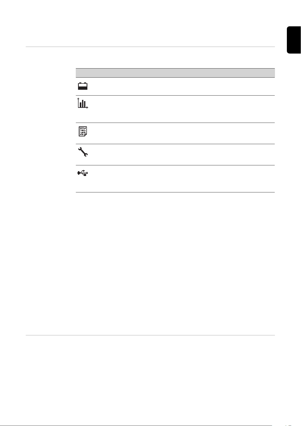
Overview of display modes
The device has the following display modes:
No. Function
Standard mode
In standard mode the display shows the charging parameters.
Statistics mode
Visualises the frequency of the device operating modes and shows the
total number of charging actions. Also shows an overview of the total
and average Ah produced and energy consumed per charge.
History mode
Provides information about the parameters for all the stored charging
processes.
Configuration mode
Configuration mode enables all the settings for the device and the
charging process to be adjusted.
USB mode
USB mode enables a device to be updated, device configurations to be
saved and loaded, and the charging parameters to be recorded during
the charging process - all using a USB flash drive.
As long as a battery is connected to the charger, the charging process can only
be interrupted and resumed using the "Pause/Start" key. Display modes can be
changed using the "Menu" key as described in the following sections that explain
the individual modes, but this is only possible when there is no battery connected
to the charger.
During a pause in the charging process the menu selection is available, however
only in a limited form. In this case the display modes described below are available as follows:
Statistics mode and history mode remain unrestricted.
In configuration mode the following data is available:
Date and time
-
Device serial number
-
Hardware version and serial number
-
Software: main software, secondary software, primary software and charac-
-
teristic block version
In USB mode all options except for "Update" and "Load configuration" are available.
Standard mode Once the mains plug has been connected to the electrical mains supply, the dis-
play will automatically operate in standard mode.
25

Menu selection
In standard mode, the display shows the following charger parameters:
Type of battery (Li-Ion)
-
Charging characteristic, Fronius Li-Ion (CAN)
-
Charger voltage range, alternates with the maximum output current, or only
-
the battery nominal voltage if a battery is connected
Connection status:
-
Not connected, or
Connected
Day of the week, date and time
-
The charger parameters can be set individually. More information can be found in
the "Configuration mode" section.
Change from standard mode to the menu selection as follows:
Press and hold the "Menu" key for approx. 5 seconds.
1
Change from all other modes to the menu selection as follows:
Briefly press the "Menu" key.
1
To select the desired mode:
Use the "Up/Down" keys to select the symbol for the desired mode.
2
e.g. the battery symbol for standard mode
-
Use the "Pause/Start" key to confirm the "Tick" symbol.
3
Statistics mode In statistics mode, horizontal bars dis-
play the frequency of the following
device operating statuses:
Idle
-
Charging
-
Charge Finished
-
Cooldown
-
Error
-
26

Use the "Up/Down" keys to toggle between page 1/2 and
1
page 2/2
Page 2/2 shows the following values:
Total number of charges
-
Total Ah output
-
Average Ah output per charge
-
Total energy consumed (kWh)
-
Average energy consumed (kWh)
-
per charge
The consumed energy display is a standard value and can deviate by up to 5%
from the actual amount of energy. At lower power levels the deviation may be
higher.
History mode History mode provides information about the parameters for all the stored char-
ging processes. In order to show changing or different displays, two versions of
the display window are shown below:
EN
Use the "Up/Down" keys to scroll between the pages for
1
each stored charging process
Text content of the display window:
Start date of charge, e.g. Mon 20/08/2014
-
Duration of charge, e.g. 3h25min or charging start time, e.g.: 16:08
-
State of charge at charge start, e.g. 23%
-
State of charge at charge end, e.g. 100%
-
Voltage at charge end, e.g. 58.6 V
-
Consumed Ah, e.g. 410 Ah
-
Consumed kWh, e.g. 20 kWh
-
Battery ID, e.g. 12345678X
-
Symbols shown
Full battery:
-
Charging has been completed
Empty battery:
-
Charging has not been completed
27

Symbols shown
Exclamation mark with number:
-
Warning has been output with the corresponding status code.
More information can be found in the "Status codes" section.
Symbol with number:
-
Error has been output with the corresponding status code. More
information can be found in the "Status codes" section.
Key symbol with a tick:
-
Charging was stopped properly using the "Stop/Start" key
Key symbol with a cross:
-
Charging was stopped without using the "Stop/Start" key
Configuration
mode
Configuration mode provides the following setting options:
"Charging settings": charge settings
-
Additional settings:
-
Time delay
-
Calendar
-
Disable Start button
-
Check DC connection
-
"Additional functions": Additional functions
-
Blue LED
-
External start/stop
-
External lamp
-
CAN
-
"General options": General settings
-
Language
-
Contrast
-
Time (hh:mm:ss), time zone, daylight saving time / normal time
-
Date (dd:mm:yy)
-
Length of charging cable (m)
-
-
Charging cable cross section (mm2)
AC current limitation
-
Unit for temperature values
-
Code for accessing the configuration menu activated/deactivated
-
Time interval for the parameters recorded on the USB flash drive (s)
-
Reset statistics
-
Reset history
-
"Reset Settings": resets settings to those when the charger left the factory or
-
optionally to the manufacturer's defaults
includes a double-check prompt ("OK?") that requires the operator to re-
-
confirm that this step is intended
28
First the screen will appear in its initial
format, showing the date, time and
software version.

The "Up/Down" keys can be used to retrieve the following
1
information:
Serial number of the charger plus serial number and
-
version of the configuration memory
PC board for controller/power electronics: hardware
-
version and serial number
Software: main software, secondary software, primary
-
software and characteristic block version
The procedure for opening the configuration menu is as follows:
Press the "Stop/Start" key
1
You will be prompted to enter a code:
EN
The code required is "1511", and is entered as follows:
Using the "Up/Down" keys, enter the first digit of the code
1
Press the "Menu" key to move to the next digit of the code
2
Continue following the procedure described above until the
3
complete code has been entered
Use the "Stop/Start" key to confirm the code entered
4
29

You will now be prompted to select one of the main menu items for the configuration mode:
When you select a menu item you
may be presented with a symbol
prompting you to read the Operating
Instructions. Confirm this prompt by
pressing the "Stop/Start" key again.
The procedure for navigating the configuration menu and its submenus is as
follows:
Use the "Up/Down" keys to select the desired menu item
1
Use the "Stop/Start" key to confirm the menu item, and re-
2
confirm any double-check prompt (e.g. "OK?")
Use the "Up/Down" keys as necessary to choose an item, e.g.
3
"Off/On" or enter a value
Use the "Stop/Start" key to confirm what you have entered
4
If the cursor moves to another setting or position after con-
5
firmation of the previous setting, repeat the procedure described in points (3) and (4)
To exit the current menu:
Press the "Menu" key to return to the higher-level menu
6
Charging settings
30
The following section provides a detailed explanation of the "Charging settings"
menu item in configuration mode. Navigation is carried out as described in the
"Configuration mode" section.

Select the "Charging settings"
1
menu item
A list appears with the following selection options:
"Delay"
"Charge start delay"
Delay time (minutes) between the activation time of the charge start and the
-
actual charge start.
EN
“Charge end delay”
Delay time (minutes) between the signaled end of charge (e.g. green indicat-
-
or) and the actual end of charge.
"At mains failure restart charging"
If this option is activated, the charging process is automatically restarted
-
after a fault in the electrical network as soon as the electrical network is
available again.
"At mains failure"
Restart charging
-
Automatic/continue charging
-
If the "Restart charging" option is activated, the charging process is automatically restarted after a fault in the electrical network as soon as the electrical network is available again.
If the "Automatic/continue charging" option is activated, the charging process is
automatically continued after a fault in the electrical network as soon as the
electrical network is available again.
"Calendar" - optional
The calendar function enables charging to be started automatically according to
the following criteria:
Time window within which no charging should take place when a battery is
-
connected
Time window within which charging should take place when a battery is con-
-
nected
31
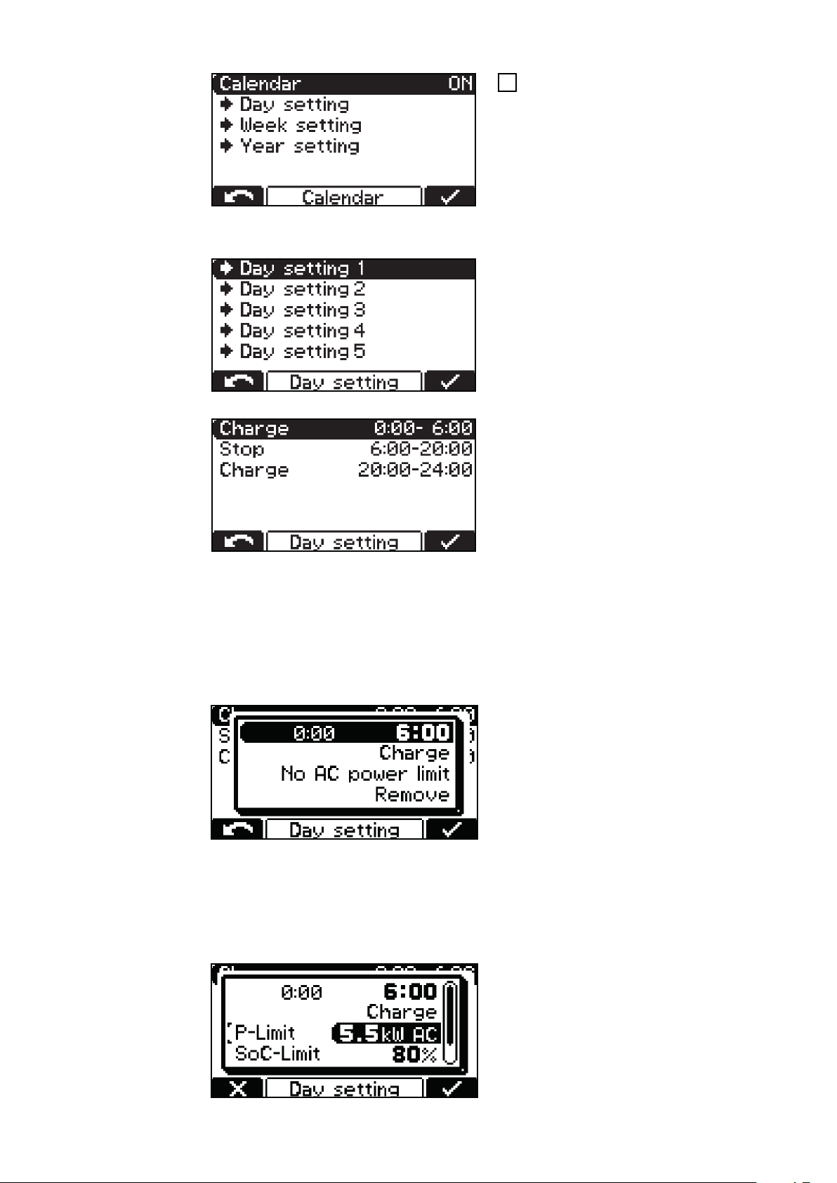
To activate the calendar function,
1
select and confirm the "ON" setting
The following settings are possible within the calendar function:
"Day setting 1-7":
The day settings allow up to 7 different charging phase time profiles to
be defined.
"Charge":
Time window within which charging
-
should start
(e.g: 0:00-6:00, 20:00-24:00)
Stop:
Time window within which no char-
-
ging should take place
(e.g: 6:00-20:00)
Please note! Ongoing charges are influenced by the set time windows.
If a battery is connected at 05:45 in the above example, charging is stopped
-
by the specified end time (6:00 in the example) of the set time window. The
subsequent charging phase resumes the charging process.
If the battery is connected within the stop time window, charging will start
-
automatically in the next time window.
Each time window can be adjusted in
15-minute increments. It is possible to
assign up to 15 time windows per day
setting.
For each time window, either Charge or
Stop can be selected.
"AC power limit"
Requirement: "Charge" is selected
-
A maximum AC power can be set per time window, which the device must
-
not exceed in this phase.
32
The "AC power limit" can be adjusted
in increments of 0.5 kW.
The minimum and maximum values differ for the different device classes.
The minimum value is approx. 25% of
the maximum output power of the
device concerned.
Please note! The efficiency of the device can be negatively influenced by a set
power limit.
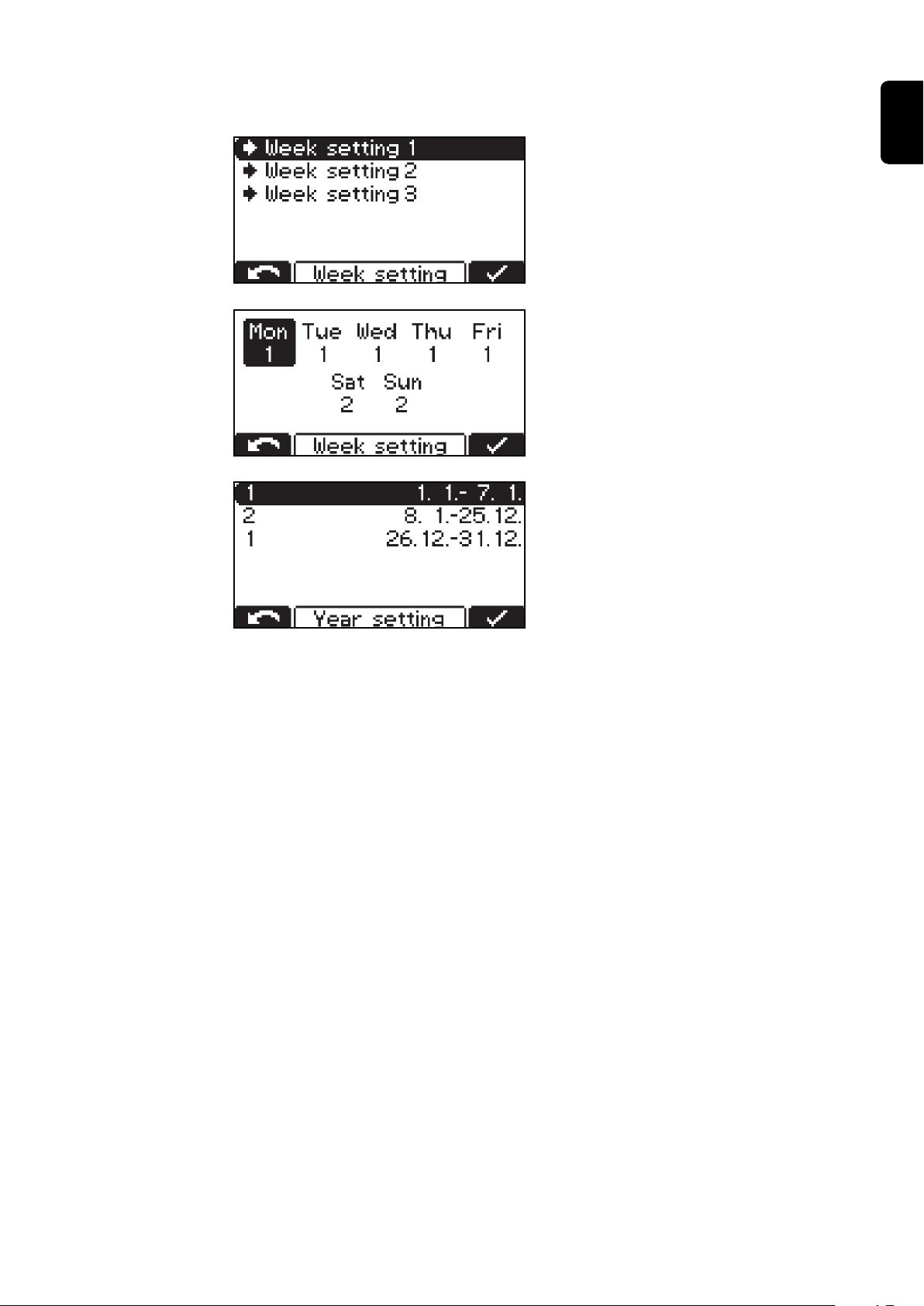
"Week setting":
It is possible to configure 3 differ-
-
ent week settings.
Each day of the week can be assigned
one of the previously created day settings.
"Year setting":
It is possible to assign a week set-
-
ting to several calendar periods
(e.g. 1.1. - 7.1.).
EN
When the calendar function is activated, a calendar symbol appears in the display.
"Disable Start Button"
ON:
-
It is not possible to start the charging process using the "Stop/Start"
-
button, which prevents unauthorized access, for example.
OFF:
-
It is possible to start the charging process using the "Stop/Start" button
-
"Check DC Connection"
ON:
-
An error is output if an open circuit is detected several times per charge
-
and the battery remains connected (e.g. bad plug contact)
OFF:
-
No error is output when an open circuit is detected.
-
33

Additional functions
The following contains a detailed description of the "additional functions" menu
item in configuration mode. Navigation is performed as described in the "Configuration mode" section.
Select the "additional functions"
1
menu item
A list appears with the following selection options:
Blue LED:
Setting of the "Blue LED" indicator:
-
Governed by state of charge: set value is the battery state of charge in %.
-
The blue indicator lights up once the state of charge exceeds the set percentage value while charging is in progress. The blue indicator will never
light up if the value is set to 100%.
Setting the time (minutes) that should be allowed to pass before the
-
"Blue battery cooled" down indicator should come on to signal that a
battery has cooled down sufficiently. The time from the end of charging
is used as the setting.
Governed by temperature: the set value is a temperature below which
-
the blue "battery cooled down" indicator should come on to signal that a
battery has cooled down sufficiently.
External start/stop:
34
The following settings are available when external start/stop is selected:
Start:
-
normal ON:
Charging starts when an external switch is closed and a battery is detec-
-
ted
Or when the charging plug is connected by closing the auxiliary contacts
-
and a battery is detected
normal OFF:
Charging starts when a battery is connected
-
Stop:
-
normal ON:
Charging is interrupted when an external switch is opened
-
Or when the charging plug is disconnected by opening the auxiliary con-
-
tacts
normal OFF:
Opening of an external switch or the auxiliary contacts is ignored
-
Button:
-
The function of the "Stop/Start" key can be simulated using an external button
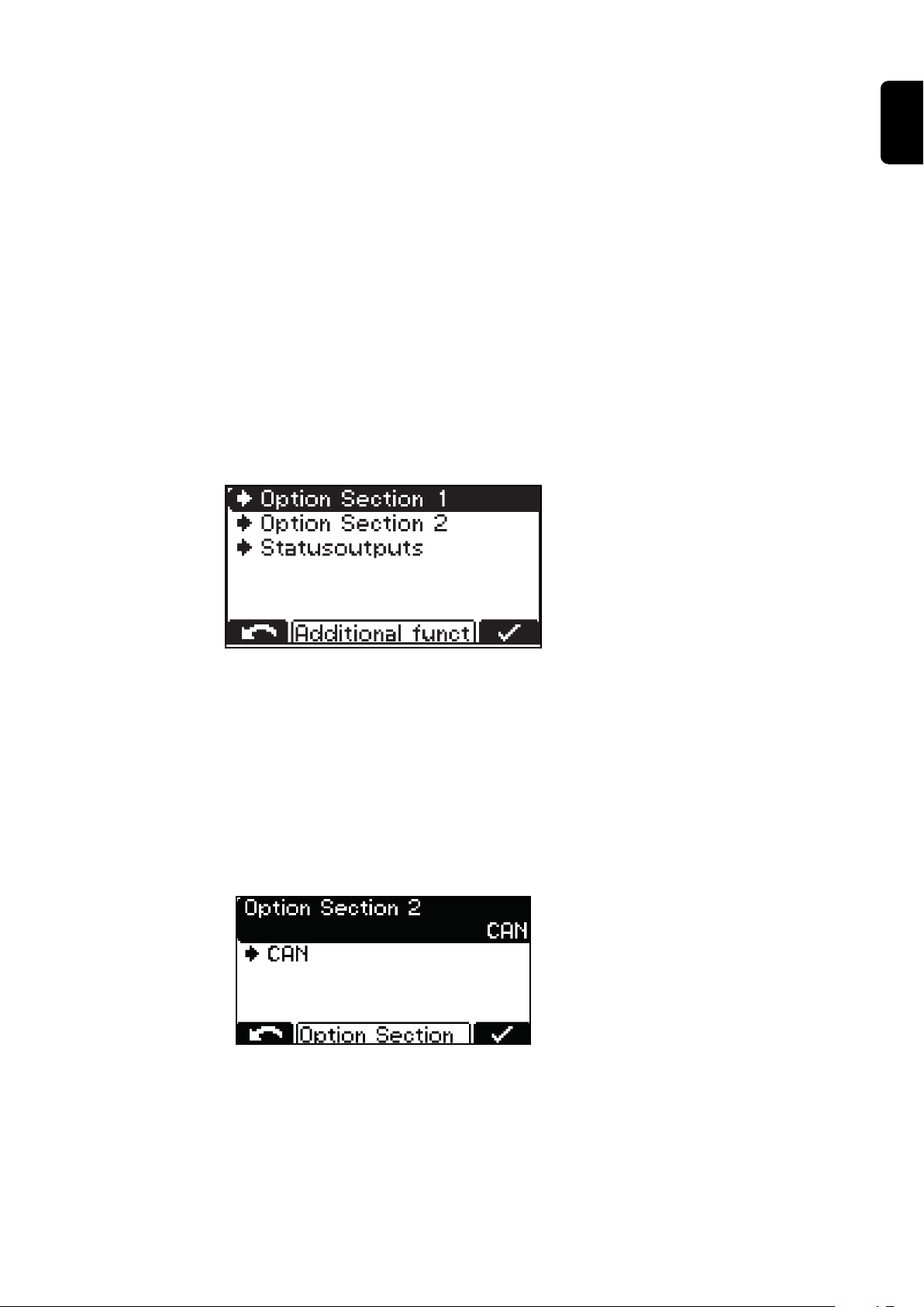
Option Section:
EN
"Option Section 1" is currently not used for any adjustable settings.
The following can be adjusted under "Option Section 2":
CAN2 protocol
-
(for Li-Ion protocols the CAN2 interface is used as standard.)
The following can be adjusted under "Statusoutputs":
Setting for external lamp
-
(normal or RGB)
CAN submenu item:
The CAN protocol to be used can be set under the "CAN" submenu item. This depends on the respective application.
35

A tick appears in the "Status" area as
soon as a CAN connection has been
successfully established. Otherwise a
"x" is shown.
To view the protocol version number:
Press the "Stop/Start" key
-
The "-> Statistics" area contains further information on the CAN communication.
36

General settings Detailed explanation of the "general options" menu item in configuration mode.
Select the "general options" menu
1
item.
A list appears with the following selection options:
Language
-
Display settings
-
Contrast
-
LED brightness
-
Show Ah at charge end
-
ON/OFF
Time and Date
-
daylight saving time / normal
-
time
Predefined time zones
-
User-defined time zones
-
EN
Charging cable:
Cable cross section:
Cross-section of the charging cable (mm²)
-
AC current consumption:
Basic length of charging cable (m)
-
Adapt the maximum consumed
-
device current to the on-site electrical installation or the device
connector fitted on the device.
37

The minimum and maximum values
-
differ depending on the different
device classes. The minimum value
is approx. 25% of the maximum
nominal current of the charger.
Temperature:
Temperature in °C / °F
-
Code:
Code entry required / not required to access configuration mode ("Code
-
ON / OFF")
USB Logging Time:
Time interval (s) for recording
-
charging parameters on the USB
flash drive (USB Logging Time)
Reset statistics
Reset history
For more detailed information on the statistics and history, please refer to the
"Statistics mode" and "History mode" sections.
38
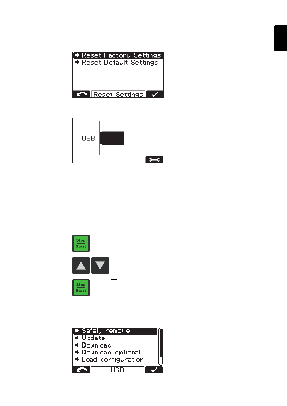
Reset settings The menu item below "General options" offers two alternative ways of resetting
all the settings:
Reset Factory Settings:
Resets to factory settings.
-
Reset Default Settings:
Resets settings to the manufac-
-
turer's defaults.
USB mode In USB mode, the display shows
whether or not a USB flash drive is
connected.
The USB flash drive must conform to
the following specifications:
Formatting: FAT32
-
32 Gigabyte maximum
-
Non multi-partitioned
-
EN
The I-SPoT VIEWER software supports the visualisation and evaluation of data
on the USB flash drive. The I-SPoT VIEWER software can be found online at the
following address: http://www.fronius.com/i-spot.
Only insert the USB flash drive when charging is not in progress or if the charging
process has been interrupted.
If the charging process is only interrupted, not completed, it is only possible to
read out data. A new update or configuration cannot be loaded.
Use the "Stop/Start" key to access the following settings
1
Use the "Up/Down" keys to scroll between the settings
2
Use the "Stop/Start" key to confirm the desired setting
3
A USB flash drive may be connected while charging is in progress, after the
"Stop/Start" key has been pressed. However, this can only be to read out data. An
update or new configuration cannot be loaded.
39
Safely remove
-
Safely remove the USB flash drive as soon as the desired action has been
completed.
Update
-
A list of the suitable update files stored on the USB flash drive opens.
Select and confirm the desired file in the same way as scrolling through the
settings.
Do not change the automatically assigned file names of the update file!
Download
-
The data relating to the logged charging parameters stored in the device's
datalogger is saved to the USB flash drive for the I-SPoT VIEWER.
Events are also saved.
The following time ranges can be selected for the datalogger:
1 month
-
3 months
-
All
-
Since the last save
-
Download optional
-
The following options are available:
I-SPoT VIEWER
-
The logged data is saved in the same way as for the "Download" function,
but saving only the I-SPoT VIEWER data.
Save Datalogger
-
The logged data is saved in the same way as for the "Download" function,
but is saved not in the I-SPoT VIEWER format, but as ".csv" files
(Automatically created folder structure for the .csv files: *
Fronius\<device serial number>\Charges\<yyyymmdd>\<hhmmss.csv>
Save events
-
Events are saved to the USB flash drive.
Save configuration
-
The device settings are saved to the USB flash drive.
40
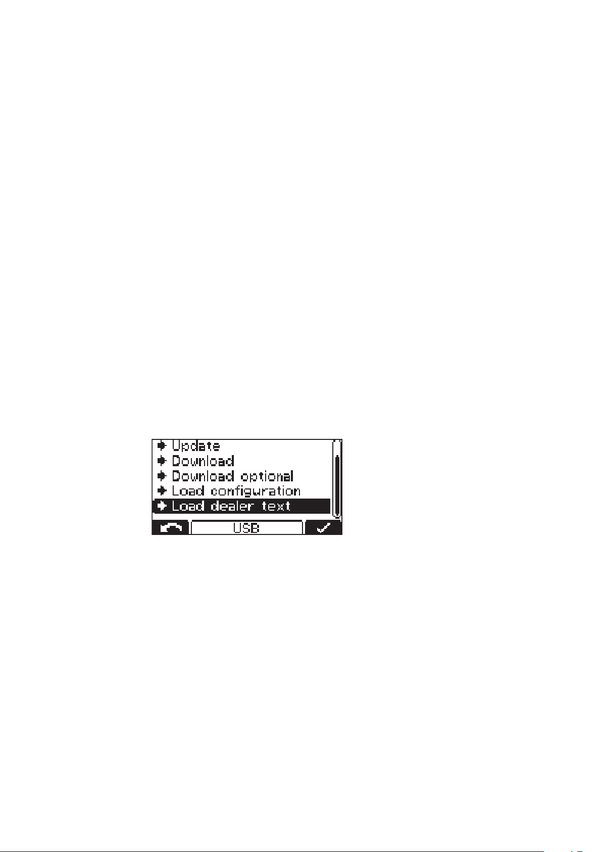
Load dealer text
-
A text file can be loaded from the USB flash drive that is displayed as soon
as the device enters an error state. The text file can, for example, contain the
contact details of the dealer. The file must be saved on the USB flash drive
as a ".txt" file in "unicode" format. The file name must be "dealer.txt". The
number of characters is restricted to 99.
* If a USB flash drive is connected while charging is in progress, the .csv files
are saved directly to the USB flash drive. The folder structure here is also
created automatically and differs due to the presence of the "Datalog"
folder instead of the "Charges" folder.

Status codes
If a fault occurs during operation, specific status codes may be displayed. Faults
can result from the following:
Battery fault
-
The voltage of the connected battery is unsuitable.
-
The device has overheated.
-
There is a software or hardware fault.
-
Battery fault:
If the battery signals a fault, the battery charger displays this fault as a battery
fault including the corresponding fault number for the battery. The respective
fault is explained in the battery's Operating Instructions.
If an error message appears on the display and if you cannot resolve the error
yourself:
Note the displayed status code: e.g. "Statecode (31)".
1
Note the configuration of the device.
2
Contact your authorised service centre.
3
Freely-defined text, which could for example include the contact details of
the distributor, can be displayed if the device is in an error state.
EN
Status codes caused by external factors
No. Cause / Remedy
(11) Check mains voltage
(12) Check mains (phase failure)
(13) External temperature sensor faulty
(14) Electrolyte circulation faulty (pressure switch not switching)
(15) Control voltage not detected
(16) External start/stop is not closed.
(17) Open circuit voltage detection triggered more than once during charging
(e.g. worn charging contacts)
Status codes in the event of a battery fault
No. Cause / Remedy
(22) Battery undervoltage
(23) Battery overvoltage
(24) Battery too hot (with external temperature sensor only)
(25) Battery too cold (with external temperature sensor only)
41

(26) Cell fault detected
(27) Battery not supported
(28) Battery heavily discharged - safety charging is being carried out
(29) Battery is connected with reverse polarity
(30) Thermal runaway
Status codes in the event of a CAN fault (battery)
No. Cause / Remedy
(51) Battery not responding
(52) Battery data cannot be requested
(53) Battery voltage not supported
(54) Communication fault
(55) Battery fault
(56) Battery does not switch on
(57) Message time limit exceeded
(58) Registration failed
Status codes in the event of a gateway fault
No. Cause / Remedy
(101) Setting CAN Connect is active and no CAN connection to the gateway
could be established for at least 2 minutes.
(102) No gateway connection to the back-end.
Status codes in the event of a charging error
No. Cause / Remedy
(31) Timeout in I1 phase
(32) Timeout in U1 phase
(33) Battery overvoltage in the I2 phase
(34) Ah limit exceed
(35) Timeout in I2 phase
42
(36) Target voltage in I2 phase not reached (with format characteristic only)
(37) Problem with RI charge
(38) Set charging time cannot be reached
(39) Timeout in RI charge

Status codes in the event of a fault in the primary circuit
No. Cause / Remedy
(500) Module 1 (top) temperature sensor faulty
(501) Module 2 (bottom) temperature sensor faulty
(502) PCB temperature sensor faulty
(503) Primary overtemperature
(504) Fan blocked/faulty
(505) Intermediate circuit over/undervoltage
(506) Intermediate circuit imbalance
(507) Primary supply voltage outside the tolerance
(508) Power failure
(509) Wrong device configuration
(510) Primary EEPROM faulty
(527) Phase shifter overcurrent
(528) Charging relay switched off during load operation
(530) Communication error
EN
(532) Microcontroller error (e.g. division by 0)
(533) Reference voltage outside the tolerance
(534) Start-up error
(535) PFC overcurrent
(536) Phase shifter or PFC faulty
Status codes in the event of a fault in the secondary circuit
No. Cause / Remedy
(520) Secondary temperature sensor faulty
(521) Secondary overtemperature
(522) Output fuse faulty
(523) Secondary supply voltage outside the tolerance
(524) Secondary reference voltage outside the tolerance
(525) Current offset
(526) Current offset outside the tolerance
(527) Power module overcurrent (primary)
(529) No secondary communication
(530) No primary communication
(531) Secondary EEPROM faulty
(532) Microcontroller fault
43

(537) Voltage measurement faulty
(570) Secondary relay cannot be switched
(571) ADC/SPI error
Status codes in the event of a fault in the controller
No. Cause / Remedy
(540) Configuration memory chip missing/faulty
(541) No secondary communication
(542) Secondary initialisation failed
(543) Program/memory fault in characteristic control
(544) Program/memory fault in characteristic control
(545) Primary initialisation failed
(546) Update failed
(547) Load/save settings failed
(548) Load/save characteristic settings failed
(549) Charging could not be resumed after a power failure
(550) Time not set
(551) Hardware change detected
(552) Configuration memory chip invalid
(553) Primary update failed
(554) Fault in the master-slave communication
(555) Incorrect device software
(557) Interruption of the InterLock communication
(558) The second device, which is connected via the InterLock option, has an er-
ror
(559) The second device, which is connected via the InterLock option, is incom-
patible with this device
44

Options
Safety In order to connect optional components, it may be necessary to open the hous-
ing. The following warning notices must be obeyed:
WARNING!
Danger from electric shocks.
This can result in serious injury or death.
The housing must never be opened by anyone other than a service technician
▶
trained by the manufacturer.
The device must be disconnected from the grid before starting any work with
▶
the housing open.
A suitable measuring instrument must be used to ensure that electrically
▶
charged components (e.g. capacitors) are fully discharged.
Use an easily legible and understandable warning sign to ensure that the
▶
device is not reconnected to the grid before all the work has been completed.
WARNING!
EN
Danger due to work that has been carried out improperly.
This can result in serious injury and damage to property.
All work involved with connecting optional components must only be carried
▶
out by qualified specialist technicians.
If Installation Instructions or User Information is available for the optional
▶
component concerned, all warning notices and instructions therein must be
obeyed.
In the case of all optional components with electrical connections, once the
▶
connection work is complete, a safety inspection must be carried out in accordance with relevant national and international standards and directives.
Further details on safety inspections can be obtained from your authorised
▶
service centre.
They will provide you with any documents you may require on request.
▶
WARNING!
Danger from devices falling or toppling over.
This can result in serious injury and damage to property.
Due to its weight, the device must be secured using suitable fittings to pre-
▶
vent it from toppling or falling over.
The wall and floor brackets provided by the manufacturer must be used.
▶
LED strip The LED strip acts as a status indicator and lights up in the same colours as the
display elements on the control panel. An LED strip including a diffuser is installed in the gap between the front wall and upper part of the housing.
Air filter In dusty environments, the air filter prevents the inside of the device from be-
coming dirty. This avoids a possible reduction in power and other problems. Detailed information can be found in the corresponding User Information.
Cleaning interval as required (manufacturer's recommendation: monthly)
45

"Mobile" kit A carrying strap makes it easier to move the device.
425 (16.73)
482 (18.98) 115 (4.53)
428 (16.85)
456 (17.95)
462 (18.19)
415 (16.34)
418 (16.46)
446 (17.56)
452 (17.80)
6,5 (.26)
38 (1.5)38 (1.5)
53.8
(2.12)
53.8
(2.12)
6,5 (.26)6,5 (.26)
76 (2.99)
205 (8.07)
76 (2.99)
14 (.55)
6,5 (.26)
14 (.55)
mm (in.)
Wall bracket The robust wall bracket ensures safe fitting on site. More information can be
found in the corresponding Installation Instructions.
Floor bracket The robust floor bracket ensures safe fitting on site. More information can be
found in the corresponding Installation Instructions.
Mounting plate The mounting plate may be used as a space-saving floor or wall bracket.
46

Technical data
EN
Selectiva 3 kW
Li-Ion
Mains voltage
1)
~ 230 V, ±15%
Grid frequency 50/60 Hz
Mains fuse protection
2)
max. 16 A
Minimum mains lead cross section 1.5 mm² (0.002325 in²)
Protection class I (with ground conductor)
Max. permitted mains impedance Z
3)
PCC
max
on
None
Standby usage 5 W
EMC device class A
Dimensions l x w x h 417 x 110 x 198 mm
(16.42 x 4.33 x 7.8 in.)
Pollution degree 3
Protection class
4)
IP21
Overvoltage category III
Operating temperature
5)
-20 °C to +40 °C
(-4 °F to 104 °F)
Storage temperature -25 °C to +80 °C
(-13 °F to 176 °F)
Relative humidity maximum 85%
Maximum altitude above sea level 2000 m (6561 ft.)
Marks of conformity according to rating plate
Product standard EN62477-1
1)
The device is approved for operation on neutral-earthed networks.
2)
The leakage current to earth is less than 3.5 mA.
3)
Interface to a 230/400 V, 50 Hz public grid
4)
For indoor use only, do not expose to rain or snow
5)
A high ambient temperature may result in power degradation (derating)
Max.
Device-specific
data
Max. AC
current
Max. AC
power
Nominal
voltage
charging
current Weight
Selectiva 2120 15.6 A 3320 W 24 V 120 A 8.7 kg
(19.18 lb)
Selectiva 4060 15.3 A 3270 W 48 V 60 A 8.7 kg
(19.18 lb)
6)
6)
With standard mains and charging leads
47
 Loading...