

Page 1
/ Perfect Charging / Perfect Welding / Solar Energy
Selectiva
2100 / 2120 / 2140 / 2160 / 2180
2200 / 4060 / 4075 / 4090 / 4120
4140 / 4160 / 8040 / 8060 / 8075
8090 / 8120 / 8140 / 8160 / 8180
Operating Instructions
EN
Battery charging system
42,0426,0151,EN 015-01042015
Page 2

0
Page 3

Dear reader,
Introduction Thank you for the trust you have placed in our company and congratulations on buying this
high-quality Fronius product. These instructions will help you familiarise yourself with the
product. Reading the instructions carefully will enable you to learn about the many different
features it has to offer. This will allow you to make full use of its advantages.
Please also note the safety rules to ensure greater safety when using the product. Careful
handling of the product will repay you with years of safe and reliable operation. These are
essential prerequisites for excellent results.
The latest version of the operating instructions can be found on the Fronius website
"www.fronius.com".
EN
Explanation of
safety symbols
DANGER! Indicates immediate and real danger. If it is not avoided, death or se-
rious injury will result.
WARNING! Indicates a potentially dangerous situation. Death or serious injury
may result if appropriate precautions are not taken.
CAUTION! Indicates a situation where damage or injury could occur. If it is not
avoided, minor injury and/or damage to property may result.
NOTE! Indicates a risk of flawed results and possible damage to the equipment.
IMPORTANT! Indicates tips for correct operation and other particularly useful information.
It does not indicate a potentially damaging or dangerous situation.
If you see any of the symbols depicted in the "Safety rules" chapter, special care is required.
1
Page 4

2
Page 5

Contents
Safety rules ................................................................................................................................................ 5
General ................................................................................................................................................. 5
Proper use ............................................................................................................................................ 5
Environmental conditions...................................................................................................................... 5
Mains connection.................................................................................................................................. 6
Dangers from mains current and charging current ............................................................................... 6
Dangers from acid, gases and vapours ................................................................................................ 6
General information regarding the handling of batteries....................................................................... 7
Protecting yourself and others .............................................................................................................. 7
Safety measures in normal operation ................................................................................................... 7
EMC Device Classifications.................................................................................................................. 8
EMC measures ..................................................................................................................................... 8
Data protection...................................................................................................................................... 8
Maintenance and repair ........................................................................................................................ 8
Warranty and liability............................................................................................................................. 8
Safety inspection................................................................................................................................... 9
Safety symbols...................................................................................................................................... 9
Disposal ................................................................................................................................................ 9
Copyright............................................................................................................................................... 9
General information ................................................................................................................................... 10
Mains connection.................................................................................................................................. 10
Correct battery configuration................................................................................................................. 10
Warning notices on the device.............................................................................................................. 10
Warning notices inside the device ........................................................................................................ 11
Setup regulations.................................................................................................................................. 11
Wall bracket .......................................................................................................................................... 12
Control elements and connections............................................................................................................. 15
Control elements and connections........................................................................................................ 15
Control panel......................................................................................................................................... 16
Charging the battery .................................................................................................................................. 18
Charging ............................................................................................................................................... 18
Interrupting charging............................................................................................................................. 19
Stopping charging................................................................................................................................. 19
Display ....................................................................................................................................................... 20
Overview of modes ............................................................................................................................... 20
Standard mode ..................................................................................................................................... 20
Menu selection...................................................................................................................................... 20
Statistics mode...................................................................................................................................... 21
History mode......................................................................................................................................... 21
Configuration mode............................................................................................................................... 22
-> Settings............................................................................................................................................. 25
Additional functions............................................................................................................................... 30
General settings.................................................................................................................................... 33
Reset settings ....................................................................................................................................... 33
USB mode............................................................................................................................................. 34
Status codes ......................................................................................................................................... 35
Options....................................................................................................................................................... 38
Safety.................................................................................................................................................... 38
Electrolyte circulation............................................................................................................................ 38
External start/stop................................................................................................................................. 39
Charging lights...................................................................................................................................... 40
Temperature-controlled charging.......................................................................................................... 40
Relay board........................................................................................................................................... 40
Aquamatic............................................................................................................................................. 41
Charging ............................................................................................................................................... 41
Charge 80%.......................................................................................................................................... 41
Charge finish......................................................................................................................................... 41
Main charge finished............................................................................................................................. 41
Common error message ....................................................................................................................... 41
Signal lamp ........................................................................................................................................... 41
EN
3
Page 6

Immobiliser............................................................................................................................................ 42
Battery cooled down ............................................................................................................................. 42
External air pump - electrolyte circulation............................................................................................. 42
LED strip ............................................................................................................................................... 42
Floor bracket......................................................................................................................................... 42
Wall bracket .......................................................................................................................................... 42
"Mobile" kit ............................................................................................................................................ 42
RCS 3.0 remote indication.................................................................................................................... 42
Technical data............................................................................................................................................ 43
Selectiva 8 kW ...................................................................................................................................... 43
Selectiva 16 kW .................................................................................................................................... 44
4
Page 7
Safety rules
EN
General
The device is manufactured using state-of-the-art technology and according
to recognised safety standards. If used incorrectly or misused, however, it can
cause:
- injury or death to the operator or a third party,
- damage to the device and other material assets belonging to the operating company,
- inefficient operation of the device.
All persons involved in commissioning, operating, maintaining and servicing
the device must:
- be suitably qualified,
- read and follow these operating instructions carefully.
The operating instructions must always be at hand wherever the device is being used. In addition to the operating instructions, attention must also be paid
to any generally applicable and local regulations regarding accident prevention and environmental protection.
All safety and danger notices on the device
- must be in a legible state,
- must not be damaged,
- must not be removed,
- must not be covered, pasted or painted over.
For the location of the safety and danger notices on the device, refer to the
section headed "General information" in the operating instructions for the device.
Before switching on the device, rectify any faults that could compromise safety.
This is for your personal safety!
Proper use
Environmental
conditions
The device is to be used exclusively for its intended purpose. Any use above
and beyond this purpose is deemed improper. The manufacturer is not liable
for any damage, or unexpected or incorrect results arising out of such misuse.
Proper use includes:
- carefully reading and obeying all operating instructions and safety and
danger notices
- performing all stipulated inspection and maintenance work
- following all instructions from the battery and vehicle manufacturers
Proper handling of the device is essential for it to function correctly. The device
must never be pulled around by the cable.
Operation or storage of the device outside the stipulated area will be deemed
as not in accordance with the intended purpose. The manufacturer shall not
be held liable for any damage arising from such usage.
For exact information on permitted environmental conditions, please refer to
the "Technical data" section.
5
Page 8

Mains connection
Devices with a higher rating may affect the energy quality of the mains due to
their current input.
This may affect a number of device types in terms of:
- connection restrictions
- criteria with regard to the maximum permissible mains impedance
- criteria with regard to the minimum short-circuit power requirement
*)
at the interface with the public grid
*)
*)
see "Technical data"
In this case, the plant operator or the person using the device should check
whether the device may be connected, where appropriate by discussing the
matter with the power supply company.
NOTE! Ensure that the mains connection is earthed properly
Dangers from
mains current
and charging current
Dangers from acid, gases and vapours
Anyone working with chargers exposes themselves to numerous dangers e.g.:
- risk of electrocution from mains current and charging current
- hazardous electromagnetic fields, which can risk the lives of those using
cardiac pacemakers
An electric shock can be fatal. Every electric shock is potentially life threatening. To avoid electric shocks while using the charger:
- do not touch any live parts inside or on the outside of the charger.
- under no circumstances touch the battery poles
- do not short-circuit the charger lead or charging terminals
All cables and leads must be secured, undamaged, insulated and adequately
dimensioned. Loose connections, scorched, damaged or inadequately dimensioned cables and leads must be immediately repaired by authorised personnel.
Batteries contain acid which is harmful to the eyes and skin. During charging,
gases and vapours are released that can harm health and are highly explosive
in certain circumstances.
- Only use the chargers in well ventilated areas to prevent the accumulation
of explosive gases. Battery areas are not deemed to be hazardous areas
provided that a concentration of hydrogen of less than 4 % can be guaranteed by the use of natural or forced ventilation.
- Maintain a distance of at least 0.5 m (19.69 in.) between battery and
charger during the charging procedure. Possible sources of ignition, such
as fire and naked lights, must be kept away from the battery
- The battery connection (e.g. charging terminals) must not be disconnected for any reason during charging
- On no account inhale any of the gases and vapours released
- Make sure the area is well ventilated.
- To prevent short circuits, do not place any tools or conductive metals on
the battery
6
Page 9

- Battery acid must not get into the eyes, onto the skin or clothes. Wear protective goggles and suitable protective clothing. Rinse any acid splashes
thoroughly with clean water, and seek medical advice if necessary.
EN
General information regarding the
handling of batteries
Protecting yourself and others
- Protect batteries from dirt and mechanical damage.
- Store charged batteries in a cool place. Self discharge is kept to a minimum at approx. +2 °C (35.6 °F).
- Every week, perform a visual inspection to ensure that the acid (electrolyte) level in the battery is at the Max. mark.
- If any of the following occurs, do not start the device (or stop immediately
if already in use) and have the battery checked by an authorised workshop:
- uneven acid levels and/or high water consumption in individual cells
caused by a possible fault.
- heating of the battery over 55 °C (131 °F).
While the charger is in operation, keep all persons, especially children, out of
the working area. If, however, there are people in the vicinity,
- warn them about all the dangers (hazardous acids and gases, danger
from mains and charging current, etc.),
- provide suitable protective equipment.
Before leaving the work area, ensure that people or property cannot come to
any harm in your absence.
Safety measures
in normal operation
- Chargers with a ground conductor must only be operated on a mains supply
with a ground conductor and a socket with a ground conductor contact. If the
charger is operated on a mains supply without a ground conductor or in a
socket without a ground conductor contact, this will be deemed gross negligence. The manufacturer shall not be held liable for any damage arising
from such usage.
- Only operate the charger in accordance with the degree of protection shown
on the rating plate.
- Never operate the charger if there is any evidence of damage.
- Arrange for the mains cable to be checked regularly by a qualified electrician
to ensure the ground conductor is functioning properly.
- Any safety devices and parts that are not functioning properly or are in imperfect condition must be repaired by a qualified technician before switching
on the charger.
- Never bypass or disable protection devices.
- After installation, an accessible mains plug is required.
7
Page 10

EMC Device Classifications
Devices in emission class A:
- Are only designed for use in industrial settings
- Can cause line-bound and radiated interference in other areas
Devices in emission class B:
- Satisfy the emissions criteria for residential and industrial areas.
This is also true for residential areas in which the energy is supplied from the public low-voltage mains.
EMC device classification as per the rating plate or technical data.
EMC measures
Data protection
Maintenance and
repair
In certain cases, even though a device complies with the standard limit values
for emissions, it may affect the application area for which it was designed (e.g.
when there is sensitive equipment at the same location, or if the site where the
device is installed is close to either radio or television receivers).
If this is the case, then the operating company is obliged to take appropriate
action to rectify the situation.
The user is responsible for the safekeeping of any changes made to the factory settings. The manufacturer accepts no liability for any deleted personal
settings.
Under normal operating conditions, the device requires only a minimum of
care and maintenance. However, it is vital to observe some important points
to ensure it remains in a usable condition for many years.
- Before switching on, always check the mains plug and cable as well as
charger leads and charging terminals for any signs of damage.
- If the surface of the device housing is dirty, clean with a soft cloth and solvent-free cleaning agent only
Maintenance and repair work must only be carried out by authorised personnel. Use only original replacement and wearing parts (also applies to standard
parts). It is impossible to guarantee that bought-in parts are designed and
manufactured to meet the demands made on them, or that they satisfy safety
requirements.
Do not carry out any modifications, alterations, etc. to the device without the
manufacturer's consent.
Warranty and liability
8
The warranty period for the charger is 2 years from the date of invoice.
However, the manufacturer will not accept any liability if the damage was
caused by one or more of the following:
- Use of the charger "not in accordance with the intended purpose"
- Improper installation and operation
- Operating the charger with faulty protection devices
- Non-compliance with the operating instructions
- Unauthorised modifications to the charger
- Catastrophes caused by the activities of third parties and force majeure
Page 11

Safety inspection
The manufacturer recommends that a safety inspection of the device is performed at least once every 12 months.
A safety inspection should be carried out by a qualified electrician
- after any changes are made
- after any additional parts are installed, or after any conversions
- after repair, care and maintenance has been carried out
- at least every twelve months.
For safety inspections, follow the appropriate national and international standards and directives.
Further details on safety inspections can be obtained from your service centre.
They will provide you on request with any documents you may require.
EN
Safety symbols
Disposal
Devices with the CE mark satisfy the essential requirements of the low-voltage
and electromagnetic compatibility directives.
Devices displaying this TÜV test mark satisfy the requirements of the relevant
standards in Canada and USA.
Devices displaying this TÜV test mark satisfy the requirements of the relevant
standards in Japan.
Devices displaying this TÜV test mark and the mark on the rating plate satisfy
the requirements of the relevant standards in Australia.
Do not dispose of this device with normal domestic waste! To comply with the
European Directive 2002/96/EC on Waste Electrical and Electronic Equipment and its implementation as national law, electrical equipment that has
reached the end of its life must be collected separately and returned to an approved recycling facility. Any device that you no longer require must either be
returned to your dealer or given to one of the approved collection and recycling
facilities in your area. Ignoring this European Directive may have potentially
adverse affects on the environment and your health!
Copyright
Copyright of these operating instructions remains with the manufacturer.
The text and illustrations are all technically correct at the time of printing. We
reserve the right to make changes. The contents of the operating instructions
shall not provide the basis for any claims whatsoever on the part of the purchaser. If you have any suggestions for improvement, or can point out any
mistakes that you have found in the instructions, we will be most grateful for
your comments.
9
Page 12

General information
Mains connection
Correct battery
configuration
Warning notices
on the device
WARNING! An electric shock due to a fault current can be fatal. Nothing other
than a type B residual current circuit breaker should ever be used for connecting
the device to the mains.
WARNING! Operating the equipment incorrectly can cause serious damage and
injury. Do not use the functions described here until you have thoroughly read and
understood the following documents:
- Operating instructions
- All the operating instructions for the system components, especially the safety rules
- Battery and vehicle manufacturers' operating instructions and safety rules
WARNING! If an unsuitable battery is connected to the charger, there is a danger
of serious injury or damage from escaping gases, fire or explosion. Never connect
a battery to the charger unless it is compatible in terms of its type, voltage and
capacity and corresponds to the charger settings.
A number of safety symbols can be seen on the charger's rating plate. The safety symbols
must not be removed or painted over.
www.fronius.com
IP20
WARN ING
Explosive gases. Prevent flames and sparks. Provide adequate ventilation during charge!
Always stop charging before you disconnect the charging cable!
Part No.:
Ser.No.:
U
AC nom.
3~ NPE 400/230V 50/60Hz
I
AC max.
P
AC max.
Protective class I
11A
6900W
U
I
DC max.
DC nom.
24V
200A
An electric shock can be fatal. The housing must never be opened by anyone
other than a Fronius-trained service engineer. The device must be disconnected
from the mains before starting any work with the housing opened. A suitable
measuring instrument must be used to ensure that electrically charged components (e.g. capacitors) are fully discharged. Ensure that the device remains disconnected from the mains until all work has been completed.
Do not use the functions until you have read all the operating instructions.
Possible sources of ignition, such as fire, sparks and naked lights, must be kept
away from the battery.
Risk of explosion! Oxyhydrogen is generated in the battery during charging.
10
Battery acid is corrosive and MUST be kept away from eyes, skin and clothes.
Page 13

Ensure an adequate supply of fresh air during charging. Set up the device at
least 0.5 m (1 ft. 7.69 in.) above the floor.
The charger can cause DC fault currents in the ground conductor. If a fault current protection device (RCD) is used on the mains side to protect against electric
shock, it must conform to Type B.
Do not dispose of used chargers with domestic waste. Dispose of them according to safety rules.
EN
Warning notices
inside the device
WARNING! An electric shock can be fatal. The housing may only be opened by
a service engineer who has been trained by the manufacturer. The device must
be disconnected from the mains before starting any work with the housing
opened. A suitable measuring instrument must be used to ensure that electricallycharged components (e.g. capacitors) are fully discharged. Use an easily legible
and understandable warning sign to ensure that the device is not reconnected to
the mains supply before all the work has been completed.
Inside of device:
WARNING
RCS 3.0 Lights
(1)
(2)
(3)
(4)
(5)
(+)
(-)
Hazardous Voltage
Kondensator Entladezeit < 2 min.
Capacitor discharge time < 2 min.
Décharge de condensateur < 2 min.
1
2
3
4
+/-
12V
GREEN
YELLOW
RED
BLUE
Temp. Sensor
Ext. Start/Stop
Setup regulations
WARNING!
Risk of Electric Shock!
Do not operate at circuits
more than 250 V to ground!
0... 30V DC/4A
0... 250V AC/4A
Use Copper Conductors Only!
C NC NO C NC NO C NC NO
C Common
NC Normally Closed
NO Normally Opened
L Line
N Neutral Wire
max. 1A
AC Output!
L/C NC NO N
42,0409,0008
WARNING! If one of these devices falls or topples over, it could cause serious or
even fatal injury. Make sure that all system components are securely in position
when setting them up. If using a floor bracket or wall bracket, always make sure
that all the securing elements are seated securely.
11
Page 14

The machine is tested to "Degree of protection IP20", meaning:
- protection against penetration by solid foreign bodies with diameters exceeding 12.5
mm (0.49 in.)
- no protection against water
The device can be set up and operated in dry, closed areas that comply with degree of protection IP20. Exposure to wet conditions should be avoided.
The air surrounding the charger must be kept free from battery acid vapour as far as possible. You should therefore avoid setting up the charger directly above the battery being
charged.
Cooling air
The charger must be set up in such a way that the cooling air can flow unimpeded through
the vents in the housing that are provided for that purpose. Ensure that there is always a
minimum of 0.2 m (7.874 in.) of space around the air inlets and outlets. The surrounding
air must be free from
- excessive dust content
- electrically conductive particles (carbon black or swarf)
- heat sources
Cooling air is drawn in and flows out as indicated by the arrows in the following illustrations.
NOTE! Air inlets and outlets must never be covered, not even partially. If several
chargers are set up one behind the other, they should be offset.
Wall bracket
8 kW: 30 cm (11.81 in.)
16 kW: 60 cm (1 ft. 11.62 in.)
If the chargers are arranged in a line one behind the other without being offset, the space
between the chargers must be as follows:
- Selectiva 8 kW: Minimum distance 30 cm (11.81 in.)
- Selectiva 16 kW: Minimum distance 60 cm (1 ft. 11.62 in.)
WARNING! Work that is carried out incorrectly and falling chargers can cause serious injury and damage. This installation must only be carried out by trained and
qualified personnel. Take note of the safety rules in the charger operating instructions.
Different wall plugs and screws will be required depending on the supporting surface. Wall plugs and screws are therefore not included in the scope of supply. The
installer is responsible for selecting the right wall plugs and screws.
12
Page 15
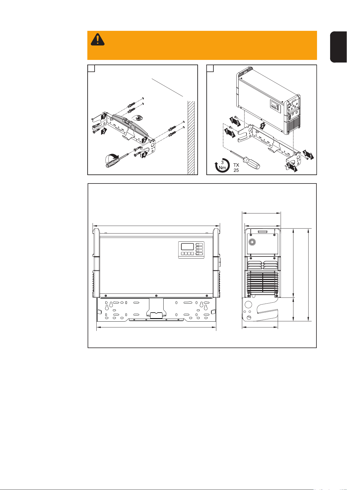
WARNING! Risk of serious damage or injury from articles being dropped or falling over.
- Ensure that all screw connections are secure
- Must only be used with a Fronius Selectiva 8/16 kW charger
1 2
1
8 kW
EN
2
633 mm (24.92 in.)
595,5 mm (23.45 in.)
193 mm (7.60 in.)
180 mm
(7.09 in.)
179 mm (7.05 in.)
344 mm (13.54 in.)
462 mm (18.19 in.)
118 m m
(4.646 in.)
13
Page 16
647 mm (25.47 in.)
16 kW
267 mm (10.51 in.)
247 mm
(9.72 in.)
392 mm (15.43 in.)
508 mm (20 in.)
116 m m
(4.57 in.)
585 mm (23.03 in.)
8.5 mm
(.33 in.)
25 mm (.98 in.)
60 mm
(2.36 in.)
76 mm (2.99 in.)
6 mm
(.24 in.)
7 mm (.28 in.)
Drilling template
Weight of wall bracket:
8 kW 2.7 kg (5.95 lb.)
16 kW 3.15 kg (6.49 lb.)
492 mm (19.37 in.)
400 mm (15.75 in.)
200 mm (7.87 in.)
342 mm (13.46 in.)
494 mm (19.45 in.)
241 mm (9.49 in.)
500 mm (19.69 in.)
450 mm (17.72 in.)
300 mm (11.81 in.)
20 mm (.79 in.)
418 mm (16.46 in.)
6 mm
(.24 in.)
8.3 mm
(.79 in.)
14
Page 17
Control elements and connections
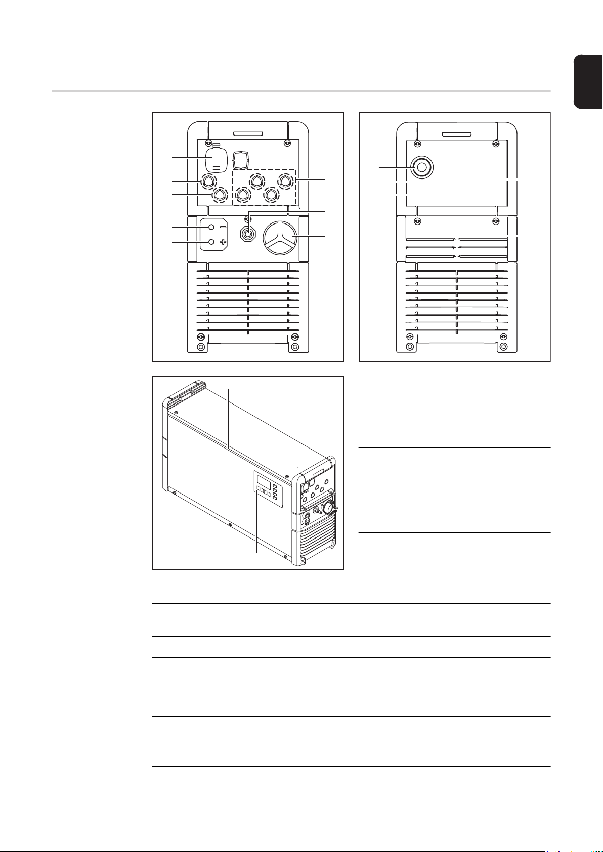
Control elements
and connections
EN
(7)
(6)
(5)
(4)
(3)
(11)
(9)
(8)
(1)
(2)
No. Function
(1) Position for internal electrolyte
circulation option
Compressed air output
(2) Position for internal electrolyte
circulation option
Air intake with air filter (12)
(3) (+) Charger lead
(4) (-) Charger lead
(10)
No. Function
(5) Position for external start/stop option or temperature-controlled charging
option
(6) Position for the remote control system or 12 V indicator lamp options
(7) USB port
The USB port allows a USB stick to be used to update the device and also to log
the charging parameters while charging is in progress. The maximum supply current is 0.5 A.
(8) Positions for relay-related options
(e.g. Aquamatic)
More information can be found in the "Options" section
(9) Mains cable
15
Page 18
Control panel
(10) Control panel
(11) Optional LED strip
lights up in different colours depending on the state of charge. Same as the indicators explained in the "Control panel" section.
(1) (8)
(7)
(6)
(5)
(4)(3)(2)
No. Function
(1) Display
Displays the current charging parameters
Displays settings
(2) "Menu" key
Selects the desired menu
(3) Up/down keys
Select the desired menu item
Set the desired value
(4) Stop/Start key
For interrupting and resuming the charging process
Confirms a menu item or setting
(5) "Battery cooled down" indicator (blue)
Indicates that a battery has cooled down and is ready for use
On steady: After charging has finished, the set cooling time or optionally the battery
temperature has been reached.
Flashes every second: The water refill indicator has also tripped.
More information can be found under "Additional functions" in the "Display" section.
16
Page 19

(6) "Fault" indicator (red)
On steady: Charger faulty. While the red indicator is on, charging cannot take place
(charging interrupted). The relevant status code appears in the display.
Flashes briefly every 3 seconds: The charger outputs a warning. Charging continues. The relevant warning number and the state of charge appear alternately on
the display.
(7) "Charge" indicator (orange)
Lit: during charging
Flashes: if charging has been interrupted
(8) "Battery charged" indicator (green)
On steady: Charging ended
Flashes every second: Charging ended. Water refill indicator has tripped.
EN
17
Page 20
Charging the battery
Charging
WARNING! Danger of serious injury or damage from battery acid escaping or ex-
plosion if faulty batteries are charged. Before charging, ensure that the battery to
be charged is fully functional.
NOTE! The device may be damaged if the charging plug contacts are very dirty.
The resulting increase in contact resistance can lead to overheating and subsequent destruction of the charging plug. Keep the charging plug contacts free from
impurities and clean them if necessary.
Plug the charger into the electrical mains supply.
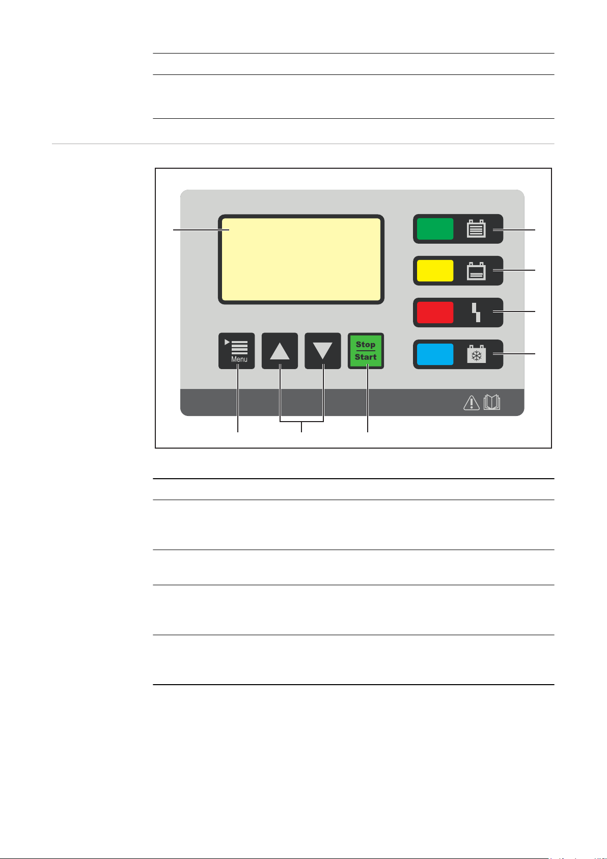
1
The display appears in standard mode. The
monitor displays the charging parameters:
- Type of battery (e.g. wet)
- Charging characteristic (e.g. IUI)
- Battery voltage (e.g. 48 V)
- Capacity (e.g. 300 Ah)
- Day of the week, date and time
The charging parameters can be set individually. For more information, see "Configuration
mode" in the "Display" section.
Connect (+) charger lead to positive pole on battery or connect charging plug
2
Connect (-) charger lead to negative pole on battery or connect charging plug
3
The charger detects that the battery is connected and starts charging. If start-up delay is
activated, then charging will start at the end of the set delay time. For more information,
see "Configuration mode" in the "Display" section.
During the charging process the display shows the following values:
- Current charging current (A)
- Current charging voltage (V)
- The charge already input (Ah)
- Battery temperature with the "temperature-controlled charging" option
- The time (hh:mm) since charging started
The battery symbol indicates the current state of charge. The greater the number of bars
that are displayed, the further advanced the charging process is. As soon as the battery is
fully charged, a minute counter will appear (see figure on right). This counts the minutes
since the end of charging; when a number of chargers are being used, this makes it easier
to decide which battery will have already cooled down most.
18
Page 21

If, however, the standard display is still to be shown rather than the minute counter:
use the "Up/Down" keys to toggle between minute counter and
1
standard display
When the battery is fully charged all 4 bars of the battery symbol appear black. As soon as
the battery is fully charged, the charger begins conservation charging.
- All bars are displayed
- The battery is 100% charged
- The battery is always ready to use
- The battery can remain connected to the charger for as long as required
- Conservation charging counteracts battery self discharge
EN
Interrupting
charging
Stopping charging
To interrupt the charging process:
Press the "Stop/Start" key
1
To resume the charging process:
Press the "Stop/Start" key again
2
As long as a battery is connected to the charger, only the charging process can be interrupted and resumed using the "Stop / Start" key. Display modes can be changed using the
"Menu" key as described in the "Display" section, but this is only possible when there is no
battery connected to the charger.
WARNING! Danger of serious injury or damage from ignition of oxyhydrogen
through sparks generated when the charger leads are disconnected. Before disconnecting or unplugging the charging plug, first stop the charging process by
pressing the "Stop / Start" key.
To stop the charging process:
Press the "Stop/Start" key
1
Disconnect (-) charger lead from negative pole on battery or unplug charging plug
2
Disconnect (+) charger lead from positive pole on battery or unplug charging plug
3
Unplug the charger's mains plug from the electrical mains supply
4
19
Page 22

Display
Overview of
modes
The device has the following modes:
Standard mode
In standard mode the display shows the charging parameters
Statistics mode
Visualises the frequency of the device operating modes and shows the total
number of charging actions. Also shows an overview of the total and average Ah
produced and energy consumed per charge
History mode
Provides information about the parameters for all the stored charging processes
Configuration mode
Configuration mode enables all the settings for the device and the charging process to be adjusted
USB mode
USB mode enables a device to be updated, device configurations to be saved
and loaded, and the charging parameters to be recorded during the charging
process - all using a USB stick
As long as a battery is connected to the battery charging system, the charging process can
only be interrupted and resumed using the "Stop/Start" key. Display modes can be
changed using the "Menu" key as described in the following sections that explain the individual modes, but this is only possible when there is no battery connected to the battery
charging system.
Standard mode Once the mains plug has been connected to the public grid, the display will automatically
operate in standard mode.
In standard mode the display shows the
charging parameters:
- Type of battery (e.g. wet)
- Charging characteristic (e.g. IUI)
- Battery voltage (e.g. 48 V)
- Capacity (e.g. 300 Ah)
- Day of the week, date and time
The charging parameters can be set individually. More information can be found in the
"Configuration mode" section.
Menu selection
Change from standard mode to the menu
selection as follows:
Press and hold the "Menu"
1
key for approx. 5 seconds
20
Page 23
Change from all other modes to the menu selection as follows:
Press the "Menu" key briefly
1
To select the desired mode:
Use the "Up/Down" keys to select the symbol for the desired mode
2
- e.g. the battery symbol for standard mode
Use the "Stop/Start" key to confirm the "Tick" symbol
3
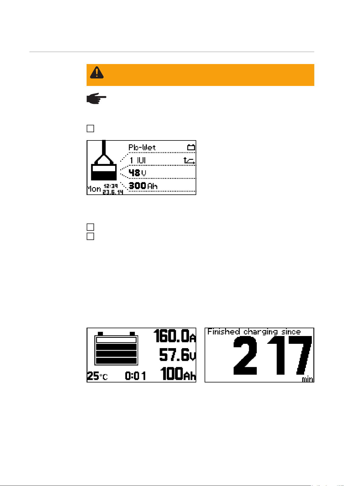
Statistics mode In statistics mode, horizontal bars display
the frequency of the following device operating statuses:
- Idle
- Charging
- Conservation charge
- Cooldown
- Error
EN
Use the "Up/Down" keys to toggle between page 1/2 and page 2/2
1
Page 2/2 shows the following values:
- Total number of charges
- Total Ah output
- Average Ah output per charge
- Total energy consumed (kWh)
- Average energy consumed (kWh) per
charge
The consumed energy display is a standard value and can deviate by up to 5% from the
actual amount of energy. At lower power levels the deviation may be higher.
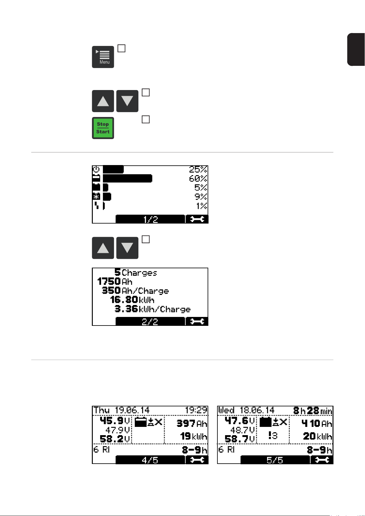
History mode History mode provides information about the parameters for all the stored charging pro-
cesses. In order to show changing or different displays, two versions of the display window
are shown below:
21
Page 24

Use the "Up/Down" keys to scroll between the pages for each
1
stored charging process
Text content of the display window:
- Start date of charge, e.g. Thursday 19.06.14
- Start time of charge, e.g. 19:29 or charging period, e.g. 8 h 28 min
- Voltage at charge start, e.g. 45.9 V
- Voltage after 5 minutes, e.g. 47.9 V
- Voltage at charge end, e.g. 58.2 V
- Input Ah, e.g. 397 Ah
- Input kWh, e.g. 19 kWh
- Charging characteristic, e.g. 6 RI
- Set charging period, e.g. 8-9 h or set Ah, e.g. 400 Ah or set charge end time (not
shown)
Symbols shown:
- Full battery:
charging has been completed
- Empty battery:
charging has not been completed
- Exclamation mark with number:
Error or warning has been output with the corresponding status code. More information can be found in the "Status codes" section.
- Key symbol with a tick:
charging was stopped properly using the "Stop/Start" key
- Key symbol with a cross:
charging was stopped without using the "Stop/Start" key
Configuration
mode
Configuration mode provides the following setting options:
- "Charging settings": settings for the battery
- Type of battery, e.g. "Wet"
- Charging characteristic, e.g. "IU"
- Capacity (Ah) or charging time (h) depending on the charging characteristic
- Cells: voltage (V) and number of battery cells or automatic setting of the number
of cells
CAUTION! Risk of damage to the battery. The number of cells should
only be set automatically for batteries with 24 V, 48 V and 80 V nominal
voltage. Do not set the number of cells automatically for deep discharged batteries.
- "Additional functions":
for individual adaptation options for the charging characteristic
- "General options": general settings
- Language
- Contrast
- Time (hh:mm:ss)
- Date (dd:mm:yy)
- Length of charger lead (m)
- Charger lead cross section (mm2)
- Code for accessing the configuration menu activated/deactivated
- Time interval for the parameter(s) recorded on the USB stick
- "Reset Settings": resets settings to those when the charger left the factory or optionally
to Fronius defaults
- includes an ("OK?") double-check prompt for reconfirmation
22
Page 25

First the screen will appear in its initial format, showing the date and time.
The "Up/Down" keys can be used to retrieve the following informa-
1
tion:
- Serial number of the charger plus serial number and version
of the configuration memory
- Hardware control: hardware version and serial number
- Primary power module: hardware version and serial number
- Software: main software, secondary software, primary soft-
ware
The procedure for opening the configuration menu is as follows:
Press the "Stop/Start" key
1
EN
You will be prompted to enter a code:
The code required is "1511", and is entered as follows:
Using the "Up/Down" keys, enter the first digit of the code
1
Press the "Menu" key to move to the next digit of the code
2
Continue to follow the procedure described above until the com-
3
plete code has been entered
Use the "Stop/Start" key to confirm the code entered
4
23
Page 26

You will now be prompted to select one of the main menu items for the configuration
mode:
When you select a menu item you may be
presented with a symbol prompting you to
read the operating instructions. Confirm
this prompt by pressing the "Stop/Start"
key again.
The procedure for navigating the configuration menu and its submenus is as follows:
Use the "Up/Down" keys to select the desired menu item
1
Use the "Stop/Start" key to confirm the menu item, and reconfirm
2
any double-check prompt (e.g. "OK?")
Use the "Up/Down" keys as necessary to choose an item e.g. "Off/
3
On" or enter a value
Use the "Stop/Start" key to confirm what you have entered
4
If the cursor should move to another setting or position after con-
5
firmation of the previous setting, then the procedure described in
points (3) and (4) should be repeated
To exit the current menu:
Press the "Menu" key to return to the higher-level menu
6
24
Page 27

For an example, see the explanation below of how to set the charging parameters:
Use the "Up/Down" keys to select the "Charging settings" menu
1
item
Use the "Stop/Start" key to confirm this menu item
2
The choice of settings for the "Charging settings" menu item will now be displayed:
EN
the display may vary depending on the selection made. If the "Pb-Wet" type of battery has
been selected in combination with the "RI" characteristic ("Curve") as in the example here,
then the title "Ah" is replaced by the "Charging time" and "Charge end" settings.
When applying the settings, the user will be guided through the menu in much the same
way as a wizard function.
Use the "Up/Down" keys to select the desired parameter (e.g.
3
"Cells")
Use the "Stop/Start" key to confirm the parameter
4
Use the "Up/Down" keys to set the desired value (e.g. "24" for the
5
number of battery cells)
Use the "Stop/Start" key to confirm what you have entered
6
-> Settings Below is a detailed description of the "-> Settings" menu item for the "Charging settings"
menu item discussed above. Navigation is performed as described in the "Configuration
mode" section.
25
Page 28

A list appears with the following selection options:
The individual selection options are explained in greater detail below:
Electrolyte circulation ("Air Pump"):
The following settings are available for electrolyte circulation:
- Off:
- Electrolyte circulation switched off
- Continuous:
- Electrolyte circulation permanently on
- Program 1 to 5:
- Default electrolyte circulation programs
- More information on the programs can be found under "Electrolyte circulation" in
the "Options" section
- Automatic:
- Automatic adjustment of the electrolyte circulation as dictated by the situation
- "User" - "On"/"Off":
- Individual setting of the electrolyte circulation
- The settings for "On" and "Off" determine the pulse/pause ratio of the air flow intervals
Temperature-controlled charging:
26
The following settings are available for temperature-controlled charging:
- automatic/OFF/required:
- automatic ... Temperature-dependent adjustment of the charging characteristic
- OFF ... The measured battery temperature is not taken into account
- required ...
Charging only starts when a temperature sensor is connected
Page 29

- Error overtemperature ON/OFF:
- ON ... Error message in the event of battery overtemperature
Charging process stops and can only be continued once the battery has cooled
down and been reconnected
- OFF ... No error message in the event of battery overtemperature
- Warning overtemperature ON/OFF:
- ON ... Warning in the event of battery overtemperature
- OFF ... No battery overtemperature warning
Equalize charge:
- ON:
If the battery remains connected to the battery charging system for the duration of the
"equalize charge delay", then a special type of charging takes place. This prevents
acid stratification.
- OFF:
There is no equalising charge.
Delay:
Charge start delay:
Delay time (minutes) of actual start of charging relative to the moment when charge start
was initiated
Charge end delay:
Delay time (minutes) before charge end is signalled (e.g. green indicator) relative to the
moment when charging actually stopped
EN
At mains failure restart charging:
If this option is chosen, the charging process is restarted automatically as soon as the
mains supply becomes available again after a disruption to the electrical mains supply.
Calendar:
The calendar function allows charging to be started automatically according to the following criteria:
- Time window in which charging may not be started if a battery is connected
- Time window in which charging is to be started using a defined characteristic 1 if a battery is connected
- Time window in which charging is to be started using a defined characteristic 2 if a battery is connected
To activate the calendar function,
1
select the setting "ON" and confirm
Definition of characteristic 1:
- Type of battery
e.g. Pb-Wet
- Characteristic:
e.g. RI
- Additional settings, depending on the
characteristic:
e.g. Charging time 7-8 h
27
Page 30

Definition of characteristic 2:
- Characteristic:
e.g. RI
- Additional settings, depending on the
characteristic:
e.g. Charging time 7-8 h
Day Setting 1-3:
The day settings allow up to 3 different
charging start time profiles to be defined
with the following settings:
- Symbol for characteristic 1:
Time window in which charging is to be
started using characteristic 1 (e.g.
0:00-7:00)
- Stop:
Time window in which charging must
not take place (e.g. 7:00-16:00)
- Symbol for characteristic 2:
Time window in which charging is to be
started using characteristic 2 (e.g.
16:00-24:00)
NOTE! Ongoing charging operations are unaffected by the set time windows. If in
the example above a battery is connected at 06:45, the charge end time is governed according to need and is not interrupted by the end time specified for the
set time window (7:00 in the example).
If the battery is connected during the "stop" time window, charging is started automatically during the next time window.
If charging is started manually during the "stop" time window, charging will always
take place using characteristic 1.
Additional settings:
- Change the allocated characteristic:
characteristics symbol
- Remove the selected characteristic:
remove
Week Setting:
- The "Day Setting 1-3" list referred to above also has an additional entry available Week Setting
28
Page 31

Special Charges:
A previously created day setting can be assigned to any day of the week.
EN
When the calendar function is active, a calendar symbol (shown here with the number
"4") appears on the display.
Selecting "Special Charges" allows one or
more of the alternative charging types to be
performed temporarily:
- ON: Function activated
- OFF: Function deactivated
The "Repeat" setting defines how often the alternative charging mode should be performed
until the device reverts to the original charging setting again:
- Setting range: 1 to 10 repetitions
Disable Start Button:
- ON:
The charging process cannot be interrupted or terminated using the "Stop/Start" key;
one reason for this is to prevent unauthorised intervention.
- OFF:
The charging process can be interrupted or terminated using the "Stop/Start" key.
Special function Opportunity Charge
One way of increasing the service life of a
battery is to re-charge it during an interval
when it is not in use.
- ON: Function activated
- OFF: Function deactivated
The "Opportunity Charging" function is only available when the battery capacity (Ah) preset
in the "Ah" section matches the capacity of the battery that is actually connected.
- Set the correct value for the capacity of the connected battery in the "Ah" section.
29
Page 32

When opportunity charging is "ON" and a battery is connected, the following appears:
- Figure on left: indication when RI characteristic is selected
- Figure on right: indication for standard characteristics
To start opportunity charging:
- Use the "Up" key to select the runner symbol (1)
(1)
Additional functions
- Figure on left: "Runner symbol" (1)
- Figure on right: indication when opportunity charging starts
A detailed explanation of the menu item "Additional functions" in configuration mode can
be found below. Navigation is performed as described in the "Configuration mode" section.
Select the "Additional functions" menu
1
item
A list appears with the following selection options:
30
The individual selection options are explained in greater detail below:
Setting the "Blue LED" indicator:
Time (minutes) that must be allowed to pass before the blue "battery cooled down" indicator should come on to indicate that a battery has cooled down sufficiently. The time from
the end of charging is used as the setting.
Page 33
In conjunction with the "Temperature-controlled charging" option, a temperature value can
be set here. The blue "battery cooled down" indicator will light up to signal a sufficientlycooled battery once the temperature drops below this value.
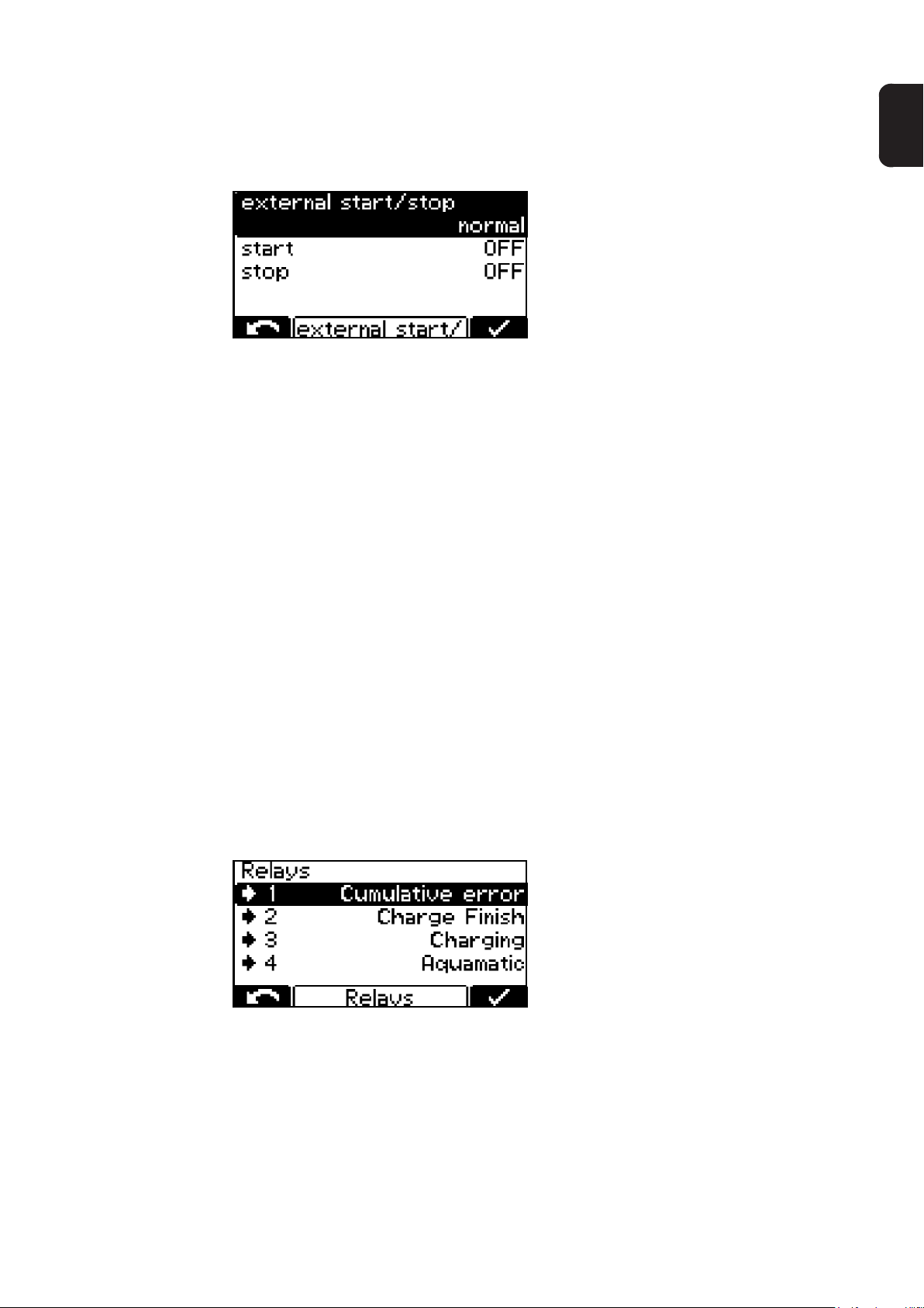
External start/stop:
The following settings are available when external start/stop is selected:
- Start:
normal ON:
- Charging starts when an external switch is closed and a battery is detected
- Or when the charging plug is connected by closing the auxiliary contacts and a
battery is detected
normal OFF:
- Charging starts when a battery is connected
- Stop:
normal ON:
- Charging is interrupted when an external switch is opened
- Or when the charging plug is disconnected by opening the auxiliary contacts
normal OFF:
- Opening of an external switch or the auxiliary contacts is ignored
- Button:
The function of the "Stop/Start" key can be simulated using an external button
EN
Refill Indicator:
The refill indicator is a message that appears as soon as the battery needs topping up with
distilled water. The time at which refilling is deemed necessary can be defined as follows:
- days: number of days that have passed since the message was last output or the option was set
- charge count: number of charges that have been performed since the message was
last output or the option was set
Relays:
31
Page 34

When a relay board has been selected, one of the following functions can be set for each
of the 4 terminals (-> 1) to (-> 4), viewed from left to right:
- Aquamatic
- Signal to activate a solenoid valve, for example
- "Standard" program with preconfigured factory settings
- "User" with user-defined settings
- More information about Aquamatic can be found under "Aquamatic" in the "Op-
tions" section.
- Charging
- Charge 80%
- Charge end
- Main Charge Finished
- Signal to indicate that the main charging phase has finished
- Charge OK
- Battery is being charged or is already fully charged
- Common error:
- Signal in the event of an error
- A power failure can also be displayed as an error if required (setting "ON")
- Freely-defined text, which could for example include the contact details of the
dealer, can be displayed if the device is in an error state. More information can be
found in the "USB mode" section.
- Signal Lamp:
- One or more suitable lamps can be connected to the relay board to indicate the
state of charge or operating status of the charger.
- More information can be found under "Signal lamp" in the "Options" section.
- Immobiliser device
- ON:
- The relay picks up permanently as soon as the charger is connected to the mains.
- Refill Indicator:
- Signals that the battery needs topping up with distilled water.
- More information can be found under "Additional functions" in the "Display" sec-
tion.
- Battery Cold
- "External Air Pump" for electrolyte circulation
- The settings are applied as described under "-> Settings" for the air pump
More information on the relay board can be found in the "Options" section.
External lamp setting:
as described under "Charging Lights" in the "Options" section, suitable signal lamps can
be connected to indicate the state of charge or operating status of the charger. The following settings are available:
- normal (conventional signal lamps)
- RGB (LED strips)
Remote control system:
The contrast for the remote control system can be adjusted.
At mains failure restart charging:
If this option is chosen, the charging process is restarted automatically as soon as the
mains supply becomes available again after a disruption to the electrical mains supply.
32
Page 35
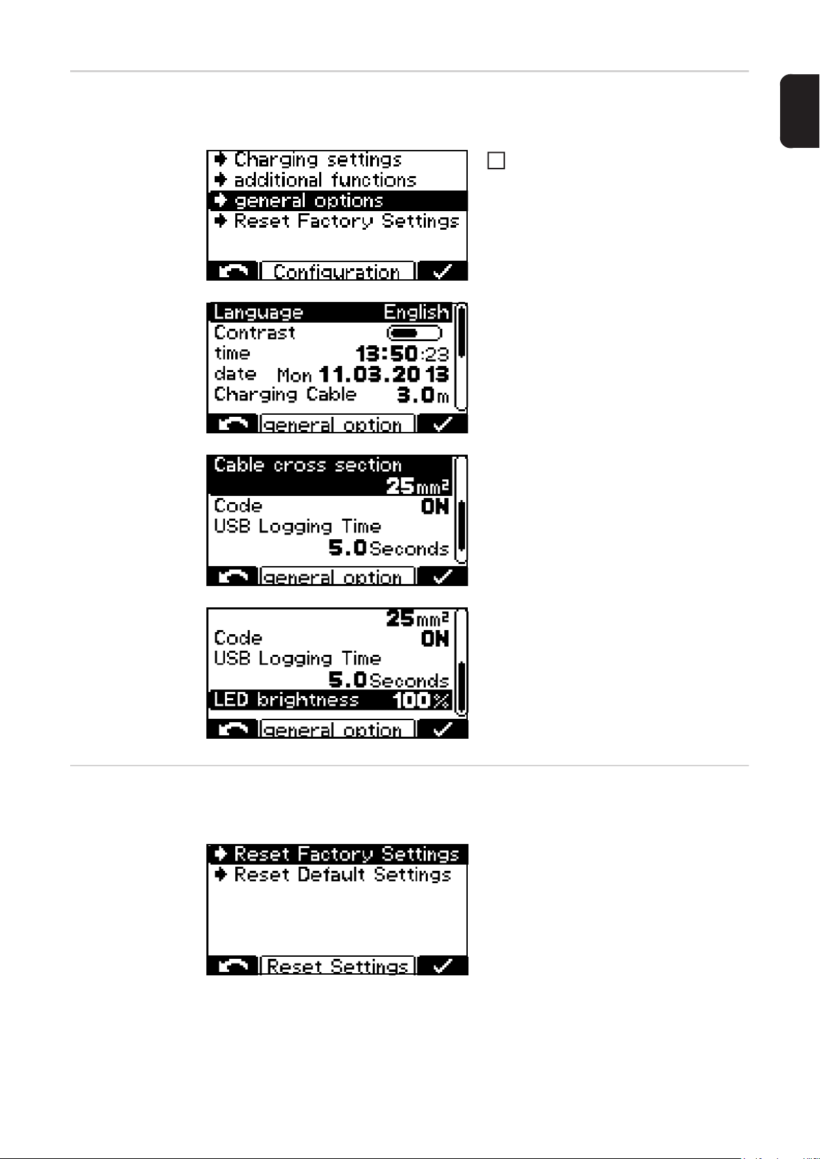
General settings A detailed explanation of the "General options" menu item in configuration mode can be
found below. Navigation is performed as described in the section "Configuration mode".
Select the "General options" menu
1
item
A list appears with the following selection
options:
- Language
- Contrast
- Time
- Date
- Basic length of charging cable (in m)
- Cable cross section (mm²)
- Code entry required / not required to
access configuration mode (Code ON /
OFF)
EN
- Time interval (s) for recording charging
parameters on the USB stick (USB
Logging Time)
- Brightness of the state of charge indicators
Reset settings The menu item below "General options" offers two alternative ways of resetting all the set-
tings:
Reset Factory Settings:
- Resets to factory settings
Reset Default Settings:
- Resets settings to Fronius defaults
33
Page 36

USB mode
In USB mode, the display shows whether or
not a USB stick is connected.
The USB stick must conform to the following specifications:
- Formatting: FAT32
- 32 Gigabyte maximum
Use the "Stop/Start" key to access the following settings
1
Use the "Up/Down" keys to scroll between the settings
2
Use the "Stop/Start" key to confirm the desired setting
3
- Safely remove
Safely remove the USB stick
- Update
A list of the suitable update files stored on the USB stick opens
Select and confirm the desired file in the same way as scrolling through the settings
Do not change the automatically assigned file names of the update file.
- Save datalogger
The data relating to the logged charging parameters stored on the device is saved to
the USB stick as ".csv" files
Automatic folder structure: *
Fronius\<Geräte-Seriennummer>\Charges\<yyyymmdd>\<hhmmss.csv>
- Save events
Aids troubleshooting by service personnel
- Save configuration
Saves the current device configuration to the USB stick
34
Page 37

Status codes
- Load configuration
Loads onto the device one of the suitable device configurations stored on the USB
stick
- Load dealer text
A text file can be loaded from the USB stick that is displayed as soon as the device
enters an error state. The text file can, for example, contain the contact details of the
dealer. The file must be saved on the USB stick as a ".txt" file in "unicode" format. The
file name must be "dealer.txt". The number of characters is restricted to 99.
* If a USB stick is connected while charging is in progress, the csv files are saved di-
rectly to the USB stick. The folder structure here is also created automatically and
differs due to the presence of the "Datalog" folder instead of the "Charges" folder.
EN
If a fault occurs during operation, specific status codes may be displayed. Faults can result
from the following:
- Battery is connected with reverse polarity
- The voltage of the connected battery is unsuitable
- The device has overheated
- There is a software or hardware fault
If an error message appears on the display and if you cannot resolve the error yourself:
Note the displayed status code: e.g. "Statecode (31)"
1
Note the configuration of the device
2
Contact After-Sales Service
3
Freely-defined text, which could for example include the contact details of the dealer,
can be displayed if the device is in an error state. More information can be found in the
"USB mode" section.
Status codes caused by external factors
Number Cause
(11) Mains undervoltage or overvoltage
(12) Phase failure (device continues charging with reduced power)
(13) External temperature sensor faulty
(14) Electrolyte circulation faulty (pressure switch not switching)
Status codes in the event of a battery fault
Number Cause
(22) Battery undervoltage
(23) Battery overvoltage
(24) Battery too hot (with external temperature sensor only)
(25) Battery undertemperature (with external temperature sensor only)
(26) Cell fault detected
35
Page 38

Status codes in the event of a charging fault
Number Cause
(31) Time exceed in I1 phase
(32) Time exceed in U1 phase
(34) Ah exceed
(35) Time exceed in I2 phase
(36) Set voltage not reached in I2 phase (format characteristic only)
(37) Problem with RI charge
(38) Set charging time cannot be reached
Status codes in the event of a fault in the primary circuit
Number Cause
(500) Module 1 (top) temperature sensor faulty
(501) Module 2 (bottom) temperature sensor faulty
(502) PCB temperature sensor faulty
(503) Primary overtemperature
(504) Fan jammed/faulty
(505) Intermediate circuit over/undervoltage
(506) Intermediate circuit imbalance
(507) Primary supply voltage outside the tolerance
(508) Power failure
(509) Wrong device configuration
(510) Primary EEPROM faulty
Status codes in the event of a fault in the secondary circuit
Number Cause
(520) Secondary temperature sensor faulty
(521) Secondary overtemperature
(522) Output fuse faulty
(523) Secondary supply voltage outside the tolerance
(524) Secondary reference voltage outside the tolerance
(525) Current offset
(526) Current offset outside the tolerance
(527) Power module overcurrent (primary)
(529) No secondary communication
(530) No primary communication
(531) Secondary EEPROM faulty
(532) μC fault
Status codes in the event of a fault in the controller
Number Cause
(540) CFM missing/faulty
(541) No secondary communication
(542) Secondary initialisation failed
(543) Program/memory fault in characteristic control
(544) Program/memory fault in characteristic control
36
Page 39

Status codes in the event of a fault in the controller
Number Cause
(545) Primary initialisation failed
(546) Update failed
(547) Load/save settings failed
(548) Load/save characteristic settings failed
(549) Charging could not be resumed after a power failure
(550) Time not set
(551) Hardware change detected
(552) CFM invalid
EN
37
Page 40
Options
Safety In order to connect optional components it may be necessary to open the housing. The fol-
lowing warning notices must be obeyed:
WARNING! An electric shock can be fatal. The housing may only be opened by
a service engineer who has been trained by the manufacturer. The device must
be disconnected from the mains before starting any work with the housing
opened. A suitable measuring instrument must be used to ensure that electricallycharged components (e.g. capacitors) are fully discharged. Use an easily legible
and understandable warning sign to ensure that the charger is not reconnected
to the mains supply before all the work has been completed.
WARNING! Work that is carried out improperly can cause serious injury or damage. All work involved with connecting optional components must only be carried
out by qualified specialist technicians. If there are installation instructions or a
leaflet for the optional component concerned, then all warning notices and instructions therein must be obeyed.
Electrolyte circulation
The electrolyte circulation option features an air pump integrated in the battery charging
system. This introduces air into the battery through capillary tubes that are provided specifically for this purpose. This allows intensive mixing of the electrolyte to take place. The
benefit is reduced heating of the battery, and consequently longer battery-life, plus reduced
water loss during charging.
NOTE! Risk of damage to air pump from the ingress of electrolyte from the battery
or from operation without any back pressure. Always set up the battery charging
system at least 0.5 m (1 ft. 7.69 in.) above the battery to be charged. Always use
an undamaged, purpose-supplied connecting hose to connect the compressed
air outlet on the battery charging system to the battery.
If a pump fault or leaks in the connection with the battery result in a fault being detected,
then the status code "Statecode 14" will appear on the display. One way in which this fault
can be indicated is by using an external indicator lamp to show a common error.
The electrolyte circulation cycle is controlled by the battery charging system's control system. A number of selection options are available for this purpose in the configuration menu.
More information can be found under "Additional functions" in the "Display" section.
The default preconfigured programs 1 to 5 are among these selection options. The relevant
parameters for these programs are listed in the table below together with a subsequent explanation.
38
Program ON 1 OFF 1 Repeat ON 2 OFF 2
1 30 min 25 min 1 x 5 min 25 min
2 3 min 10 min 4 x 3 min 20 min
3 3 min 12 min 1 x 3 min 12 min
4 5 min 10 min 3 x 5 min 20 min
5 2.5 min 7.5 min 1 x 2.5 min 7.5 min
In each of these programs, the solenoid valve opens for a time "ON 1" and closes for a time
"OFF 1". This process is repeated for the number of times specified under "Repeat". After
this number of repetitions has been completed, the process continues with the "ON 2" and
"OFF 2" times until charging is completed.
Page 41
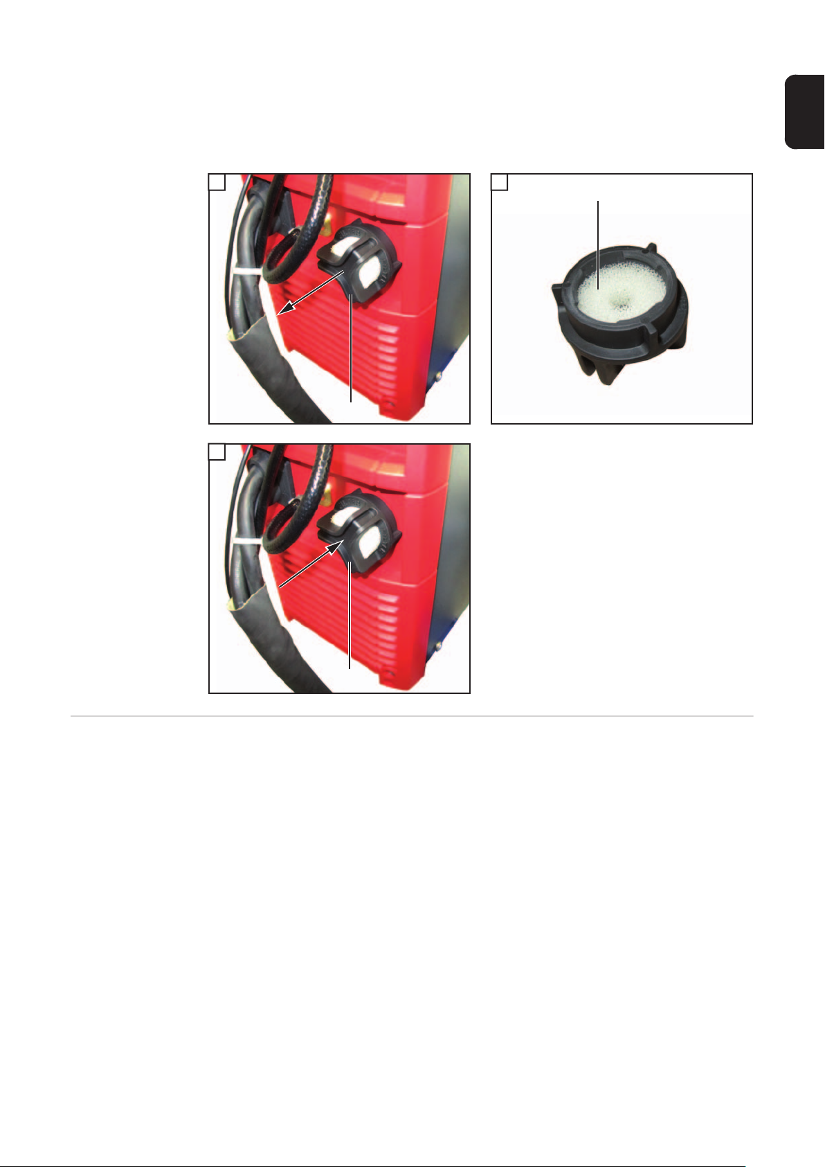
Cleaning the air filter insert
The air filter insert for the integrated air pump should be cleaned once a year. In dusty environments the cleaning interval should be shortened accordingly. The air filter insert (2)
must be removed for cleaning. Remove the air filter (1) by pulling it out and then refit it as
follows:
1 2
1
2
(2)
(1)
1
3
EN
External start/
stop
(1)
The external start/stop option prevents sparking if the charging plug is disconnected during
charging. Dedicated auxiliary contacts inside the plug detect the removal of a shorting
jumper in the counterpart before the main contacts have even become separated. This triggers an immediate stop to charging. As a result there is no wear to the main contacts, and
this arrangement safeguards more effectively against an oxyhydrogen explosion.
39
Page 42

Charging lights
(1)
(2)
(3)
(4)
(5)
(+)
(-)
RCS 3.0 Lights
1
12V
2
GREEN
3
YELLOW
4
RED
BLUE
Temp. Sensor
+/-
Ext. Start/Stop
WARNING
Hazardous Voltage
Kondensator Entladezeit < 2 min.
Capacitor discharge time < 2 min.
Décharge de condensateur < 2 min.
Suitable signal lamps can be connected to the connections inside the device as illustrated
in order to indicate the state of charge or operating status of the charger. Each signal lamp
must have a working voltage of 12 V, and the total current drawn by all the lamps must not
exceed 0.5 A. Connections (1) to (5) in the Figure are assigned as shown below. It is advisable to use the lamp colours shown below:
Connection Function Colour
(1) 12 V power supply
(2) Battery is fully charged green
(3) On: battery being charged
yellow
Flashing: charging has been interrupted
(4) An error has occurred (common error) red
(5) The battery has already cooled down and is ready for use blue
If the RGB setting (LED strip) is set in the menu, then connection 3 (YELLOW) is not supported. The normal setting (conventional signal lamp) or RGB (LED strip) for the "External
Lamp" function is explained under "Additional functions" in the "Display" section.
Temperature-controlled charging
The temperature-controlled charging option always adjusts the charging voltage according
to the current temperature of the battery. This results in considerably longer battery-life, especially where batteries are used in cold stores.
Relay board The optional relay board enables the charger's operating status and the connected bat-
tery's state of charge to be evaluated externally. One or more external consumers can also
be supplied with 230 V AC. A neutral conductor in the electrical mains supply is a prerequisite for this. The configuration of the relay board outputs is explained in the operating instructions for the battery charging system: "Additional functions" in the "Display" section.
More information on the relay board can be found in the instructions supplied with the relay
board option.
40
Page 43

There follows an overview of the options that are directly connected with the relay board.
These relay-connected options are activated through the relay board outputs:
- Aquamatic
- Charging
- Charge 80%
- Charge end
- Main charge finished
- Charge OK
- Common error
- Signal lamp
- Immobiliser device
-ON
- Refill indicator
- Battery cooled
- External air pump (electrolyte circulation)
Aquamatic The Aquamatic contains the controller for a solenoid valve that automatically tops up the
water in the battery to be charged.
- Standard setting:
- At the start of the recharging phase, the solenoid valve opens for 12 seconds and
then closes for 6 seconds
- This cycle is repeated 26 times
- USER setting:
- Configurable "ON" time (solenoid valve opens) after the end of the main charge
phase
EN
Charging The "Charging" option is suitable for actuating a signal lamp for instance. While charging
is in progress, the corresponding relay picks up automatically.
Charge 80% Like the "Main charge finished" function, the relevant relay switches as soon as the battery
is 80% charged.
Charge finish The "Charge finish" option is suitable for actuating a signal lamp for instance. Once the
configured charging characteristic is fully completed, the corresponding relay picks up automatically.
Main charge finished
Common error
message
The "Main charge finished" option is suitable for actuating a signal lamp for instance. When
the main charge phase finishes, the corresponding relay picks up automatically.
The "Common error message" option is suitable for actuating a signal lamp for instance.
Each time an error is detected, the relevant relay picks up automatically.
Signal lamp As an alternative to the charging lights, one or more suitable lamps can be connected to
the relay board to indicate the state of charge or operating status of the charger. These
lamps can be designed for a voltage of up to 30 V DC or up to 250 V AC on a starpointearthed network.
41
Page 44

If the lamp circuit is potential-free, then the switching current must not exceed 4 A. A lamp
that is actuated by the 230 V supply relay must be operated with an output current of max.
1 A.
Immobiliser If the charger is built into the vehicle as an on-board device, then the optional immobiliser
will prevent the vehicle from being started unintentionally whilst charging is taking place.
This protects the vehicle, the battery and the charger leads from damage.
As soon as the vehicle is connected up to the mains supply, the corresponding relay picks
up and blocks the ignition signal for instance. Another example is the actuation of a suitable
signal lamp to convey the message visually that charging is currently in progress.
Battery cooled
down
External air pump
- electrolyte circulation
LED strip The LED strip acts as a status indicator and lights up in the same colours as the display
Floor bracket The robust floor bracket ensures safe fitting on site. More information can be found in the
Wall bracket The robust wall bracket ensures safe fitting on site. More information can be found in the
The corresponding relay switches automatically once the time set in the menu has passed.
This option enables an external air pump to be activated by a relay contact in the sense of
the "electrolyte circulation" option.
elements on the control panel. An LED strip including a diffuser is installed in the gap between the front wall and upper part of the housing.
corresponding fitting instructions.
corresponding fitting instructions.
"Mobile" kit A carrying strap and handle improve the mobility of the device.
RCS 3.0 remote
indication
42
The remote indication allows the device to be fully controlled from a distance of up to 30 m
(98 ft., 5.1 in.). This option includes a full control panel in an aluminium housing that provides IP42 protection.
Page 45

Technical data
EN
Selectiva 8 kW
WARNING! An electric shock due to a fault current can be fatal. Nothing other
than a type B residual current circuit breaker should ever be used for connecting
the device to the mains.
Mains voltage (-10% / +15%) *
Optional:
Mains fuse protection ** 16 A
Minimum mains cable cross section 2.5 mm² (0.003875 in²)
Duty cycle 100%
EMC device class B
Protection class Protection class 1
Degree of protection *** IP 20
Overvoltage category III
Operating temperature **** -20 °C to +40 °C
Storage temperature -25 °C to +80 °C
Relative humidity maximum 85%
Maximum altitude above sea level 2000 m (6561 ft.)
Mark of conformity according to rating plate
Product standard EN62477-1
Dimensions l x w x h 633 x 180 x 344 mm
Weight (with standard mains cable and charger
lead)
Pollution level 3
3~ NPE 400 / 230 V / 50/60 Hz
3~ PE 400 / 230 V / 50/60 Hz
(-4 °F to 104 °F)
(-13 °F to 176 °F)
(24.92 x 7.09 x 13.54 in.)
23 kg (50.71 lb.)
*) The device is approved for operation on neutral-earthed mains networks with a
maximum outer conductor nominal voltage of 400 V.
**) If the charger is protected by a 32 A fuse, the thermal stress of the automatic circuit
breaker must not exceed 82000 A²s.
The earth leakage current is less than 3.5 mA.
***) For indoor use only, do not expose to rain or snow
****) A high ambient temperature may result in a power reduction (derating)
Cable lengths must not exceed 30 m (98 ft. 5.1 in.).
Device-specific data
Device Max. AC cur-
rent
Selectiva 2100 11 A 3900 W 24 V 100 A
Selectiva 2120 12.5 A 4600 W 24 V 120 A
Selectiva 2140 14.5 A 5400 W 24 V 140 A
Selectiva 2160 10 A 6100 W 24 V 160 A
Selectiva 2180 11 A 6800 W 24 V 180 A
Selectiva 2200 11 A 6900 W 24 V 200 A
Max. AC power Charging volt-
age
Charging current
43
Page 46

Device-specific data
Device Max. AC cur-
rent
Selectiva 4060 12.5 A 4600 W 48 V 60 A
Selectiva 4075 15 A 5700 W 48 V 75 A
Selectiva 4090 11 A 6800 W 48 V 90 A
Selectiva 4120 14 A 8800 W 48 V 120 A
Selectiva 4140 15 A 9500 W 48 V 140 A
Selectiva 4160 15.5 A 9600 W 48 V 160 A
Selectiva 8040 8.5 A 5000 W 80 V 40 A
Selectiva 8060 12 A 7500 W 80 V 60 A
Selectiva 8075 14.5 A 9100 W 80 V 75 A
Selectiva 8090 14.5 A 9200 W 80 V 90 A
Max. AC power Charging volt-
age
Charging current
Selectiva 16 kW
WARNING! An electric shock due to a fault current can be fatal. Nothing other
than a type B residual current circuit breaker should ever be used for connecting
the device to the mains.
Mains voltage (-10% / +15%) *
Optional:
Mains fuse protection ** 32 A
Minimum mains cable cross section
Selectiva 8120 / 8140
Selectiva 8160 / 8180
Duty cycle 100%
EMC device class B
Protection class Protection class 1
Degree of protection *** IP 20
Overvoltage category III
Operating temperature **** -20 °C to +40 °C
Storage temperature -25 °C to +80 °C
Relative humidity maximum 85%
Maximum altitude above sea level 2000 m (6561 ft.)
Mark of conformity according to rating plate
Product standard EN62477-1
Dimensions l x w x h 647 x 247 x 392 mm
Weight (with standard mains cable and charger
lead)
Pollution level 3
3~ NPE 400 / 230 V / 50/60 Hz
3~ PE 400 / 230 V / 50/60 Hz
4 mm² (0.0062 in²)
6 mm² (0.0093 in²)
(-4 °F to 104 °F)
(-13 °F to 176 °F)
(25.47 x 9.72 x 15.43 in.)
34 kg (74.96 lb.)
44
*) The device is approved for operation on neutral-earthed mains networks with a
maximum outer conductor nominal voltage of 400 V.
**) The earth leakage current is less than 3.5 mA.
***) For indoor use only, do not expose to rain or snow
****) A high ambient temperature may result in a power reduction (derating)
Page 47

Cable lengths must not exceed 30 m (98 ft. 5.1 in.).
Device-specific data
Device Max. AC
current
Max. AC
power
Charging voltage
Charging
current
Z
max
Selectiva 8120 24.5 A 14800 W 80 V 120 A 96 mOhm
Selectiva 8140 28 A 17200 W 80 V 140 A 82 mOhm
Selectiva 8160 29.5 A 18200 W 80 V 160 A 74 mOhm
Selectiva 8180 29.5 A 18300 W 80 V 180 A 67 mOhm
EN
45
Page 48

Fronius Worldwide - www.fronius.com/addresses
Fronius International GmbH
Froniusplatz 1
A-4600 Wels
E-Mail: perfect.charging@fronius.com
http://www.fronius.com
Under http://www.fronius.com/addresses you will find all addresses of our sales branches and partner firms!
 Loading...