

Fronius Selectiva 4.0 UL B1 (2kW), Selectiva 4.0 UL C1 (3kW) Operating Instruction [en, es]
Page 1

Operating
Instructions
Selectiva 4.0 UL
B1 (2kW), C1 (3kW)
EN-US
ES
FR
DE
Operating instructions
Manual de instrucciones
Instructions de service
Bedienungsanleitung
42,0410,2909 001-27042023
Page 2

Page 3

Table of contents
Power categories 5
General 5
Safety Instructions 6
General 6
Explanation of Safety Instructions 6
Environmental conditions 7
Mains connection 7
Dangers due to grid and charging current 7
Danger due to acids, gases, and vapors 7
General information on working with batteries 8
General note on the use/maintenance of charging plug connections and contacts 8
Personal protection and protection of others 8
Safety measures in normal operation 9
EMC device classifications 9
EMC Measures 9
Data backup 9
Maintenance 9
Repair 10
Obligations of the operating company 10
Safety Inspection 10
Markings on the device 10
Disposal 10
Copyright 10
Safety rules - required for Canada 12
General and electrical risks 12
Personal safety precautions 13
Preparing for charging 13
Charger set-up location 13
Precautions for DC connection 14
Steps to follow with battery installed in vehicle 14
Steps to follow with battery outside the vehicle 14
General information 15
Device concept 15
Intended use 15
FCC regulations 16
Grid connection 16
Correct routing of the mains/charging cables 17
Charging cable 17
Warning notices on the device 17
Warning notices inside the device 18
Site selection and wall mounting 20
Setup regulations 20
Wall and floor mounting 21
Operating controls and connections 24
Operating controls and connections 24
Pin assignment for 2 kW optional plug 26
Pin assignment for 3 kW optional plug 27
Control panel 28
Charging the battery 30
Starting for the first time 30
Starting the charging process 31
Pausing the charging process 33
Ending the charging process 34
Display 36
Overview of display modes 36
Resetting settings 36
Standard mode 37
Standard mode 37
Statistics mode 38
Statistics mode 38
EN-US
3
Page 4

History mode 39
History mode 39
Configuration mode 41
Overview of the setting options in configuration mode 41
Entering the configuration mode 41
Exiting configuration mode 43
USB mode in configuration mode 44
USB mode 44
Charging settings in configuration mode 46
Overview of charging settings 46
Electrolyte circulation 46
Temperature-controlled charging 47
Equalizing charge 48
Delay 49
Calendar 49
Special charges 51
Special function - opportunity charging 52
DC-Connection 52
Additional functions in configuration mode 54
Overview of additional functions 54
Setting for the "Blue LED" indicator 54
External start/stop 54
Refill indicator 55
Option section 55
General settings in configuration mode 57
Overview of general settings 57
Charging cable settings 57
AC current limitation 57
Code 58
USB time interval 58
Status codes 59
Status codes 59
Overview of available options 64
Safety 64
External start/stop 64
Wall and floor bracket 64
LED strip 64
Air filter 65
Mounting plate 65
Technical data 67
Selectiva 4.0 B1 UL 67
Selectiva 4.0 C1 UL 69
4
Page 5

Power categories
General The kW specification for the power categories refers to the housing design and is
not directly related to the actual device power.
In order to achieve a clear identification of the housing versions, the platform
designations B1 and C1 have been introduced.
Platform
Battery voltage Device type
2040 UL 40 A
Max. charging
current
(Power category) Mains voltage
EN-US
24 V
48 V
24 V 2120 UL 120 A
48 V
2050 UL 50 A
2070 UL 70 A
4020 UL 20 A
4035 UL 35 A
4045 UL 45 A
4060 UL 60 A
B1 (2kW)
1~ 120 V AC +/- 10 %
1~ 240 V AC +/- 10 %
C1 (3kW)
5
Page 6

Safety Instructions
General The device has been manufactured in line with the state of the art and according
to recognized safety standards. If used incorrectly or misused, however, it can
cause:
Serious or fatal injury to the operator or third parties
-
Damage to the device and other material assets belonging to the operating
-
company
Inefficient operation of the device
-
All persons involved in the commissioning, operation, maintenance, and servicing
of the device must:
Be suitably qualified
-
Have fully read and precisely followed these Operating Instructions
-
The Operating Instructions must always be kept to hand wherever the device is
being used. In addition to the Operating Instructions, all applicable local rules
and regulations regarding accident prevention and environmental protection
must also be followed.
All safety and danger notices on the device:
Must be kept in a legible state
-
Must not be damaged
-
Must not be removed
-
Must not be covered, pasted, or painted over
-
Explanation of
Safety Instructions
For the location of the safety and danger notices on the device, refer to the section headed "General information" in the Operating Instructions for the device.
Before switching on the device, eliminate any faults that could compromise
safety.
Your personal safety is at stake!
DANGER!
Indicates an immediate danger.
Death or serious injury may result if appropriate precautions are not taken.
▶
WARNING!
Indicates a possibly dangerous situation.
Death or serious injury may result if appropriate precautions are not taken.
▶
CAUTION!
Indicates a situation where damage or injury could occur.
Minor injury or damage to property may result if appropriate precautions are
▶
not taken.
NOTE!
Indicates the possibility of flawed results and damage to the equipment.
6
Page 7

Environmental
conditions
Operation or storage of the device outside the stipulated area will be deemed as
not in accordance with the intended purpose. The manufacturer accepts no liability for any damage resulting from improper use.
For exact information on permitted environmental conditions, please refer to the
"Technical data" chapter.
EN-US
Mains connection
Dangers due to
grid and charging current
Devices with a high output can influence the energy quality of the grid due to
their current consumption.
This may affect a number of device types in terms of:
Connection restrictions, requirements regarding maximum permissible grid
-
impedance *) or
-
criteria regarding the minimum required short circuit power *).
*)
both at the interface with the public grid
See technical data
In this case, the operator or the person using the device should check whether or
not the device is allowed to be connected, where appropriate through discussion
with the grid operator.
IMPORTANT! Ensure secure grounding of the mains connection.
Working with battery chargers poses a number of dangers, such as:
Electrical hazard due to grid and charging current
-
Hazardous electromagnetic fields that may pose a risk of death for individu-
-
als with pacemakers.
Danger due to
acids, gases, and
vapors
An electric shock can be fatal. Every electric shock poses a risk of death. To prevent electric shock during operation:
Do not touch any voltage-carrying parts inside or outside of the device.
-
Never touch the battery poles.
-
Do not short-circuit the charging cable or charging terminals.
-
All cables and leads must be secured, undamaged, insulated, and adequately dimensioned. Loose connections, scorched, damaged, or under-dimensioned
cables and leads must be repaired immediately by an authorized specialist.
Batteries contain acids which pose a risk to the eyes and skin. Furthermore, charging batteries produces gases and vapors that may be hazardous to your health
and are highly explosive under certain circumstances.
Only use battery chargers in well ventilated rooms in order to prevent the accumulation of explosive gases. Battery charging rooms are not considered at risk of
explosion if a hydrogen concentration of less than 4 % is guaranteed by natural or
artificial ventilation.
During charging, observe a minimum distance of 0.5 m (19.69 in.) between the
battery and battery charger. Keep potential sources of ignition such as fire and
open flames away from the battery.
Never disconnect the battery (e.g., charging terminals) during charging.
7
Page 8

Never breathe in the gases and vapors produced by the battery – ensure there is
a sufficient supply of fresh air.
Do not place any tools or electrically conductive metals on the battery, in order
to prevent short circuits.
Never allow battery acid to come into contact with your eyes, skin, or clothing.
Wear eye protection and appropriate protective clothing. Rinse away any
splashed acid immediately and thoroughly with clean water, and consult a physician if necessary.
General information on working
with batteries
General note on
the use/maintenance of charging
plug connections
and contacts
Protect batteries from dirt and mechanical damage.
-
Store charged batteries in cool rooms. The lowest self discharge occurs at
-
approx. +2°C (35.6°F).
Refer to the specifications of the battery manufacturer or conduct weekly
-
visual inspections to ensure that the battery is filled with acid (electrolyte)
up to the maximum marking.
Do not start operating the device, or immediately stop operation, and have
-
the battery inspected by an authorized specialist if:
The acid level is uneven or there is high water consumption in individual
-
cells caused by a possible defect
The battery heats up to an impermissible level, above 55°C (131°F)
-
Charging plug connections are subject to wear when frequently connected and
disconnected. Charging plug connections are therefore considered maintenance
parts in combination with the connected supply cables.
The use of a plug connection (plug + socket) from the same manufacturer is recommended.
Before each charging process, both elements of the plug connection must be
checked by the user for damage and contamination.
In the event that connectors from different manufacturers are combined, special
care must be taken during the inspection.
Due to different tolerances in shape and geometry of connectors from different
manufacturers, increased wear may occur.
Increased wear has a negative influence on contact resistances as well as on connecting, disconnecting, and holding forces.
Personal protection and protection of others
8
In the event of damage, the affected parts must be replaced immediately.
Further use of a damaged connector half must be prevented by the operating
company.
Contamination must be removed.
As part of the annual inspection, both halves of the plug connections as well as
the supply cables must also be inspected by the service technician or a suitable
body.
In case of increased load (e.g., current profile, increased dirt, or increased ambient temperature), the operating company must check whether an early replacement of the affected parts is necessary.
Keep persons, especially children, away from the device and working area during
operation. However, if persons are in the vicinity:
Inform them of any dangers (hazardous acids and gases, risk due to grid and
-
charging current, etc.),
Provide suitable protective equipment.
-
Page 9

Before leaving the working area, ensure that no personal injury or property damage can occur in your absence.
EN-US
Safety measures
in normal operation
EMC device classifications
Operate devices with ground conductors only on a grid with a ground conductor
and a socket with a ground conductor contact. Operating the device on a grid
without a ground conductor or on a socket without a ground conductor contact is
considered gross negligence. The manufacturer accepts no liability for any damage resulting from improper use.
Only operate the device in accordance with the protection class shown on the
rating plate.
Never commission the device if it is damaged.
Have the grid and device supply lead regularly inspected by an electrician to ensure that the ground conductor is functioning properly.
Safety devices that are not fully functional and components with defects must
be repaired by an authorized specialist before the device is turned on.
Never bypass or disable protection devices.
A freely accessible mains plug is required after installation.
Devices in emission class A:
Are only designed for use in industrial areas
-
Can cause wiring-related or radiated interference in other areas.
-
Devices in emission class B:
Satisfy the emissions criteria for residential and industrial areas. This is also
-
true for residential areas in which the energy is supplied from the public lowvoltage grid.
EMC device classification as per the rating plate or technical data.
EMC Measures In certain cases, even though a device complies with the standard limit values for
emissions, it may affect the application area for which it was designed (e.g., when
there is sensitive equipment at the same location, or if the site where the device
is installed is close to either radio or television receivers).
If this is the case, then the operating company is obliged to take appropriate action to rectify the situation.
Data backup The user is responsible for backing up any changes made to the factory settings.
The manufacturer accepts no liability for any deleted personal settings.
Maintenance Before each start-up, check the mains plug and mains cable and charging cables
and charging terminals for damage.
If dirt accumulates on the device, clean the surface of the device housing with a
soft cloth and only with solvent-free cleaning agents.
9
Page 10

Repair Repair work must only be carried out by authorized personnel. Use only original
spare and wearing parts (also applies to standard parts). It is impossible to guarantee that third-party parts are designed and manufactured to meet the demands made on them, or that they satisfy safety requirements.
Do not carry out any alterations, installations, or modifications to the device
without first obtaining the manufacturer’s permission.
Obligations of
the operating
company
Safety Inspection
The operating company must only allow persons to work with the device if they:
are familiar with the basic occupational safety and accident prevention regu-
-
lations and are trained in handling the device,
have read and understood these Operating Instructions, especially the
-
"Safety rules" section, and have confirmed this with their signature,
are trained according to the requirements for the work results.
-
The safety-conscious work of the personnel must be checked regularly.
The manufacturer recommends that a safety inspection of the device be performed at least every 12 months.
A safety inspection by a certified electrician is recommended
after changes,
-
after alterations,
-
after repair, service and maintenance,
-
at least every 12 months.
-
For the safety inspection, follow the appropriate national and international
standards and guidelines.
You can obtain more information about the safety inspection from your service
center. The service center will provide the necessary documents upon request.
Markings on the
device
Disposal Waste electrical and electronic equipment must be collected separately and re-
Copyright Copyright of these Operating Instructions remains with the manufacturer.
Devices bearing the CSA label satisfy the essential requirements of applicable
directives.
cycled in an environmentally sound manner in accordance with the European Directive and national law. Used equipment must be returned to the distributor or
through a local authorized collection and disposal system. Proper disposal of the
used device promotes sustainable recycling of material resources. Failure to observe this may lead to potential health/environmental impacts.
Packaging materials
Separate collection. Check your municipality’s regulations. Reduce the volume of
the box.
Text and illustrations were accurate at the time of printing. Fronius reserves the
right to make changes. The contents of the Operating Instructions shall not
provide the basis for any claims whatsoever on the part of the purchaser. If you
10
Page 11

have any suggestions for improvement, or can point out any mistakes that you
have found in the Operating Instructions, we will be most grateful for your comments.
EN-US
11
Page 12

Safety rules - required for Canada
General and
electrical risks
KEEP THESE INSTRUCTIONS CAREFULLY - This guide contains important
1
safety and operating instructions for these charger types (for model, see first
page of this document).
Do not expose the charger to rain or snow.
2
The use of accessories not sold or recommended by the charger manufac-
3
turer can lead to fire, electric shock or personal injury.
To reduce the risk of damage to plugs and cables, always unplug the charger
4
by pulling at the plug rather than the cable.
Use of an adapter is not allowed in Canada. If a grounding type receptacle is
5
not available, do not use this appliance until the proper outlet is installed by
a qualified electrician.
Only use an extension cable if it is absolutely necessary. The use of an incor-
6
rect extension cable can lead to fire and electric shock. If an extension cable
must be used, make sure that
the pins of the extension cable plug are of the same number, size and
-
shape as those of the charger plug
the extension cable is correctly wired and in good electrical condition
-
the cable size is large enough for the AC amperage of the charger, as in-
-
dicated above
Minimum AWG size of an extension cable for the mains connection
2040 UL 2050 UL 2070 UL 2120 UL
25 ft (7.6 m) AWG 12 AWG 12 AWG 12 AWG 12
50 ft (15.2 m) AWG 12 AWG 12 AWG 12 AWG 12
75 ft (22.9 m) AWG 12 AWG 12 AWG 12 AWG 12
100 ft (30.5 m) AWG 12 AWG 12 AWG 12 AWG 10
125 ft (38.1 m) AWG 10 AWG 10 AWG 10 AWG 10
150 ft (45.7 m) AWG 10 AWG 10 AWG 10 AWG 8
Minimum AWG size of an extension cable for the mains connection
4035 UL 4020 UL 4045 UL 4060 UL
25 ft (7.6 m) AWG 12 AWG 12 AWG 12 AWG 12
50 ft (15.2 m) AWG 12 AWG 12 AWG 12 AWG 12
75 ft (22.9 m) AWG 12 AWG 12 AWG 12 AWG 12
100 ft (30.5 m) AWG 12 AWG 12 AWG 10 AWG 10
125 ft (38.1 m) AWG 10 AWG 10 AWG 10 AWG 10
150 ft (45.7 m) AWG 10 AWG 10 AWG 8 AWG 8
Do not use the charger with a damaged cable or plug - replace the cable or
7
plug immediately.
Do not use the charger if it has been subjected to heavy impact, dropped or
8
otherwise damaged; hand it over to a qualified service technician.
Do not dismantle the charger; hand it over to a qualified service technician if
9
maintenance or repair is required. Incorrect reassembly can result in fire and
electric shock.
12
Page 13

To reduce the risk of an electric shock, unplug the charger from the socket
10
before carrying out any maintenance or cleaning. This risk cannot be reduced
by setting controls to the "Off" position.
EN-US
Personal safety
precautions
There must be another person within hearing range of you or close enough to
come to your assistance when you are working in the vicinity of a battery.
Make sure there is sufficient fresh water and soap nearby in case electrolyte
1
comes into contact with the skin, clothing or eyes.
Complete eye protection and protective clothing must be worn. Do not touch
2
your eyes when working in the vicinity of a battery.
If skin or clothing comes into contact with electrolyte, wash away the electro-
3
lyte immediately with soap and water. If electrolyte gets into the eye, rinse
the eye immediately with running cold water for at least 10 minutes and seek
immediate medical assistance.
NEVER smoke or allow an open spark or flame in the vicinity of the battery.
4
Be especially careful to avoid the risk of a metal tool falling onto the battery.
5
This might create sparks or short-circuit the battery or other electrical components, thereby causing an explosion.
Remove personal metal objects such as rings, bracelets, necklaces and
6
watches before working with a battery. A battery can cause a short-circuit
current high enough to melt a ring or similar, thereby leading to a fire.
Only use the Charger for charging a battery intended for this purpose. It is
7
not intended to supply power to an extra-low-voltage electrical system or to
charge dry-cell batteries. Charging dry-cell batteries may cause them to
burst and cause injury to persons and damage to property.
Preparing for
charging
Charger set-up
location
If it is necessary to remove battery from vehicle to charge it, always remove
1
grounded terminal from battery first. Make sure all accessories in the vehicle
are off in order to prevent an arc.
Ensure that the area around the battery is well-ventilated while the battery is
2
being charged. The released gas can be effectively dispersed using a piece of
cardboard or other non-metallic object such as a fan.
Clean the battery terminals. Be careful to ensure that corrosion residues do
3
not come into contact with the eyes.
Follow the manufacturer's charging instructions carefully.
4
Study all battery manufacturer’s specific precautions such as recommended
5
rates of charge.
With the help of the vehicle manual, determine the battery voltage and en-
6
sure that it matches the output of the charger.
For a charger having an output voltage selector switch, refer to the car own-
7
er’s manual in order to determine the voltage of the battery and to make sure
the output voltage is set at the correct voltage. If an output voltage selector
switch is not provided, do not use the battery charger unless the battery
voltage matches the output voltage rating of the charger.
Never place the charger directly above or below the battery being charged.
1
Gases or fluids from the battery will corrode and damage the charger. Locate
the charger as far away from the battery as DC cables permit.
Do not operate charger in a closed-in area or restrict ventilation in any way.
2
13
Page 14

Do not place the battery on the charger.
3
Precautions for
DC connection
Steps to follow
with battery installed in vehicle
Steps to follow
with battery outside the vehicle
Connect and disconnect the DC plugs only after setting any charger switches
1
to the off position and removing AC cord from the electric outlet. Never allow the DC plugs to touch each other.
Follow these steps when battery is installed in vehicle. A spark near battery may
cause a battery explosion. To reduce risk of a spark near battery:
Position AC and DC cords to reduce risk of damage moving parts.
1
Stay clear of fan blades, belts, pulleys, and other parts that can cause injury
2
to persons.
Connect the DC plugs as far away from the battery as possible.
3
Connect charger AC supply cord to electric outlet.
4
When disconnecting charger, turn switches to off, disconnect AC cord and
5
then remove DC plugs.
For information about the required charging period, refer to the operating in-
6
structions.
Follow these steps when battery is outside vehicle. A spark near the battery may
cause a battery explosion. To reduce risk of a spark near battery:
Do not face battery when making final connection.
1
Connect the DC plugs as far away from the battery as possible.
2
Connect charger AC supply cord to electrical outlet.
3
When disconnecting charger, always do so in reverse sequence of connecting
4
procedure and break first connection while standing as far away from battery
as practical.
A (marine) boat battery must be taken out and charged on dry land. Charging
5
the battery on board requires special equipment designed for use at sea.
14
Page 15

General information
Device concept The battery chargers in the single-phase range for 24 V and 48 V batteries are
characterized by intelligent charging technology. The Active Inverter Technology
with the Ri charging process adapts to the needs of the battery and only charges
the current that is really needed into the battery.
The technology is enclosed in a robust industry-standard housing. The compact
design meets all requirements for safety standards, reduces space requirements,
and protects the components for a long service life.
Featuring a graphic display, an integrated datalogger, new interfaces, and additional options, the device is perfectly equipped for the future.
Intended use The battery charger is intended to charge the following listed batteries. Any oth-
er use is deemed to be "not in accordance with the intended purpose." The manufacturer shall not be liable for any damage resulting from such improper use. Intended use also means:
Following all the instructions in these Operating Instructions
-
Regularly checking the mains cable and charging cable
-
EN-US
WARNING!
Danger from charging dry batteries (primary cells) and non-rechargeable batteries.
Serious personal injury and property damage due to leaking batteries may result.
Only charge the types of battery listed below.
▶
WARNING!
Danger from charging unsuitable batteries.
Serious personal injury and property damage as a result of escaping gases, ignition, or explosion may result.
Only connect batteries to the battery charger which are suitable for the bat-
▶
tery charger in terms of their type, voltage, and capacity and which correspond to the settings on the battery charger.
The battery charger is designed for charging lead acid batteries and NiCd batteries.
Pb-WET batteries (PzS, GiS, ...):
-
Venting, closed lead acid wet batteries with liquid electrolyte.
Pb-GEL batteries (PzV, GiV, ...):
-
Valve-regulated, sealed lead acid batteries (VRLA) with fixed electrolyte (gel
or fleece).
AGV batteries (LFP-lithium iron phosphate, ...)
-
NiCd batteries:
-
Closed or sealed NiCd batteries with liquid electrolyte.
Pb-CSM-WET batteries (Copper Strained Metal):
-
Closed lead acid CSM batteries with liquid electrolyte.
PZQ batteries
-
Lead Crystal batteries:
-
Type EVFJ/CNFJ Lead Crystal batteries.
15
Page 16

The device must be handled correctly in order for it to work. Never pull on the
cable when handling the device.
FCC regulations
Grid connection
FCC
This device conforms to the limit values for a Class B digital device, pursuant to
Part 15 of the FCC regulations. These limit values are designed to provide reasonable protection against harmful interference in a residential installation. This
device generates and uses high frequency energy and, if not used in accordance
with the instructions, may interfere with radio communications. However, there is
no guarantee that interference will not occur in a particular installation.
If this device does cause harmful interference to radio or television reception,
which can be determined by turning the device off and on again, the user is encouraged to try to correct the interference using one or more of the following
measures:
Reorient or relocate the receiving antenna.
-
Increase the distance between the device and the receiver.
-
Connect the device to a different circuit than the receiver.
-
Consult the distributor or an experienced radio/TV technician for help.
-
WARNING!
Danger from electrical current.
This may result in serious injuries or death.
Before starting work, switch off all devices and components involved, and
▶
disconnect them from the grid.
Secure all devices and components involved so they cannot be switched back
▶
on.
WARNING!
Danger from incorrect operation and work that is not carried out properly.
This can result in severe personal injury and damage to property.
All the work and functions described in this document must only be carried
▶
out by trained and qualified personnel.
Read and understand this document.
▶
Read and understand all the Operating Instructions for the system compon-
▶
ents, especially the safety rules.
WARNING!
Danger due to faulty or insufficient grid power supply.
This can result in severe personal injury and damage to property.
The requirements for the grid power supply according to the "Technical data"
▶
chapter must be fulfilled.
16
Page 17

Correct routing
of the mains/
charging cables
WARNING!
Danger due to charging cables lying around.
This can result in severe personal injury and damage to property. Personnel can
get caught or trip on unplugged, loose cables.
Lay charging cables so that no one can trip over them or get caught on them.
▶
CAUTION!
Danger due to overheating as a result of incorrectly laid mains/charging cables.
Risk of damage to the mains/charging cables.
The mains/charging cable may only be replaced by a qualified electrician.
▶
Lay the mains/charging cable without a loop.
▶
Do not cover the mains/charging cable.
▶
Charging cables longer than 16 ft. 4.85 in. (5 m) must be laid individually (no
▶
bundling).
Charging cables longer than 16 ft. 4.85 in. (5 m) can have an increased sur-
▶
face temperature (be aware of hot surfaces).
In the following cases, pay special attention that the surface temperature of
▶
the charging cables does not exceed 176°F (80°C):
- Ambient temperature is 86°F (30°C) or more
EN-US
Charging cable
Warning notices
on the device
WARNING!
Danger from flying sparks due to improper disconnection of the charging plug.
This can result in severe personal injury and damage to property. The resulting
sparks can ignite the charging gases that form during charging and cause a fire or
explosion
End the charging process via the battery charger and, after the charging
▶
cables have cooled down, wind them up or, if available, place them on the
cable holder.
A number of safety symbols can be seen on the battery charger. The safety symbols must not be removed or painted over.
17
Page 18

Protective class I
Production Date Code
UAC nom.
UDC nom.
IDC max.
Part No.:
Ser. No.:
IAC max.
PAC max.
PDC nom.
240VAC
xxAxxA
xxxxWxxxxW
xxV
xxA
xxW
1~ NPE
60Hz
IP21 Platform x1
This device complies with Part 15 of the FCC Rules.
Operation is subject to the following two conditions:
(1) This device may not cause harmful interference, and
(2) This device must accept any interference received,
including interference that may cause undesired operation.
CAN ICES-001 (B) / NMB-001 (B)
Fronius International GmbH
Froniusstraße 1
A-4643 Pettenbach
Austria
DANGER
Risk of electric shock. Do not touch uninsulated portion
of output connector or uninsulated battery terminal.
120VAC
www.fronius.com
XXXX
xxxxxxxx
xxxx
xxxxxxxx
xxxxxxxx
Selectiva 4.0 xxxx xkW UL
Warning
High leakage current!
Earth connection essential before connecting supply.
Always stop charging before you disconnect the charging cable!
Explosive gases. Prevent flames and sparks.
Provide adequate ventilation during charge!
Avertissement
Fuite élevée de courant!
Raccordement á la terre indispensable avant le raccordement au réseau.
Toujours arrêter la charge avant de déconnecter le câble de charge!
Gaz explosifs. Éviter les flames et les étincelles.
Prévoir une ventilation adaptée pendant la charge!
42,0409,1321
Dispose of old devices in accordance with safety rules and not in normal domestic waste.
Keep potential sources of ignition such as fire, sparks, and open flames
away from the battery.
Danger of explosion! Oxyhydrogen forms in the battery during charging.
Battery acid is corrosive and must never come into contact with your
eyes, skin, or clothing.
Ensure there is a sufficient supply of fresh air during charging.
Use functions only after reading the Operating Instructions in full.
Warning notices
inside the device
18
WARNING!
Danger of electric shock
This may result in serious injuries or death.
The housing may only be opened by service technicians trained by the manu-
▶
facturer.
Before working with the housing open, the device must be disconnected from
▶
the grid. A suitable measuring device must be used to ensure that electrically charged parts (e.g. capacitors) are completely discharged.
With the aid of a clearly legible, understandable warning sign, ensure that
▶
the device remains disconnected from the grid until all work has been completed.
Page 19

Inside the device:
B1
4,010,xxx
xxxxxxxx
XXXX
UDC nom. xxV
Part No.:
Ser. No.:
1
2
1 Display
2 Battery CR2032
WARNING Hazardous Voltage
Kondensator Entladezeit < 2 min.
Capacitor discharge time < 2 min.
Décharge de condensateur < 2 min.
Condensador tiempo de descarga < 2 min.
Condensatore tempo di scaricamento < 2 min.
C1
4,010,xxx
xxxxxxxx
XXXX
UDC nom. xxV
Part No.:
Ser. No.:
1
2
1 Display
2 Battery CR2032
WARNING Hazardous Voltage
Kondensator Entladezeit < 2 min.
Capacitor discharge time < 2 min.
Décharge de condensateur < 2 min.
Condensador tiempo de descarga < 2 min.
Condensatore tempo di scaricamento < 2 min.
EN-US
19
Page 20

Site selection and wall mounting
Setup regulations
WARNING!
Danger from devices falling or toppling over.
This can result in severe personal injury and damage to property.
Set up all system components in a stable position.
▶
When using a floor bracket or wall bracket, always ensure that all fastening
▶
elements are firmly seated.
The device has been tested according to protection class 21. This means:
Protection against the penetration of solid foreign bodies with a diameter of
-
more than .49 in. (12.5 mm)
Protection against dripping water falling vertically
-
The device can be set up and operated in dry, closed rooms in accordance with
protection class 21. Avoid exposure to moisture.
The permissible operating position of
the device is horizontal.
Cooling air
The device must be set up so that cooling air can flow through the housing openings provided unhindered. There must always be a minimum distance of 7.87 in.
(20 cm) from the air inlet and outlet openings. The ambient air must be free
from:
Excessive dust exposure
-
Electrically conductive particles (carbon black or metal chips)
-
Heat sources
-
Battery acid vapors
-
The cooling air flows in and out as indicated by the arrow symbols in the following illustrations.
CAUTION!
Danger due to partially or completely covered air intake and outlet openings.
This can result in damage to property.
The setup of several devices one behind the other should be staggered.
▶
20
Page 21

(a)
If the devices are arranged in a line one behind the other without being
staggered, the distance between the devices must be as follows:
Minimum distance 7.87 in. (20 cm)
a)
EN-US
Wall and floor
mounting
WARNING!
Danger from incorrectly performed work and falling equipment
This can result in severe personal injury and damage to property.
The mounting must only be carried out by trained and qualified personnel.
▶
Depending on the substrate, different dowels and screws are required. Therefore,
dowels and screws are not part of the scope of supply. The system installer is responsible for selecting the proper dowels and screws.
WARNING!
Danger from objects falling or toppling over
This can result in severe personal injury and damage to property.
Only use wall and floor mounting with the battery charger provided by the
▶
manufacturer.
Mount the device horizontally.
▶
For wall mounting, the load bearing capacity of the wall must be sufficient.
▶
Weight of the wall bracket:
B1 2.43 lbs. (1.10 kg)
C1 2.98 lbs. (1.35 kg)
21
Page 22

1
*
TX25
3
3
3
*
*
B1in. (mm)
13.43 (341)
7.17 (182)
1.5 (38) 4.86 (123,5) 3.6 (91,5)
.33 (8,5)
8.66 (220) 4.84 (123)
4.33 (110)
7.8 (198)
11.14 (283)
1.5 (38) .96 (24,5)
.43 (11)
.33 (8,5)
3.54 (90)
2.99 (76)
.79 (20)
.79 (20)
10.47 (266)
2
22
Page 23

C1in. (mm)
16.42 (417)
7.17 (182)
1.5 (38) 4.86 (123,5)
1.57 (40) 3.52 (89,5)1.5 (38)
.43 (11)
.33 (8,5)
13.46 (342)
8.66 (220)
4.84 (123)
4.33 (110)
7.8 (198)
11.14 (283)
1.5 (38)
.79 (20) 3.54 (90)
1.5 (38)
.79 (20)
.96 (24,5)
2.99 (76)
EN-US
23
Page 24

Operating controls and connections
(3) (4)
(1)
(2)
(2)
(5)
(6)
Operating controls and connections
No. Function
(1) USB port
The USB port allows a USB thumb drive to be used to update the device
and also to log the charging parameters while charging is in progress.
(2) Position for options
- External start/stop option
- Temperature-controlled charging option
(3) Connection for (-) charging cable
(4) Connection for (+) charging cable
(5) Mains cable
(6) Position for the electrolyte circulation option
24
Page 25

(7)
(8)
(9)
No. Function
2
1
TX25
(1)
(7) Control panel
(8) LED strip option
Lights up in the appropriate colors depending on the state of
charge, according to the indicators explained in the "Control
panel" section
(9) Cover for option plug and char-
ging cables
The option plug and the charging cables are only accessible
by removing the cover (9). To do
this, follow the warnings in the
"Safety" section of the "Options" chapter.
The cover (1) for the USB port can be
secured with a screw.
EN-US
25
Page 26

Pin assignment
13 S 1 Dete
S 2 C2 G
C1 G
C1 L
13V O
C2 L
C1 H C2 H
- St + St
Pin Pin
Plug
Code
Plug
Code
Plug
14p
11
9
7
5
3
1
14
12
10
4
6
8
2
for 2 kW optional
plug
14-pin optional plug inside the housing
Plug
Pin
Code Function
13 S 1
wire white
Pin
Plug
Code Function
14 Dete Detect
11 S 2 12 C2 G CAN 2GND
wire brown
9 C1 G CAN 1GND 10 13 VO13 V
wire brown Power Sup-
Remote Control wire 4 *
Option Box wire brown * Option Box wire
CBG Easy GND * CBG Easy VCC *
7 C1 L CAN 1Low 8 C2 L CAN 2Low
ply
wire white
Remote Control
wire 1 *
white *
wire yellow wire yellow
Remote Control wire 3 *
Option Box wire yellow *
CBG Easy Detect *
5 C1 H CAN 1High 6 C2 H CAN 2High
wire green wire green
Option Box wire green *
3 4
1 - St Temperature Controlled 2 + St Temperature Controlled
Charging * Charging *
Extern Start / Stop Extern Start / Stop
26
Remote Control wire 2 *
Gateway Link *
TagID Link *
* not available at Selectiva UL
Page 27

Pin assignment
13 S 1 Dete
S 2 C2 G
C1 G
C1 L
13V O
C2 L
C1 H C2 H
- St + St
Pin Pin
Plug
Code
Plug
Code
Plug
14p
11
9
7
5
3
1
14
12
10
4
6
8
2
for 3 kW optional
plug
14-pin optional plug inside the housing
EN-US
Plug
Pin
Code Function
13 S 1 Status 1
Pin
11 S 2 Status 2 12 C2 G CAN 2GND
Plug
Code Function
14 Dete Detect
wire white
wire brown
9 C1 G CAN 1GND 10 13 VO13 V
wire white
wire brown Power Sup-
Remote Control wire 4 *
Option Box wire brown * Opt. Box wire white *
CBG Easy GND CBG Easy VCC
ply
Remote Control wire
1 *
Status
Air Puls *
7 C1 L CAN 1Low 8 C2 L CAN 2Low
wire yellow wire yellow
Option Box wire yellow *
CBG Easy Detect
5 C1 H CAN 1High 6 C2 H CAN 2High
wire green wire green
Option Box wire green *
3 4
1 - St Temperature Controlled 2 + St Temperature Controlled
Charging * Charging *
Extern Start / Stop Extern Start / Stop
Remote Control wire 3 *
Air Puls *
Remote Control wire 2 *
Gateway Link *
TagID Link *
Battery Link * * not available at Selectiva UL
27
Page 28

Control panel
(1) (8)
(7)
(6)
(5)
(4)(3)(2)
No. Function
(1) Display
(2) "Menu" button
Select the desired menu.
Return to the higher-level selection.
(3) "Up/Down" buttons
Select the desired menu item.
Set the desired value.
(4) "Pause/Start" button
Pause and resume the charging process.
Confirm a menu item or setting.
(5) "Battery cold" indicator (blue)
Signals a cooled down battery ready for use.
Lights up continuously: At the end of charging, the set cooling time or,
optionally, the battery temperature has been reached.
Flashes every second: The water refill indicator has also been activated.
Detailed information can be found in the Additional functions in configur-
ation mode section of the "Display" chapter.
(6) "Error" indicator (red)
Lights up continuously: The device outputs an error. The current situation
does not allow for proper charging. While the red indicator is lit, charging
cannot take place (charging paused). The relevant status code appears on
the display.
Flashes briefly every 3 s: The device outputs a warning. Charging parameters are unfavorable, but charging continues. The relevant status code
and the state of charge appear alternately on the display.
28
Page 29

(7) "Charge" indicator (yellow)
Lights up: during charging.
Flashes: when charging has been paused.
(8) "Battery is charged" indicator (green)
Lights up continuously: Charge complete.
Flashes every second: Charge complete. The water refill indicator has also
been activated. Detailed information can be found in the Additional func-
tions in configuration mode section of the "Display" chapter.
EN-US
29
Page 30

Charging the battery
Starting for the
first time
When the battery charger is connected to the grid for the first time, the device is
in SETUP mode.
In this mode, the following basic settings must be made or confirmed:
Language (English, German, French, etc.)
-
Date, time, and time zone
-
Units: metric / imperial
-
Charging cable length and charging cable cross-section
-
Type of battery, curve, number of cells, and charging time or battery capacity
-
Connect the mains plug of the battery charger to the electrical grid.
1
Use the "Up/Down" buttons to se-
2
lect the desired menu language.
Confirm with the "Pause/Start"
3
button.
English is set as the default language.
Use the "Up/Down" buttons to se-
4
lect the time zone.
Confirm with the "Pause/Start"
5
button.
The time zone UTC+1 Central
European Time (Berlin) is set as default.
The following settings must be made:
Daylight saving time ON/OFF
-
Hour format
-
Time
-
Date
-
Use the "Up/Down" buttons to se-
6
lect the desired setting.
Press the "Pause/Start" button to
7
confirm each setting.
Daylight saving time ON and the 24hour format are set as default.
Use the "Up/Down" buttons to se-
8
lect the desired setting (metric /
imperial).
Confirm with the "Pause/Start"
9
button.
30
Page 31

Use the "Up/Down" buttons to set
10
the appropriate charging cable
length (m / ft).
Confirm with the "Pause/Start"
11
button.
The battery charger is configured with
the correct charging cable length according to the order.
An incorrectly set charging cable
length can have a negative effect on
the charging process!
Use the "Up/Down" buttons to set
12
the appropriate charging cable
cross-section (mm² / AWG).
Confirm with the "Pause/Start"
13
button.
The battery charger is configured with
the correct charging cable cross-section according to the order.
EN-US
An incorrectly set charging cable
cross-section can have a negative effect on the charging process!
If the displayed charging configur-
14
ation is correct, confirm the charging configuration with the "Pause/
Start" button.
The battery charger is pre-configured
according to the order.
If the battery charger has been ordered without an additional configuration, the
following settings are set as default:
Type of battery Pb-WET (for PzS, GiS)
-
Curve 6 - RI
-
Maximum number of cells intended for the battery charger
-
Charging time 7–8 h
-
If the configuration does not match the battery used, the parameters must be
adjusted accordingly.
Detailed information on the battery charger parameters can be found in the
"Configuration mode" section of the "Display" chapter Configuration mode.
Starting the
charging process
WARNING!
Danger from leaking battery acid or explosion when charging defective batteries.
This can result in severe personal injury and damage to property.
Before starting the charging process, make sure that the battery to be
▶
charged is undamaged.
31
Page 32
WARNING!
Danger due to incorrect type of battery and incorrect charging settings.
This can result in severe personal injury and damage to property.
Before starting the charging process, make sure that the correct type of bat-
▶
tery is set on the battery charger.
The following settings must be made for the individual types of battery be-
▶
fore charging:
Charging curve
Nominal voltage (number of battery cells)
Battery capacity (Ah) or charging time (h)
Detailed information on the battery charger parameters can be found in the Con-
figuration mode section of the "Display" chapter.
CAUTION!
Danger of damage to property due to heavy contamination of the charging plug
contacts.
Due to the increased contact resistance, overheating and subsequent destruction
of the charging plug can occur.
Keep the charging plug contacts free of contamination and clean if neces-
▶
sary.
Connect the mains plug of the battery charger to the electrical grid.
1
A prompt appears, asking whether the correct parameters have been set for the
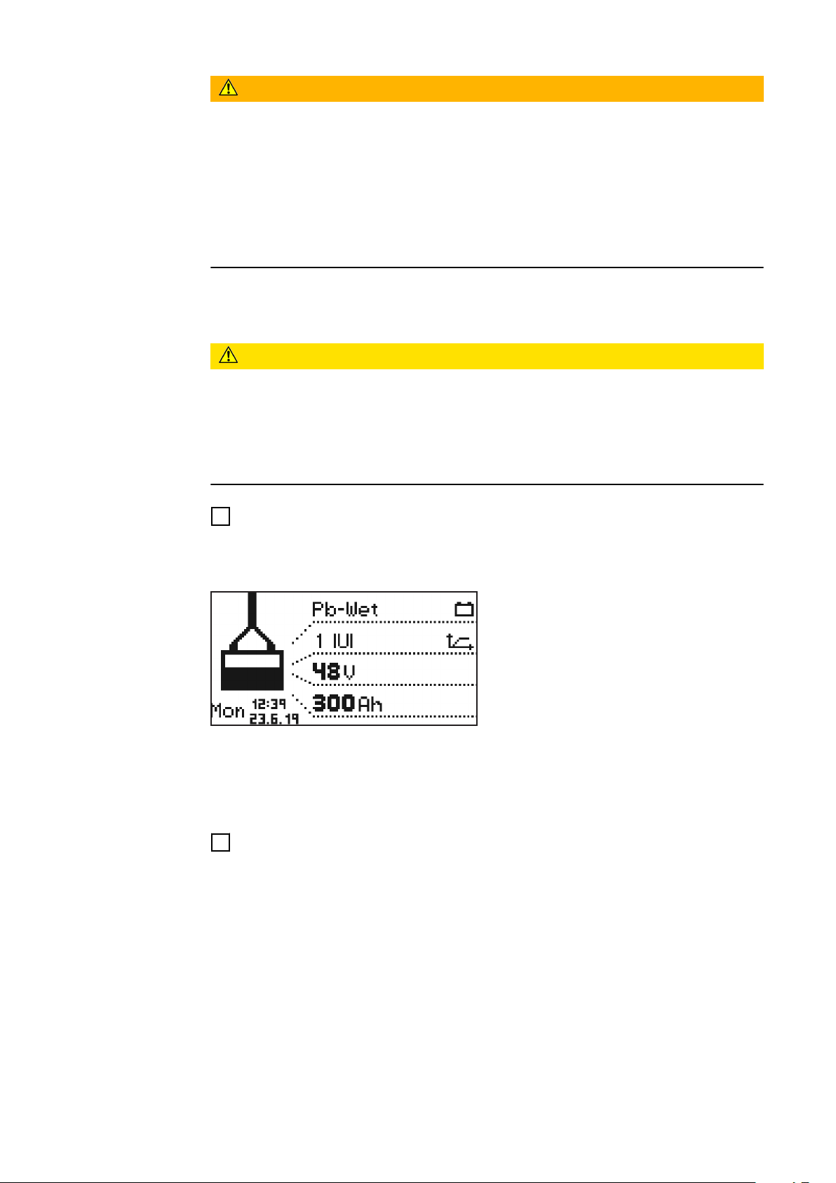
battery to be charged.
The display then appears in standard
mode. The display shows the battery
charger parameters:
Type of battery (e.g., Pb-WET)
-
Charging curve (e.g., IUI)
-
Nominal voltage (e.g., 48 V)
-
Capacity (e.g., 300 Ah)
-
Weekday, time, and date
-
The battery charger parameters can be set individually. Detailed information on
the battery charger parameters can be found in the Configuration mode section
of the "Display" chapter. Make sure that the battery to be charged corresponds
to the battery charger configuration.
Plug in the charging plug.
2
The battery charger detects the connected battery and starts charging. If the
start-up delay is activated, the charging process starts after the set delay time
has elapsed. Detailed information can be found in the Configuration mode section of the "Display" chapter.
32
During the charging process the display shows the following values:
Current charging current (A)
-
Current charging voltage (V)
-
Charge delivered (Ah)
-
Battery temperature with the "Temperature-controlled charging" option
-
Time (hh:mm) from start of charge
-
Page 33
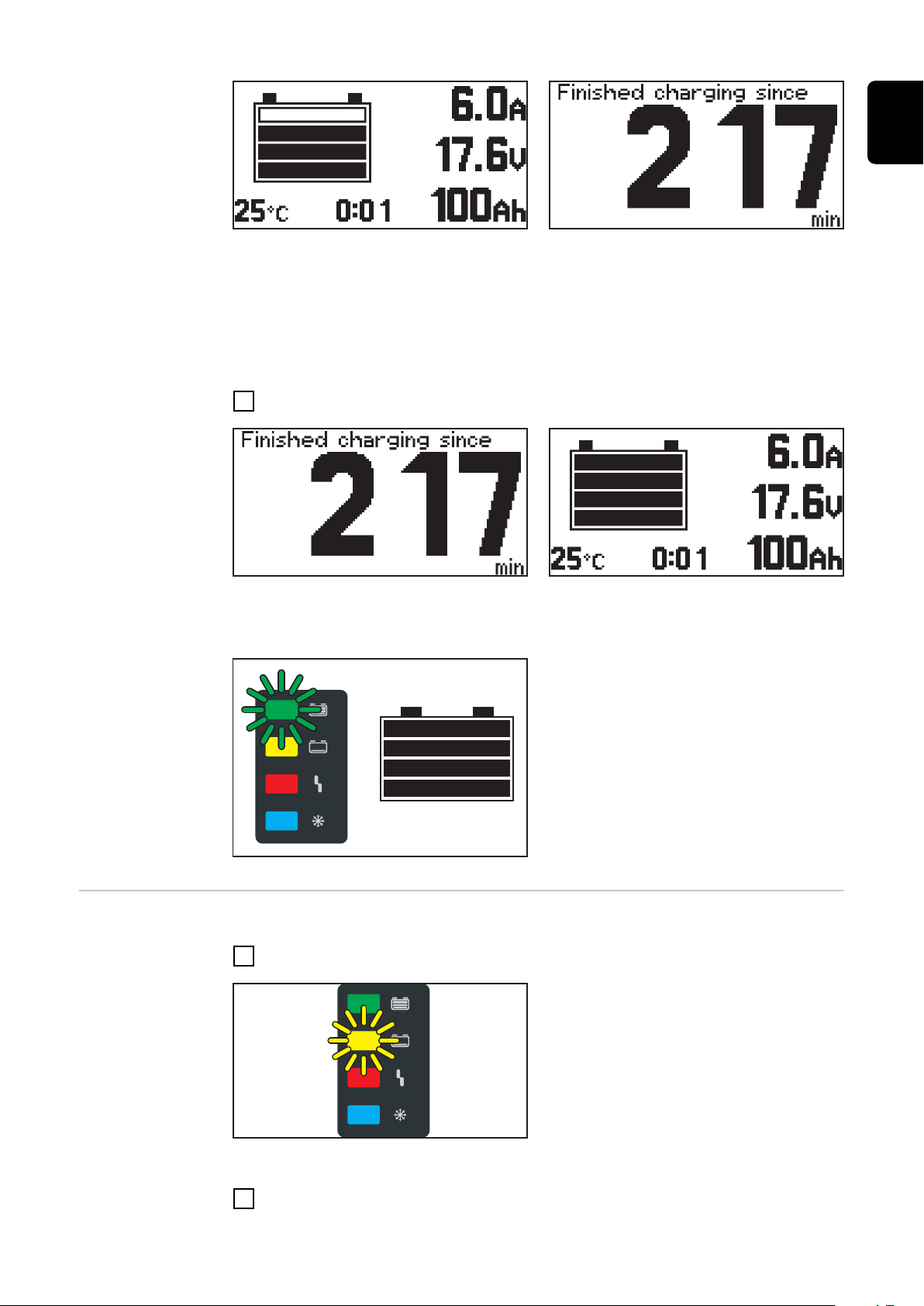
The battery symbol indicates the current state of charge. The more bars are displayed, the further the charging process has progressed. As soon as the battery
is fully charged, a minute counter appears (figure on the right). This counts the
minutes since the end of charging and makes it easier to judge which battery has
cooled down the most when using several battery chargers.
If you still want the standard display to be shown instead of the minute counter:
Use the "Up/Down" buttons to switch between the minute counter and the
1
standard display.
EN-US
Pausing the
charging process
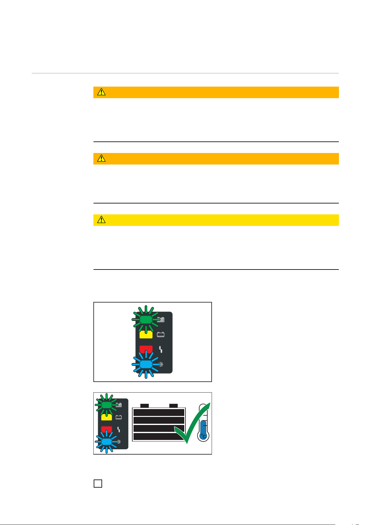
When the battery is fully charged, all 4 bars of the battery symbol appear in
black. As soon as the battery is fully charged, the green indicator lights up.
The battery is always ready for use.
-
The battery can remain connected
-
to the battery charger for any
amount of time.
The conservation charge counter-
-
acts self discharge of the battery.
Pause the charging process as follows:
Press the "Pause/Start" button.
1
While charging is paused:
The "Charge" indicator flashes (yel-
-
low).
Resume the charging process as follows:
Press the "Pause/Start" button again.
2
33
Page 34
As long as a battery is connected to the battery charger, the charging process
can be paused and resumed by pressing the "Pause/Start" button. It is only possible to change the display modes with the "Menu" button, as described in the
"Display" chapter, after disconnecting the battery from the battery charger.
Ending the charging process
WARNING!
Danger due to oxyhydrogen ignition caused by sparks when disconnecting the
charging cables.
This can result in severe personal injury and damage to property.
Before disconnecting or unplugging the charging plug, end the charging pro-
▶
cess by pressing the "Pause/Start" button.
WARNING!
Danger if the plug connection is disconnected during the charging process
This can result in severe personal injury and damage to property.
Do not disconnect the plug connection while the charging process is running.
▶
Do not touch live contacts on the charging plug.
▶
CAUTION!
Danger of battery damage when disconnecting the battery from the battery
charger if the charging process is not yet fully completed.
This can result in damage to the battery.
Do not disconnect the battery from the battery charger until it is fully
▶
charged (green "Battery is charged" indicator lights up).
Once the battery is fully charged and cooled down, the following indicators light
up:
"Battery is charged" indicator
-
(green)
"Battery cold" indicator (blue)
-
For optimum battery life, do not disconnect the battery from the battery
charger until the blue "Battery cold"
indicator lights up in addition to the
green indicator, as explained below. If
several battery chargers are in use, remove the battery that has been fully
charged (coolest) for the longest time
first.
34
End the charging process as follows:
Press the "Pause/Start" button.
1
Page 35

Disconnect the charging plug.
2
When the charging contacts are open, the automatic open-circuit detection ensures that the charging contacts are voltage-free.
EN-US
35
Page 36
Display
Overview of display modes
No. Function
Standard mode
In standard mode, the display shows the charging parameters.
Statistics mode
Visualizes the frequency of the operating states of the device and
shows the total number of charges, as well as an overview of the absolute and average Ah delivered and energy consumed per charge.
History mode
Provides information regarding the parameters of all stored charging
processes.
Configuration mode
Configuration mode enables all settings to be made for the device and
the charging process.
USB mode
USB mode supports a device update, the backup and uploading of
device configurations, as well as logging of charging parameters during
the charging process via USB thumb drive.
As long as a battery is connected to the battery charger, the charging process
can only be interrupted and resumed by pressing the "Pause/Start" button. It is
only possible to change the display modes with the "Menu" button after disconnecting the battery from the battery charger. A detailed description of the display modes is given in the following chapter.
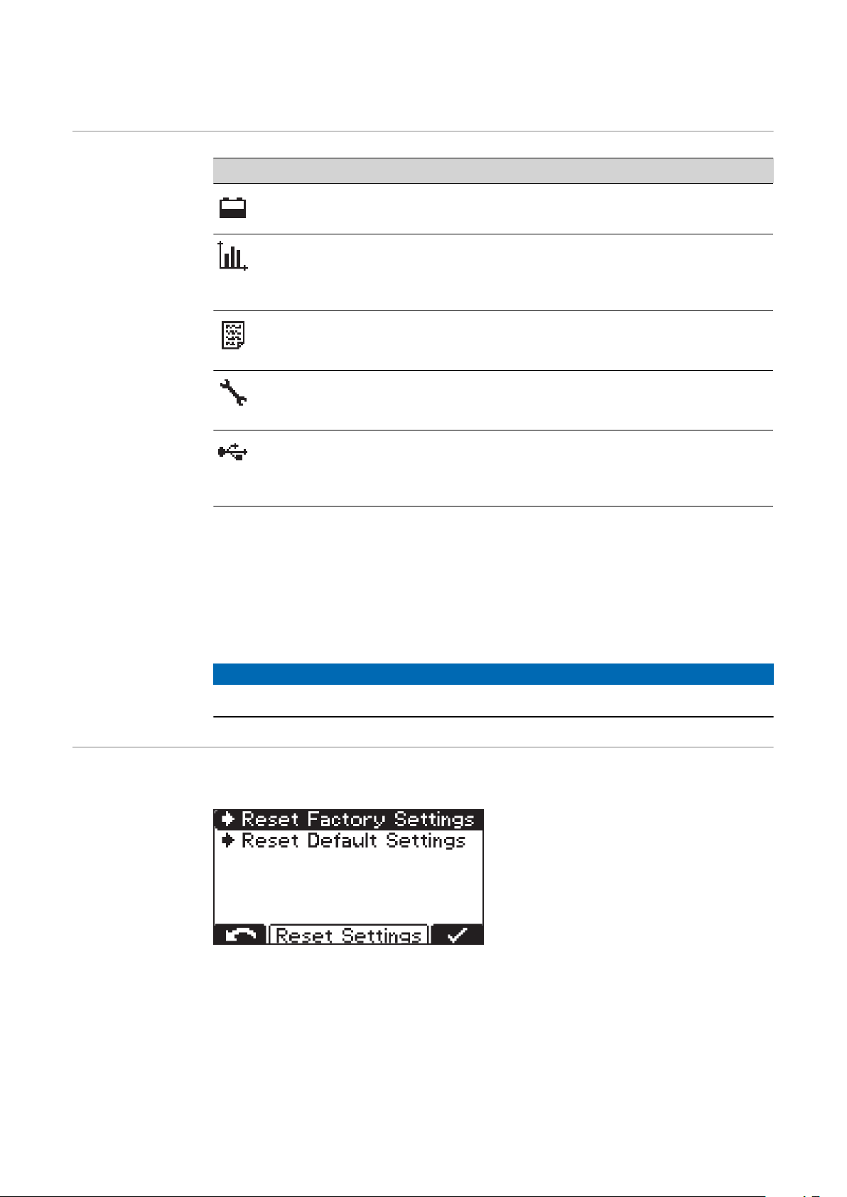
Resetting settings
A limited menu selection is available while charging has been paused.
NOTE!
A limited menu selection is available while charging has been paused.
The menu item offers 2 possibilities to reset all settings made:
Reset Factory Settings:
Reset the settings made to the
-
factory settings.
Reset Default Settings:
Resetting the settings made to the
-
manufacturer's default settings.
36
Page 37
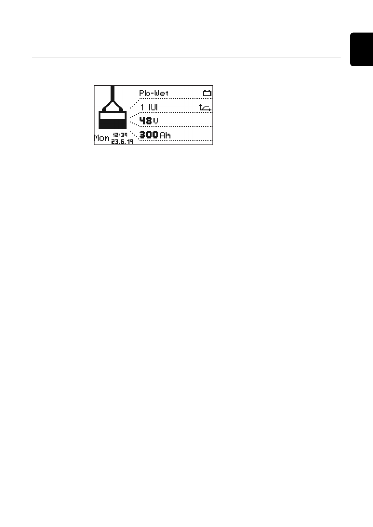
Standard mode
Standard mode After connecting the mains plug to the electrical network, the display is automat-
ically in standard mode.
In standard mode, the display shows
the battery charger parameters:
Type of battery (e.g., Pb-WET)
-
Charging characteristic (e.g., IUI)
-
Nominal voltage (e.g., 48 V)
-
Capacity (e.g., 300 Ah)
-
Weekday, date and time
-
The battery charger parameters are individually adjustable. Detailed information
can be found in the "Configuration mode" section.
EN-US
37
Page 38
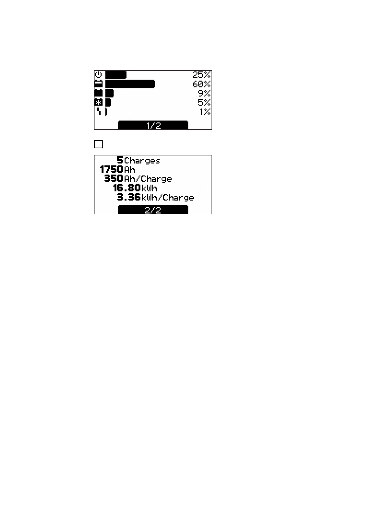
Statistics mode
Statistics mode In statistics mode, horizontal bars
visualize the frequency of the following
operating states of the device:
Idle
-
Charging
-
Conservation charge
-
Cooldown
-
Error
-
Use the "Up/Down" buttons to switch between page 1/2 and page 2/2.
1
Page 2/2 shows the following values:
Total number of charges.
-
Total Ah delivered.
-
Average Ah delivered per charge.
-
Total energy consumed (kWh).
-
Average energy consumed (kWh)
-
per charge.
The display of the consumed energy is intended as a guide value and may deviate
from the actual amount of energy by up to 5% at the rated power. The deviation
may be higher at lower power.
38
Page 39
History mode
(1)
(2)
(3)
(4)
(5) (7)
(6)
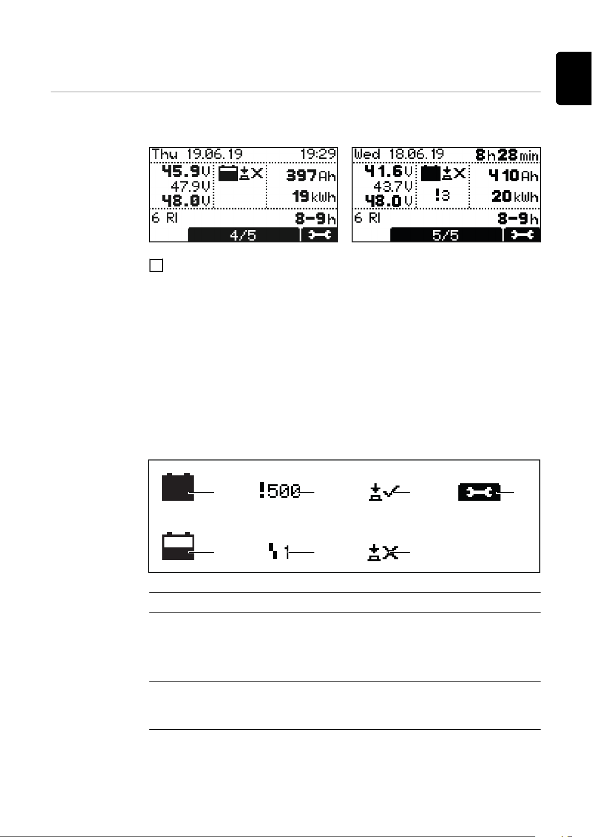
History mode History mode provides information regarding the parameters of all stored char-
ging processes. The display window is shown twice below in order to be able to
show changing or different displays:
Use the "Up/Down" buttons to switch between the pages for each saved char-
1
ging process.
Contents of the display window
Start date of the charge, e.g.: Thursday, 19.06.14.
-
Start time of the charge, e.g.: 19:29 or charging time, e.g.: 8 h 28 min.
-
Voltage at start of charging: e.g.: 45.9 V.
-
Voltage after 5 minutes: e.g.: 47.9 V.
-
Voltage at end of charging: e.g.: 48.0 V.
-
Input power Ah, e.g.: 397 Ah.
-
Input power kWh, e.g.: 19 kWh.
-
Charging curve, e.g.: 6 RI.
-
Set charging period, e.g.: 8–9 h or set Ah, e.g.: 400 Ah or set time of end of
-
charge (not shown).
EN-US
Displayed symbols
No. Function
(1) Full battery
Charge completed.
(2) Empty battery
Charge not completed.
(3) Exclamation mark with number
Warning issued, with code for the corresponding status code. Detailed information can be found in the Status codes section.
(4) Symbol with number
Error issued, with code for the corresponding status code. Detailed information can be found in the Status codes section.
39
Page 40

(5) Button symbol with check mark
Charge was correctly ended with the "Pause/Start" button.
(6) Button symbol with cross
Charge was ended without pressing the "Pause/Start" button.
(7) Charge details
Display of certain battery data at the beginning and at the end of the
charge:
Number of cells
Ah
Curve
Type of battery
40
Page 41
Configuration mode
EN-US
Overview of the
setting options
in configuration
mode
Charging settings: Settings for the battery
Type of battery, e.g., "Wet".
-
Charging curve, e.g., "IU".
-
Capacity (Ah) or charging time (h), depending on the charging curve.
-
Cells: Voltage (V) and number of battery cells or automatic setting of the
-
number of cells.
CAUTION!
Risk of damage to the battery due to incorrectly set values.
This can result in damage to property.
Only use the automatic setting of the number of cells for batteries with
▶
the following nominal voltage values: 12 V and 24 V for 24 V devices,
24 V and 48 V for 48 V devices.
Do not use the automatic setting of the number of cells on deeply dis-
▶
charged batteries.
Further settings:
-
For individual adjustment of the charging curve.
Additional functions: Additional functions
Blue LED
-
External start/stop
-
Refill indicator
-
Option section
-
At mains failure restart charging
-
Entering the
configuration
mode
General options: General settings
Language
-
Contrast
-
Time (hh:mm:ss)
-
Time zone
Daylight saving time/standard time
Date (dd:mm:yy)
-
Charging cable length (m)
-
-
Charging cable cross-section (mm2)
AC current limitation
-
Unit for temperature values
-
Code for entering the configuration menu activated/deactivated.
-
Time interval for the parameters logged on the USB thumb drive (s).
-
Reset statistics
-
Reset history
-
Reset Settings
With confirmation prompt ("OK?") for further confirmation.
-
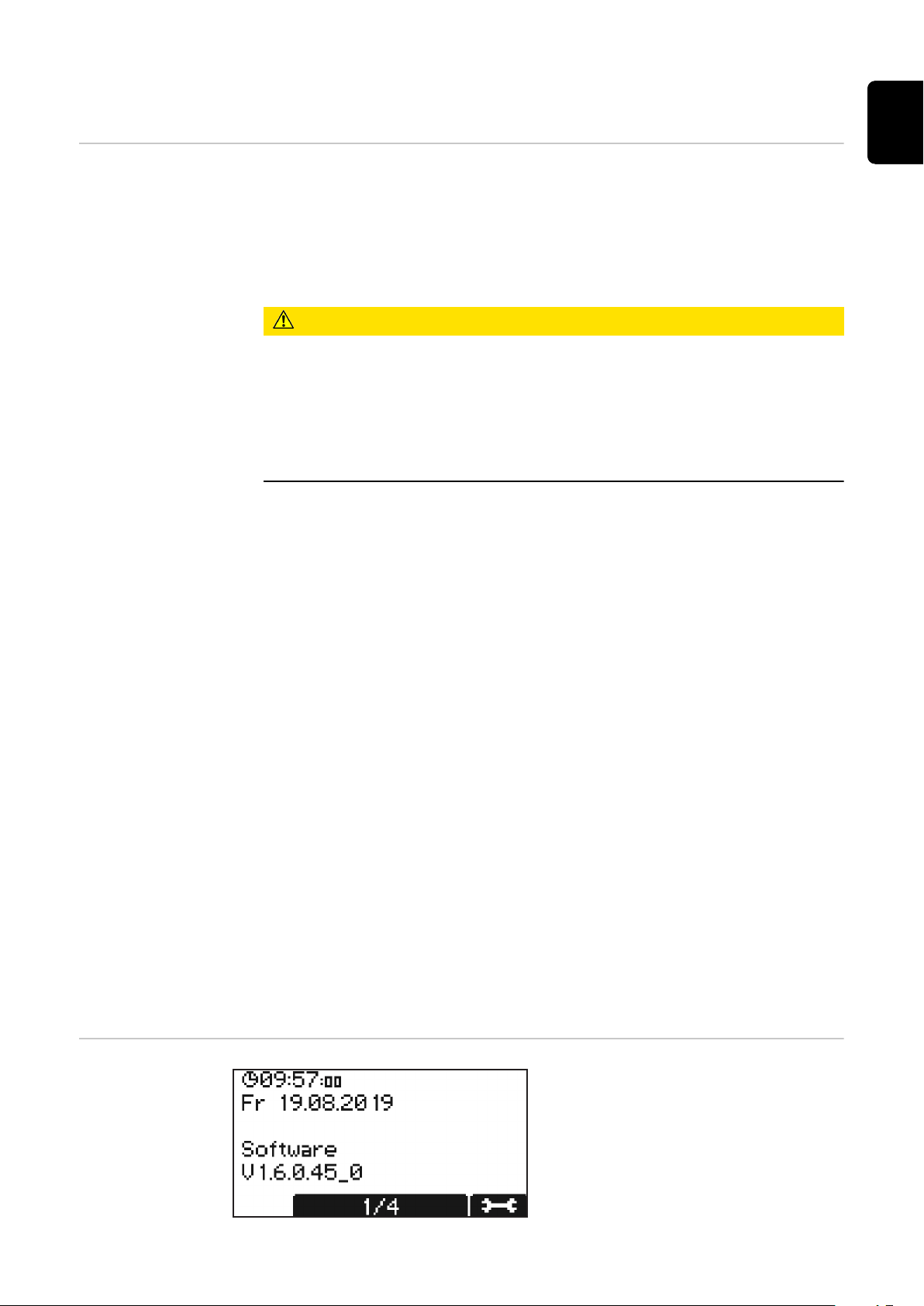
First, the screen appears in the basic
settings with display of date and time,
as well as the software version.
41
Page 42
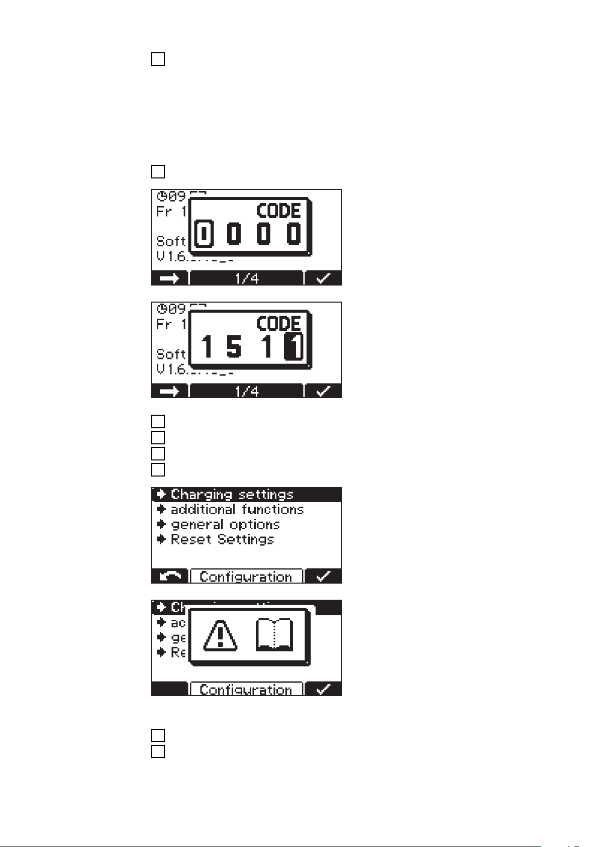
Use the "Up/Down" buttons to call up the following information:
1
Device serial number as well as serial number and version of the config-
-
uration memory.
PC board for control/power electronics: Hardware version and serial
-
number.
Software: Main software, secondary software, primary software, and
-
curve block version.
Enter the configuration menu as follows:
Press the "Pause/Start" button.
1
A prompt for the code appears.
Enter the required code "1511" as follows:
Use the "Up/Down" buttons to enter the first digit of the code.
1
Press the "Menu" button to move to the next digit of the code.
2
Continue as described above until the complete code is entered.
3
Confirm entry with the "Pause/Start" button.
4
The selection of the main menu items
for configuration mode appears.
When selecting a menu item, you may
be prompted to read the Operating Instructions. Confirm this prompt by
pressing the "Pause/Start" button
again.
42
Navigate through the configuration menu and its submenus as follows:
Use the "Up/Down" buttons to select the desired menu item.
1
Press the "Pause/Start" button to confirm the menu item and confirm any
2
confirmation prompts (e.g., "OK?") again.
Page 43
If necessary, use the "Up/Down" buttons to make a selection, e.g., "Off/On" or
3
enter a value.
Press the "Pause/Start" button to confirm the entry.
4
If the cursor moves to the next setting or digit after confirming, proceed
5
again as described in points (3) and (4)
To exit the current menu:
Press the "Menu" button to return to the higher-level selection.
6
EN-US
Exiting configuration mode
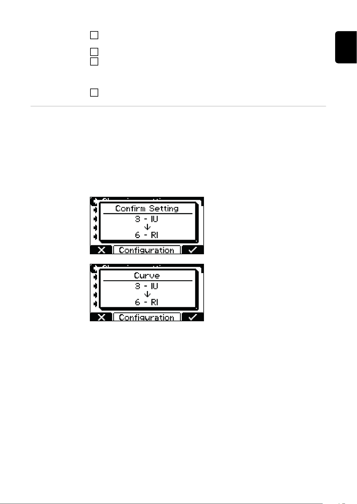
If one or more relevant settings for the charging process are changed in configuration mode, another prompt appears when exiting configuration mode, asking
whether the setting in question should be applied.
The following settings must be confirmed when exiting configuration mode:
Curve
-
Battery capacity in Ah (RI curve excluded)
-
Number of cells
-
Equalizing charge ON/OFF
-
CAN protocol
-
Example:
Change to the curve from 3 - IUI (PbWET) to 6 - RI (Pb-WET).
If the setting is not confirmed, the battery charger returns to configuration
mode and the setting can be changed
to the desired value.
43
Page 44
USB mode in configuration mode
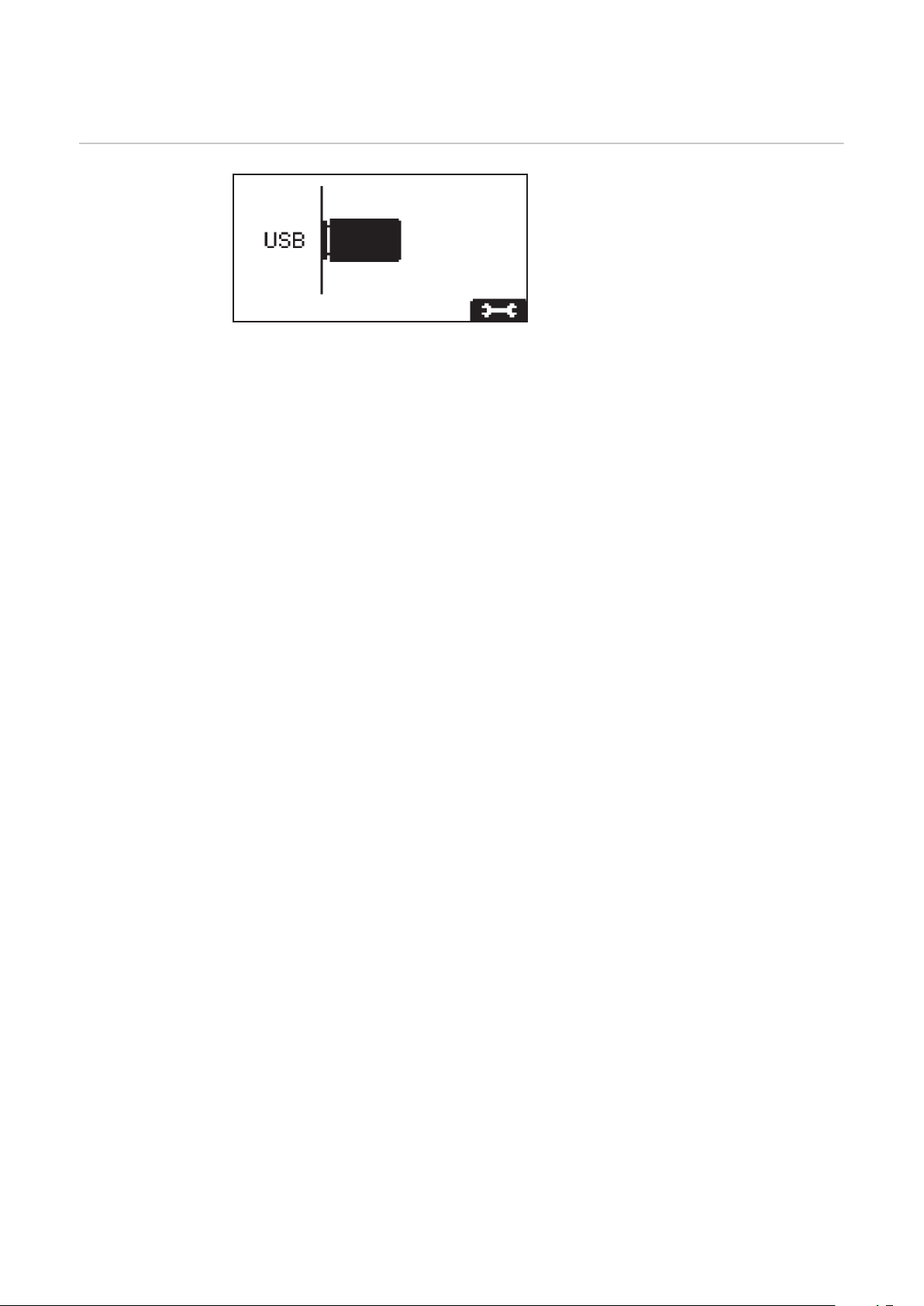
USB mode In USB mode, the display shows
whether a USB thumb drive is plugged
in.
The USB thumb drive must meet the
following specifications:
Formatting: FAT32
-
32 Gigabyte maximum
-
No multiple partitioning
-
The I-SPoT-VIEWER software (www.fronius.com/i-spot) supports the visualiza-
tion and evaluation of the data on the USB thumb drive.
To start a data download, confirm this again with the "Pause/Start" button. If this
repeated confirmation with the "Pause/Start" button is not carried out, the
download starts automatically after one minute.
While a charging process is in progress, the USB thumb drive may be connected
after pressing the "Pause/Start" button. It is only possible to read data and not to
perform an update or load a configuration.
Safely remove
Safely remove the USB thumb drive once the desired action is complete.
-
Update
A list of suitable update files stored on the USB thumb drive opens.
-
The desired file is selected and confirmed in the same way as scrolling
-
through the settings.
Do not rename the automatically assigned file name of the update file!
-
The latest firmware is available in the download area of the Fronius website.
-
Firmware installation instructions are included in the zip file of the down-
-
load.
Download
The data of the logged charging parameters stored in the datalogger of the
-
device are saved for the I-SPoT VIEWER on the USB thumb drive.
Events as well as device settings and user curves (configuration) are also
-
saved.
The following time ranges can be selected for the data logger:
-
1 month
3 months
All
Since last time
44
Page 45

Download optional
The following options are available:
I-SPoT VIEWER
-
The logged data is saved in the same way as for the "Download", but only with
the data for the I-SPoT VIEWER.
Save data logger
-
The logged data is saved in the same way as for the "Download", but as "csv"
files rather than in the I-SPoT VIEWER format.
(Automatically created folder structure for the ".csv" files: *
Fronius\<Device serial number>\Charges\<yyyymmdd>\<hhmmss.csv>)
Save events.
-
Events are saved on the USB thumb drive.
Save configuration.
-
The device settings are saved on the USB thumb drive.
Load configuration
Loads a suitable device configuration stored on the USB thumb drive into the
-
device.
Load dealer text
Here a text file can be loaded from the USB thumb drive, which is displayed
-
as soon as the device is in an error state.
The text file can contain the contact details of the distributor, for example.
-
The file must be saved on the USB thumb drive in the ".txt" format in "uni-
-
code".
The file name must be "dealer.txt".
-
The number of characters is limited to 99.
-
EN-US
* If a USB thumb drive is plugged in during charging, the csv files are saved
directly on the USB thumb drive. The folder structure, which is also created automatically, contains the "Datalog" folder instead of the "Charges"
folder.
45
Page 46
Charging settings in configuration mode
Overview of
charging settings
Electrolyte circulation
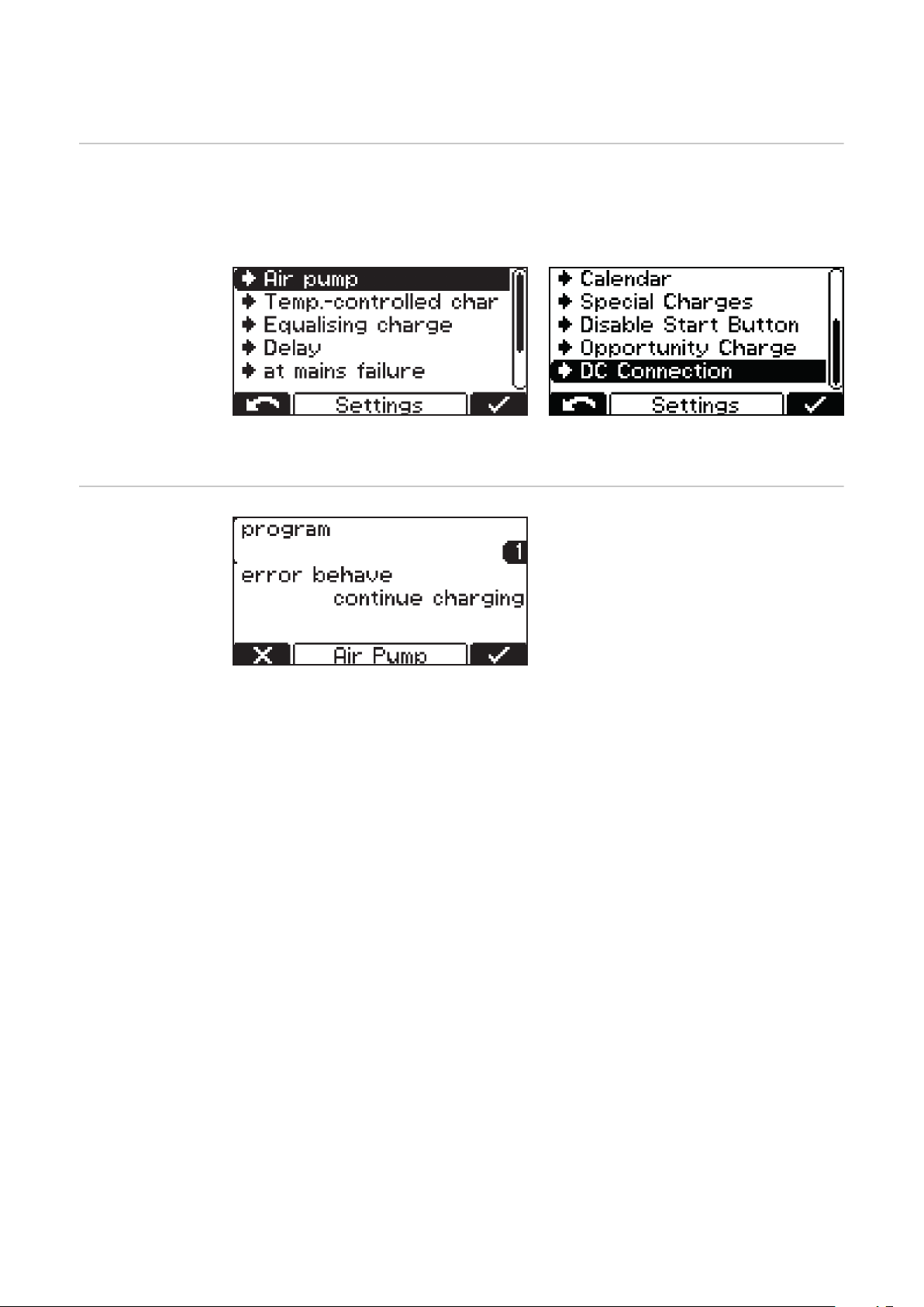
Below is a detailed explanation of the "Settings" menu item, selected under the
aforementioned "Charging settings" menu item. Navigation is carried out as described in the Configuration mode section.
A list appears with the following selection options:
The individual selection options are explained in detail below.
Electrolyte circulation "Air Pump"(not
available with the Selectiva 220 V and
Selectiva UL version):
The sequential control of the electrolyte circulation takes place via the battery charger control unit. Several selection options are available for this
purpose.
The following settings are available for the electrolyte circulation:
Off
Electrolyte circulation switched off.
-
Continuous
Electrolyte circulation constantly switched on.
-
Program 1 to 5
Factory-set programs for the electrolyte circulation and their relevant para-
-
meters can be found in the table in the "Settings" section of the "Display"
chapter.
Automatic
Automatic adjustment of the flow rate of the electrolyte circulation based on
-
the set battery parameters.
User "On"/"Off"
Individual setting for the electrolyte circulation.
-
The "On" and "Off" settings determine the pulse/pause ratio of the airflow in-
-
tervals.
Factory-set programs for the electrolyte circulation and the relevant parameters
are shown in the table below:
46
Page 47
Program ON 1 OFF 1 Repeat ON 2 OFF 2
1 30 min 25 min 1 x 5 min 25 min
2 3 min 10 min 4 x 3 min 20 min
3 3 min 12 min 1 x 3 min 12 min
4 5 min 10 min 3 x 5 min 20 min
5 2,5 min 7,5 min 1 x 2,5 min 7,5 min
In each of these programs, the solenoid valve picks up for an "ON 1" time and
drops out for an "OFF 1" time. This process repeats as many times as specified
for "Repeat". After this number of repetitions has elapsed, the "ON 2" and "OFF
2" times continue until the end of charging.
EN-US
Temperaturecontrolled charging
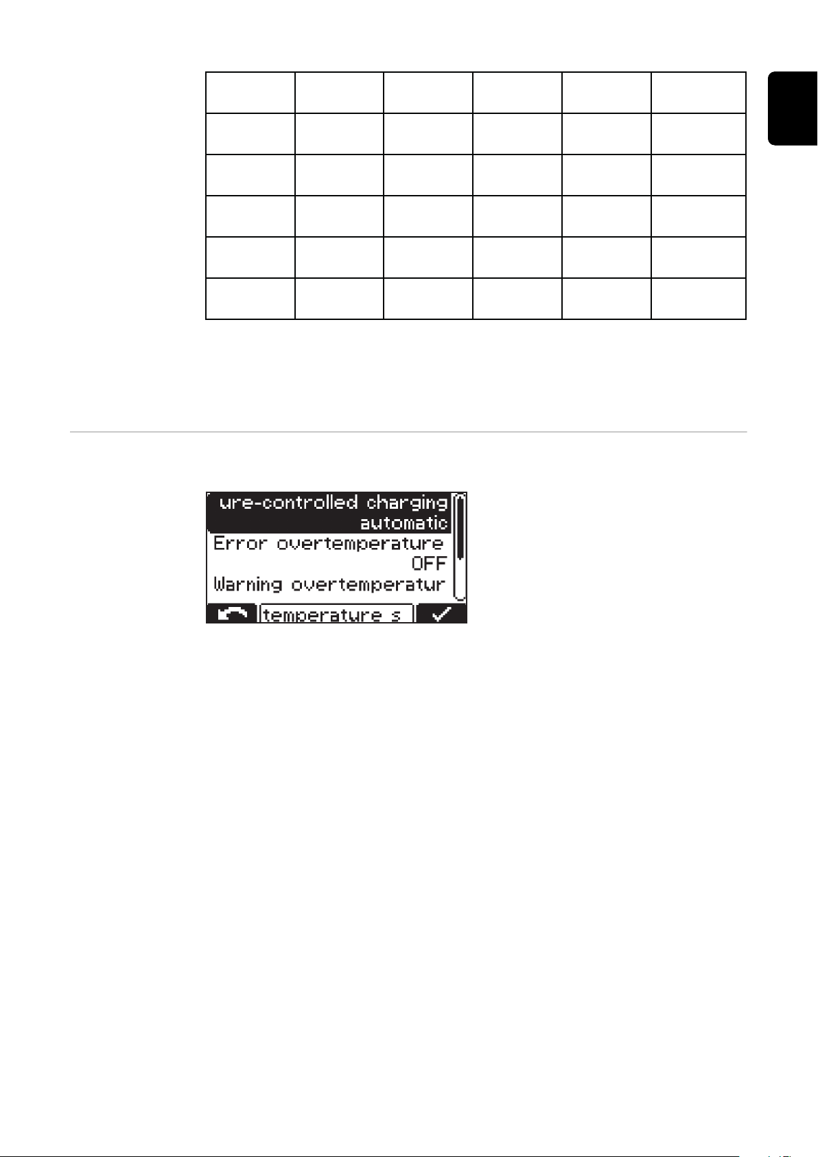
Temperature-controlled charging:
(not available with the Selectiva UL
version)
The following settings are available for temperature-controlled charging:
automatic/OFF/required
automatic ... Temperature-dependent adjustment of the charging curve.
-
OFF ... The measured battery temperature is not taken into account.
-
required ...
-
Charging only starts when the temperature sensor is connected.
Error overtemperature ON/OFF
ON ... An error message is output in the event of a battery overtemperature.
-
The charging process stops and can only be continued after the battery has
cooled down and been reconnected.
OFF ... No error message in the event of a battery overtemperature.
-
Warning overtemperature ON/OFF
ON ... A warning is output in the event of a battery overtemperature.
-
OFF ... No warning in the event of a battery overtemperature.
-
For certain curves, an external temperature sensor is required. If such a curve is
selected in configuration mode, a message is displayed indicating that an external
temperature sensor is required.
The following curves require an external temperature sensor:
28 - FCC IUI - CSM WET
-
30 - FCC IUI - WET
-
47
Page 48
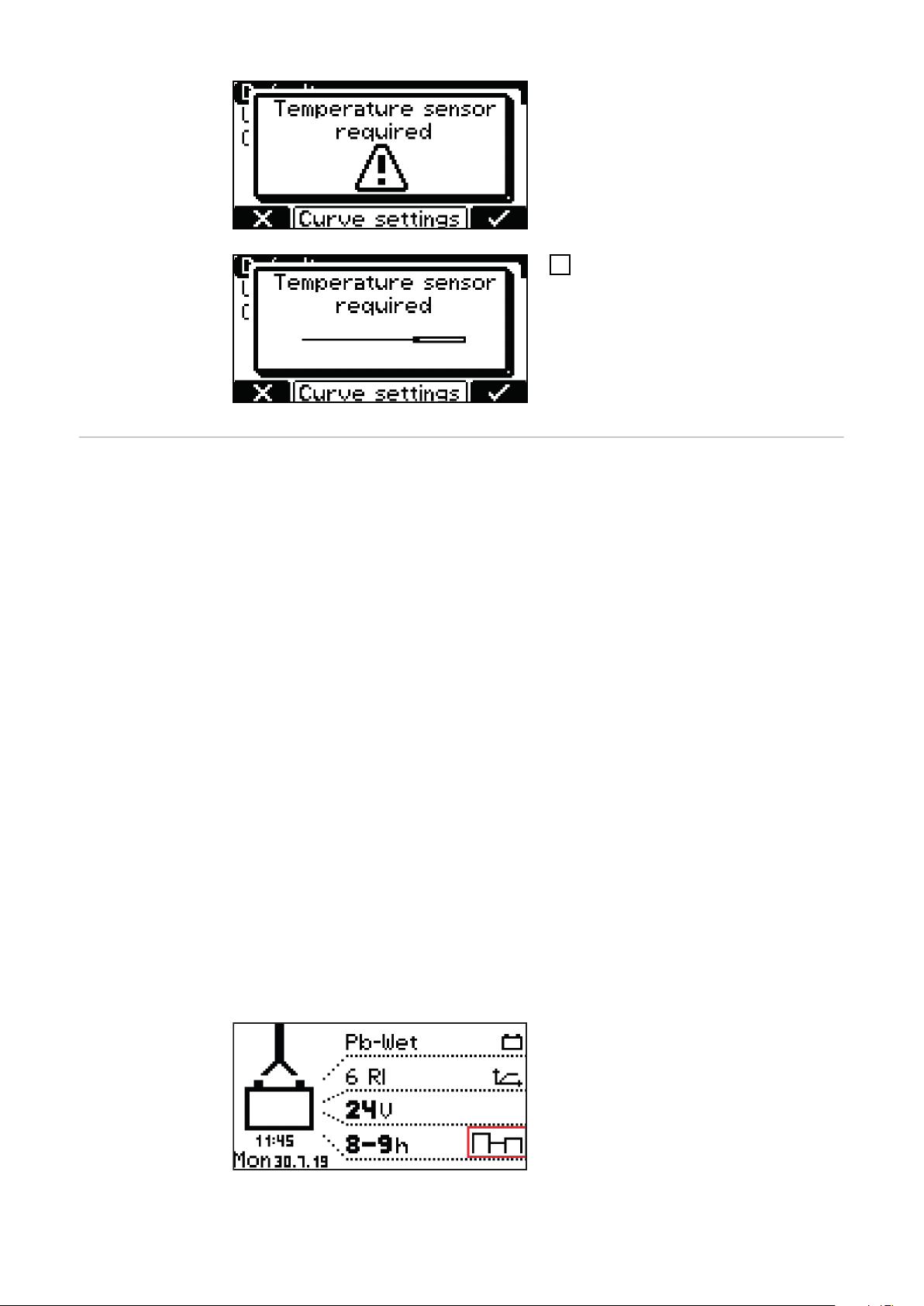
If a curve is selected that requires an
external temperature sensor, a message appears.
Confirm the message by pressing
1
the "Pause/Start" button.
Equalizing
charge
Equalizing charge
OFF
No equalizing charge takes place.
-
Delay
If the battery remains connected to the battery charger for the duration of
-
the set equalising charge delay, a special form of charging takes place. This
prevents acid stratification.
The parameters for current (amperes/100 ampere hours), voltage (volts/
-
cell), and duration of the equalizing charge can be changed.
Weekday
Specification of the day of the week on which the equalizing charge is to take
-
place.
The parameters for current (amperes/100 ampere hours), voltage (volts/
-
cell), and duration of the equalizing charge can be changed.
Manual
An equalizing charge can be activated manually by pressing a button on the
-
display.
The equalizing charge starts after the set delay with the set parameters.
-
The parameters for current (amperes/100 ampere hours), voltage (volts/
-
cell), and duration of the equalizing charge can be changed.
This function is only available for Pb-WET curves.
-
48
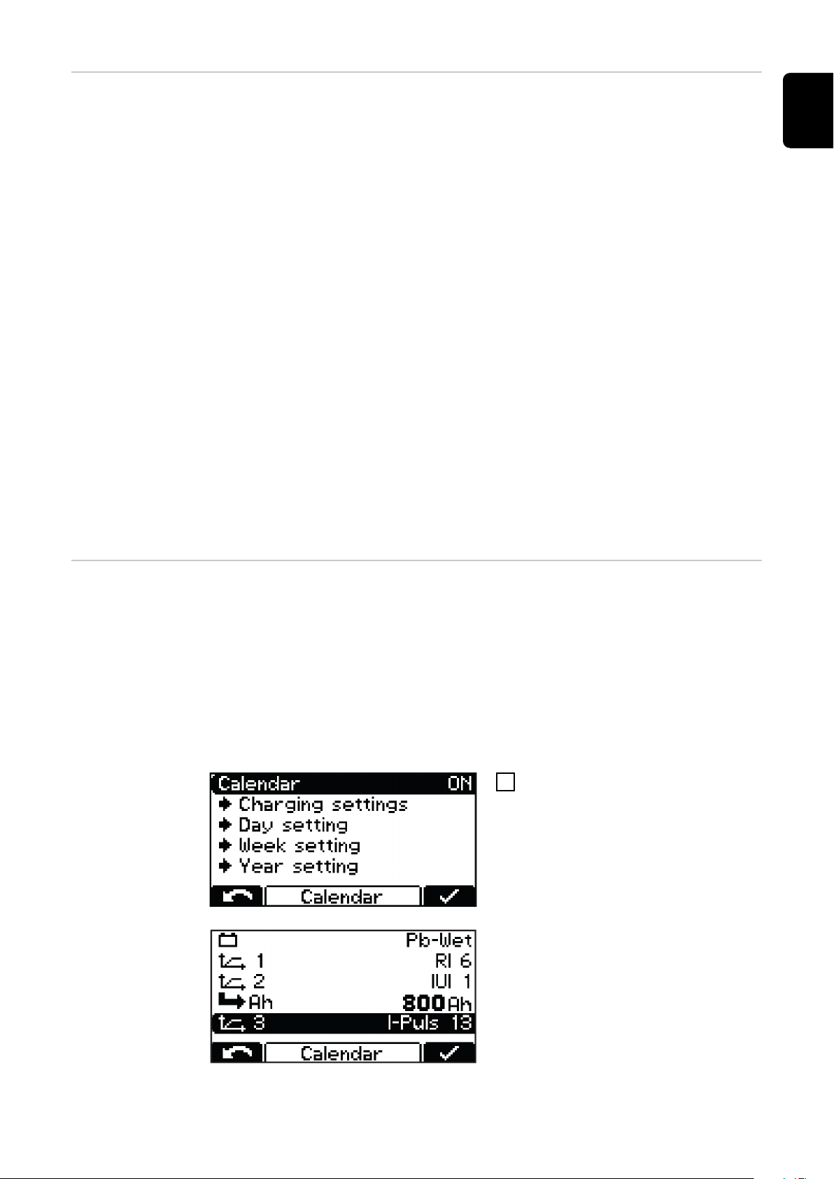
If a setting for the equalizing charge is activated, a symbol next to the set
ampere hours/the set charging time in the home screen indicates whether the
equalizing charge is being carried out or can be started.
Page 49
Delay Delay
Charge start delay
Delay time (minutes) between the activation time of the charge start and the
-
actual charge start.
Charge end delay
Delay time (minutes) between the signaled charge end (e.g., green indicator)
-
and the actual charge end.
at mains failure restart charging
If this option is activated, the charging process is automatically restarted
-
after a fault in the electrical grid as soon as the electrical grid is available
again.
at mains failure
Restart charging
-
Automatic/continue charging
-
If the "Restart charging" option is activated, the charging process is automatically restarted after a fault in the electrical grid as soon as the electrical grid is
available again.
If the "Automatic/continue charging" option is activated, the charging process is
automatically continued after a fault in the electrical grid as soon as the electrical grid is available again.
EN-US
Calendar calendar
The calendar function enables charging to be started automatically according to
the following criteria:
Time window within which charging should not be started when a battery is
-
connected.
Time window within which a defined curve 1 should be started when a bat-
-
tery is connected.
Time window within which a defined curve 2 should be started when a battery
-
is connected.
To activate the calendar function,
1
select and confirm the "ON" setting.
"Charging settings" menu item:
Type of battery for all curves:
-
e.g. Pb-WET.
Curve settings when the corres-
-
ponding curve is selected.
Further settings are possible within the calendar function:
49
Page 50
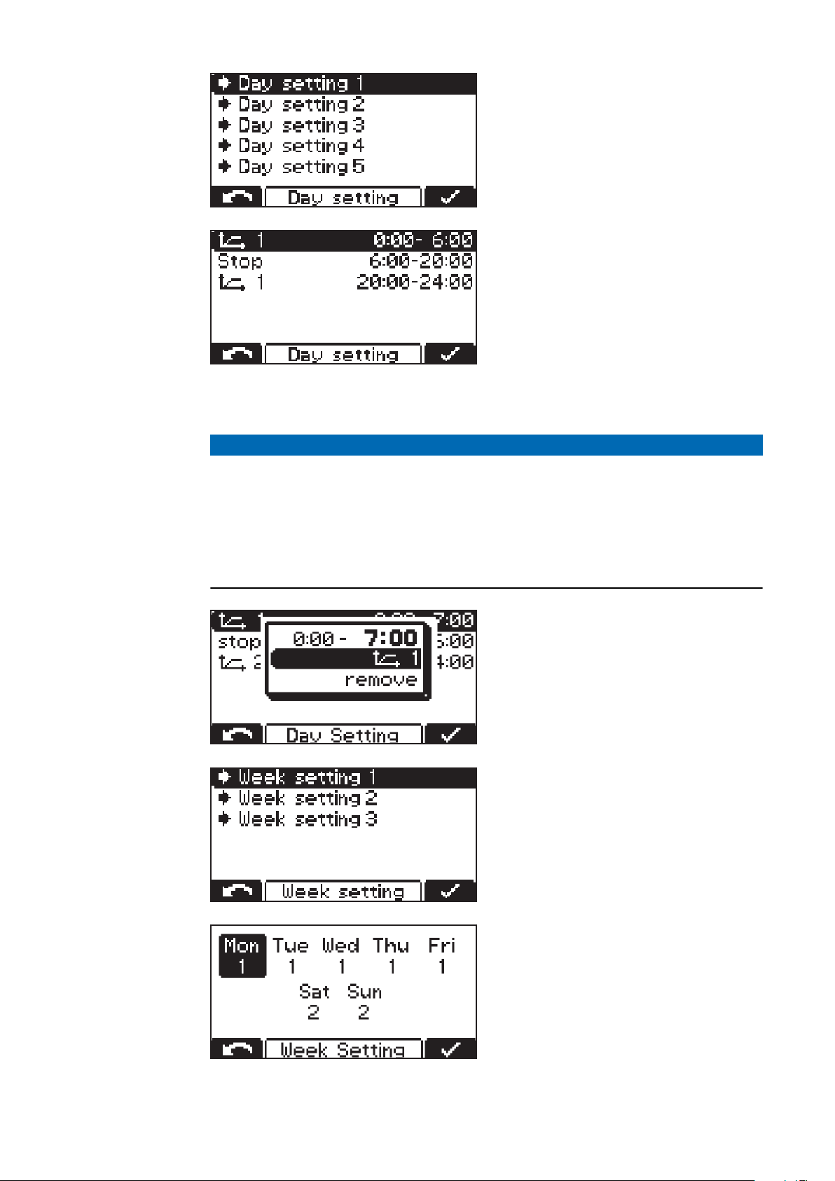
"Day setting 1-5":
The day settings allow up to 5 different
charge start time profiles to be
defined, with the following setting options:
Symbol for curve 1:
-
Time window within which curve 1
should be started (e.g.: 0:00–6:00)
Stop:
-
Time window within which no charging should take place (e.g.: 6:00–
20:00)
Symbol for curve 1:
-
Time window within which curve 1
should be started (e.g.: 20:00–
24:00)
NOTE!
Ongoing charges are not influenced by the set time windows.
If a battery is connected at 05:45 in the above example, charging is stopped
▶
when necessary and is not interrupted by the specified charge end time (6:00
in the example) of the set time window.
If the battery is connected within the stop time window, charging will start
▶
automatically in the next time window. If a manual charge start is triggered
during the stop time window, charging always takes place with curve 1.
Additional setting options:
Change the assigned curve:
-
curve symbol.
Remove the curve in question:
-
"remove".
"Week setting":
It is possible to configure 3 differ-
-
ent week settings.
Each day of the week can be assigned
one of the previously created day settings.
50
Page 51
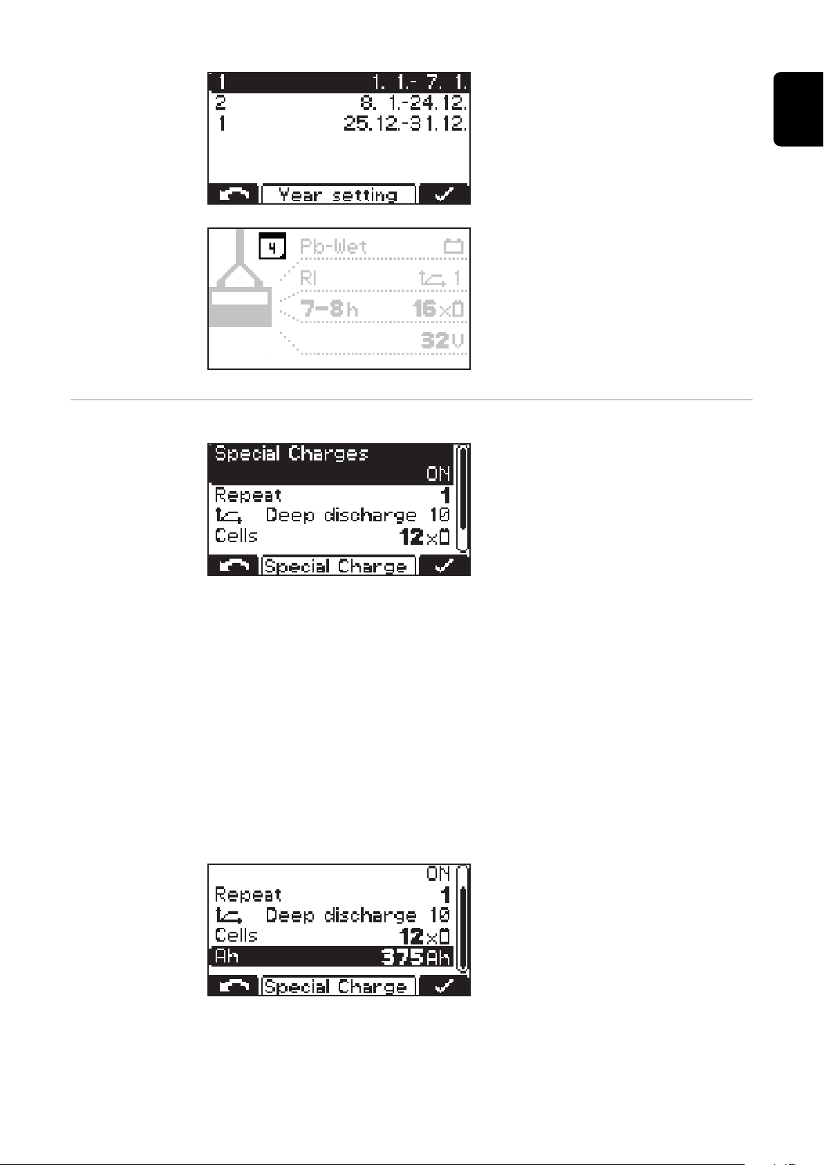
Special charges Special Charges
"Year setting":
It is possible to assign a week set-
-
ting to several calendar periods
(e.g., 1.1.–7.1.).
When the calendar function is activated, a calendar symbol (here with the
number "4" as the current date) appears in the display.
The "Special Charges" selection allows
you to temporarily carry out one or
more charges that differ from the usual type of charge.
EN-US
The "Repeat" setting defines how often the special charge is to be carried out until charging is permanently resumed with the original charge parameters:
Setting range
1 to 99 repetitions
-
Disable Start Button
ON
It is not possible to start the charging process using the "Pause/Start" but-
-
ton, which prevents unauthorized access, for example.
OFF
It is possible to start the charging process using the "Pause/Start" button.
-
The following settings are also possible:
Curve:
-
e. g. "Deep discharge 10"
-
"Cells" - e.g. 12x
Battery capacity in Ah:
-
e. g. 375 Ah
51
Page 52
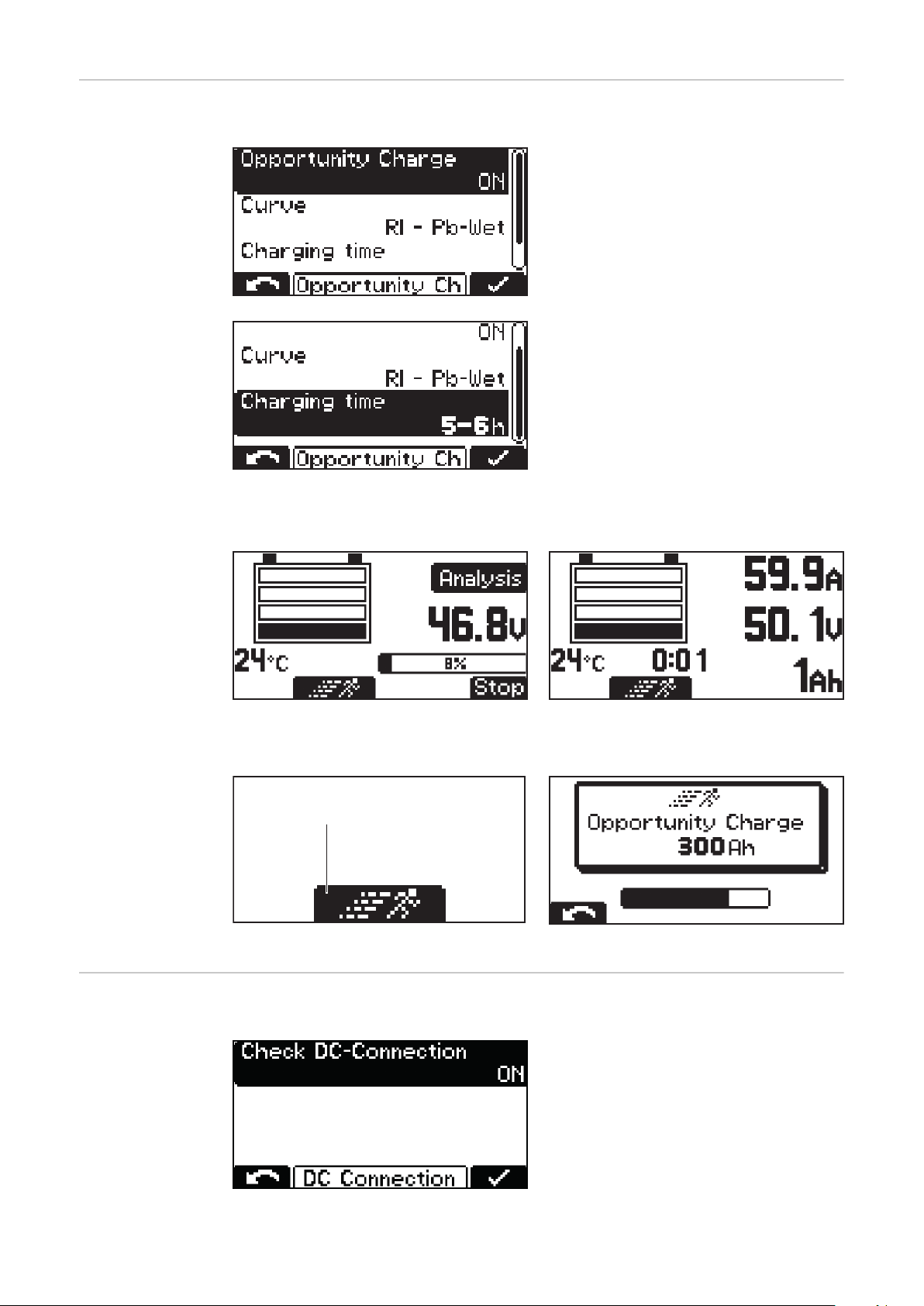
Special function
(1)
- opportunity
charging
Special function - Opportunity Charge
In order to extend the operating interval of the battery, it is possible, for example, to recharge the battery during a
break in operation.
The following curve settings are possible:
-
"Curve" - e.g. RI - Pb-WET
-
"Charging time" - e.g. 5-6 h
With opportunity charge set to "ON" and the battery connected, the following
display appears:
Display when RI curve is selected
Start opportunity charge:
Select the "Runner symbol" (1) with the "Up" button.
-
Runner symbol (1)
DC-Connection DC-Connection:
Display for other curves (e.g. IUI)
Display at start of opportunity charge
The Check DC-Connection setting is
located in the DC Connection menu.
If Check DC-connection is switched on
("ON"), the connection between the
battery charger and the battery is
checked during the charging process.
52
Page 53
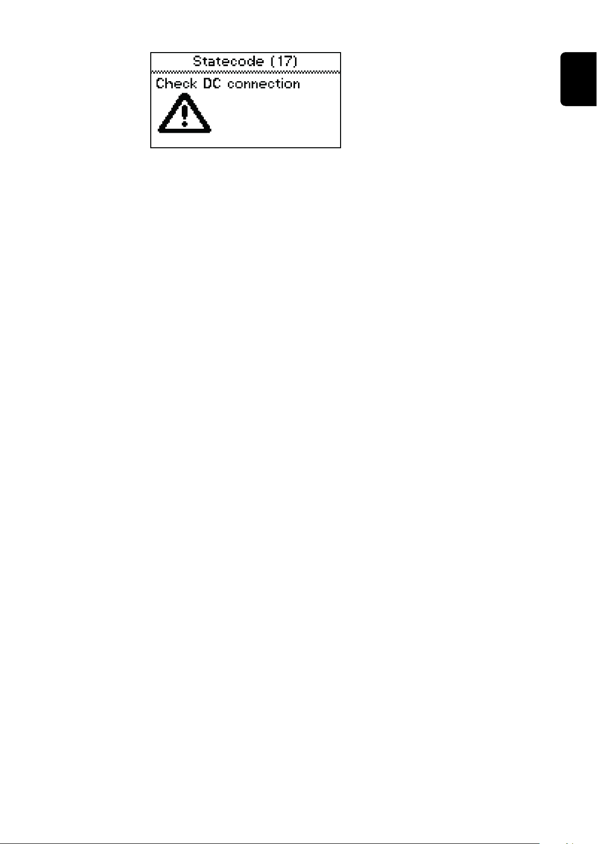
If problems occur with the DC-Connection during the charging process,
status code 17 is set when Check DCConnection is active.
A connection problem can occur, for
example, if the charging contacts are
worn or dirty.
EN-US
53
Page 54
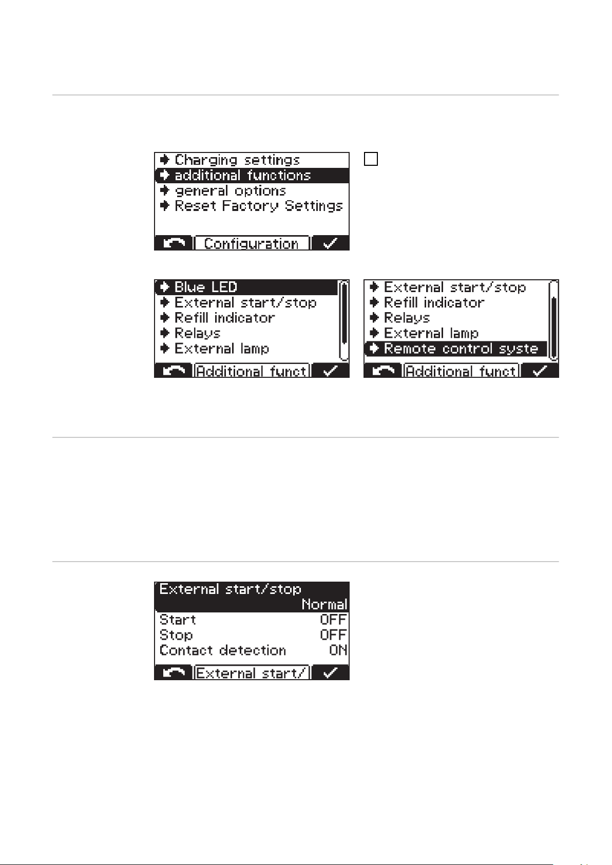
Additional functions in configuration mode
Overview of additional functions
Detailed explanation of the "Additional functions" menu item in configuration
mode. Navigation is carried out as described in the "Configuration mode" section.
Select the "Additional functions"
1
menu item.
A list appears with the following selection options:
The individual selection options are explained in detail below:
Setting for the
"Blue LED" indicator
External start/
stop
Setting for the time (minutes) after which the blue "Battery cold" indicator
should light up to indicate that the battery is sufficiently cooled down. The set
value is the time from the charge end.
In conjunction with the "Temperature-controlled charging" option, it is possible
to set a temperature value below which the blue "Battery cold" indicator should
light up to indicate that the battery is sufficiently cooled down.
The following settings are available for external start/stop:
Button
The function of the "Pause/Start" button can be simulated by means of an
-
external button.
54
Page 55
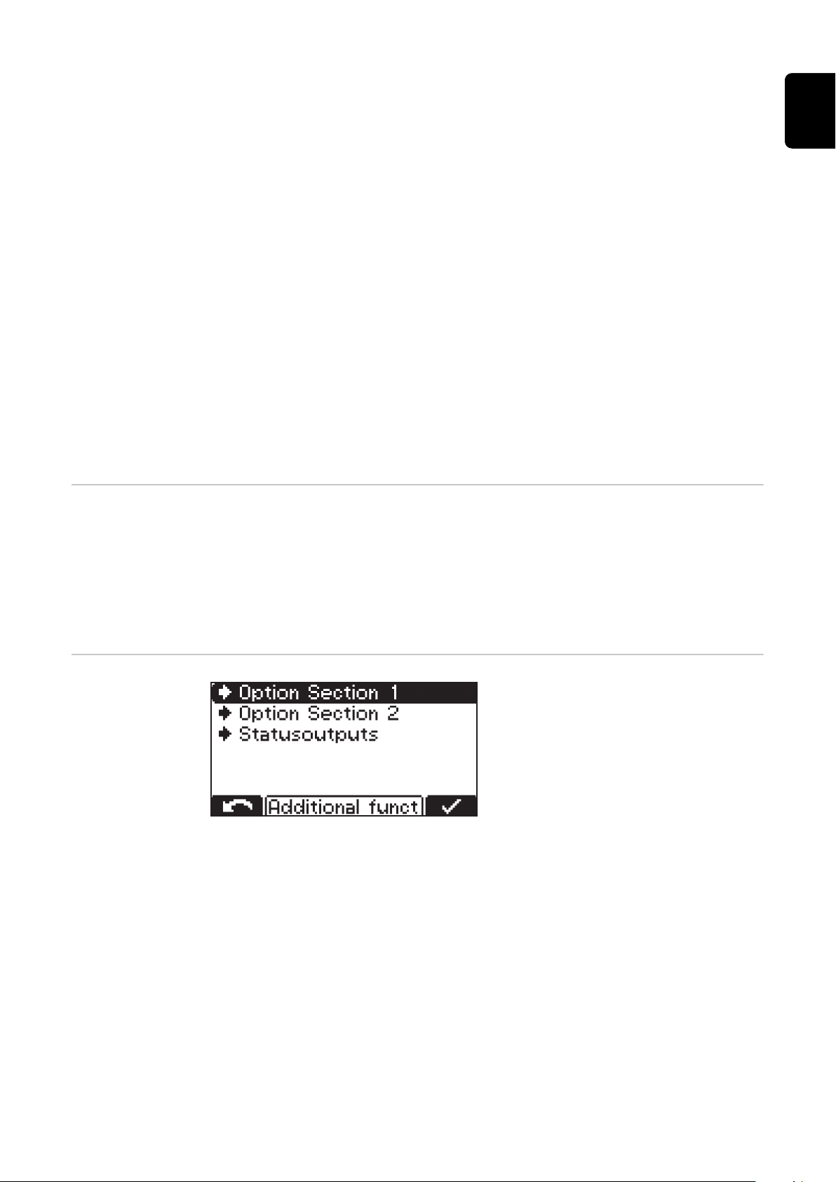
Normal
Start ON:
-
Charging starts when an external switch is closed and a battery is detected
or when the charging plug is connected by closing the auxiliary contacts and
a battery is detected.
Start OFF:
-
Charging starts when a battery is connected.
Stop ON:
-
Charging is interrupted when an external switch is opened
or when the charging plug is disconnected by opening the auxiliary contacts.
Stop OFF:
-
The opening of an external switch or the auxiliary contacts is ignored.
Contact detection
ON:
-
If a battery is connected when "Start ON" is set and the external start/stop
contact is not closed, the status code (16) "External start/stop is not closed"
appears.
If charging has been started when "Stop ON" is set, the external start/stop
contact is opened and the battery is not fully charged, and the status code
(16) "External start/stop is not closed" appears.
OFF:
-
Contact detection is not executed.
EN-US
Refill indicator The refill indicator is activated as soon as it is necessary to add distilled water to
the battery. The time of the refill request can be defined as follows:
Every x-th week and weekday
e.g. refill water every 2nd week on Friday
-
When "OFF" is set, the refill request does not have to be confirmed.
Option section
Option section 1
Setting options:
-
CAN1 (option box)
Cool Bat Guide Easy (Fronius variant only)
Option section 2 (3 kW only)
Setting options:
-
CAN2 (option box)
Air Puls (EUW)
Status outputs (3 kW only)
External lamp setting (normal or RGB)
-
55
Page 56

At mains failure restart charging
If this option is activated, the charging process is automatically restarted after a
fault in the electrical grid as soon as the electrical grid is available again.
56
Page 57
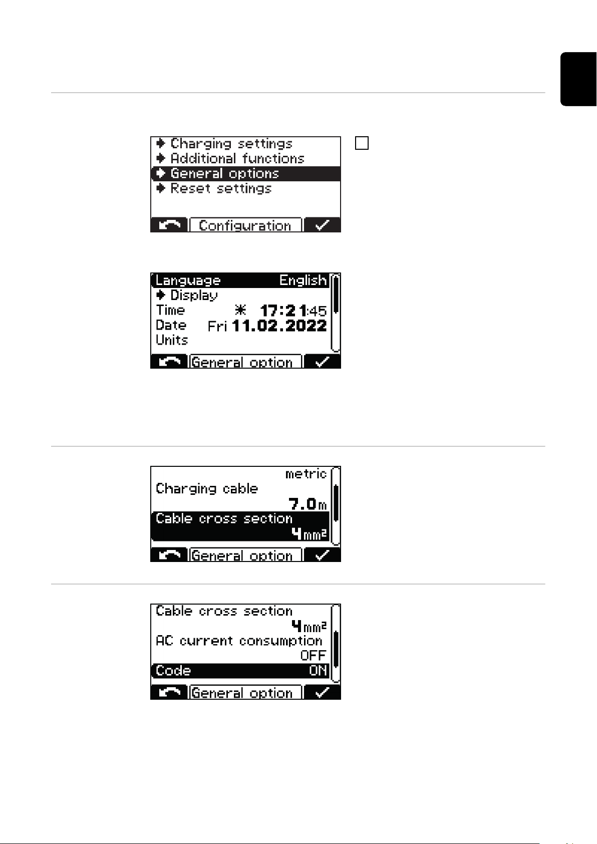
General settings in configuration mode
EN-US
Overview of general settings
Detailed explanation of the "General options" menu item in configuration mode.
Select the "General options" menu
1
item.
A list appears with the following selection options:
Language
-
Display settings
-
Contrast
-
LED brightness
-
Show Ah at charge end
-
ON/OFF
Time and Date
-
Daylight saving time/standard
-
time
Predefined time zones
-
User-defined time zones
-
Units:
-
metric / imperial
-
Charging cable
settings
AC current limitation
Charging cable:
Simple length of the charging
-
cable (m / ft)
Cable cross section:
Cross section of the charging
-
cable (mm² / AWG)
Adaptation of the maximum device
-
current to the electrical installation on site, or to the device plug
which has been installed on the
device.
57
Page 58
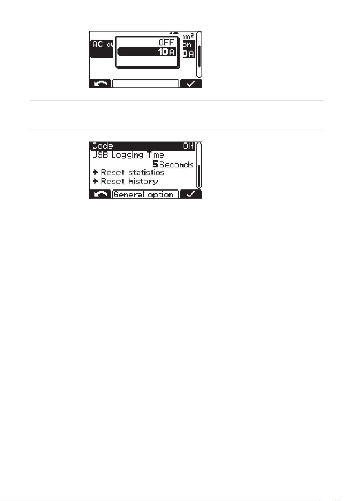
The minimum and maximum values
-
differ for the different device
classes. The minimum value is approx. 25% of the maximum nominal current of the device concerned.
Code Code entry required/not required to enter configuration mode ("Code ON/OFF")
USB time interval
Time interval for the charging
-
parameters logged on the USB
thumb drive (s) ("USB Logging
Time")
Reset statistics
Reset history
Detailed information regarding statistics and history can be found in the "Statistics mode" and "History mode" sections.
58
Page 59
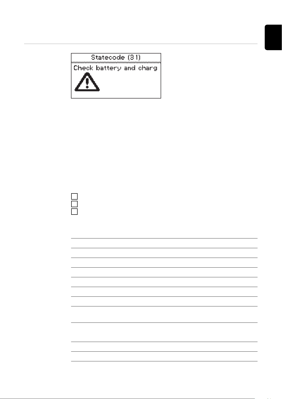
Status codes
Status codes
If a fault occurs during operation, specific status codes may be displayed. This
can be caused by the following:
Battery error
-
A battery with an unsuitable voltage has been connected.
-
The device has overheated.
-
A software or hardware error has occurred.
-
Battery error:
If the battery reports an error state, the battery charger will display this error as
a battery error including the corresponding error number of the battery. The respective error explanation can be found in the Operating Instructions for the
battery.
EN-US
If an error message appears on the display and the error cannot be rectified independently
Note down the displayed status code: e.g., "Statecode (31)".
1
Note the configuration of the device.
2
Contact your authorized Service Partner.
3
If the device is in an error state, a freely defined text can be displayed, which
can contain the contact details of the distributor, for example.
Status codes with an external cause
No. Cause/Remedy
(11) Check mains voltage
(12) Check grid (phase failure)
(13) External temperature sensor defective
(14) Electrolyte circulation defective (pressure switch does not switch)
(15) No control voltage detected
(16) External start/stop is not closed.
(17) Open circuit detection triggered several times during a charge (e.g.,: worn
charging contacts)
Status codes in the event of a battery fault
No. Cause/Remedy
(22) Battery undervoltage
(23) Battery overvoltage
59
Page 60

(24) Battery too hot (only with external temperature sensor)
(25) Battery undertemperature (only with external temperature sensor)
(26) Cell defect detected
(27) Battery not supported
(28) Battery heavily discharged - safety charge in progress
(29) Incorrect battery polarity
(30) Thermal runaway
Status codes in the event of a charging error
No. Cause/Remedy
(31) Time exceeded in the I1 phase
(32) Time exceeded in the U1 phase
(33) Battery overvoltage in the I2 phase
(34) Ah exceeded
(35) Time exceeded in the I2 phase
(36) Target voltage in the I2 phase not reached (only with format curve)
(37) RI charge error
(38) Set charging time cannot be reached
(39) Time exceeded during RI charge
Status codes in the event of a CAN error (battery)
No. Cause/Remedy
(51) Battery not responding
(52) Battery data cannot be queried
(53) Battery voltage not supported
(54) Communication error
(55) Battery error
(56) Battery does not switch on
(57) Message time limit exceeded
(58) Login failed
60
Status codes in the event of a gateway error
No. Cause/Remedy
(101) CAN Connect setting is active and no CAN connection could be estab-
lished to the gateway for at least 2 minutes.
(102) Gateway has no connection to the back-end.
Page 61

Status codes in the event of a TagID error
No. Cause/Remedy
(200) Set technology on the battery charger is not compatible with the connec-
ted battery.
(201) The nominal voltage of the battery is not supported by the battery char-
ger or is prevented by a battery charger setting
(202) The battery charger power is not high enough to charge the connected
battery
(203) CAN communication to TagID could not be established
(204) TagID data could not be read
(205) TagID update could not be performed
(206) TagID temperature sensor is defective
(207) TagID voltage sensor is defective
(208) Battery master data of the TagID is invalid or not available
(209) Defective EEPROM memory
(210) Defective flash memory
(211) Invalid device signature
EN-US
(212) TagID data could not be written
(213) The charger power is not sufficient to charge the battery in the desired
charging time
(214) Too much power dissipation on the DC path
(215) TagID level sensor is mounted in the wrong cell or is defective
(216) TagID SoftwareCrash
Status codes in the event of an error in the primary circuit
No. Cause/Remedy
(500) Temperature sensor module 1 (top) defective
(501) Temperature sensor module 2 (bottom) defective
(502) Temperature sensor PCB defective
(503) Primary overtemperature
(504) Fan blocked/defective
(505) Over-/undervoltage in intermediate circuit
(506) Asymmetry in intermediate circuit
(507) Primary supply voltage out of tolerance
(508) Grid failure
(509) Incorrect device configuration
61
Page 62

(510) Primary EEPROM faulty
(527) Phaseshifter overcurrent
(528) High charge relay switched off during load operation
(530) Communication problem
(532) Microcontroller error (e.g., division by 0)
(533) Reference voltage out of tolerance
(534) Startup problem
(535) PFC overcurrent
(536) Phaseshifter or PFC faulty
Status codes in the event of an error in the secondary circuit
No. Cause/Remedy
(520) Secondary temperature sensor defective
(521) Secondary overtemperature
(522) Output fuse defective
(523) Secondary supply voltage out of tolerance
(524) Secondary reference voltage out of tolerance
(525) Current offset
(526) Current offset out of tolerance
(527) Power module overcurrent (primary)
(529) No secondary communication
(530) No primary communication
(531) Secondary EEPROM defective
(532) Microcontroller error
(537) Voltage measurement faulty
(570) Secondary relay cannot be switched
(571) ADC/SPI problem
Status codes in the event of an error in the control system
No. Cause/Remedy
62
(540) Configuration memory block missing/defective
(541) No secondary communication
(542) Secondary Init failed
(543) Program/memory error in the curve control
(544) Program/memory error in the curve control
Page 63

(545) Primary Init failed
(546) Update failed
(547) Load/save settings failed
(548) Load/save curve settings failed
(549) Charge could not be continued after a grid failure
(550) Time not set
(551) Hardware change detected
(552) Configuration memory block invalid
(553) Primary update failed
(554) Communication faulty
(555) Incorrect device software
(557) Interruption of the InterLock communication
(558) The second device, which is connected via the InterLock, has an error
(559) The second device, which is connected via the InterLock option, is incom-
patible with this device
EN-US
63
Page 64
Overview of available options
Safety The housing has to be partially opened to connect the options.
WARNING!
Danger of electric shock.
This may result in serious injuries or death.
The housing must never be opened by anyone other than a service technician
▶
trained by the manufacturer.
Before working with the housing open, the device must be disconnected from
▶
the grid.
A suitable measuring device must be used to ensure that electrically charged
▶
components (e.g., capacitors) are completely discharged.
With the aid of a clearly legible, understandable warning sign, ensure that
▶
the device remains disconnected from the grid until all work has been completed.
WARNING!
Danger due to work that is not carried out properly.
This can result in severe personal injury and damage to property.
All work involved with connecting optional components must only be carried
▶
out by service technicians trained by the manufacturer.
If there are Installation Instructions or User Information for the optional
▶
component concerned, then all warning notices and instructions therein
must be obeyed.
For all options with electrical connections, a safety inspection must be car-
▶
ried out in accordance with the applicable national and international standards and guidelines after connection work has been carried out.
You can obtain more information about the safety inspection from the au-
▶
thorized service body.
The service body will provide the necessary documents upon request.
▶
External start/
stop
Wall and floor
bracket
LED strip The LED strip serves as a status indicator and lights up in the corresponding col-
64
The external start/stop option prevents spark formation at the charging plug if it
is disconnected during charging. Special contacts inside the charging plug register a disconnection. These contacts are leading in comparison to the main
contacts. An immediate charging stop is triggered. There is therefore no wear on
the main contacts and the level of safety against oxyhydrogen ignition is increased.
The robust wall and floor bracket with integrated cable holder ensures safe installation at the place of use. Detailed information and illustrations can be found
in the "Wall and floor bracket" section of the "General information" chapter.
ors in the same way as the display elements of the control panel. An LED strip
including diffuser is installed in the gap between the front wall of the housing
and the upper part of the housing.
Page 65
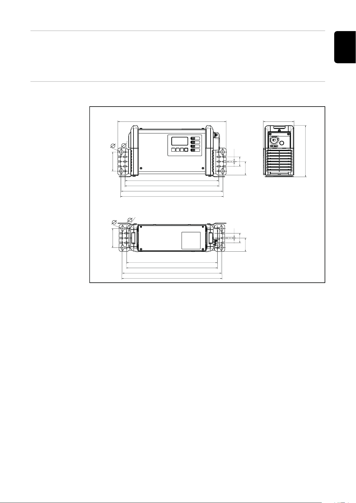
Air filter In dusty environments, the air filter prevents contamination of the inside of the
15.98 (406)
in. (mm)
B1
13.74 (349)
13.86 (352)
14.96 (380)
15.2 (386)
15.98 (339)
13.74 (342)
13.86 (370)
14.96 (376)
4.53 (115)
.26 (6,5)
1.5 (38)1.5 (38)
2.12
(53,8)
2.12
(53,8)
.26 (6,5).26 (6,5)
2.99 (76)
8.07 (205)
(2.99) 76
.55 (14)
.26 (6,5)
(.55) 14
device. This prevents any reduction in performance or other impairment of the
device. Detailed information can be found in the corresponding User Information.
Cleaning interval as required (manufacturer's recommendation: monthly)
Mounting plate The mounting plate acts as a space-saving floor or wall bracket.
EN-US
65
Page 66
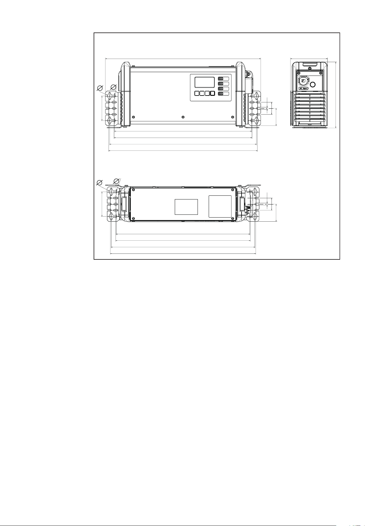
16.73 (425)
18.98 (482) 4.53 (115)
16.85 (428)
17.95 (456)
18.19 (462)
16.34 (415)
16.46 (418)
17.56 (446)
17.80 (452)
.26 (6,5)
1.5 (38)1.5 (38)
2.12
(53,8)
2.12
(53,8)
.26 (6,5).26 (6,5)
2.99 (76)
8.07 (205)
2.99 (76)
.55 (14)
.26 (6,5)
.55 (14)
in. (mm)
C1
66
Page 67
Technical data
EN-US
Selectiva 4.0 B1
UL
CAUTION!
Risk of fire.
Fire can cause serious injury and property damage.
Use only on circuits that have 20 ampere auxiliary circuit protection in ac-
▶
cordance with the National Electrical Code NFPA 70.
Mains voltage (-10 % / +10 %)
Mains frequency 60 Hz
Mains fuse protection
Minimum mains lead cross section AWG 12 (3.31 mm²)
Duty cycle 100%
Safety class I (with ground conductor)
EMC emission class B
Dimensions l x w x h 13.43 x 4.33 x 7.8 in.
Platform B1
Pollution degree 2
Degree of protection
2)
3)
1)
1~ 120 V AC / 1~ 240 V AC
max. 20 A
(341 x 110 x 198 mm)
IP21
Overvoltage category II
Operating temperature
Storage temperature -13 °F to 176 °F
Relative humidity Maximum 85%
Maximum altitude above sea level 6561 ft. (2000 m)
Mark of conformity According to rating plate
Product standard UL1564, FCC Part 15 A & B
1)
The device may be operated on grids that are grounded at the neutral
point.
2)
The leakage current to earth is less than 3.5 mA.
3)
For indoor use only, must not be exposed to rain or snow.
4)
At a high ambient temperature, a power reduction may occur (power derating).
Device-specific
data
4)
Max. AC
current
Max. AC
power
-4 °F to 104 °F
(-20 °C to +40 °C)
(-25 °C to +80 °C)
C22.2 No. 107.2-01
Max.
Nominal
voltage
charging
current Weight
5)
2040 UL 120 V
2040 UL 240 V
12.1 A
7.1 A
1530 W
1540 W
24 V 40 A 5.8 kg
(12.79 lb.)
67
Page 68
Device-specific
data
Max. AC
current
Max. AC
power
Nominal
voltage
Max.
charging
current Weight
5)
2050 UL 120 V
2050 UL 240 V
2070 UL 120 V
2070 UL 240 V
4020 UL 120 V
4020 UL 240 V
4035 UL 120 V
4035 UL 240 V
5)
With standard grid and charging cable
Device-specific
data
2040 UL 120 V
2040 UL 240 V
2050 UL 120 V
2050 UL 240 V
2070 UL 120 V
2070 UL 240 V
4020 UL 120 V
4020 UL 240 V
12.2 A
8.9 A
12.5 A
10.8 A
12.1 A
7.1 A
12.3 A
10.7 A
PF (for UAC nom, UDC nom,
IDC max)
.999
.994
.999
.997
.999
.999
.999
.994
1550 W
1920 W
1590 W
2330 W
1530 W
1520 W
1570 W
2300 W
24 V 50 A 6.1 kg
(13.45 lb.)
24 V 70 A 6.1 kg
(13.45 lb.)
48 V 20 A 5.8 kg
(12.79 lb.)
48 V 35 A 5.8 kg
(12.79 lb.)
THDi [%] (for UAC nom, U
nom, IDC max)
3.07 %
9.55 %
2.70 %
6.03 %
2.63 %
3.66 %
2.76 %
9.24 %
DC
4035 UL 120 V
4035 UL 240 V
.999
.999
2.46 %
3.56 %
68
Page 69
Selectiva 4.0 C1
UL
CAUTION!
Risk of fire.
Fire can cause serious injury and property damage.
Use only on circuits that have 20 ampere auxiliary circuit protection in ac-
▶
cordance with the National Electrical Code NFPA 70.
EN-US
Mains voltage (-10 % / +10 %)
1)
1~ 120 V AC / 1~ 240 V AC
Mains frequency 60 Hz
Mains fuse protection
2)
max. 20 A
Minimum mains lead cross section AWG 12 (3.31 mm²)
Duty cycle 100%
Safety class I (with ground conductor)
EMC emission class B
Dimensions l x w x h 16.42 x 4.33 x 7.8 in.
(417 x 110 x 198 mm)
Platform C1
Pollution degree 2
Degree of protection
3)
IP21
Overvoltage category II
Operating temperature
4)
-4 °F to 104 °F
(-20 °C to +40 °C)
Storage temperature -13 °F to 176 °F
(-25 °C to +80 °C)
Relative humidity Maximum 85%
Maximum altitude above sea level 6561 ft. (2000 m)
Mark of conformity According to rating plate
Product standard UL1564, FCC Part 15 A & B
C22.2 No. 107.2-01
1)
The device may be operated on grids that are grounded at the neutral
point.
2)
The leakage current to earth is less than 3.5 mA.
3)
For indoor use only, must not be exposed to rain or snow.
4)
At a high ambient temperature, a power reduction may occur (power derating).
Max.
Device-specific
data
2120 UL 120 V
2120 UL 240 V
4045 UL 120 V
4045 UL 240 V
Max. AC
current
15.3 A
15.4 A
14.6 A
15.1 A
Max. AC
power
2020 W
3320 W
1930 W
3250 W
Nominal
voltage
charging
current Weight
24 V 120 A 8.7 kg
(19.18 lb.)
48 V 45 A 7.4 kg
(16.31 lb.)
5)
69
Page 70
Device-specific
data
Max. AC
current
Max. AC
power
Nominal
voltage
Max.
charging
current Weight
5)
4060 UL 120 V
4060 UL 240 V
5)
With standard grid and charging cable
Device-specific
data
2120 UL 120 V
2120 UL 240 V
4045 UL 120 V
4045 UL 240 V
4060 UL 120 V
4060 UL 240 V
14.9 A
15.2 A
PF (for UAC nom, UDC nom,
IDC max)
.999
.999
.999
.999
.999
.999
1960 W
3280 W
48 V 60 A 7.4 kg
(16.31 lb.)
THDi [%] (for UAC nom, U
nom, IDC max)
2.13 %
3.04 %
1.92 %
3.15 %
1.92 %
3.04 %
DC
70
Page 71

Tabla de contenido
Rangos de potencia 73
Generalidades 73
Indicaciones de seguridad 74
General 74
Explicación de las instrucciones de seguridad 74
Condiciones ambientales 75
Acoplamiento a la red 75
Peligros originados por corriente de red y corriente de carga 75
Peligro originado por ácidos, gases y vapores 75
Indicaciones generales acerca del manejo de baterías 76
Información general sobre el uso y el mantenimiento de las conexiones de carga y los contactos
Protección personal 77
Medidas de seguridad en servicio normal 77
Clasificaciones de equipos CEM 77
Medidas de compatibilidad electromagnética (CEM) 77
Protección de datos 78
Mantenimiento 78
Reparación 78
Obligaciones de la empresa explotadora 78
Inspección de seguridad 78
Identificaciones del equipo 79
Eliminación 79
Derechos de autor 79
Indicaciones de seguridad - Necesarias para Canadá 80
Riesgos generales y eléctricos 80
Precauciones de seguridad personal 81
Preparación para la carga 81
Lugar de instalación del cargador 82
Precauciones para la conexión de CC 82
Pasos a seguir con la batería instalada en el vehículo 82
Pasos a seguir con la batería fuera del vehículo 82
Información general 83
Concepto del sistema 83
Uso previsto 83
Disposición FCC 84
Acoplamiento a la red 84
Tendido correcto de los cables de red/carga 85
Cable de carga 85
Advertencias en el equipo 86
Advertencias en el interior del sistema 87
Elección de la ubicación y montaje en la pared 88
Condiciones de emplazamiento 88
Soporte mural y fijación sobre el suelo 89
Elementos de manejo y conexiones 92
Elementos de manejo y bornas de conexión 92
Asignación de conexiones conector opcional 2 kW 94
Asignación de conexiones conector opcional 3 kW 95
Panel de control 96
Cargar la batería 98
Primera puesta en marcha 98
Iniciar el proceso de carga 100
Interrumpir el proceso de carga 102
Finalizar el proceso de carga 102
Indicación 104
Sinopsis de los modos de indicación 104
Resetear ajustes 104
Modo estándar 105
Modo estándar 105
Modo de estadística 106
ES
76
71
Page 72

Modo de estadística 106
Modo de historial 107
Modo de historial 107
Modo de configuración 109
Resumen de las opciones de ajuste en el modo de configuración 109
Acceso al modo de configuración 110
Salir del modo de configuración 111
Modo USB en el modo de configuración 112
Modo USB 112
Ajustes de carga en el modo configuración 114
Sinopsis de los ajustes de carga 114
Circulación de electrolito 114
Carga con control de temperatura 115
Carga de compensación 116
Retardo 117
Agenda 117
Cargas especiales 119
Función especial carga intermedia 120
Conexión CC 121
Funciones adicionales en el modo de configuración 122
Sinopsis de las funciones adicionales 122
Ajuste de la indicación azul "LED azul" 122
Marcha/parada externa 122
Indicación de relleno 123
Zona de opciones 123
Ajustes generales en el modo de configuración 125
Sinopsis de los ajustes generales 125
Ajustes del cable de carga 125
Limitación de corriente CA 125
Código 126
Intervalo de tiempo USB 126
Mensajes de estado 127
Mensajes de estado 127
Sinopsis de las opciones disponibles 132
Seguridad 132
Marcha/parada externa 132
Soporte mural y fijación sobre el suelo 132
Banda de LED 132
Filtro de aire 133
Placa de montaje 133
Datos técnicos 135
Selectiva 4.0 B1 UL 135
Selectiva 4.0 C1 UL 137
72
Page 73
Rangos de potencia
Generalidades La especificación de kW para los rangos de potencia hace referencia al pasamur-
os y no está directamente relacionada con la potencia real del equipo.
Para lograr una identificación clara de las versiones de la caja, se han introducido
las designaciones de plataforma B1 y C1.
Plataforma
Tensión de
batería Tipo de equipo
2040 UL 40 A
Máxima corriente
de carga
(Rango de po-
tencia) Tensión de red
ES
24 V
48 V
24 V 2120 UL 120 A
48 V
2050 UL 50 A
2070 UL 70 A
4020 UL 20 A
4035 UL 35 A
4045 UL 45 A
4060 UL 60 A
B1 (2kW)
1~ 120 V AC +/- 10 %
1~ 240 V AC +/- 10 %
C1 (3kW)
73
Page 74
Indicaciones de seguridad
General El equipo se ha fabricado según los últimos avances y la normativa de seguridad
vigente. No obstante, el manejo incorrecto o el uso inadecuado implica peligro
para:
La integridad física y la vida del operario o de terceras personas.
-
El equipo y otros bienes materiales de la empresa.
-
El trabajo eficiente con el equipo.
-
Todas las personas implicadas en la puesta en marcha, el manejo, el mantenimiento y la conservación del equipo deben:
Poseer la cualificación correspondiente.
-
Leer completamente y seguir exhaustivamente este manual de instrucciones.
-
El manual de instrucciones debe permanecer guardado en el lugar de empleo del
equipo. Además de este manual de instrucciones, se deben tener en cuenta la
normativa general vigente y la normativa local en materia de prevención de accidentes y protección medioambiental.
Todas las instrucciones de seguridad y peligro en el equipo:
deben mantenerse en estado legible,
-
no deben dañarse
-
ni retirarse
-
No se deben tapar ni cubrir con pegamento o pintura.
-
Explicación de
las instrucciones
de seguridad
Las posiciones de las instrucciones de seguridad y peligro en el equipo figuran en
el capítulo "Información general" del manual de instrucciones.
Cualquier error que pueda afectar a la seguridad debe solucionarse antes de
conectar el equipo.
¡Es por su seguridad!
¡ADVERTENCIA!
Indica un peligro inminente.
En caso de no evitar el peligro, las consecuencias pueden ser la muerte o le-
▶
siones de carácter muy grave.
¡PELIGRO!
Indica una situación posiblemente peligrosa.
Si no se evita esta situación, se puede producir la muerte así como lesiones
▶
de carácter muy grave.
¡PRECAUCIÓN!
74
Indica una situación posiblemente perjudicial.
Si no se evita esta situación, se pueden producir lesiones de carácter leve o
▶
de poca importancia, así como daños materiales.
¡OBSERVACIÓN!
Indica la posibilidad de obtener unos resultados mermados de trabajo y que se
puedan producir daños en el equipamiento.
Page 75

Condiciones ambientales
Cualquier servicio o almacenamiento del equipo fuera del área indicada será considerado como no previsto. El fabricante declina cualquier responsabilidad frente
a los daños que se pudieran originar.
El capítulo "Datos técnicos" proporciona información detallada acerca de las
condiciones ambientales admisibles.
ES
Acoplamiento a
la red
Peligros originados por corriente
de red y corriente de carga
Por su consumo de corriente, los equipos de alta potencia pueden repercutir
sobre la calidad de energía de la red.
Esta característica puede afectar a algunos tipos de equipos y manifestarse de
las siguientes formas:
Limitaciones en la conexión, requisitos relativos a la impedancia de la red
-
máxima *); o bien
-
Requisitos con respecto a la mínima potencia de cortocircuito necesaria
*)
.
*)
En cada caso en el interface a la red pública
Ver los datos técnicos
En este caso, la empresa explotadora o el usuario del equipo deben asegurar que
la conexión del equipo esté permitida y, si fuera necesario, deben consultar el
caso con la correspondiente empresa suministradora de energía.
¡IMPORTANTE! ¡Prestar atención a que la puesta a tierra del acoplamiento a la
red sea segura!
Los trabajos con cargadores suponen la exposición a múltiples peligros como, por
ejemplo:
Peligro eléctrico originado por corriente de red y corriente de carga.
-
Campos electromagnéticos perjudiciales que pueden suponer un peligro
-
mortal para personas con marcapasos.
Peligro originado
por ácidos, gases
y vapores
Las descargas eléctricas pueden ser mortales. Cualquier descarga eléctrica
supone, en principio, un peligro mortal. A fin de evitar descargas eléctricas durante el funcionamiento, se debe tener en cuenta lo siguiente:
No entrar en contacto con piezas bajo tensión dentro y fuera del equipo.
-
En ningún caso entrar en contacto con los polos de la batería.
-
No cortocircuitar el cable de carga ni los bornes de carga.
-
Todos los cables y líneas deben estar fijados, intactos, aislados y tener una dimensión suficiente. Las uniones sueltas y los cables y líneas chamuscados,
dañados o con una dimensión insuficiente deben repararse inmediatamente en
un taller especializado autorizado.
Las baterías contienen ácidos dañinos para los ojos y la piel. Además, al cargar
las baterías se generan gases y vapores que pueden dañar la salud y que son altamente explosivos en determinadas circunstancias.
Utilizar el cargador exclusivamente en locales con buena ventilación a fin de
evitar la acumulación de gases explosivos. Los locales de almacenamiento de
baterías se consideran como no sujetos a riesgo de explosión cuando la vent-
75
Page 76

ilación natural o técnica garantiza una concentración de hidrógeno inferior al
4 %.
Durante la carga se debe mantener una distancia mínima de 0,5 m (19.69 in.)
entre la batería y el cargador. Se deben mantener alejadas de la batería las posibles fuentes de chispas, fuego y luz desprotegida.
En ningún caso se debe desembornar la unión a la batería (por ejemplo, bornes
de carga) durante el proceso de carga.
En ningún caso se deben inhalar los gases y vapores que se van generando. Es imprescindible garantizar una ventilación suficiente.
No colocar herramientas o metales con conductividad eléctrica sobre la batería
para evitar cortocircuitos.
El ácido de la batería no debe entrar bajo ningún concepto en contacto con los
ojos, la piel o la ropa. Llevar gafas de protección y ropa adecuada. Lavar inmediatamente y con abundante agua las proyecciones de ácido; si fuera necesario,
acudir al médico.
Indicaciones
generales acerca
del manejo de
baterías
Información
general sobre el
uso y el mantenimiento de las
conexiones de
carga y los contactos
Proteger las baterías frente a la suciedad y daños mecánicos.
-
Almacenar las baterías cargadas en locales fríos. La menor descarga es-
-
pontánea se produce a una temperatura de aproximadamente +2 °C (35.6
°F).
Asegurarse de que la batería se ha llenado hasta la marca máxima con ácido
-
(electrolito), siguiendo las indicaciones de fabricante de la batería o mediante
una comprobación visual realizada al menos una vez por semana.
En los siguientes casos no se debe iniciar o se debe interrumpir inmediata-
-
mente el servicio del equipo y encomendar la comprobación de la batería a
un taller especializado autorizado:
Nivel de ácido irregular o consumo elevado de agua en diferentes celdas
-
a causa de un posible defecto.
Calentamiento inadmisible de la batería a temperaturas superiores a 55
-
°C (131 °F).
Las conexiones de carga se desgastan cuando se enchufan y desenchufan con
frecuencia. Por ello, se consideran piezas de mantenimiento en combinación con
los cables de alimentación conectados.
Se recomienda el uso de una conexión (clavija + enchufe) del mismo fabricante.
Antes de cada carga, el usuario debe comprobar que ambos lados de la conexión
no estén dañados ni sucios.
En el caso de que se combinen conexiones de diferentes fabricantes, se debe
tener especial cuidado durante la inspección.
Las diferentes tolerancias en la forma y la geometría de las conexiones de los distintos fabricantes pueden provocar un mayor desgaste.
El aumento del desgaste afecta negativamente a las resistencias de transición,
así como las fuerzas de inserción, tiro y sujeción.
76
En caso de daños, las piezas afectadas deben reemplazarse inmediatamente.
El operador debe descartar el uso posterior de las mitades de conexión dañadas.
La suciedad debe eliminarse.
En el marco de la inspección anual, el servicio técnico o el personal correspondiente también deberá examinar las mitades de conexión y los cables de alimentación.
En caso de aumento de la carga (p. ej. perfil de corriente, aumento de la suciedad
Page 77

o de la temperatura ambiente), se debe comprobar si es necesario que el operador realice un cambio de forma prematura.
Protección personal
Medidas de seguridad en servicio normal
Las personas, especialmente los niños, deben mantenerse alejadas de la zona de
trabajo durante el servicio del equipo. Si aún así hay personas cerca:
Instruir a las mismas acerca de los peligros (ácidos y gases perjudiciales para
-
la salud, riesgo originado por corriente de red y corriente de carga...).
Poner a disposición medios adecuados de protección.
-
Antes de abandonar la zona de trabajo, asegurarse de que no se puedan producir
daños personales o materiales durante la ausencia.
Los equipos con conductor protector deben utilizarse solo en una red preparada
para ello y en un enchufe con un contacto de conductor protector. Se considerará negligencia grave la utilización del equipo en una red sin conductor protector
o en un enchufe que carezca de contacto de conductor protector. El fabricante
declina cualquier responsabilidad frente a los daños que se pudieran originar.
Utilizar el equipo solo según el tipo de protección indicado en la placa de características.
En ningún caso se debe poner el equipo en servicio cuando presente daños.
Un electricista especializado debe comprobar periódicamente la alimentación de
red respecto a la capacidad de funcionamiento del conductor protector.
Los dispositivos de seguridad que no dispongan de plena capacidad de funcionamiento y los componentes que no se encuentren en perfecto estado antes
de la conexión del aparato deben ser reparados por un taller especializado autorizado.
ES
Clasificaciones
de equipos CEM
Medidas de compatibilidad electromagnética
(CEM)
Los dispositivos de protección no se deben anular ni poner fuera de servicio.
Después del montaje se requiere una clavija para la red de acceso libre.
Equipos de la clase de emisión A:
Solo están destinados al uso en zonas industriales.
-
Pueden provocar perturbaciones condicionadas a la línea e irradiadas en
-
otras regiones.
Equipos de la clase de emisión B:
Cumplen los requisitos de emisión en zonas residenciales e industriales. Lo
-
mismo es aplicable a zonas residenciales en las que la energía se suministra
desde una red de baja tensión pública.
Clasificación de equipos CEM según la placa de características o los datos técnicos.
En casos especiales puede ocurrir que, a pesar de cumplirse los valores límite de
emisión normalizados, se produzcan influencias para el campo de aplicaciones
previsto (por ejemplo, cuando hay aparatos sensibles en el lugar de emplazamiento o cuando el lugar de emplazamiento está cerca de receptores de radio o
televisión).
77
Page 78

En estos casos, el empresario está obligado a aplicar las medidas adecuadas para
eliminar las perturbaciones.
Protección de
datos
Mantenimiento Antes de cada puesta en marcha, comprobar que la clavija, el cable de red, los
Reparación Los trabajos de reparación deben ser efectuados exclusivamente por un taller es-
El usuario es responsable de la salvaguardia de datos de las modificaciones
frente a los ajustes de fábrica. El fabricante no es responsable en caso de que se
borren los ajustes personales.
cables de carga y los bornes de carga no estén dañados.
En caso de que haya suciedad, se debe limpiar la superficie de la caja del equipo
con un paño suave y utilizar exclusivamente agentes de limpieza que no tengan
disolventes.
pecializado autorizado. Utilizar solo repuestos y piezas de desgaste originales (lo
mismo rige para piezas normalizadas). En caso de piezas procedentes de otros
fabricantes, no queda garantizado que hayan sido diseñadas y fabricadas de
acuerdo con las exigencias en cuanto a resistencia y seguridad.
Los cambios, montajes o transformaciones en el equipo solo están permitidos
con previa autorización del fabricante.
Obligaciones de
la empresa explotadora
Inspección de
seguridad
La empresa explotadora se compromete a que solo trabajen con el equipo personas que:
Estén familiarizadas con las prescripciones fundamentales en relación con la
-
seguridad laboral y la prevención de accidentes y que hayan sido instruidas
en el manejo del equipo.
Hayan leído y comprendido en particular el capítulo "Normas de seguridad"
-
en el presente manual de instrucciones, confirmando la lectura y comprensión mediante su firma.
Hayan recibido la formación necesaria en relación con los requisitos de los
-
resultados de trabajo.
Se debe comprobar periódicamente que el personal trabaja de forma segura.
El fabricante recomienda encomendar, al menos cada 12 meses, una inspección
de seguridad.
Únicamente un especialista eléctrico capacitado puede llevar a cabo la inspección de seguridad necesaria
tras cualquier cambio,
-
tras montajes o transformaciones,
-
tras la reparación, el cuidado y el mantenimiento,
-
al menos cada 12 meses.
-
78
Para la inspección de seguridad se deben observar las normas y directivas
nacionales e internacionales.
El centro de servicio correspondiente le proporcionará información más detallada acerca de la inspección de seguridad. Bajo demanda, también le proporcionará la documentación necesaria.
Page 79

Identificaciones
del equipo
Los equipos con la declaración de conformidad CSA cumplen los requisitos fundamentales de las directivas pertinentes.
Eliminación Los residuos de equipos eléctricos y electrónicos deben desecharse por separado
y reciclarse de forma respetuosa con el medio ambiente de acuerdo con la directiva de la Unión Europea y la legislación nacional. Los equipos usados deben
devolverse al distribuidor o desecharse a través de un sistema de eliminación y
recogida local autorizado. La eliminación adecuada del equipo usado fomenta el
reciclaje sostenible de los recursos materiales. Ignorarlo puede tener efectos
negativos sobre la salud y el medio ambiente.
Materiales del embalaje
Recogida por separado. Consulta la normativa de tu municipio. Reduce el volumen de la caja.
Derechos de
autor
Los derechos de autor respecto al presente manual de instrucciones son
propiedad del fabricante.
El texto y las ilustraciones contienen información actualizada en el momento de
la impresión. Reservado el derecho a modificaciones. El contenido del manual de
instrucciones no justifica ningún tipo de derecho por parte del comprador.
Agradecemos cualquier propuesta de mejora e indicaciones respecto a errores en
el manual de instrucciones.
ES
79
Page 80
Indicaciones de seguridad - Necesarias para
Canadá
Riesgos generales y eléctricos
CONSERVE CUIDADOSAMENTE ESTAS INSTRUCCIONES - Esta guía con-
1
tiene importantes instrucciones de seguridad y funcionamiento para estos tipos de cargadores (para el modelo, véase la primera página de este documento).
No exponga el cargador a la lluvia o a la nieve.
2
El uso de accesorios no vendidos o recomendados por el fabricante del car-
3
gador puede provocar un incendio, una descarga eléctrica o lesiones personales.
Para reducir el riesgo de dañar los enchufes y los cables, desenchufe siempre
4
el cargador tirando del enchufe y no del cable.
El uso de un adaptador no está permitido en Canadá. Si no se dispone de una
5
toma de corriente con conexión a tierra, no utilice este aparato hasta que un
electricista cualificado instale la toma de corriente adecuada.
Utilice un cable alargador sólo si es absolutamente necesario. El uso de un
6
cable alargador incorrecto puede provocar un incendio y una descarga
eléctrica. Si es necesario utilizar un cable alargador, asegúrese de que
las clavijas del enchufe del cable alargador son del mismo número,
-
tamaño y forma que las del enchufe del cargador
el cable de extensión está correctamente cableado y en buenas condi-
-
ciones eléctricas
el tamaño del cable es lo suficientemente grande para el amperaje de CA
-
del cargador, como se ha indicado anteriormente
Tamaño mínimo de AWG de un cable de extensión para el acoplamiento a la red
2040 UL 2050 UL 2070 UL 2120 UL
25 ft (7.6 m) AWG 12 AWG 12 AWG 12 AWG 12
50 ft (15.2 m) AWG 12 AWG 12 AWG 12 AWG 12
75 ft (22.9 m) AWG 12 AWG 12 AWG 12 AWG 12
100 ft (30.5 m) AWG 12 AWG 12 AWG 12 AWG 10
125 ft (38.1 m) AWG 10 AWG 10 AWG 10 AWG 10
150 ft (45.7 m) AWG 10 AWG 10 AWG 10 AWG 8
Tamaño mínimo de AWG de un cable de extensión para el acoplamiento a la red
4035 UL 4020 UL 4045 UL 4060 UL
25 ft (7.6 m) AWG 12 AWG 12 AWG 12 AWG 12
50 ft (15.2 m) AWG 12 AWG 12 AWG 12 AWG 12
75 ft (22.9 m) AWG 12 AWG 12 AWG 12 AWG 12
100 ft (30.5 m) AWG 12 AWG 12 AWG 10 AWG 10
125 ft (38.1 m) AWG 10 AWG 10 AWG 10 AWG 10
150 ft (45.7 m) AWG 10 AWG 10 AWG 8 AWG 8
80
No utilice el cargador con un cable o un enchufe dañado: sustituya el cable o
7
el enchufe inmediatamente.
No utilice el cargador si se ha sometido a un fuerte impacto, se ha caído o se
8
ha dañado de alguna manera; entréguelo a un técnico cualificado.
Page 81
No desmonte el cargador; entréguelo a un técnico cualificado en caso de ne-
9
cesitar mantenimiento o reparación. Un montaje incorrecto puede provocar
un incendio o una descarga eléctrica.
Para reducir el riesgo de descarga eléctrica, desenchufe el cargador de la
10
toma de corriente antes de realizar cualquier operación de mantenimiento o
limpieza. Este riesgo no puede reducirse colocando los controles en la
posición "Off".
ES
Precauciones de
seguridad personal
Debe haber otra persona al alcance de su oído o lo suficientemente cerca como
para acudir en su ayuda cuando esté trabajando cerca de una batería.
Asegúrese de que hay suficiente agua fresca y jabón cerca en caso de que el
1
electrolito entre en contacto con la piel, la ropa o los ojos.
Se debe utilizar una protección completa para los ojos y ropa de protección.
2
No se toque los ojos cuando trabaje cerca de una batería.
Si la piel o la ropa entran en contacto con el electrolito, lávese inmediata-
3
mente con agua y jabón. Si el electrolito entra en contacto con los ojos, enjuáguelos inmediatamente con agua fría durante al menos 10 minutos y solicite asistencia médica inmediata.
NUNCA fume ni permita que haya una chispa o llama abierta cerca de la
4
batería.
Tenga especial cuidado para evitar el riesgo de que una herramienta metálica
5
caiga sobre la batería. Esto podría crear chispas o cortocircuitar la batería u
otros componentes eléctricos, provocando así una explosión.
Quítese los objetos metálicos personales como anillos, pulseras, collares y
6
relojes antes de trabajar con una batería. Una batería puede provocar una
corriente de cortocircuito lo suficientemente alta como para fundir un anillo
o similar, provocando así un incendio.
Utilice el cargador únicamente para cargar una batería destinada a este fin.
7
No está diseñado para suministrar energía a un sistema eléctrico de muy bajo
voltaje ni para cargar baterías de pila seca. La carga de baterías de pila seca
puede hacer que éstas estallen y causen lesiones a las personas y daños a la
propiedad.
Preparación para
la carga
Si es necesario retirar la batería del vehículo para cargarla, retire siempre
1
primero el terminal de tierra de la batería. Asegúrese de que todos los accesorios del vehículo están apagados para evitar un arco eléctrico.
Asegúrese de que el área alrededor de la batería esté bien ventilada mientras
2
se está cargando la batería. El gas liberado puede dispersarse eficazmente
utilizando un trozo de cartón u otro objeto no metálico, como un ventilador.
Limpie los terminales de la batería. Tenga cuidado de que los residuos de cor-
3
rosión no entren en contacto con los ojos.
Siga cuidadosamente las instrucciones de carga del fabricante.
4
Estudie todas las precauciones específicas del fabricante de la batería, como
5
las tasas de carga recomendadas.
Con la ayuda del manual del vehículo, determine la tensión de la batería y
6
asegúrese de que coincide con la salida del cargador.
En el caso de un cargador que tenga un interruptor selector de tensión de
7
salida, consulte el manual del propietario del vehículo para determinar la
tensión de la batería y asegurarse de que la tensión de salida está ajustada a
la tensión correcta. Si no se dispone de un interruptor selector de tensión de
salida, no utilice el cargador de baterías a menos que la tensión de la batería
coincida con la tensión de salida del cargador.
81
Page 82
Lugar de instalación del
cargador
Nunca coloque el cargador directamente encima o debajo de la batería que
1
se está cargando. Los gases o fluidos de la batería corroerán y dañarán el cargador. Coloque el cargador tan lejos de la batería como lo permitan los cables
de CC.
No utilice el cargador en un área cerrada ni restrinja la ventilación de ninguna
2
manera.
No coloque la batería en el cargador.
3
Precauciones
para la conexión
de CC
Pasos a seguir
con la batería instalada en el
vehículo
Conecte y desconecte los enchufes de CC sólo después de poner los inter-
1
ruptores del cargador en la posición de apagado y de retirar el cable de CA
de la toma de corriente. Nunca permita que los enchufes de CC se toquen
entre sí.
Siga estos pasos cuando la batería esté instalada en el vehículo. Una chispa cerca
de la batería puede provocar una explosión de la misma. Para reducir el riesgo de
una chispa cerca de la batería:
Coloque los cables de CA y CC para reducir el riesgo de daños en las piezas
1
móviles.
Aléjese de las aspas del ventilador, las correas, las poleas y otras piezas que
2
puedan causar lesiones a las personas.
Conecte los enchufes de CC manteniéndolos lo más alejados posible de la
3
batería.
Conecte el cable de alimentación de CA del cargador a la toma de corriente.
4
Al desconectar el cargador, ponga los interruptores en posición de apagado,
5
desconecte el cable de CA y, a continuación, desconecte los enchufes de CC.
Para obtener información sobre el periodo de carga necesario, consulte las
6
instrucciones de uso.
Pasos a seguir
con la batería
fuera del
vehículo
Siga estos pasos cuando la batería esté fuera del vehículo. Una chispa cerca de la
batería puede provocar una explosión de la misma. Para reducir el riesgo de una
chispa cerca de la batería:
No mire hacia la batería cuando haga la conexión final.
1
Conecte los enchufes de CC manteniéndolos lo más alejados posible de la
2
batería.
Conecte el cable de suministro de CA del cargador a la toma de corriente.
3
Al desconectar el cargador, hágalo siempre en la secuencia inversa al pro-
4
cedimiento de conexión y rompa la primera conexión estando lo más lejos
posible de la batería.
La batería de un barco (marino) debe sacarse y cargarse en tierra firme. La
5
carga de la batería a bordo requiere un equipo especial diseñado para su uso
en el mar.
82
Page 83
Información general
Concepto del
sistema
Uso previsto El cargador sirve para cargar las baterías indicadas a continuación. Cualquier otro
Los cargadores monofásicos para baterías de 24 V y 48 V se caracterizan por su
inteligente tecnología de carga. La Active Inverter Technology con el proceso de
carga Ri se adapta a las necesidades de la batería, cargándola con corriente solo
cuando realmente es necesario.
La tecnología se encuentra encastrada en una carcasa robusta según estándar industrial. El diseño compacto cumple con todas las exigencias marcadas por los
estándares de seguridad, reduce las necesidades de espacio y protege los componentes para garantizar así una larga vida útil.
El equipo incluye pantalla gráfica, un Datalogger integrado, nuevos interfaces y
opciones adicionales, estando perfectamente preparado para el futuro.
uso se considera no previsto. El fabricante declina cualquier responsabilidad
frente a los daños que se pudieran originar. Se considera también uso previsto:
El cumplimiento de las observaciones del manual de instrucciones.
-
La comprobación periódica de los cables de red y carga.
-
¡PELIGRO!
Peligro originado por la carga de baterías secas (elementos primarios) y baterías
no recargables.
La consecuencia pueden ser graves daños personales y materiales debidos a fugas de la batería.
Cargar únicamente los tipos de batería indicados a continuación.
▶
ES
¡PELIGRO!
Peligro por cargar baterías inadecuadas.
La consecuencia pueden ser graves daños personales y materiales debido a la fuga de gases, inflamación o explosión.
Conectar únicamente baterías al cargador cuyo tipo, tensión y capacidad
▶
sean adecuados para el cargador y cumplan con los ajustes del cargador.
El cargador está pensado para la carga de baterías de ácido-plomo y baterías
NiCd:
Baterías Pb-WET (PzS, GiS, ...):
-
Baterías húmedas de ácido-plomo selladas con electrolito líquido.
Baterías Pb-GEL (PzV, GiV, ...):
-
Baterías de ácido-plomo cerradas y reguladas con válvulas (VRLA) con electrolito sólido (gel o vello).
Baterías AGV (LFP-fosfato de litio y hierro, ...)
-
Baterías NiCd:
-
Baterías NiCd cerradas con electrolito líquido.
Baterías Pb-CSM-WET (Copper Strained Metal):
-
Baterías CSM de ácido-plomo cerradas con electrolito líquido.
Baterías PZQ
-
Baterías de cristal de plomo:
-
Baterías de cristal de plomo de tipo EVFJ/CNFJ.
83
Page 84
El funcionamiento correcto del equipo depende de su manejo. En ningún caso
debe tirarse del cable al manejar el equipo.
Disposición FCC
Acoplamiento a
la red
FCC
Este equipo ha sido verificado y cumple los valores límite de un equipo digital de
la clase B según la parte 15 de las disposiciones FCC. Estos valores límite pretenden garantizar una protección adecuada frente a perturbaciones en espacios
residenciales. Este equipo genera y utiliza energía de alta frecuencia y puede provocar incidencias en la radiocomunicación cuando no es utilizado de acuerdo con
las instrucciones. No obstante, no puede garantizarse la ausencia de incidencias
en una determinada instalación.
Si este equipo produce incidencias en la recepción de radio o televisión que
pueden detectarse apagando y volviendo a encender el equipo, se recomienda al
usuario eliminar las incidencias aplicando una o varias de las siguientes medidas:
Alinear o cambiar el posicionamiento de la antena receptora.
-
Incrementar la distancia entre el equipo y el receptor.
-
Conectar el equipo a otro circuito de corriente al que no está conectado el
-
receptor.
Para más ayuda rogamos que se ponga en contacto con el distribuidor o un
-
técnico experimentado en radio y televisión.
¡PELIGRO!
Peligro originado por corriente eléctrica.
La consecuencia pueden ser lesiones de carácter grave o la muerte.
Se deben apagar y separar de la red de corriente todos los equipos y com-
▶
ponentes antes de comenzar los trabajos.
Asegurar todos los equipos y componentes contra cualquier reconexión.
▶
¡PELIGRO!
Peligro originado por un manejo incorrecto y trabajos realizados incorrectamente.
Esto puede ocasionar lesiones personales graves y daños materiales.
Todos los trabajos y funciones descritos en este documento deben ser realiz-
▶
ados solo por personal técnico formado.
Leer y entender este documento.
▶
Leer y entender todos los manuales de instrucciones de los componentes del
▶
sistema, en particular las normas de seguridad.
¡PELIGRO!
Peligro originado por una alimentación de red defectuosa o inapropiada.
Esto puede ocasionar lesiones personales graves y daños materiales.
Se deben cumplir las exigencias relativas a la alimentación de red según el
▶
capítulo "Datos técnicos".
84
Page 85
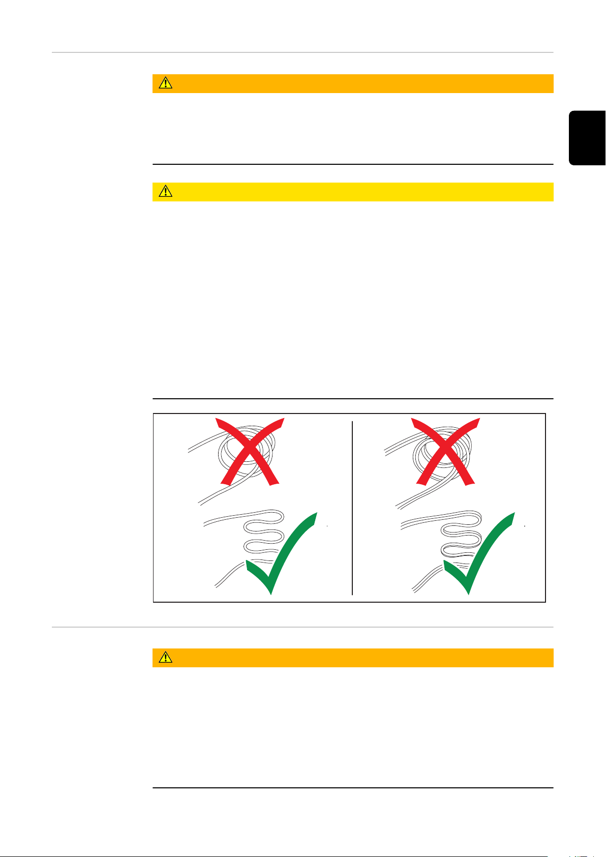
Tendido correcto
de los cables de
red/carga
¡PELIGRO!
Peligro originado por cables de carga sueltos.
La consecuencia pueden ser graves daños personales y materiales. Las personas
se pueden quedar enganchadas o tropezar con los cables estirados o sueltos.
Instalar los cables de carga de tal modo que nadie pueda tropezar o
▶
quedarse enganchado en ellos.
¡PRECAUCIÓN!
Riesgo derivado de un calentamiento excesivo por cables de red/carga tendidos
incorrectamente.
Riesgo de daños en los cables de alimentación/carga.
El cambio del cable de alimentación/carga solo puede realizarlo un electri-
▶
cista cualificado.
Instalar el cable de red/carga sin que se formen bucles.
▶
No cubrir el cable de red/carga.
▶
Los cables de carga de más de 16 ft. 4.85 in. (5 m) de longitud se deben in-
▶
stalar individualmente (no se pueden agrupar).
Los cables de carga de más de 16 ft. 4.85 in. (5 m) de longitud pueden
▶
presentar una mayor temperatura superficial (atención a las superficies calientes).
En los siguientes casos, procurar que la temperatura de la superficie de los
▶
cables de carga no supere los 176 °F (80 °C):
- Si la temperatura ambiente es de 86 °F (30 °C) o más
ES
Cable de carga
¡PELIGRO!
Peligro de proyección de chispas debido a la desconexión incorrecta del enchufe
de carga.
La consecuencia pueden ser graves daños personales y materiales. Las chispas
que se producen en este proceso pueden encender los gases de carga que se
forman durante el proceso de carga y como consecuencia provocar un incendio o
una explosión.
Finalizar el proceso de carga a través del cargador y, una vez que los cables
▶
de carga se hayan enfriado, enrollarlos o colocarlos en el soporte para cables
si se dispone de uno.
85
Page 86
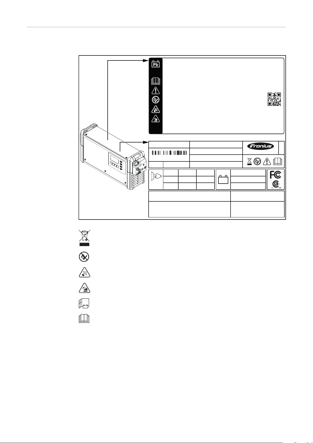
Advertencias en
Protective class I
Production Date Code
UAC nom.
UDC nom.
IDC max.
Part No.:
Ser. No.:
IAC max.
PAC max.
PDC nom.
240VAC
xxAxxA
xxxxWxxxxW
xxV
xxA
xxW
1~ NPE
60Hz
IP21 Platform x1
This device complies with Part 15 of the FCC Rules.
Operation is subject to the following two conditions:
(1) This device may not cause harmful interference, and
(2) This device must accept any interference received,
including interference that may cause undesired operation.
CAN ICES-001 (B) / NMB-001 (B)
Fronius International GmbH
Froniusstraße 1
A-4643 Pettenbach
Austria
DANGER
Risk of electric shock. Do not touch uninsulated portion
of output connector or uninsulated battery terminal.
120VAC
www.fronius.com
XXXX
xxxxxxxx
xxxx
xxxxxxxx
xxxxxxxx
Selectiva 4.0 xxxx xkW UL
Warning
High leakage current!
Earth connection essential before connecting supply.
Always stop charging before you disconnect the charging cable!
Explosive gases. Prevent flames and sparks.
Provide adequate ventilation during charge!
Avertissement
Fuite élevée de courant!
Raccordement á la terre indispensable avant le raccordement au réseau.
Toujours arrêter la charge avant de déconnecter le câble de charge!
Gaz explosifs. Éviter les flames et les étincelles.
Prévoir une ventilation adaptée pendant la charge!
42,0409,1321
el equipo
El cargador de batería incluye símbolos de seguridad. Estos símbolos no se deben
quitar ni cubrir con pintura.
86
Los equipos usados no deben arrojarse a la basura doméstica. Deben
desecharse siguiendo las normas de seguridad que se apliquen en cada
lugar.
Se deben mantener alejadas de la batería las posibles fuentes de chispas, fuego y luz.
¡Peligro de explosión! Debido a la carga se genera gas detonante en la
batería.
El ácido de la batería es cáustico y en ningún caso debe entrar en contacto con los ojos, la piel o la ropa.
Durante la carga se debe proporcionar suficiente alimentación de aire
fresco.
Utilizar las funciones solo después de haber leído por completo el
manual de instrucciones.
Page 87
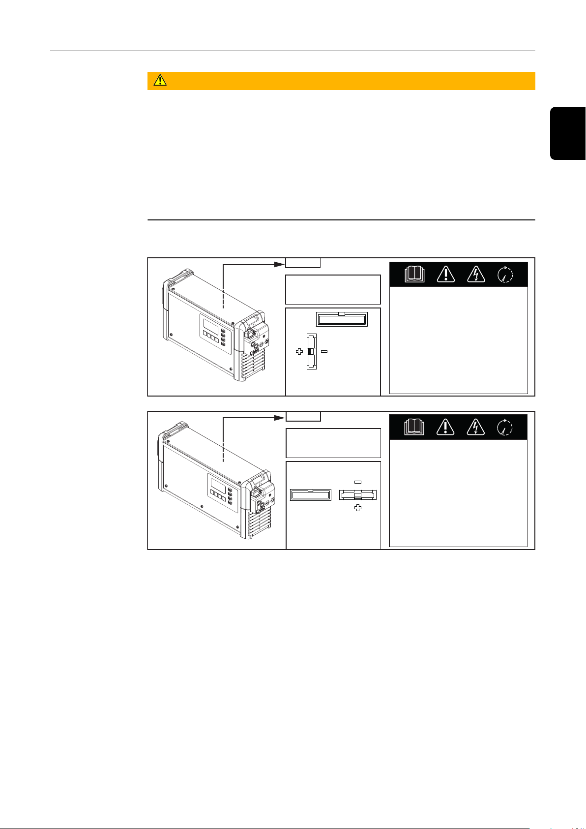
Advertencias en
B1
4,010,xxx
xxxxxxxx
XXXX
UDC nom. xxV
Part No.:
Ser. No.:
1
2
1 Display
2 Battery CR2032
WARNING Hazardous Voltage
Kondensator Entladezeit < 2 min.
Capacitor discharge time < 2 min.
Décharge de condensateur < 2 min.
Condensador tiempo de descarga < 2 min.
Condensatore tempo di scaricamento < 2 min.
C1
4,010,xxx
xxxxxxxx
XXXX
UDC nom. xxV
Part No.:
Ser. No.:
1
2
1 Display
2 Battery CR2032
WARNING Hazardous Voltage
Kondensator Entladezeit < 2 min.
Capacitor discharge time < 2 min.
Décharge de condensateur < 2 min.
Condensador tiempo de descarga < 2 min.
Condensatore tempo di scaricamento < 2 min.
el interior del
sistema
¡PELIGRO!
Peligro originado por descarga eléctrica
La consecuencia pueden ser lesiones de carácter grave o la muerte.
Solo los técnicos de servicio formados por el fabricante deben abrir la caja.
▶
Antes de realizar trabajos con la caja abierta debe separarse el equipo de la
▶
red. Con un aparato de medición adecuado, asegurarse de que los componentes con carga eléctrica (por ejemplo, condensadores) estén completamente descargados.
Con la ayuda de un rótulo de aviso claro y legible, asegurarse de que el
▶
equipo permanezca separado de la red hasta que se hayan finalizado todos
los trabajos.
En el interior del sistema:
ES
87
Page 88
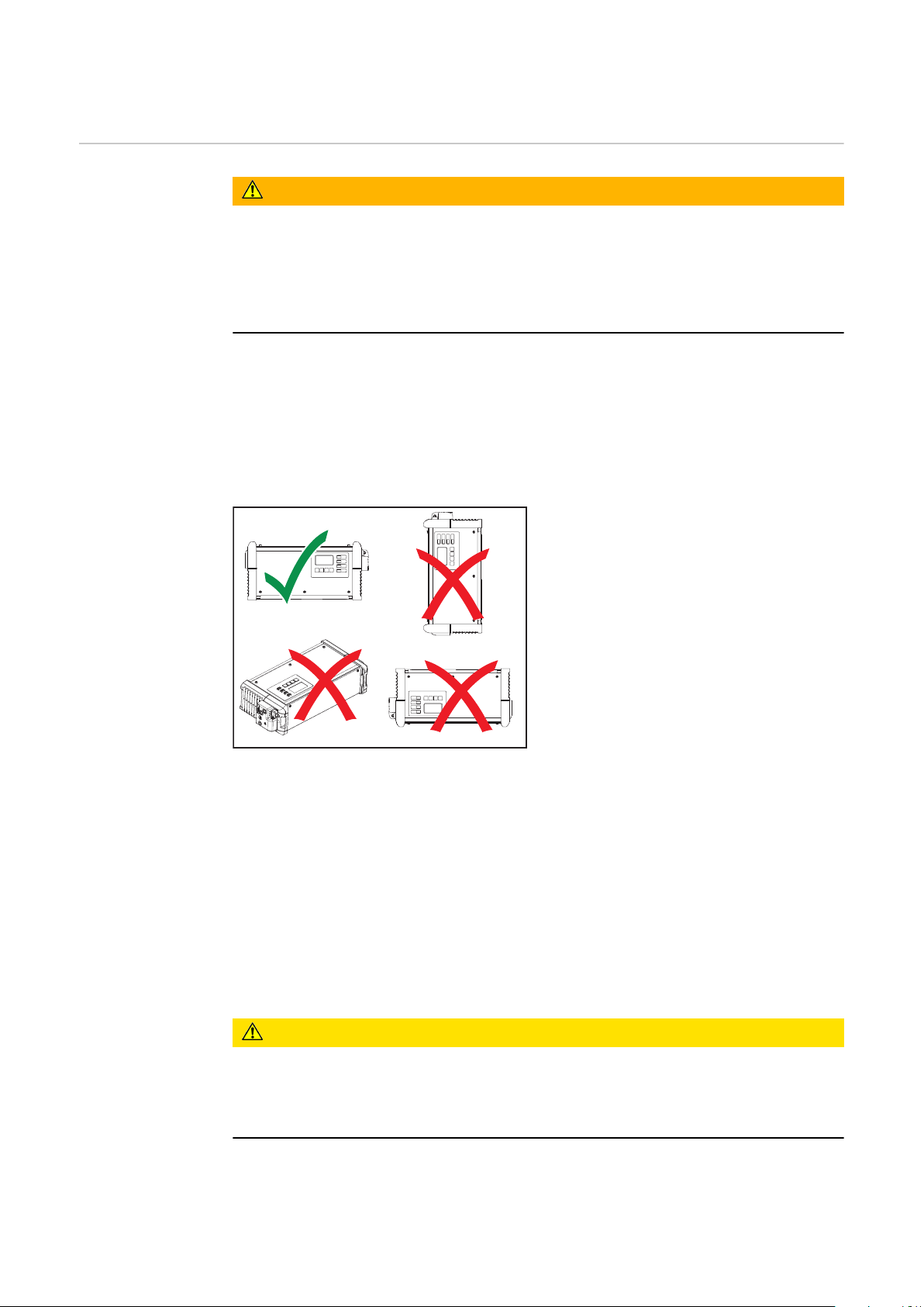
Elección de la ubicación y montaje en la pared
Condiciones de
emplazamiento
¡PELIGRO!
Riesgo derivado de la caída o el vuelco de equipos.
La consecuencia pueden ser graves daños personales y materiales.
Emplazar todos los componentes del sistema de forma que no puedan
▶
caerse.
En caso de utilizar una fijación sobre el suelo o un soporte mural, debe ase-
▶
gurarse siempre el asiento firme de todos los elementos de fijación.
El equipo está homologado según el tipo de protección IP21, lo que significa:
Protección frente a la penetración de cuerpos extraños sólidos con un
-
diámetro de más de .49 in. (12,5 mm)
Protección contra goteo de agua de caída vertical
-
El equipo puede colocarse y utilizarse en locales secos cerrados según el tipo de
protección IP21. Se debe evitar cualquier acción de la humedad.
Los equipos deben utilizarse en horizontal.
Aire de refrigeración
Se debe colocar el equipo de tal modo que el aire de refrigeración pueda pasar
libremente por las aberturas previstas en la caja. Siempre debe existir una distancia mínima de 7.87 in. (20 cm) con respecto a las entradas y salidas de aire. El
aire ambiental debe estar libre de:
Carga de polvo excesivamente intensa
-
Partículas con conductividad eléctrica (hollín o virutas metálicas)
-
Fuentes de calor
-
Vapores de ácido de la batería
-
La aspiración y la salida del aire de refrigeración se realizan según los símbolos
de flecha en las siguientes ilustraciones.
¡PRECAUCIÓN!
Riesgo derivado de entradas y salidas de aire parcial o completamente tapadas.
Pueden producirse daños materiales.
Si se colocan varios equipos unos detrás de otros, debe dejarse cierta distan-
▶
cia entre ellos.
88
Page 89
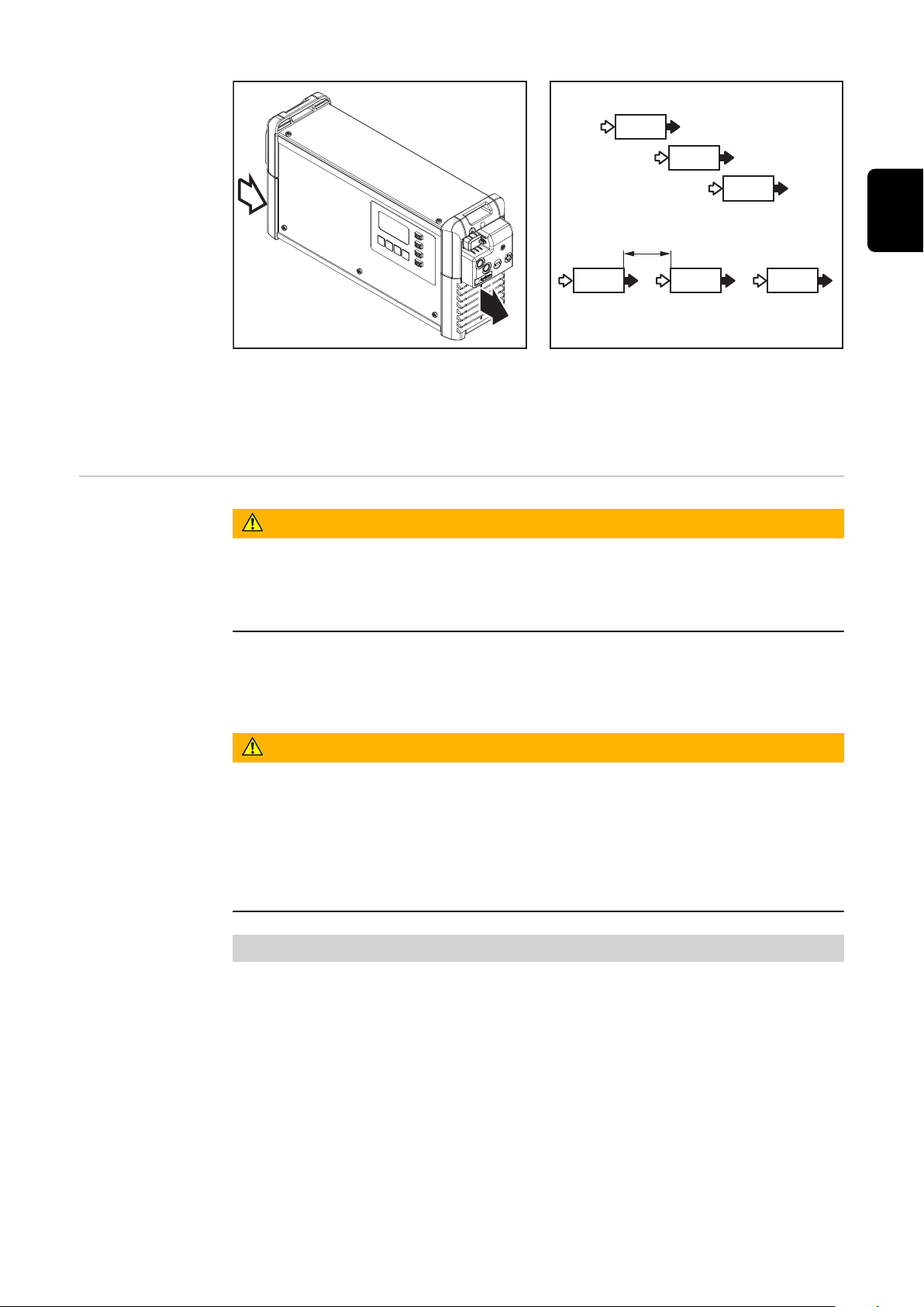
(a)
Si no hay ningún desplazamiento entre los equipos colocados en fila uno tras
otro, la distancia entre los equipos debe estar dimensionada de la siguiente manera:
Distancia mínima 7.87 in. (20 cm)
a)
ES
Soporte mural y
fijación sobre el
suelo
¡PELIGRO!
Peligro originado por trabajos realizados de forma incorrecta y la caída de equipos
La consecuencia pueden ser graves daños personales y materiales.
Este montaje solo debe ser efectuado por personal técnico formado.
▶
Según el fondo, se requieren diferentes tacos y tornillos. Por tanto, los tacos y
tornillos no están incluidos en el volumen de suministro. El montador es responsable de la selección correcta de los tacos y tornillos adecuados.
¡PELIGRO!
Peligro originado por la caída o el vuelco de objetos
La consecuencia pueden ser graves daños personales y materiales.
Utilizar soporte mural y fijación sobre el suelo solo con el cargador previsto
▶
por el fabricante.
Montar el equipo horizontalmente.
▶
En caso de montaje mural, la capacidad de carga de la pared debe ser sufi-
▶
ciente.
Peso del soporte mural:
B1 2.43 lb. (1,10 kg)
C1 2.98 lb. (1,35 kg)
89
Page 90
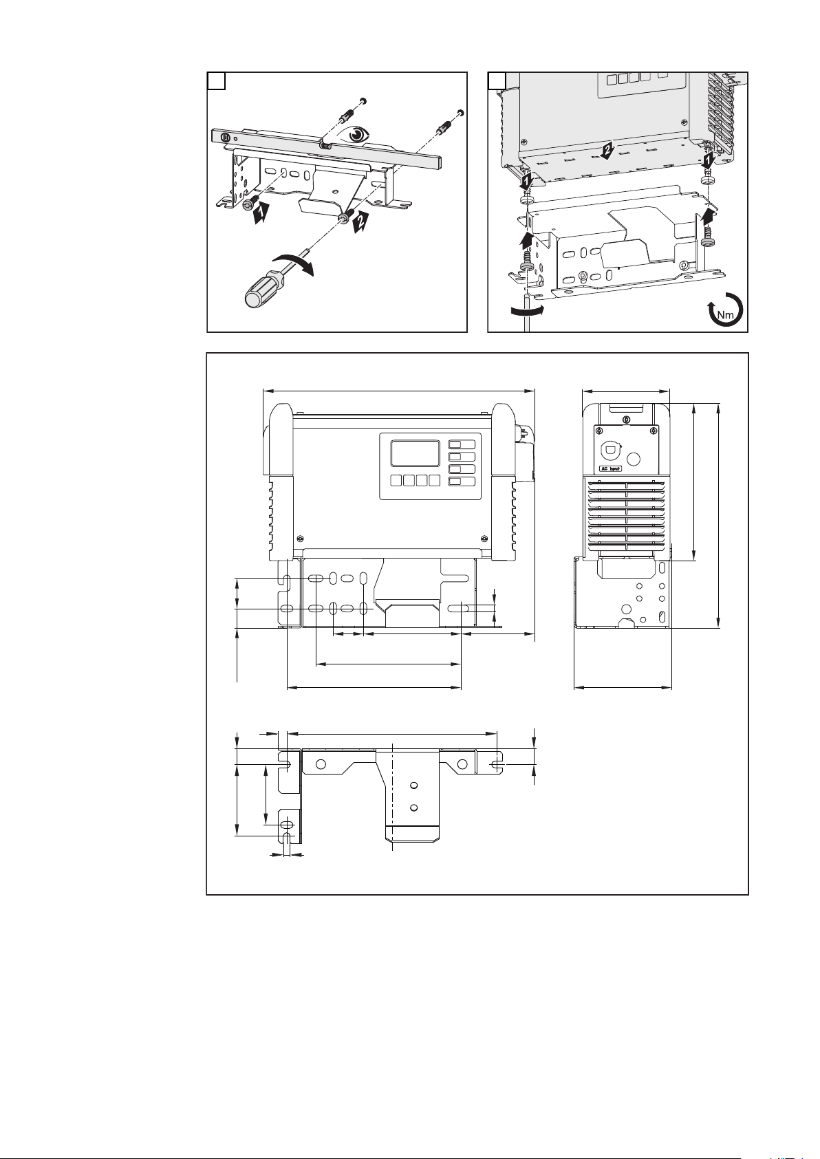
1
*
TX25
3
3
3
*
*
B1in. (mm)
13.43 (341)
7.17 (182)
1.5 (38) 4.86 (123,5) 3.6 (91,5)
.33 (8,5)
8.66 (220) 4.84 (123)
4.33 (110)
7.8 (198)
11.14 (283)
1.5 (38) .96 (24,5)
.43 (11)
.33 (8,5)
3.54 (90)
2.99 (76)
.79 (20)
.79 (20)
10.47 (266)
2
90
Page 91
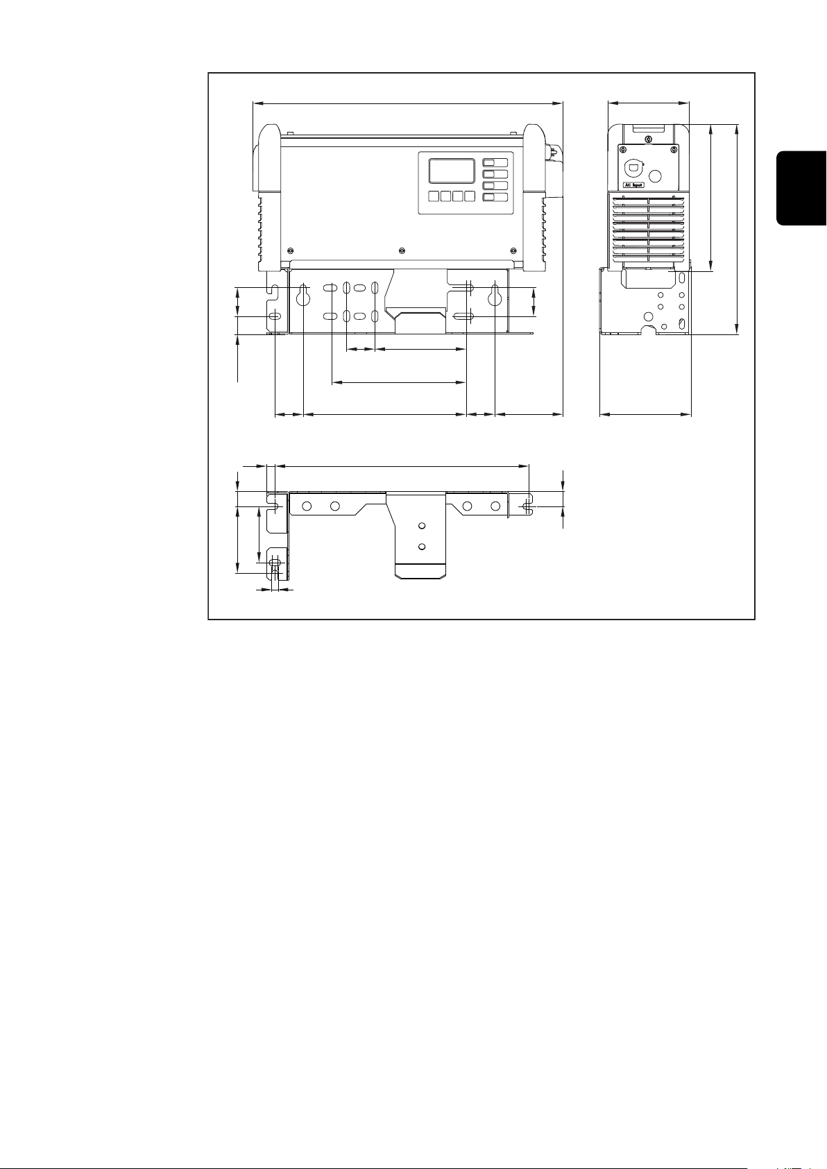
C1in. (mm)
16.42 (417)
7.17 (182)
1.5 (38) 4.86 (123,5)
1.57 (40) 3.52 (89,5)1.5 (38)
.43 (11)
.33 (8,5)
13.46 (342)
8.66 (220)
4.84 (123)
4.33 (110)
7.8 (198)
11.14 (283)
1.5 (38)
.79 (20) 3.54 (90)
1.5 (38)
.79 (20)
.96 (24,5)
2.99 (76)
ES
91
Page 92
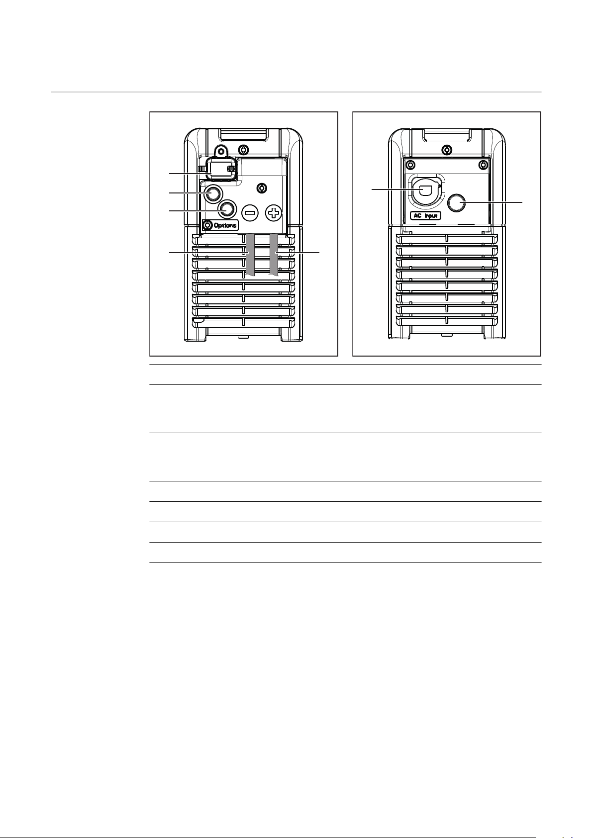
Elementos de manejo y conexiones
(3) (4)
(1)
(2)
(2)
(5)
(6)
Elementos de
manejo y bornas
de conexión
N.º Función
(1) Conexión USB
La conexión USB permite actualizar el equipo y protocolizar los parámetros de carga durante el proceso de carga mediante memoria USB.
(2) Posición para opciones
- Opción marcha/parada externa
- Opción carga con control de temperatura
(3) Borna de conexión para cable de carga (-)
(4) Borna de conexión para cable de carga (+)
(5) Cable de red
(6) Posición para la opción de circulación de electrolito
92
Page 93
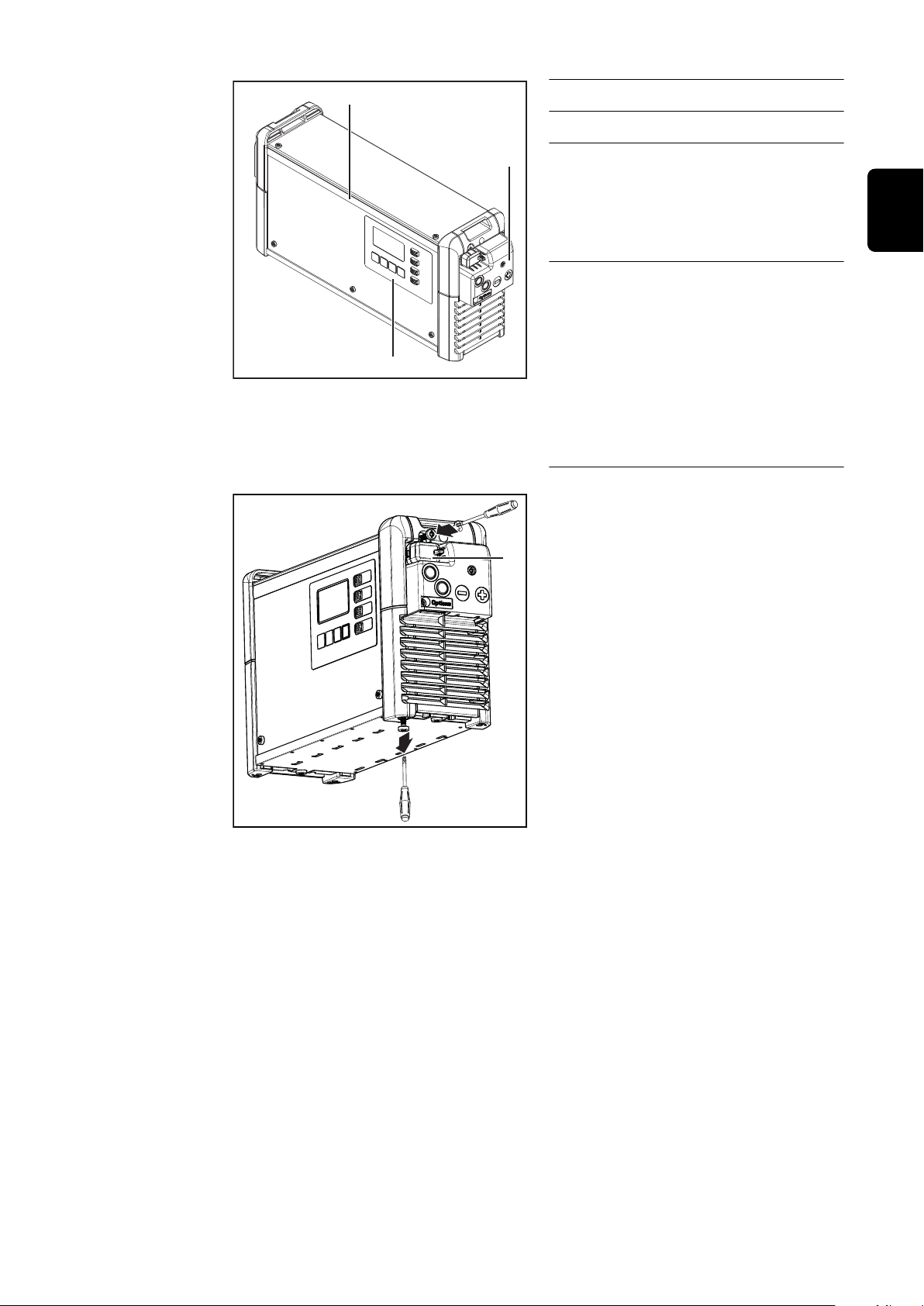
(7)
(8)
(9)
N.º Función
2
1
TX25
(1)
(7) Panel de control
(8) Banda de LED opcional
Se ilumina en diferentes colores
dependiendo del estado de
carga, según las indicaciones en
el apartado "Panel de control".
(9) Cubierta para conector opcion-
al y cables de carga
Para acceder al conector opcional y los cables de carga es
necesario retirar la cubierta (9).
Para ello, seguir las advertencias que figuran en el capítulo
"Opciones", apartado "Seguridad".
La cubierta (1) para la conexión USB se
puede asegurar mediante un tornillo.
ES
93
Page 94
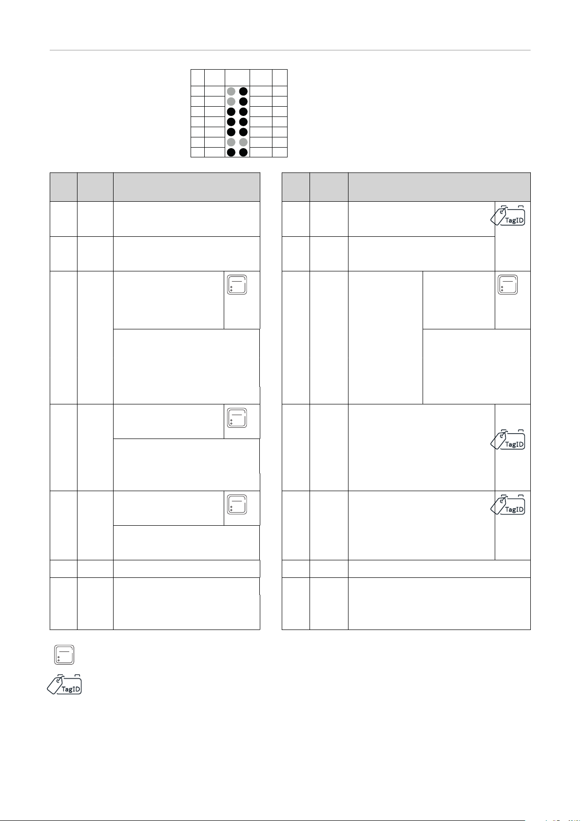
Asignación de
13 S 1 Dete
S 2 C2 G
C1 G
C1 L
13V O
C2 L
C1 H C2 H
- St + St
Pin Pin
Plug
Code
Plug
Code
Plug
14p
11
9
7
5
3
1
14
12
10
4
6
8
2
conexiones conector opcional 2
kW
Conector opcional 14 polos en el interior de la carcasa
Plug
Pin
Code Function
13 S 1
wire white
Pin
Plug
Code Function
14 Dete Detect
11 S 2 12 C2 G CAN 2GND
wire brown
9 C1 G CAN 1GND 10 13 VO13 V
wire brown Power Sup-
Remote Control wire 4 *
Option Box wire brown * Option Box wire
CBG Easy GND * CBG Easy VCC *
7 C1 L CAN 1Low 8 C2 L CAN 2Low
ply
wire white
Remote Control
wire 1 *
white *
wire yellow wire yellow
Remote Control wire 3 *
Option Box wire yellow *
CBG Easy Detect *
5 C1 H CAN 1High 6 C2 H CAN 2High
wire green wire green
Option Box wire green *
3 4
1 - St Temperature Controlled 2 + St Temperature Controlled
Charging * Charging *
Extern Start / Stop Extern Start / Stop
94
Remote Control wire 2 *
Gateway Link *
TagID Link *
* no disponible en Selectiva UL
Page 95
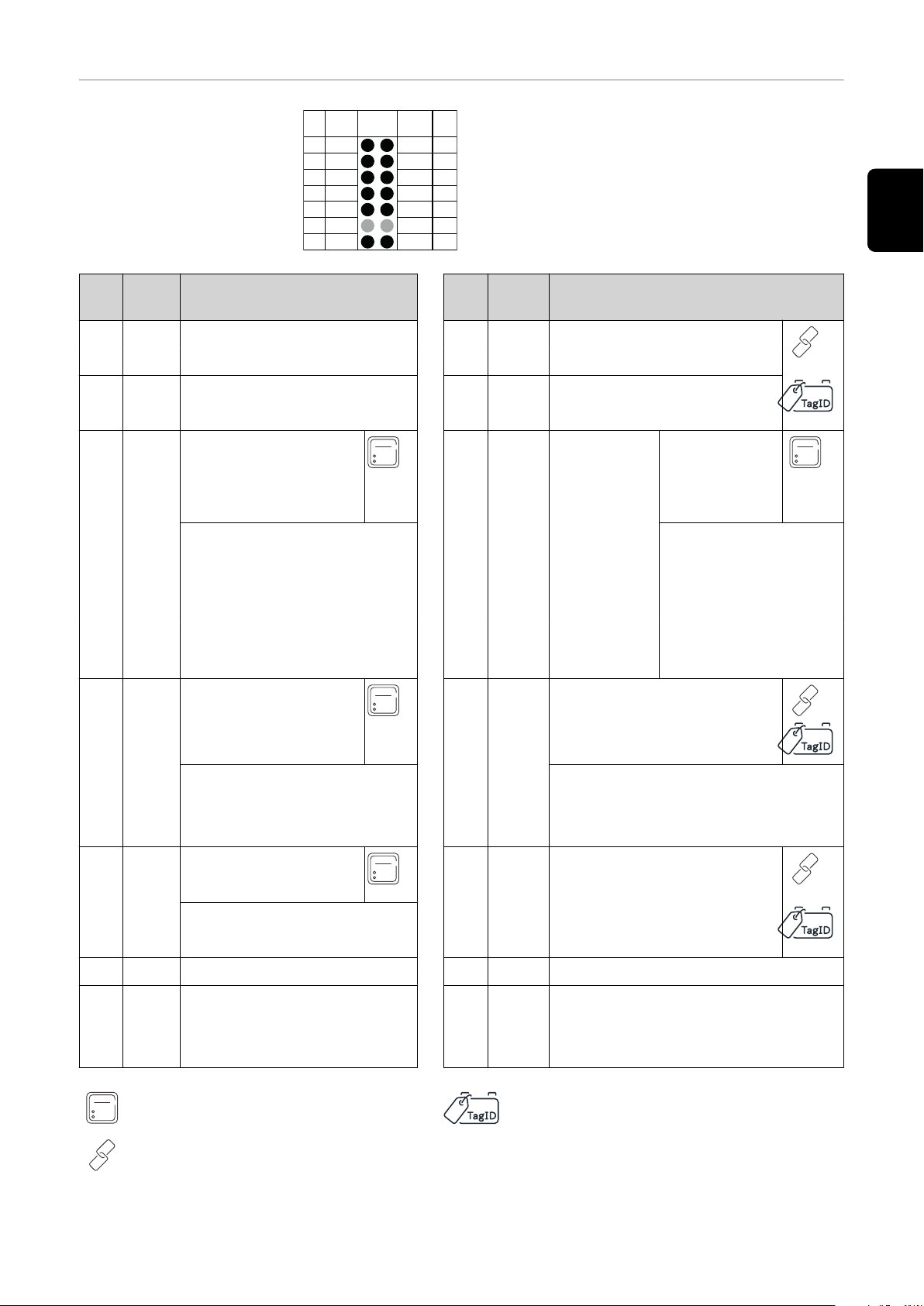
Asignación de
13 S 1 Dete
S 2 C2 G
C1 G
C1 L
13V O
C2 L
C1 H C2 H
- St + St
Pin Pin
Plug
Code
Plug
Code
Plug
14p
11
9
7
5
3
1
14
12
10
4
6
8
2
conexiones conector opcional 3
kW
Conector opcional 14 polos en el interior de la carcasa
ES
Plug
Pin
Code Function
13 S 1 Status 1
Pin
11 S 2 Status 2 12 C2 G CAN 2GND
Plug
Code Function
14 Dete Detect
wire white
wire brown
9 C1 G CAN 1GND 10 13 VO13 V
wire white
wire brown Power Sup-
Remote Control wire 4 *
Option Box wire brown * Opt. Box wire white *
CBG Easy GND CBG Easy VCC
ply
Remote Control wire
1 *
Status
Air Puls *
7 C1 L CAN 1Low 8 C2 L CAN 2Low
wire yellow wire yellow
Option Box wire yellow *
CBG Easy Detect
5 C1 H CAN 1High 6 C2 H CAN 2High
wire green wire green
Option Box wire green *
3 4
1 - St Temperature Controlled 2 + St Temperature Controlled
Charging * Charging *
Extern Start / Stop Extern Start / Stop
Remote Control wire 3 *
Air Puls *
Remote Control wire 2 *
Gateway Link *
TagID Link *
Battery Link * * no disponible en Selectiva UL
95
Page 96
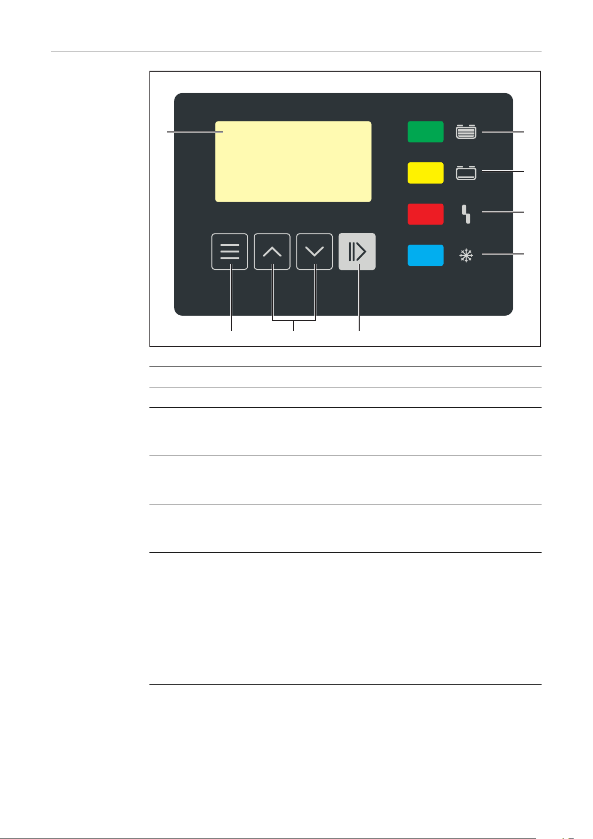
Panel de control
(1) (8)
(7)
(6)
(5)
(4)(3)(2)
N.º Función
(1) Pantalla
(2) Tecla "Menu" (Menú)
Selección del menú deseado.
Volver a la selección anterior.
(3) Teclas "Arriba/abajo"
Selección del punto de menú deseado.
Ajuste del valor deseado.
(4) Tecla "Pausa/inicio"
Interrumpir y reanudar el proceso de carga.
Confirmar un punto de menú o un ajuste.
(5) Indicación "Batería enfriada" (azul)
Significa que la batería está enfriada y lista para el uso.
Se ilumina de forma permanente: después del final de carga se ha alcanzado el tiempo de enfriamiento ajustado u opcionalmente la temperatura
de la batería.
Parpadea una vez por segundo: Adicionalmente se ha disparado la indicación de relleno de agua. En el capítulo "Indicación", apartado Funciones
adicionales en el modo de configuración, se incluye información más de-
tallada.
96
(6) Indicación "Error" (rojo)
Se ilumina de forma permanente: el equipo emite un error. La situación
actual no permite una carga correcta. No se puede realizar ninguna carga
mientras la indicación roja está iluminada (carga interrumpida). La pantalla indica el correspondiente mensaje de estado.
Page 97

Parpadea brevemente cada 3 segundos: el equipo emite una advertencia.
La carga continúa aunque los parámetros de carga no son favorables. La
pantalla muestra alternativamente el correspondiente mensaje de estado
y el estado de carga.
(7) Indicación "Carga" (amarillo)
Está iluminada: durante la carga.
Parpadea: cuando se ha interrumpido la carga.
(8) Indicación "La batería está cargada" (verde)
Se ilumina de forma permanente: la carga ha finalizado.
Parpadea una vez por segundo: la carga ha finalizado. Adicionalmente se
ha disparado la indicación de relleno de agua. En el capítulo "Indicación",
apartado Funciones adicionales en el modo de configuración, se incluye
información más detallada.
ES
97
Page 98
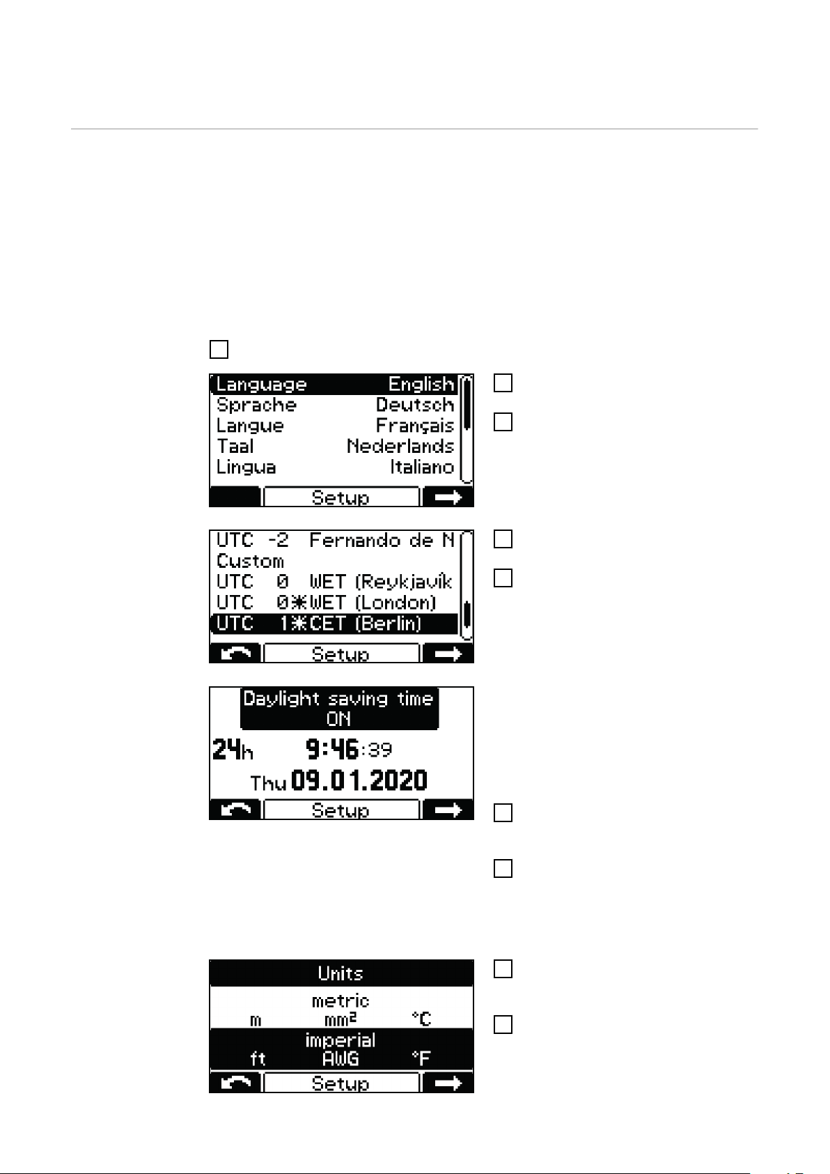
Cargar la batería
Primera puesta
en marcha
Si el cargador se conecta por primera vez a la red eléctrica, este se encuentra en
el modo de configuración.
En este modo se deben realizar o confirmar los siguientes ajustes básicos:
Idioma (inglés, alemán, francés, etc.)
-
Fecha, hora y zona horaria
-
Unidades: métricas / imperiales
-
Longitud y sección del cable de carga
-
Tipo de batería, curva característica, número de celdas y tiempo de carga o
-
capacidad de batería
Conectar la clavija para la red del cargador a la red eléctrica.
1
Seleccionar el idioma deseado del
2
menú con las teclas "Arriba/abajo".
Confirmar con la tecla "Pausa/
3
inicio".
El idioma inglés está establecido como
predeterminado.
Seleccionar la zona horaria con las
4
teclas "Arriba/abajo".
Confirmar con la tecla "Pausa/
5
inicio".
La zona horaria UTC+1 Central
European Time (Berlín) está establecida como predeterminada.
Deben efectuarse los siguientes
ajustes:
Horario de verano ON/OFF
-
Formato de horas
-
Hora
-
Fecha
-
Seleccionar el ajuste deseado en
6
cada momento con las teclas "Arriba/abajo".
Confirmar el ajuste con la tecla
7
"Pausa/inicio".
El ajuste por defecto es: horario de
verano activado y formato de 24 horas.
Seleccionar el ajuste deseado en
8
cada momento con las teclas "Arriba/abajo" (métricas / imperiales).
Confirmar con la tecla "Pausa/
9
inicio".
98
Page 99
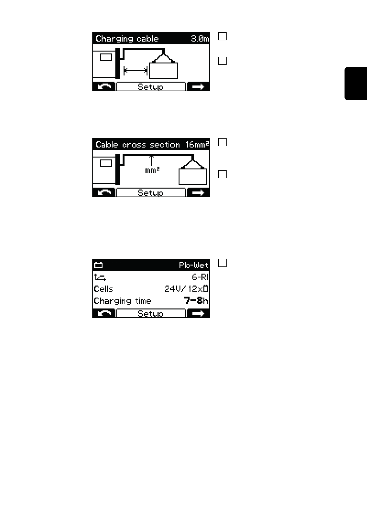
Ajustar la longitud del cable de
10
carga correspondiente con las teclas "Arriba/abajo" (m / ft).
Confirmar con la tecla "Pausa/
11
inicio".
El cargador de batería está configurado con la longitud correspondiente
al pedido.
Un ajuste incorrecto de la longitud del
cable de carga puede influir negativamente en el proceso de carga.
Ajustar la sección transversal del
12
cable de carga correspondiente
con las teclas "Arriba/abajo" (mm² /
AWG).
Confirmar con la tecla "Pausa/
13
inicio".
El cargador de batería está configurado con la sección transversal correspondiente al pedido.
Un ajuste incorrecto de la sección
transversal del cable de carga puede
influir negativamente en el proceso de
carga.
ES
Si la configuración de carga que se
14
muestra es correcta, confirmar con
la tecla "Pausa/inicio".
El cargador de batería está preconfigurado con los datos del pedido.
Si el cargador se ha encargado sin configuración adicional, los ajustes predeterminados son los siguientes:
Tipo de batería húmeda Pb (para PzS, GiS)
-
Curva característica 6 - RI
-
Máximo número de celdas previsto para el cargador de batería
-
Tiempo de carga 7-8 h
-
Si la configuración de la batería utilizada no es correcta, deben ajustarse los
parámetros como corresponda.
Hay información detallada sobre los parámetros de los cargadores en el capítulo
"Indicación", apartado Modo de configuración
99
Page 100
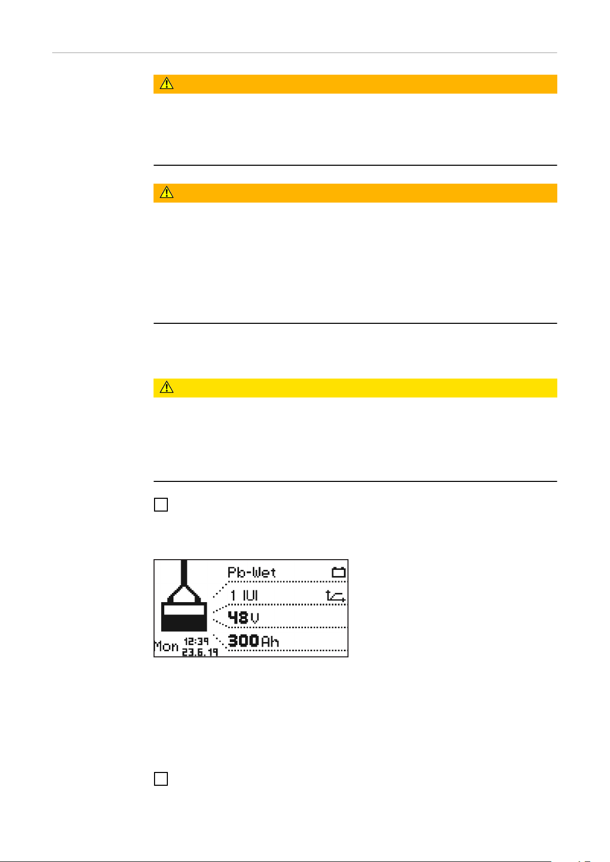
Iniciar el proceso de carga
¡PELIGRO!
Peligro por la salida de ácido de la batería o la explosión durante la carga de
baterías defectuosas.
La consecuencia pueden ser graves daños personales y materiales.
Antes de comenzar el proceso de carga, asegurarse de que la batería no
▶
presenta daños.
¡PELIGRO!
Riesgos por la inexactitud del tipo de batería y los ajustes de carga.
La consecuencia pueden ser graves daños personales y materiales.
Antes de comenzar el proceso de carga, asegurar que esté ajustado el tipo
▶
de batería correcto en el cargador.
Deben establecerse los siguientes ajustes para cada tipo de batería antes de
▶
la carga:
Curva de carga
Tensión nominal (número de celdas de la batería)
Capacidad de la batería (Ah) o tiempo de carga (h)
Hay información detallada sobre los parámetros de los cargadores en el capítulo
"Indicación", apartado Modo de configuración.
¡PRECAUCIÓN!
Peligro de daños materiales debido a suciedad intensa en los contactos del enchufe de carga.
Debido al consiguiente aumento de la resistencia de transición puede producirse
un calentamiento excesivo y posteriormente la destrucción del enchufe de carga.
Mantener los contactos del enchufe de carga libres de impurezas, y limpiar-
▶
los si fuera necesario.
Conectar la clavija para la red del cargador a la red eléctrica.
1
Se preguntará si están ajustados los parámetros correctos para la batería que va
a cargarse.
A continuación, aparece la indicación
en el modo estándar. La pantalla indica
los parámetros del cargador:
Tipo de batería (por ejemplo, Pb-
-
WET)
Curva característica de carga (por
-
ejemplo, IUI)
Tensión nominal (por ejemplo, 48
-
V)
Capacidad (por ejemplo, 300 Ah)
-
Día de la semana, hora y fecha
-
100
Los parámetros del cargador se pueden personalizar. Hay información detallada
sobre los parámetros de los cargadores en el capítulo "Indicación", apartado
Modo de configuración. Asegurarse de que la batería se corresponde con la con-
figuración del cargador.
Enchufar el enchufe de carga.
2
 Loading...