

Page 1

Operating
Instructions
Selectiva 3.0
2-3 kW
Operating Instructions
EN
42,0426,0361,EN 012-12042023
Page 2

Page 3

Contents
Power categories 5
General 5
2 kW 5
3 kW 5
Safety rules 6
General 6
Environmental conditions 6
Mains connection 6
Dangers due to grid and charging current 7
Danger due to acid, gases and vapours 7
General information on working with batteries 7
Personal protection and protection of others 8
Safety measures in normal operation 8
EMC device classifications 8
EMC measures 8
Data protection 8
Maintenance 9
Maintenance and repair 9
Obligations of the operating company 9
Safety inspection 9
Markings on the device 9
Disposal 9
Copyright 10
General information 11
Explanation of safety notices 11
Device concept 11
Proper use 11
Grid connection 12
Charging lead 13
Correct installation of the mains/charging cables 13
Warning notices on the device 14
Warning notices inside the device 15
Setup regulations 15
Wall and floor bracket 17
Control elements and connections 20
Operating controls and connections 20
Pin assignment of the 2 kW option plug 21
Pin assignment of the 3 kW option plug 22
Control panel 24
Charging the battery 26
Starting for the first time 26
Starting the charging process 27
Interrupting the charging process 29
Stopping charging 30
Display 32
Overview of display modes 32
Standard mode 32
Menu selection 33
Statistics mode 33
History mode 33
Configuration mode 35
Overview of charging settings 38
Electrolyte circulation 39
Temperature-controlled charging 39
Equalising charge 40
Delay 41
Calendar 42
Special charges 44
“Opportunity Charge” special function 44
DC connection 45
EN
3
Page 4

Additional functions 45
General settings 47
Reset settings 49
USB mode 49
Status codes 51
Options 56
Safety 56
Electrolyte circulation 3 kW 56
External start/stop 58
Temperature-controlled charging 58
LED strip 58
Air filter 59
Wall and floor bracket 59
"Mobile" kit 59
Option box 59
Remote control system 59
Mounting plate 59
TagID 60
TagID Link 60
Technical data 61
Selectiva 2 kW 61
Selectiva 3 kW 62
4
Page 5

Power categories
General The kW information for the power categories relates to the housing design and is
not directly related to the actual device output.
2 kW Selectiva
2040/2050/2060/2070
4020/4035
3 kW Selectiva
2080/2100/2120
4045/4060
EN
5
Page 6

Safety rules
General The device has been manufactured in line with the state of the art and according
to recognized safety standards. If used incorrectly or misused, however, it can
cause:
Serious or fatal injury to the operator or third parties
-
Damage to the device and other material assets belonging to the operating
-
company
Inefficient operation of the device
-
All persons involved in the commissioning, operation, maintenance, and servicing
of the device must:
Be suitably qualified
-
Have fully read and precisely followed these Operating Instructions
-
The Operating Instructions must always be kept to hand wherever the device is
being used. In addition to the Operating Instructions, all applicable local rules
and regulations regarding accident prevention and environmental protection
must also be followed.
All safety and danger notices on the device:
Must be kept in a legible state
-
Must not be damaged
-
Must not be removed
-
Must not be covered, pasted, or painted over
-
Environmental
conditions
Mains connection
For the location of the safety and danger notices on the device, refer to the section headed "General information" in the Operating Instructions for the device.
Before switching on the device, eliminate any faults that could compromise
safety.
Your personal safety is at stake!
Operation or storage of the device outside the stipulated area will be deemed as
not in accordance with the intended purpose. The manufacturer shall not be held
liable for any damage arising from such usage.
For exact information on permitted environmental conditions, please refer to the
"Technical data" section.
Devices with a higher rating may affect the energy quality of the mains due to
their current consumption.
This may affect device types in terms of:
Connection restrictions, requirements regarding permitted mains impedance
-
*)
-
Requirements with regard to the minimum short-circuit power requirement
*)
*)
at the interface with the public grid
see "Technical data"
In this case, the operating company or the person using the device should check
whether the device may be connected, possibly by discussing the matter with the
energy company where appropriate.
6
Page 7

IMPORTANT! Ensure that the grid connection is earthed properly!
EN
Dangers due to
grid and charging current
Danger due to
acid, gases and
vapours
Working with battery chargers poses a number of dangers, such as:
Electrical hazard due to grid and charging current
-
Hazardous electromagnetic fields that may pose a risk of death for individu-
-
als with pacemakers.
An electric shock can be fatal. Every electric shock poses a risk of death. To prevent electric shock during operation:
Do not touch any voltage-carrying parts inside or outside of the device.
-
Never touch the battery poles.
-
Do not short-circuit the charging cable or charging terminals.
-
All cables and leads must be secured, undamaged, insulated, and adequately dimensioned. Loose connections, scorched, damaged, or under-dimensioned
cables and leads must be repaired immediately by an authorized specialist.
Batteries contain acids which pose a risk to the eyes and skin. Furthermore, charging batteries produces gases and vapors that may be hazardous to your health
and are highly explosive under certain circumstances.
Only use battery chargers in well ventilated rooms in order to prevent the accumulation of explosive gases. Battery charging rooms are not considered at risk of
explosion if a hydrogen concentration of less than 4 % is guaranteed by natural or
artificial ventilation.
General information on working
with batteries
During charging, observe a minimum distance of 0.5 m (19.69 in.) between the
battery and battery charger. Keep potential sources of ignition such as fire and
open flames away from the battery.
Never disconnect the battery (e.g., charging terminals) during charging.
Never breathe in the gases and vapors produced by the battery – ensure there is
a sufficient supply of fresh air.
Do not place any tools or electrically conductive metals on the battery, in order
to prevent short circuits.
Never allow battery acid to come into contact with your eyes, skin, or clothing.
Wear eye protection and appropriate protective clothing. Rinse away any
splashed acid immediately and thoroughly with clean water, and consult a physician if necessary.
Protect batteries from dirt and mechanical damage.
-
Store charged batteries in cool rooms. The lowest self discharge occurs at
-
approx. +2°C (35.6°F).
Refer to the specifications of the battery manufacturer or conduct weekly
-
visual inspections to ensure that the battery is filled with acid (electrolyte)
up to the maximum marking.
Do not start operating the device, or immediately stop operation, and have
-
the battery inspected by an authorized specialist if:
The acid level is uneven or there is high water consumption in individual
-
cells caused by a possible defect
The battery heats up to an impermissible level, above 55°C (131°F)
-
7
Page 8

Personal protection and protection of others
Keep persons, especially children, away from the device and working area during
operation. However, if persons are in the vicinity:
Inform them of any dangers (hazardous acids and gases, risk due to grid and
-
charging current, etc.),
Provide suitable protective equipment.
-
Before leaving the working area, ensure that no personal injury or property damage can occur in your absence.
Safety measures
in normal operation
EMC device classifications
Operate devices with ground conductors only on a grid with a ground conductor
and a socket with a ground conductor contact. Operating the device on a grid
without a ground conductor or on a socket without a ground conductor contact is
considered gross negligence. The manufacturer accepts no liability for any damage resulting from improper use.
Only operate the device in accordance with the protection class shown on the
rating plate.
Never commission the device if it is damaged.
Have the grid and device supply lead regularly inspected by an electrician to ensure that the ground conductor is functioning properly.
Safety devices that are not fully functional and components with defects must
be repaired by an authorized specialist before the device is turned on.
Never bypass or disable protection devices.
A freely accessible mains plug is required after installation.
Devices with emission class A:
Are only designed for use in an industrial setting.
-
Can cause conducted and emitted interference in other areas.
-
Devices with emission class B:
Satisfy the emissions criteria for residential and industrial areas. This also
-
applies to residential areas in which power is supplied from the public lowvoltage grid.
EMC device classification according to the rating plate or the technical data.
EMC measures In certain cases, even though a device complies with the standard limit values for
emissions, it may affect the application area for which it was designed (e.g. when
there is sensitive equipment at the same location, or if the site where the device
is installed is close to either radio or television receivers).
If this is the case, then the operating company is obliged to take appropriate action to rectify the situation.
Data protection The user is responsible for the safekeeping of any changes made to the factory
settings. The manufacturer accepts no liability for any deleted personal settings.
8
Page 9

Maintenance Before each start-up, check the mains plug and mains cable and charging cables
and charging terminals for damage.
If dirt accumulates on the device, clean the surface of the device housing with a
soft cloth and only with solvent-free cleaning agents.
EN
Maintenance and
repair
Obligations of
the operating
company
Safety inspection
Maintenance and repair work must only be carried out by authorised personnel.
Use only original spare and wearing parts (also applies to standard parts). It is
impossible to guarantee that bought-in parts are designed and manufactured to
meet the demands made on them, or that they satisfy safety requirements.
Modifications, installations or conversions are only permitted with the approval
of the manufacturer.
The operating company must only allow persons to work with the device who:
Are familiar with the fundamental instructions regarding safety at work and
-
accident prevention and have been instructed in how to use the device
Have read and understood these Operating Instructions, especially the
-
"Safety rules" section and have confirmed as much with their signatures
Are trained to produce the required results.
-
Checks must be carried out at regular intervals to ensure that operators are
working in a safety-conscious manner.
The manufacturer recommends that a safety inspection of the device is performed at least once every 12 months.
The safety inspection may only be performed by an appropriately qualified electrician
After any changes have been made
-
After any additional parts are installed, or after any conversions
-
After repair, care and maintenance are carried out
-
At least every twelve months
-
For safety inspections, follow the appropriate national and international standards and directives.
Further details on safety inspections can be obtained from your service centre.
They will provide you on request with any documents you may require.
Markings on the
device
Disposal Waste electrical and electronic equipment must be collected separately and re-
Devices with the CE marking satisfy the essential requirements of the applicable
guidelines.
Devices displaying the EAC mark of conformity satisfy the requirements of the
relevant standards in Russia, Belarus, Kazakhstan, Armenia and Kyrgyzstan.
cycled in an environmentally responsible manner in accordance with the EU Directive and national law. Used equipment must be returned to the distributor or
through a local, authorised collection and disposal system. Proper disposal of the
old device promotes sustainable recycling of material resources. Ignoring this
may lead to potential health/environmental impacts.
9
Page 10

Packaging materials
Collected separately. Check your municipality’s regulations. Reduce the volume
of the box.
Copyright Copyright of these Operating Instructions remains with the manufacturer.
Text and illustrations were accurate at the time of printing. Fronius reserves the
right to make changes. The contents of the Operating Instructions shall not
provide the basis for any claims whatsoever on the part of the purchaser. If you
have any suggestions for improvement, or can point out any mistakes that you
have found in the Operating Instructions, we will be most grateful for your comments.
10
Page 11

General information
EN
Explanation of
safety notices
DANGER!
Indicates immediate danger.
If not avoided, death or serious injury will result.
▶
WARNING!
Indicates a potentially hazardous situation.
If not avoided, death or serious injury may result.
▶
CAUTION!
Indicates a situation where damage or injury could occur.
If not avoided, minor injury and/or damage to property may result.
▶
NOTE!
Indicates a risk of flawed results and possible damage to the equipment.
Device concept The single-phase battery charging systems for 24 V and 48 V batteries are fitted
with intelligent charging technology. The successful Active Inverter Technology
with the revolutionary Ri charging process adapts itself to the requirements of
the battery and only charges the battery with the current that it actually needs.
The technology is embedded in a robust industry-standard housing. The exceptionally compact design complies with all safety standards, requires less installation space and protects the components to ensure a long service life.
Fitted with a graphical display, an integrated datalogger, new interfaces and additional options, the device is perfectly equipped for the future.
Proper use The battery charger is intended to charge the following listed batteries. Any oth-
er use is deemed to be "not in accordance with the intended purpose." The manufacturer shall not be liable for any damage resulting from such improper use. Intended use also means:
Following all the instructions in these Operating Instructions
-
Regularly checking the mains cable and charging cable
-
WARNING!
Danger from charging dry batteries (primary cells) and non-rechargeable batteries.
Serious personal injury and property damage due to leaking batteries may result.
Only charge the types of battery listed below.
▶
11
Page 12

WARNING!
Danger from charging unsuitable batteries.
Serious personal injury and property damage as a result of escaping gases, ignition, or explosion may result.
Only connect batteries to the battery charger which are suitable for the bat-
▶
tery charger in terms of their type, voltage, and capacity and which correspond to the settings on the battery charger.
The battery charger is designed for charging lead acid batteries and NiCd batteries.
Pb-WET batteries (PzS, GiS, ...):
-
Venting, closed lead acid wet batteries with liquid electrolyte.
Pb-GEL batteries (PzV, GiV, ...):
-
Valve-regulated, sealed lead acid batteries (VRLA) with fixed electrolyte (gel
or fleece).
NiCd batteries:
-
Closed or sealed NiCd batteries with liquid electrolyte.
Pb-CSM-WET batteries (Copper Strained Metal):
-
Closed lead acid CSM batteries with liquid electrolyte.
Lead Crystal batteries:
-
Type EVFJ/CNFJ Lead Crystal batteries.
The device must be handled correctly in order for it to work. Never pull on the
cable when handling the device.
Grid connection
WARNING!
Danger from electric current.
This can result in serious injury or death.
Before starting work, switch off all the devices and components involved and
▶
disconnect them from the grid.
Secure all the devices and components involved to prevent unintentional re-
▶
starting.
WARNING!
Danger due to incorrect operation and incorrectly performed work.
This can result in serious injury and damage to property.
All the work and functions described in this document must only be carried
▶
out by trained and qualified personnel.
Read and understand this document.
▶
Read and understand all the Operating Instructions for the system compon-
▶
ents, especially the safety rules.
WARNING!
Danger due to faulty or insufficient power supply.
This can result in serious injury and damage to property.
The power supply requirements detailed in "Technical data" must be met.
▶
12
Page 13

Charging lead
WARNING!
Danger from flying sparks due to improper disconnection of the charging plug.
This can result in severe personal injury and damage to property. The resulting
sparks can ignite the charging gases that form during charging and cause a fire or
explosion
End the charging process via the battery charger and, after the charging
▶
cables have cooled down, wind them up or, if available, place them on the
cable holder.
EN
Correct installation of the
mains/charging
cables
WARNING!
Danger due to charging cables lying around.
This can result in severe personal injury and damage to property. Personnel can
get caught or trip on unplugged, loose cables.
Lay charging cables so that no one can trip over them or get caught on them.
▶
CAUTION!
Danger due to overheating as a result of incorrectly laid mains/charging cables.
Risk of damage to the mains/charging cables.
The mains/charging cable may only be replaced by a qualified electrician.
▶
Lay the mains/charging cable without a loop.
▶
Do not cover the mains/charging cable.
▶
Charging cables longer than 5 m (16 ft. 4.85 in.) must be laid individually (no
▶
bundling).
Charging cables longer than 5 m (16 ft. 4.85 in.) can have an increased sur-
▶
face temperature (be aware of hot surfaces).
In the following cases, pay special attention that the surface temperature of
▶
the charging cables does not exceed 80°C (176°F):
- Ambient temperature is 30°C (86°F) or more
- Cross-section of the charging cable is 95 mm2 or more
- Length of the charging cable is 5 m (16 ft. 4.85 in.) or more
13
Page 14

Warning notices
Selectiva x.0 xxxx xkW
4,010,xxx
xxxxxxxx
XXXX
xxxxxxxx
OVC II
U
AC nom.
I
AC max.
P
AC max.
UDC nom.
IDC max.
Part No.:
Ser. No.:
Fronius International GmbH
Froniusstraße 1
4643 Pettenbach
Austria
Protective class I
IP21
1~ NPE 230V 50/60Hz
xxA
xxV
xxxxW
xxA
www.fronius.com
Ladevorgang immer stoppen bevor das Ladekabel abgezogen wird!
Explosive Gase. Flammen und Funken vermeiden.
Während des Ladens für ausreichend Frischluft-Zufuhr sorgen!
Always stop charging before you disconnect the charging cable!
Explosive gases. Prevent flames and sparks.
Provide adequate ventilation during charge!
T
oujours arrêter la charge avant de déconnecter le câble de charge!
Gaz explosifs. Éviter les flammes et les étincelles.
Prévoir une ventilation adaptée pendant la charge!
¡Detener siempre la carga antes de desconectar el cable de carga!
Gases explosivos. Evitar llamas y chipas.
¡Mantener una ventilación adecuada durante la carga!
Interrompere sempre la carica prima di scollegare il cavo di carica!
Gas esplosivi. Evitare fiamme libere e scintille.
Predisporre una ventilazione adeguata durante la carica!
W
ARNUNG -
W
ARNING -
ATTENTION
ADVERTENCI
A
- A
VVISO
42,0409,0419
on the device
A number of safety symbols can be seen on the battery charger. The safety symbols must not be removed or painted over.
Do not dispose of used devices with domestic waste. Dispose of them
according to the safety rules.
Possible sources of ignition, such as fire, sparks and naked flames,
must be kept away from the battery.
Risk of explosion! Oxyhydrogen is generated in the battery during charging.
Battery acid is corrosive and must be kept away from eyes, skin and
clothes.
Ensure an adequate supply of fresh air during charging.
Do not use the functions until you have fully read the Operating Instructions.
14
Page 15

Warning notices
2 kW
4,010,xxx
xxxxxxxx
XXXX
UDC nom. xxV
Part No.:
Ser. No.:
1
2
1 Display
2 Battery CR2032
WARNING Hazardous Voltage
Kondensator Entladezeit < 2 min.
Capacitor discharge time < 2 min.
Décharge de condensateur < 2 min.
Condensador tiempo de descarga < 2 min.
Condensatore tempo di scaricamento < 2 min.
3 kW
4,010,xxx
xxxxxxxx
XXXX
UDC nom. xxV
Part No.:
Ser. No.:
1
2
1 Display
2 Battery CR2032
WARNING Hazardous Voltage
Kondensator Entladezeit < 2 min.
Capacitor discharge time < 2 min.
Décharge de condensateur < 2 min.
Condensador tiempo de descarga < 2 min.
Condensatore tempo di scaricamento < 2 min.
inside the device
WARNING!
Danger from electric shocks.
This can result in serious injury or death.
The housing must never be opened by anyone other than a service technician
▶
trained by the manufacturer.
The device must be disconnected from the mains before starting any work
▶
with the housing open. A suitable measuring instrument must be used to ensure that electrically charged components (e.g. capacitors) are fully discharged.
Use an easily legible and understandable warning sign to ensure that the
▶
device is not reconnected to the mains supply before all the work has been
completed.
Inside the device:
EN
Setup regulations
WARNING!
Danger from devices falling or toppling over.
This can result in severe personal injury and damage to property.
Set up all system components in a stable position.
▶
When using a floor bracket or wall bracket, always ensure that all fastening
▶
elements are firmly seated.
The device has been tested according to protection class 21. This means:
Protection against the penetration of solid foreign bodies with a diameter of
-
more than 12.5 mm (0.49 in.)
Protection against dripping water falling vertically
-
15
Page 16

The device can be set up and operated in dry, closed rooms in accordance with
(a)
protection class 21. Avoid exposure to moisture.
The permissible operating position of
the device is horizontal.
Cooling air
The device must be set up so that cooling air can flow through the housing openings provided unhindered. There must always be a minimum distance of 20 cm
(7.87 in.) from the air inlet and outlet openings. The ambient air must be free
from:
Excessive dust exposure
-
Electrically conductive particles (carbon black or metal chips)
-
Heat sources
-
Battery acid vapors
-
The cooling air flows in and out as indicated by the arrow symbols in the following illustrations.
CAUTION!
Danger due to partially or completely covered air intake and outlet openings.
This can result in damage to property.
The setup of several devices one behind the other should be staggered.
▶
16
If the devices are arranged in a line one behind the other without being
staggered, the distance between the devices must be as follows:
Minimum distance 20 cm (7.87 in.)
a)
Page 17

Wall and floor
*
TX25
3
3
3
*
*
bracket
WARNING!
Danger from incorrectly performed work and falling equipment.
This can result in severe personal injury and damage to property.
The mounting must only be carried out by trained and qualified personnel.
▶
Depending on the substrate, different dowels and screws are required. Therefore,
dowels and screws are not part of the scope of supply. The system installer is responsible for selecting the proper dowels and screws.
WARNING!
Danger from objects falling or toppling over.
This can result in severe personal injury and damage to property.
Only use this wall bracket with the battery charger provided by the manufac-
▶
turer.
Mount the device horizontally.
▶
For wall mounting, the load bearing capacity of the wall must be sufficient.
▶
Weight of wall bracket:
2 kW (B1) 1.10 kg (2.43 lb)
EN
3 kW (C1) 1.35 kg (2.98 lb)
1
2
17
Page 18

2 kW (B1)mm (in.)
341 (13.43)
182 (7.17)
38 (1.5) 123,5 (4.86) 91,5 (3.6)
8.5 (.33)
220 (8.66) 123 (4.84)
110 (4.33)
198 (7.8)
283 (11.14)
38 (1.5) 24,5 (.96)
11 (.43)
8.5 (.33)
90 (3.54)
76 (2.99)
20 (.79)
20 (.79)
266 (10.47)
18
Page 19

3 kW (C1)mm (in.)
417 (16.42)
182 (7.17)
38 (1.5) 123,5 (4.86)
40 (1.57) 89,5 (3.52)38 (1.5)
11 (.43)
8,5 (.33)
342 (13.46)
220 (8.66)
123 (4.84)
110 (4.33)
198 (7.8)
283 (11.14)
38 (1.5)
20 (.79) 90 (3.54)
38 (1.5)
20 (.79)
24,5 (.96)
76 (2.99)
EN
19
Page 20

Control elements and connections
(3) (4)
(1)
(2)
(2)
(5)
(6)
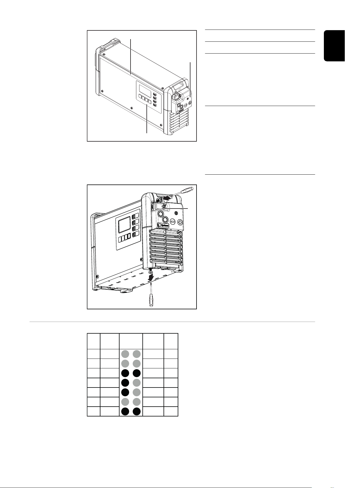
Operating controls and connections
No. Function
(1) USB port
The USB port allows a USB flash drive to be used to update the device
and also to log the charging parameters while charging is in progress.
(2) Position for options
- External start/stop option
- Temperature-controlled charging option
(3) Connection for (-) charging cable
(4) Connection for (+) charging cable
(5) Mains cable
(6) Position for electrolyte circulation option
20
Page 21
(7)
(8)
(9)
No. Function
2
1
TX25
(1)
13 S 1 Dete
S 2 C2 G
C1 G
C1 L
13V O
C2 L
C1 H C2 H
- St + St
Pin Pin
Plug
Code
Plug
Code
Plug
14p
11
9
7
5
3
1
14
12
10
4
6
8
2
(7) Control panel
(8) LED strip option
Lights up in the appropriate colors depending on the state of
charge, according to the indicators explained in the "Control
panel" section
(9) Cover for option plug and char-
ging cables
The option plug and the charging cables are only accessible
by removing the cover (9). To do
this, follow the warnings in the
"Safety" section of the "Options" chapter.
The cover (1) for the USB port can be
secured with a screw.
EN
Pin assignment
of the 2 kW option plug
14-pin option plug inside the housing
21
Page 22
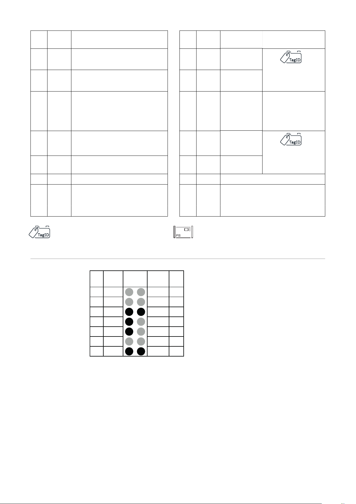
Plug
13 S 1 Dete
S 2 C2 G
C1 G
C1 L
13V O
C2 L
C1 H C2 H
- St + St
Pin Pin
Plug
Code
Plug
Code
Plug
14p
11
9
7
5
3
1
14
12
10
4
6
8
2
Pin
Code Function
Plug
Pin
Code
Function
13 S 1
wire white
11 S 2 12 C2 G
wire brown
9 C1 G Remote Control wire 4
Option Box wire brown
CBG Easy GND
14 Dete
10 13 VO13 V
Detect
CAN 2 GND
Power
Supply
Remote Control
wire 1
Option Box
wire white
7 C1 L Remote Control wire 3
Option Box wire yellow
CBG Easy Detect
5 C1 H Remote Control wire 2
Option Box wire green
3 4
8 C2 L
6 C2 H
CAN 2 Low
wire yellow
CAN 2 High
wire green
CBG Easy VCC
1 - St Temperature Controlled 2 + St Temperature Controlled
Charging Charging
Extern Start / Stop Extern Start / Stop
TagID Link
Pin assignment
of the 3 kW option plug
Optional for Pb Chargers
14-pin option plug inside the housing
22
Page 23
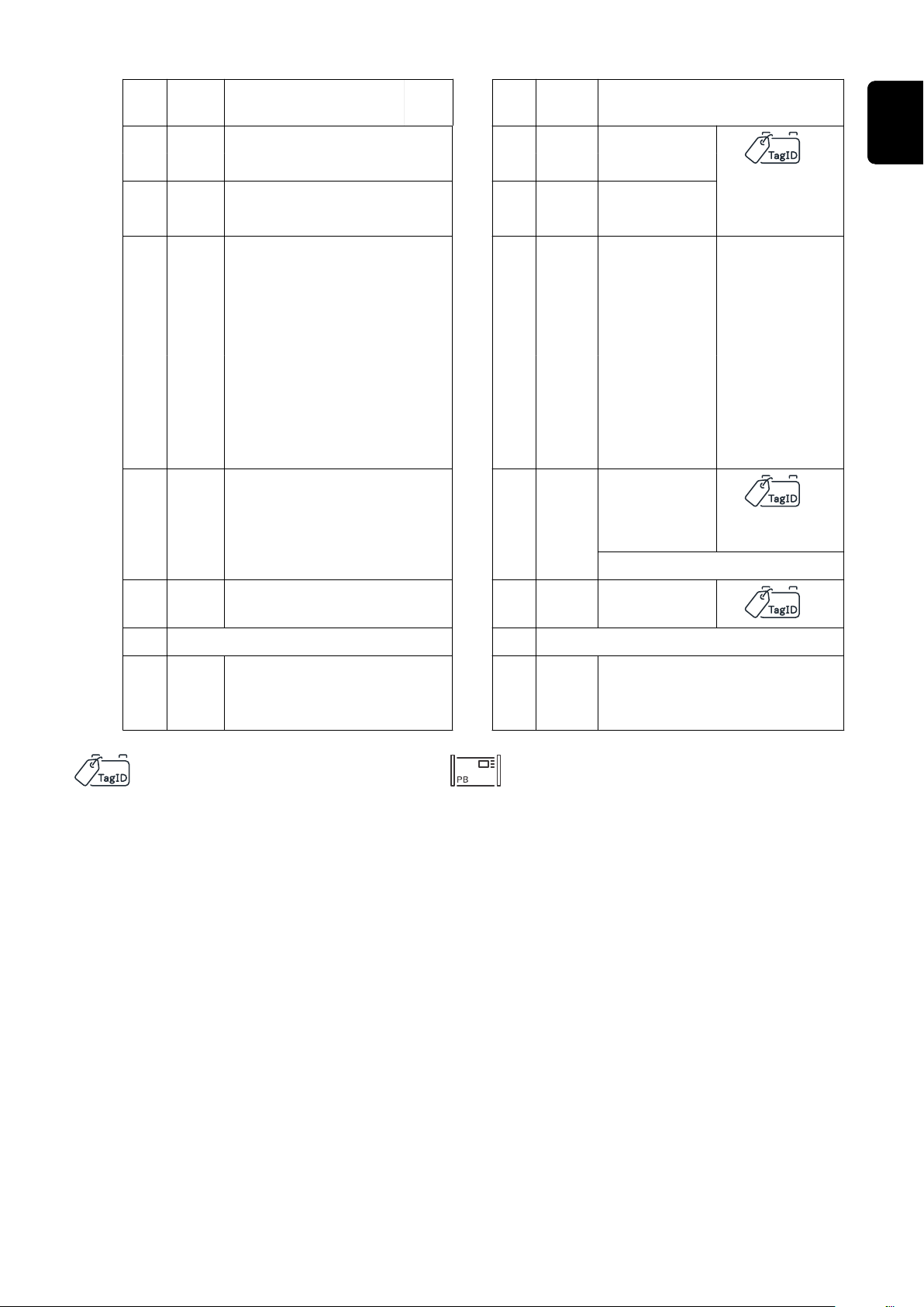
Plug
Pin
Code Function
13 S 1 Status 1 14 Dete Detect
wire white
11 S 2 Status 2 12 C2 G CAN 2 GND
wire brown
Pin
Plug
Code Function
EN
9 C1 G Remote Control wire 4
Power
7 C1 L Remote Control wire 3
wire yellow
5 C1 H Remote Control wire 2
3 4
1 - St Temperature Controlled
Option Box wire brown
CBG Easy GND
Option Box wire yellow
CBG Easy Detect
Option Box wire green
Charging
10 13 VO13 V
Supply
8 C2 L CAN 2 Low
Air Puls
6 C2 H CAN 2 High
wire green
2 + St Temperature Controlled Char-
ging
Remote Control wire 1
Option Box
wire white
CBG Easy
VCC
Status
Air Puls
TagID Link
Extern Start / Stop Extern Start / Stop
Optional for Pb Chargers
23
Page 24
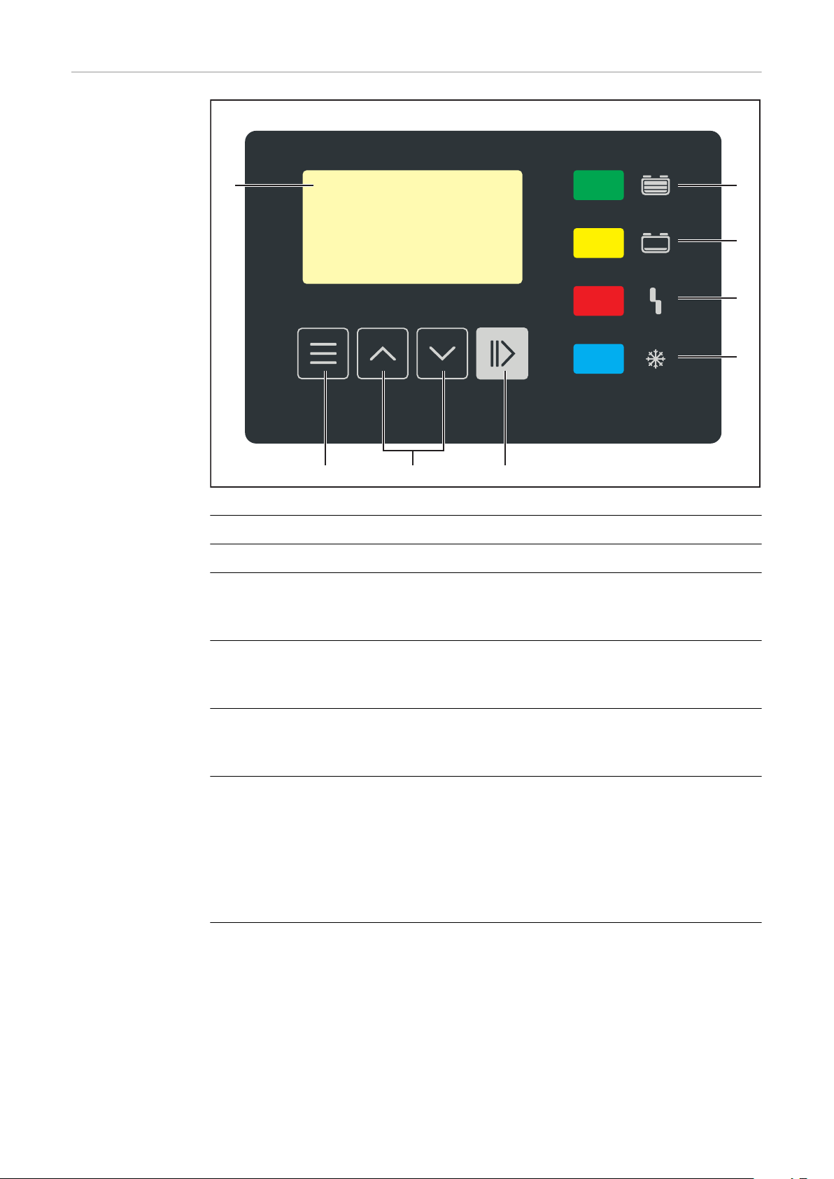
Control panel
(1) (8)
(7)
(6)
(5)
(4)(3)(2)
No. Function
(1) Display
(2) "Menu" key
Selects the desired menu.
Return to the higher-level menu.
(3) "Up/Down" keys
Selects the desired menu item.
Sets the desired value.
(4) “Pause/Start” key
For interrupting and resuming the charging process.
Confirms a menu item or setting.
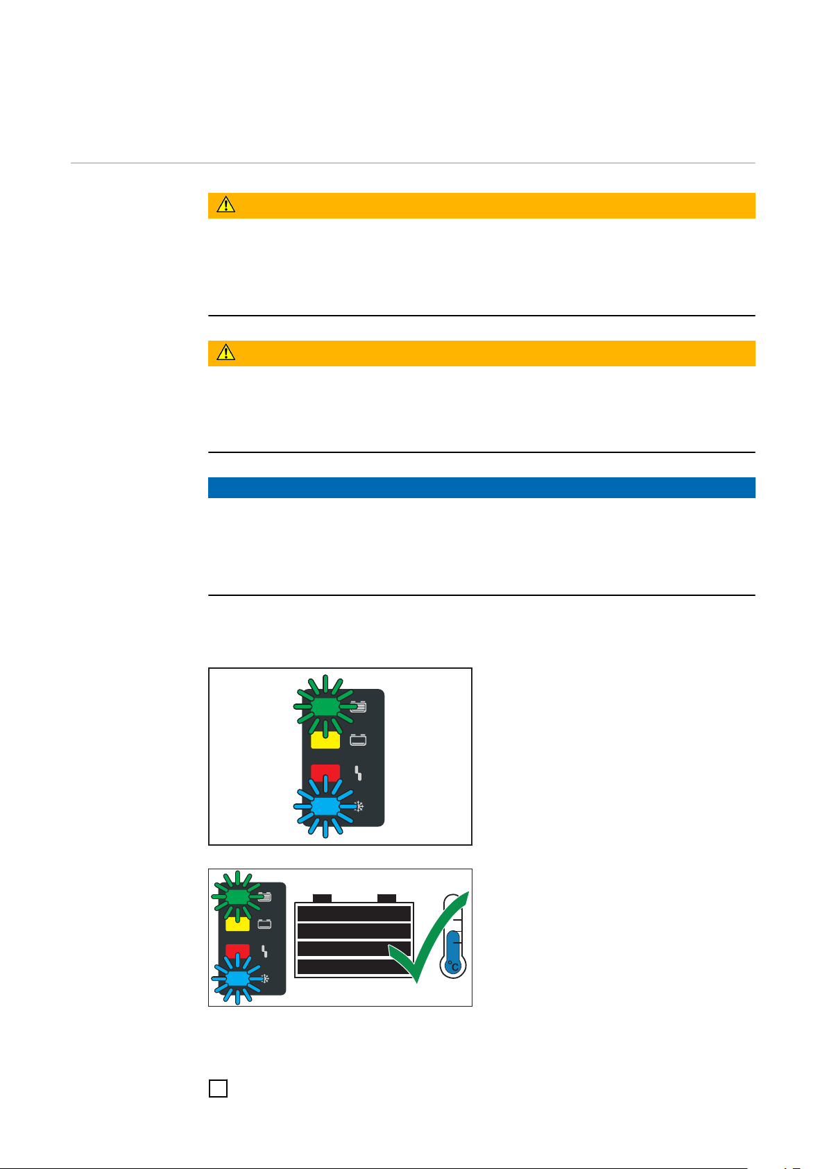
(5) "Battery cooled" indicator (blue)
Indicates a cooled battery that is ready for use.
On steady: After charging has finished, the set cooling time or optionally
the battery temperature has been reached.
Flashes every second: The water refill indicator has also tripped. More information can be found under Additional functions in the “Display”
chapter.
(6) "Fault" indicator (red)
On steady: The charger outputs an error. The current conditions do not al-
low proper charging. While the red indicator is on, charging cannot take
place (charging interrupted). The relevant status code appears on the display.
Flashes briefly every 3 seconds: The charger outputs a warning. Charging
is continued despite the adverse charging parameters. The relevant status
code and the state of charge appear alternately on the display.
24
Page 25

(7) "Charge" indicator (yellow)
Lit: during charging.
Flashes: if charging has been interrupted.
(8) "Battery is charged" indicator (green)
Lights up continuously: Charge complete.
Flashes every second: Charge complete. The water refill indicator has also
been activated. Detailed information can be found in the Additional func-
tions section of the "Display" chapter.
EN
25
Page 26
Charging the battery
Starting for the
first time
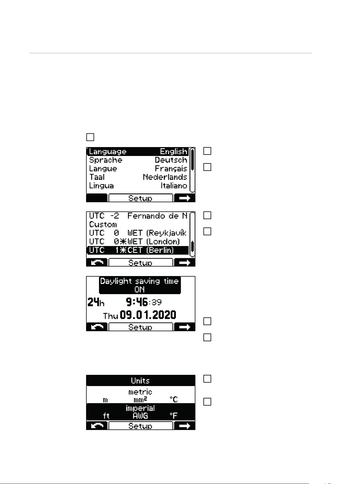
When the battery charger is connected to the grid for the first time, the device is
in SETUP mode.
In this mode, the following basic settings must be made or confirmed:
Language (English, German, French, etc.)
-
Date, time, and time zone
-
Units: metric / imperial
-
Charging cable length and charging cable cross-section
-
Type of battery, curve, number of cells, and charging time or battery capacity
-
Connect the mains plug of the battery charger to the electrical grid.
1
Use the "Up/Down" keys to select
2
the desired menu language.
Confirm with the "Pause/Start"
3
key.
English is set as the default language.
Use the "Up/Down" keys to select
4
the time zone.
Confirm with the "Pause/Start"
5
key.
UTC+1 Central European Time (Berlin)
is set as the default time zone.
The following settings must be made:
Daylight saving time ON/OFF
-
Hour format
-
Time
-
Date
-
Use the "Up/Down" buttons to se-
6
lect the desired setting.
Press the "Pause/Start" button to
7
confirm each setting.
Daylight saving time ON and the 24hour format are set as default.
Use the "Up/Down" buttons to se-
8
lect the desired setting (metric /
imperial).
Confirm with the "Pause/Start"
9
button.
26
Page 27
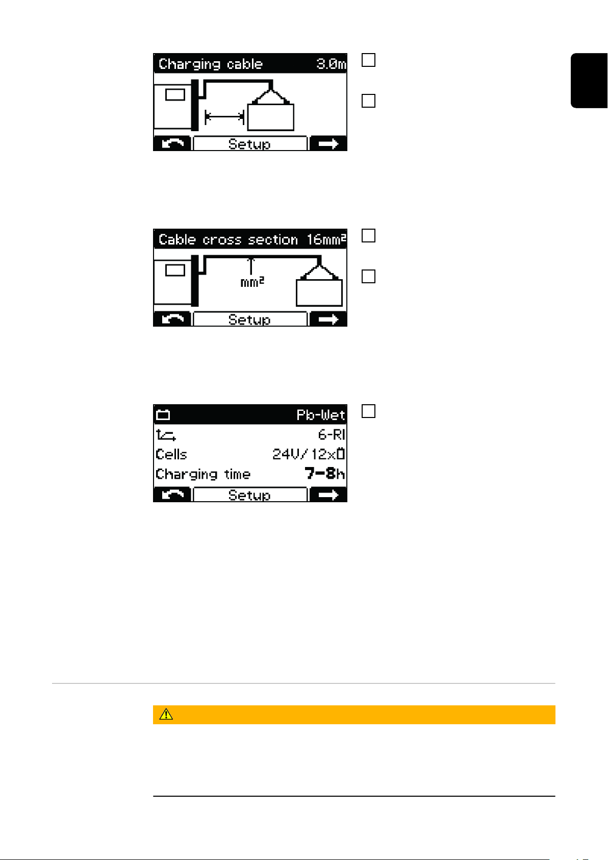
Use the "Up/Down" buttons to set
10
the appropriate charging cable
length (m / ft).
Confirm with the "Pause/Start"
11
button.
The battery charger is configured with
the correct charging cable length according to the order.
An incorrectly set charging cable
length can have a negative effect on
the charging process!
Use the "Up/Down" buttons to set
12
the appropriate charging cable
cross-section (mm² / AWG).
Confirm with the "Pause/Start"
13
button.
The battery charger is configured with
the correct charging cable cross-section according to the order.
EN
An incorrectly set charging cable
cross-section can have a negative effect on the charging process!
If the displayed charging configur-
14
ation is correct, confirm the charging configuration with the "Pause/
Start" button.
The battery charger is pre-configured
according to the order.
If the battery charger has been ordered without an additional configuration, the
following settings are set as default:
Type of battery Pb-WET (for PzS, GiS)
-
Curve 6 - RI
-
Maximum number of cells intended for the battery charger
-
Charging time 7–8 h
-
If the configuration does not match the battery used, the parameters must be
adjusted accordingly.
Detailed information on the battery charger parameters can be found in the
"Configuration mode" section of the "Display" chapter Configuration mode.
Starting the
charging process
WARNING!
Danger from leaking battery acid or explosion when charging defective batteries.
This can result in severe personal injury and damage to property.
Before starting the charging process, make sure that the battery to be
▶
charged is undamaged.
27
Page 28
WARNING!
Danger due to incorrect type of battery and incorrect charging settings.
This can result in severe personal injury and damage to property.
Before starting the charging process, make sure that the correct type of bat-
▶
tery is set on the battery charger.
The following settings must be made for the individual types of battery be-
▶
fore charging:
Charging curve
Nominal voltage (number of battery cells)
Battery capacity (Ah) or charging time (h)
Detailed information on the battery charger parameters can be found in the Con-
figuration mode section of the "Display" chapter.
CAUTION!
Danger of damage to property due to heavy contamination of the charging plug
contacts.
Due to the increased contact resistance, overheating and subsequent destruction
of the charging plug can occur.
Keep the charging plug contacts free of contamination and clean if neces-
▶
sary.
Connect the mains plug of the battery charger to the electrical grid.
1
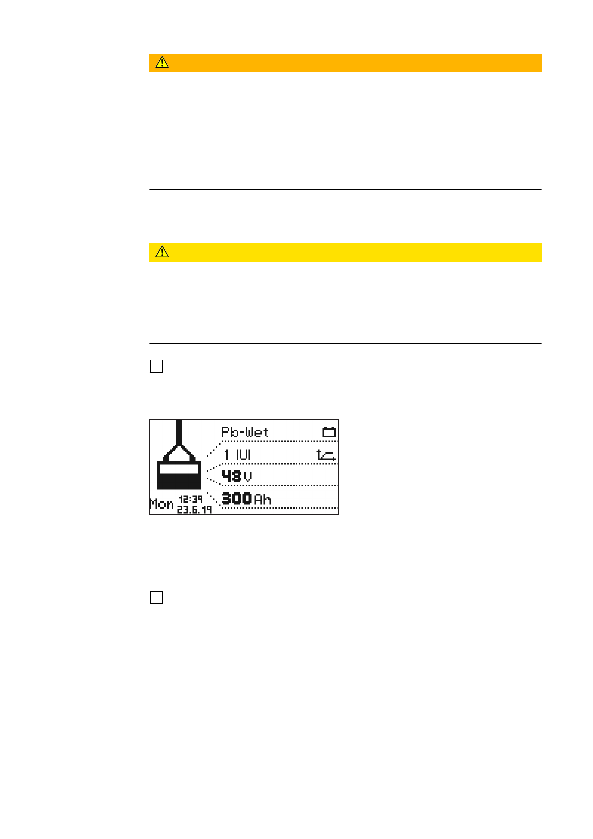
A prompt appears, asking whether the correct parameters have been set for the
battery to be charged.
The display then appears in standard
mode. The display shows the battery
charger parameters:
Type of battery (e.g., Pb-WET)
-
Charging curve (e.g., IUI)
-
Nominal voltage (e.g., 48 V)
-
Capacity (e.g., 300 Ah)
-
Weekday, time, and date
-
The battery charger parameters can be set individually. Detailed information on
the battery charger parameters can be found in the Configuration mode section
of the "Display" chapter. Make sure that the battery to be charged corresponds
to the battery charger configuration.
Plug in the charging plug.
2
The battery charger detects the connected battery and starts charging. If the
start-up delay is activated, the charging process starts after the set delay time
has elapsed. Detailed information can be found in the Configuration mode section of the "Display" chapter.
28
During the charging process the display shows the following values:
Current charging current (A)
-
Current charging voltage (V)
-
Charge delivered (Ah)
-
Battery temperature with the "Temperature-controlled charging" option
-
Time (hh:mm) from start of charge
-
Page 29
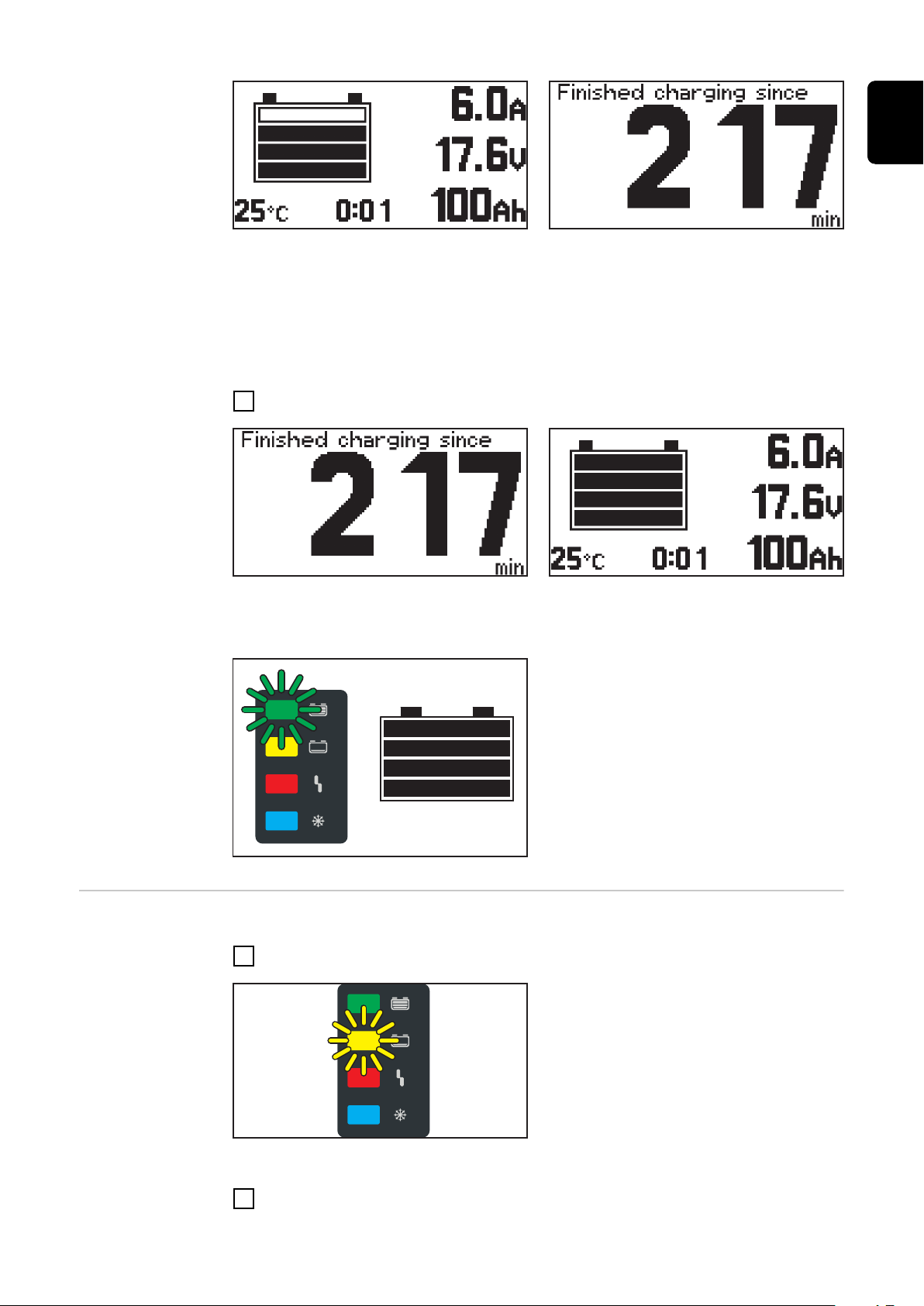
The battery symbol indicates the current state of charge. The more bars are displayed, the further the charging process has progressed. As soon as the battery
is fully charged, a minute counter appears (figure on the right). This counts the
minutes since the end of charging and makes it easier to judge which battery has
cooled down the most when using several battery chargers.
If you still want the standard display to be shown instead of the minute counter:
Use the "Up/Down" buttons to switch between the minute counter and the
1
standard display.
EN
Interrupting the
charging process
When the battery is fully charged, all 4 bars of the battery symbol appear in
black. As soon as the battery is fully charged, the green indicator lights up.
The battery is always ready for use.
-
The battery can remain connected
-
to the battery charger for any
amount of time.
The conservation charge counter-
-
acts self discharge of the battery.
To interrupt the charging process:
Press the "Pause/Start" key.
1
While the charging progress is interrupted:
The "Charge" indicator flashes (yel-
-
low).
To resume the charging process:
Press the "Pause/Start" key again.
2
29
Page 30
As long as a battery is connected to the charger, only the charging process can
be interrupted and resumed using the "Pause/Start" key. Display modes can be
changed using the "Menu" key as described in the "Display" section, but this is
only possible when no battery is connected to the charger.
Stopping charging
WARNING!
Danger due to ignition of oxyhydrogen caused by sparks generated when the
charging cables are disconnected.
This can result in serious injury and damage to property.
Before disconnecting or unplugging the charging plug, first stop the charging
▶
process by pressing the "Pause/Start" key.
WARNING!
Danger if the plug connection is disconnected during the charging process
This can result in serious injury and damage to property.
Do not disconnect the plug connection during the charging process.
▶
Do not touch live contacts on the charging plug.
▶
NOTE!
Risk of damage to the battery if it is disconnected from the charger before the
charging process is complete.
This may result in damage to the battery.
Only disconnect the battery from the charger when it is fully charged (green
▶
"Battery charged" indicator lights up).
As soon as the battery is fully charged and has cooled down, the following indicators light up:
"Battery charged" indicator (green)
-
"Battery cooled down" indicator
-
(blue)
For an optimal battery life, only disconnect the battery from the battery
charger when the blue "Battery cooled
down" indicator is showing in addition
to the green indicator, in accordance
with the explanation below. If several
battery chargers are in use, first disconnect the battery which has been
fully charged for the longest (the
coolest).
30
To stop the charging process:
Press the "Pause/Start" key.
1
Page 31

Disconnect the charging plug.
2
When the charging contacts are open, the automatic open circuit voltage detection ensures that the charging contacts are de-energised.
EN
31
Page 32
Display
Overview of display modes
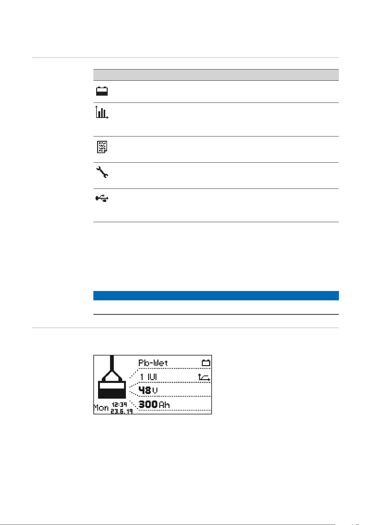
No. Function
Standard mode
In standard mode the display shows the charging parameters.
Statistics mode
Visualises the frequency of the device operating modes and shows the
total number of charging actions. Also shows an overview of the total
and average Ah produced and energy consumed per charge.
History mode
Provides information about the parameters for all the stored charging
processes.
Configuration mode
Configuration mode enables all the settings for the device and the
charging process to be adjusted.
USB mode
USB mode enables a device to be updated, device configurations to be
saved and loaded, and the charging parameters to be recorded during
the charging process - all using a USB flash drive.
As long as a battery is connected to the battery charger, the charging process
can only be interrupted and resumed by pressing the "Pause/Start" button. It is
only possible to change the display modes with the "Menu" button after disconnecting the battery from the battery charger. A detailed description of the display modes is given in the following chapter.
A limited menu selection is available while charging has been paused.
NOTE!
A limited menu selection is available while charging has been paused.
Standard mode Once the mains plug has been connected to the electrical mains supply, the dis-
play will automatically operate in standard mode.
In standard mode, the display shows
the following charger parameters:
Type of battery (e.g. Pb-WET)
-
Charging characteristic (e.g. IUI)
-
Nominal voltage (e.g. 48 V)
-
Capacity (e.g. 300 Ah)
-
Day of the week, date and time
-
The charger parameters can be set individually. More information can be found in
the "Configuration mode" section.
32
Page 33
Menu selection
Change from standard mode to the menu selection as follows:
Press and hold the "Menu" key for approx. 5 seconds.
1
Change from all other modes to the menu selection as follows:
Briefly press the "Menu" key.
1
To select the desired mode:
Use the "Up/Down" keys to select the symbol for the desired mode.
2
e.g. the battery symbol for standard mode
-
Use the "Pause/Start" key to confirm the "Tick" symbol.
3
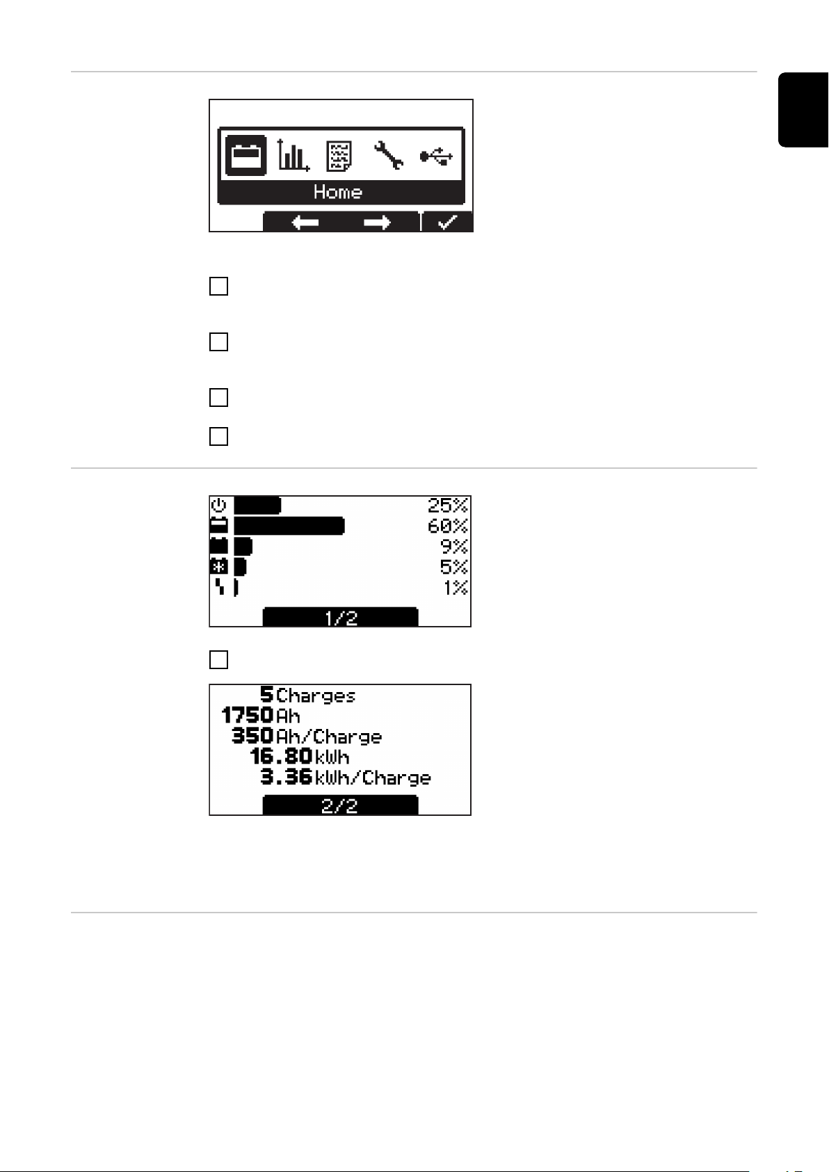
Statistics mode In statistics mode, horizontal bars dis-
play the frequency of the following
device operating statuses:
Idle
-
Charging
-
Floatingcharge
-
Cooldown
-
Error
-
EN
Use the "Up/Down" keys to toggle between page 1/2 and page 2/2.
1
Page 2/2 shows the following values:
Total number of charges.
-
Total Ah output.
-
Average Ah output per charge.
-
Total energy consumed (kWh).
-
Average energy consumed (kWh)
-
per charge.
The consumed energy display is a standard value and can deviate from the actual
amount of energy by up to 5% at nominal output. At lower power levels the deviation may be higher.
History mode History mode provides information about the parameters for all the stored char-
ging processes. In order to show changing or different displays, two versions of
the display window are shown below:
33
Page 34
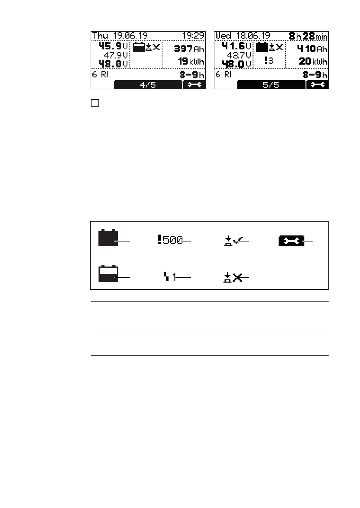
Use the "Up/Down" keys to switch between the pages for each stored char-
(1)
(2)
(3)
(4)
(5) (7)
(6)
1
ging process.
Contents of the display window
Charge start date, e.g.: Thursday, 19/06/14.
-
Charge start time, e.g.: 19:29 or charging time, e.g.: 8 h 28 min.
-
Voltage at charge start, e.g.: 45.9 V.
-
Voltage after 5 minutes, e.g.: 47.9 V.
-
Voltage at charge end, e.g.: 48.0 V.
-
Ah consumed, e.g.: 397 Ah.
-
kWh consumed, e.g.: 19 kWh.
-
Charging characteristic, e.g.: 6 RI.
-
Set charging time, e.g.: 8 - 9 h or set Ah, e.g.: 400 Ah or set charge end time
-
(not shown).
Symbols shown
No. Function
(1) Full battery
Charging has been completed.
(2) Empty battery
Charging has not been completed.
(3) Exclamation mark with number
Warning issued, with code for the corresponding status code. Detailed information can be found in the Status codes section.
(4) Symbol with number
Error issued, with code for the corresponding status code. Detailed information can be found in the Status codes section.
(5) Key symbol with a tick
Charging was stopped properly using the "Pause/Start" key.
34
Page 35
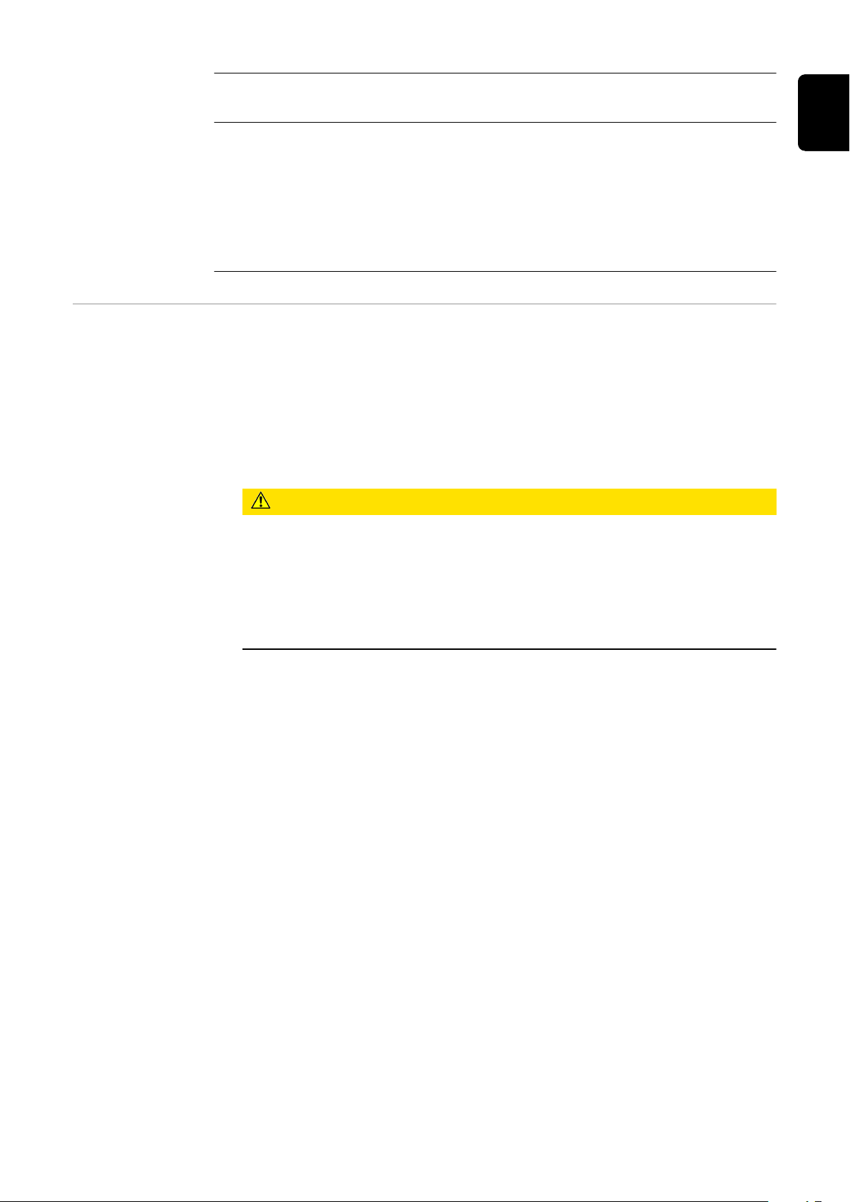
(6) Key symbol with a cross
Charging was stopped without using the "Pause/Start" key.
(7) Charging details
Displays certain battery data at the beginning and end of the charging
process:
Number of cells
Ah
Characteristic
Type of battery
EN
Configuration
mode
Configuration mode provides the following setting options:
"Charging settings": settings for the battery
Type of battery, e.g. "Wet".
-
Charging characteristic, e.g. "IU".
-
Capacity (Ah) or charging time (h) depending on the charging characteristic.
-
Cells: voltage (V) and number of battery cells or automatic setting of the
-
number of cells.
CAUTION!
Danger of damage to the battery.
This may result in damage to the battery.
The number of cells should only be set automatically for batteries with
▶
the following nominal voltages: 12 V and 24 V for 24 V devices, 24 V and
48 V for 48 V devices.
Do not set the number of cells automatically for deep discharged batter-
▶
ies.
Additional settings:
-
for individual adaptation options for the charging characteristic.
"Additional functions": Additional functions
Blue LED
-
External start/stop
-
Refill indicator
-
Options area
-
Start charging again after a grid failure
-
"General options": General settings
Language
-
Contrast
-
Time (hh:mm:ss)
-
Time zone
Daylight saving time/normal time
Date (dd:mm:yy)
-
Length of charging cable (m)
-
-
Charging cable cross section (mm2)
AC current limitation
-
Unit for temperature values
-
Code for accessing the configuration menu activated/deactivated.
-
Time interval for the parameters recorded on the USB flash drive (s).
-
Reset statistics
-
Reset history
-
35
Page 36
“Reset Settings”
Includes a double-check prompt ("OK?") that requires the operator to recon-
-
firm that this step is intended.
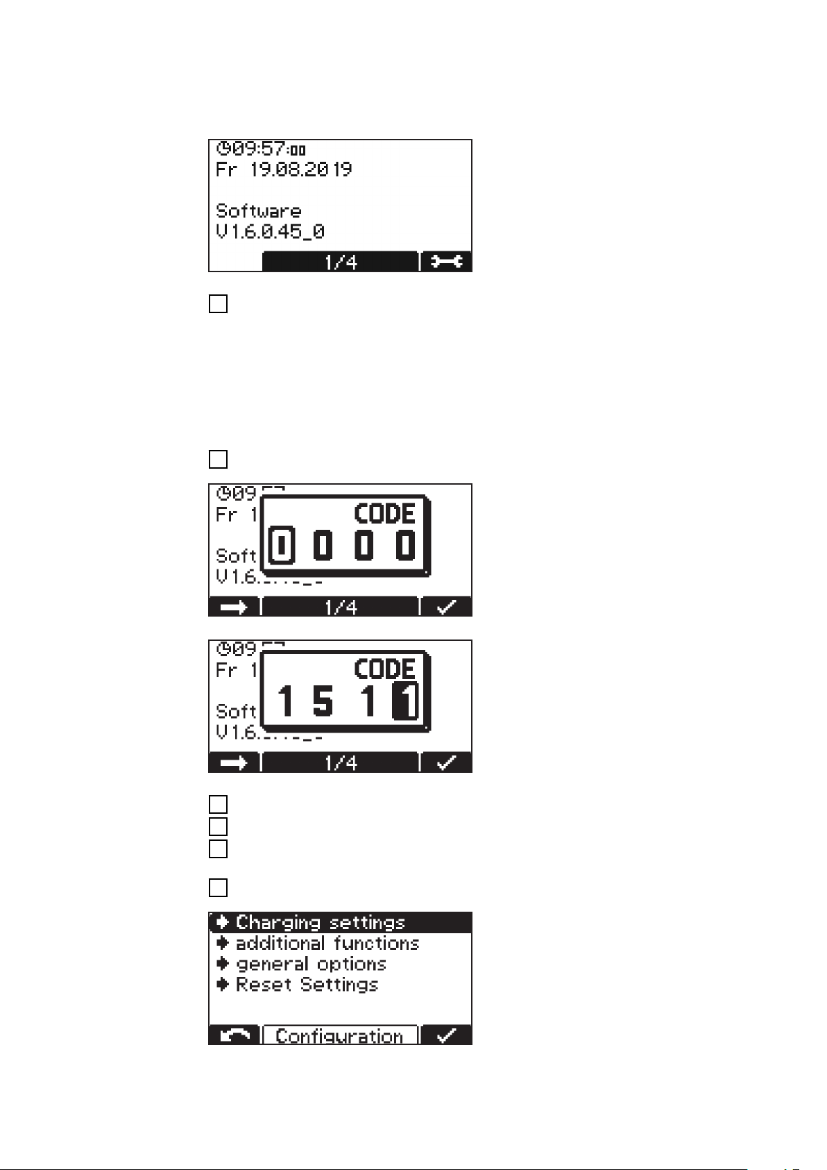
First the screen will appear in its initial
format, showing the date, time and
software version.
The "Up/Down" keys can be used to retrieve the following information:
1
Serial number of the charger plus serial number and version of the con-
-
figuration memory.
PC board for controller/power electronics: hardware version and serial
-
number.
Software: main software, secondary software, primary software and char-
-
acteristic block version.
The procedure for opening the configuration menu is as follows:
Press the "Pause/Start" key.
1
You will be prompted to enter a code.
The code required is "1511" and is
entered as follows:
Using the "Up/Down" keys, enter the first digit of the code.
1
Press the "Menu" key to move to the next digit of the code.
2
Continue following the procedure described above until the complete code
3
has been entered.
Use the "Pause/Start" key to confirm the code entered.
4
36
You will now be prompted to select
one of the main menu items for the
configuration mode.
Page 37
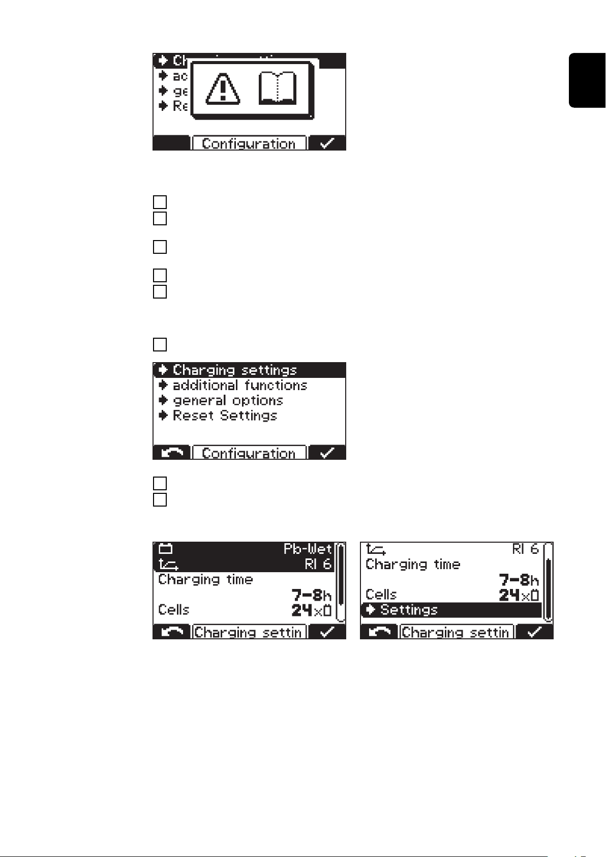
When you select a menu item you may
be presented with a prompt to read
the Operating Instructions. Confirm
this prompt by pressing the "Pause/
Start" key again.
The procedure for navigating the configuration menu and its submenus is as follows:
Use the "Up/Down" keys to select the desired menu item.
1
Use the "Pause/Start" key to confirm the menu item, and reconfirm any
2
double-check prompt (e.g. "OK?").
Use the "Up/Down" keys as necessary to choose an item, e.g. "Off/On" or
3
enter a value.
Use the "Pause/Start" key to confirm what you have entered.
4
If the cursor moves to another setting or position after confirmation of the
5
previous setting, repeat the procedure described in points (3) and (4).
To exit the current menu:
Press the "Menu" key to return to the higher-level menu.
6
EN
See the following explanation of how
to set the charging settings by way of
example:
Use the "Up/Down" keys to select the "Charging settings" menu item.
1
Use the "Pause/Start" key to confirm this menu item.
2
The choice of settings for the "Charging settings" menu item will now be displayed:
the display may vary depending on the selection made. If the "Pb-WET" type of
battery has been selected in combination with the "RI" characteristic ("Curve") as
in the example here, the "Ah" heading is replaced by the "Charging time" setting
option.
Both the start and end time can be set for this charging time period. The starting
time can be deselected as required; the charging time then bases itself exclusively on the specified charge end time following a manual charge start.
When applying the settings, the user will be guided through the menu in much
the same way as a wizard function.
37
Page 38
Use the "Up/Down" keys to select the desired parameter (e.g. "Cells").
3
Use the "Pause/Start" key to confirm the parameter.
4
Use the "Up/Down" keys to set the desired value (e.g. "24" for the number of
5
battery cells).
Use the "Pause/Start" key to confirm what you have entered.
6
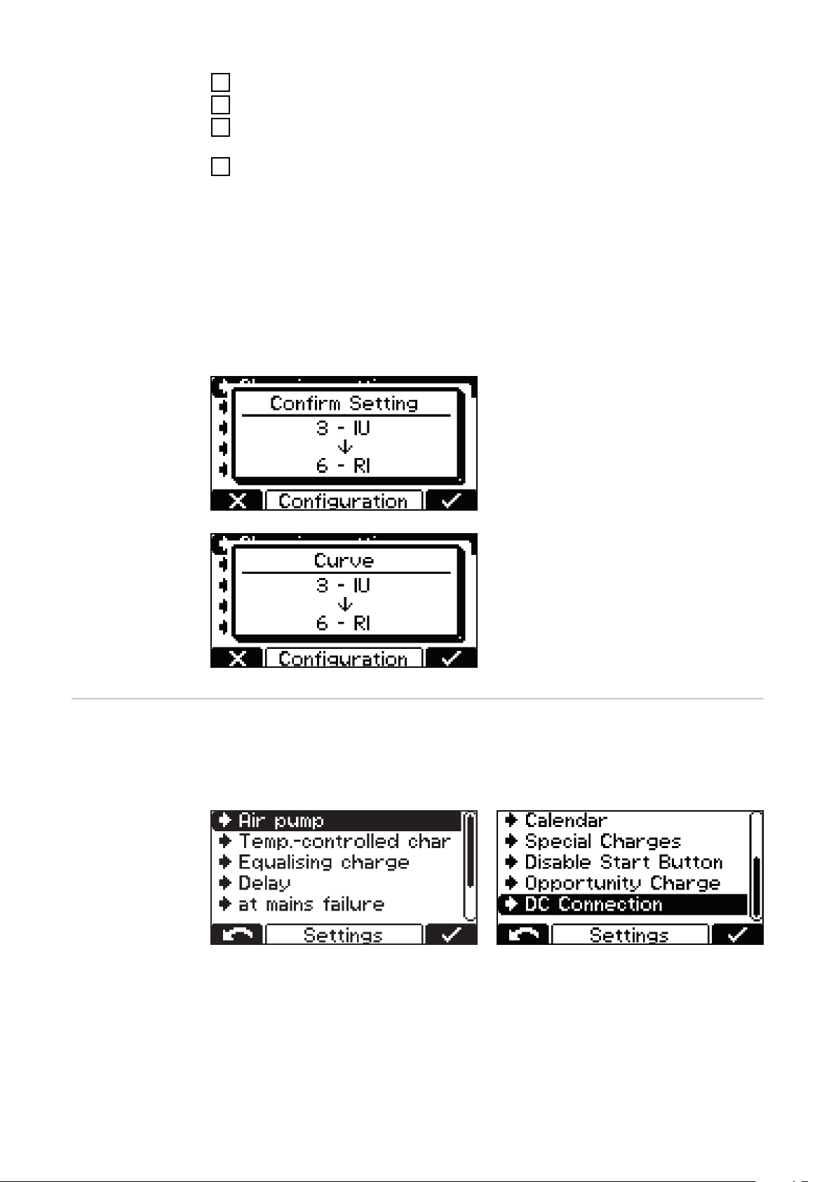
If one or more relevant settings are changed for the charging process in configuration mode, you will once again be prompted to confirm acceptance of the
changed settings when exiting configuration mode.
The following settings need to be confirmed when exiting configuration mode:
Characteristic
-
Battery capacity in Ah (excluding the RI characteristic)
-
Number of cells
-
Equalising charge ON/OFF
-
CAN protocol
-
Example:
Changing the characteristic from 3 UI (Pb-WET) to 6 - RI (Pb-WET).
Overview of
charging settings
If the setting is not confirmed, the
charger returns to configuration mode
and the setting can be changed to the
desired value.
Below is a detailed explanation of the "Settings" menu item, selected under the
aforementioned "Charging settings" menu item. Navigation is carried out as described in the Configuration mode section.
A list appears with the following selection options:
38
The individual selection options are explained in greater detail below.
Page 39
Electrolyte cir-
Program ON 1 OFF 1 Repeat ON 2 OFF 2
1 30 min 25 min 1 x 5 min 25 min
2 3 min 10 min 4 x 3 min 20 min
3 3 min 12 min 1 x 3 min 12 min
4 5 min 10 min 3 x 5 min 20 min
5 2,5 min 7,5 min 1 x 2,5 min 7,5 min
culation
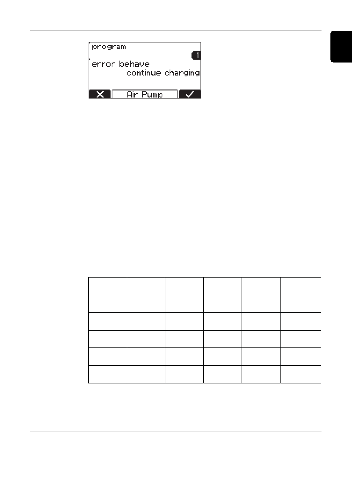
"Air Pump" electrolyte circulation (not
available on the Selectiva 220 V variant):
The electrolyte circulation cycle is
controlled by the charger's control
system. A number of selection options
are available for this purpose.
The following settings are available for electrolyte circulation:
Off
Electrolyte circulation switched off.
-
Continuous operation (“continuous”)
Electrolyte circulation permanently on.
-
Program 1 to 5
Default electrolyte circulation programs and their relevant parameters can
-
be found in the table under "Settings" in the "Display" chapter.
Automatic
Automatic adjustment of the electrolyte circulation flow rate based on the
-
set battery parameters.
EN
User - “On”/”Off”
Individual setting of the electrolyte circulation.
-
The settings for "On" and "Off" determine the pulse/pause ratio of the air
-
flow intervals.
Default electrolyte circulation programs and their relevant parameters can be
found in the table below:
In each of these programs, the solenoid valve opens for a time "ON 1" and closes
for a time "OFF 1". This process is repeated for the number of times specified
under "Repeat". After this number of repetitions has been completed, the process continues with the "ON 2" and "OFF 2" times until charging is completed.
Temperaturecontrolled charging
Temperature-controlled charging:
39
Page 40
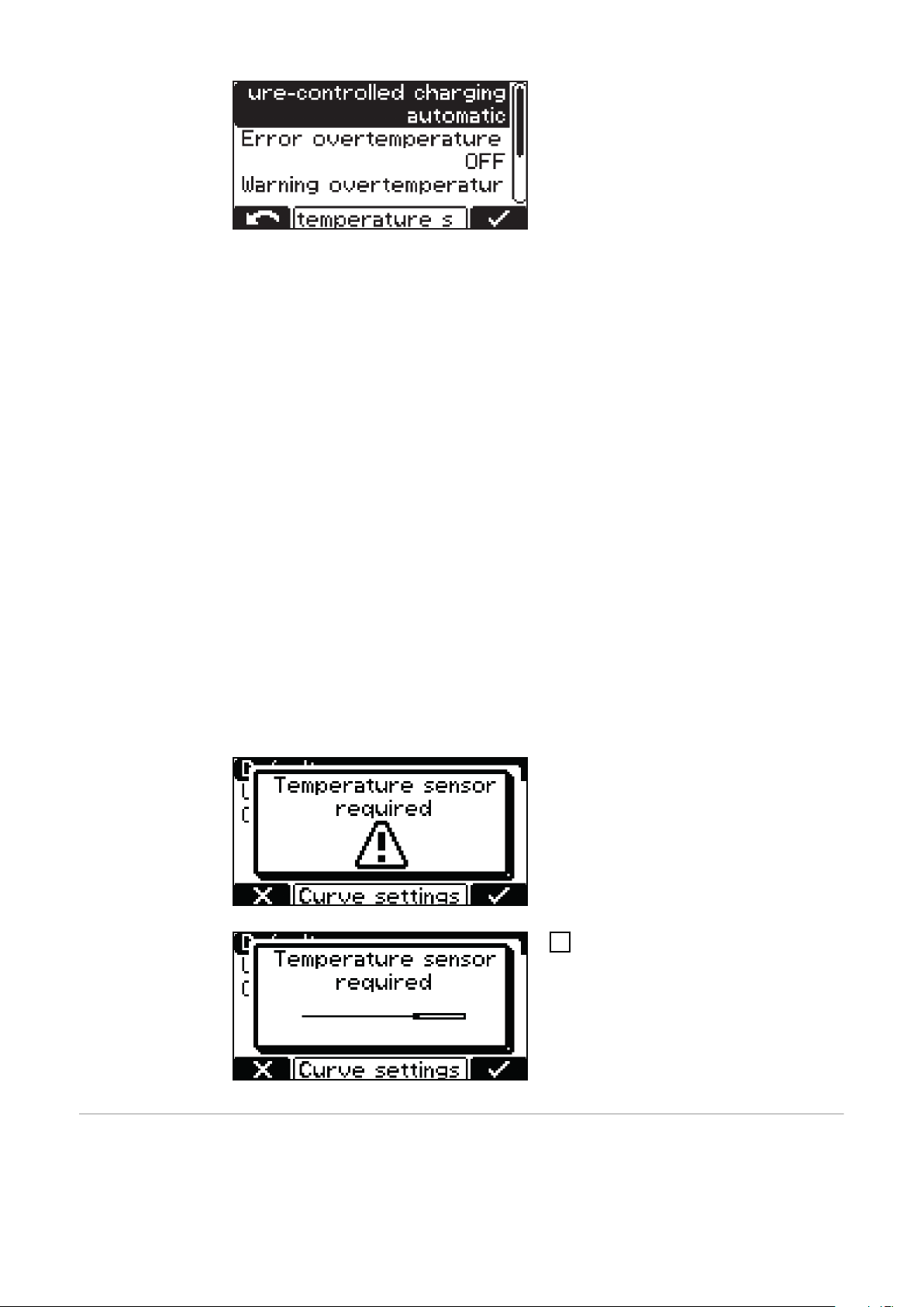
The following settings are available for temperature-controlled charging:
automatic/OFF/required
automatic ... Temperature-dependent adjustment of the charging character-
-
istic.
OFF ... The measured battery temperature is not taken into account.
-
required ...
-
Charging only starts if the temperature sensor is connected.
Error overtemperature ON/OFF
ON ... Error message in the event of battery overtemperature.
-
Charging process stops and can only be continued once the battery has
cooled down and been reconnected.
OFF ... No error message in the event of battery overtemperature.
-
Warning overtemperature ON/OFF
ON ... Warning in the event of battery overtemperature.
-
OFF ... No warning in the event of battery overtemperature.
-
An external temperature sensor is required for certain characteristics. If this
type of characteristic is selected in configuration mode, a note is shown indicating that an external temperature sensor is required.
The following characteristics require an external temperature sensor:
28 - FCC IUI - CSM WET
-
30 - FCC IUI - WET
-
Equalising
charge
Equalising charge
OFF
There is no equalising charge.
-
A note is displayed if a characteristic
that requires an external temperature
sensor is selected.
Use the "Pause/Start" key to con-
1
firm the note.
40
Page 41
Delay
If the battery remains connected to the charger for the duration of the
-
equalising charge delay ("equalize charge delay"), a special type of charging
takes place. This prevents acid stratification.
The parameters for the current (ampere/100 ampere hours), voltage (volt/
-
cell) and duration of the equalising charge may all be changed.
Weekday
Specify the weekday on which the equalising charge is to take place.
-
The parameters for the current (ampere/100 ampere hours), voltage (volt/
-
cell) and duration of the equalising charge may all be changed.
Manual equalising charge (“Manual”)
An equalising charge can be started manually by pressing the relevant key on
-
the display.
The equalising charge starts after a set delay time has been observed. The
-
charge parameters that have been set are followed.
The parameters for the current (ampere/100 ampere hours), voltage (volt/
-
cell) and duration of the equalising charge may all be changed.
This function is only available for Pb-Wet characteristics.
-
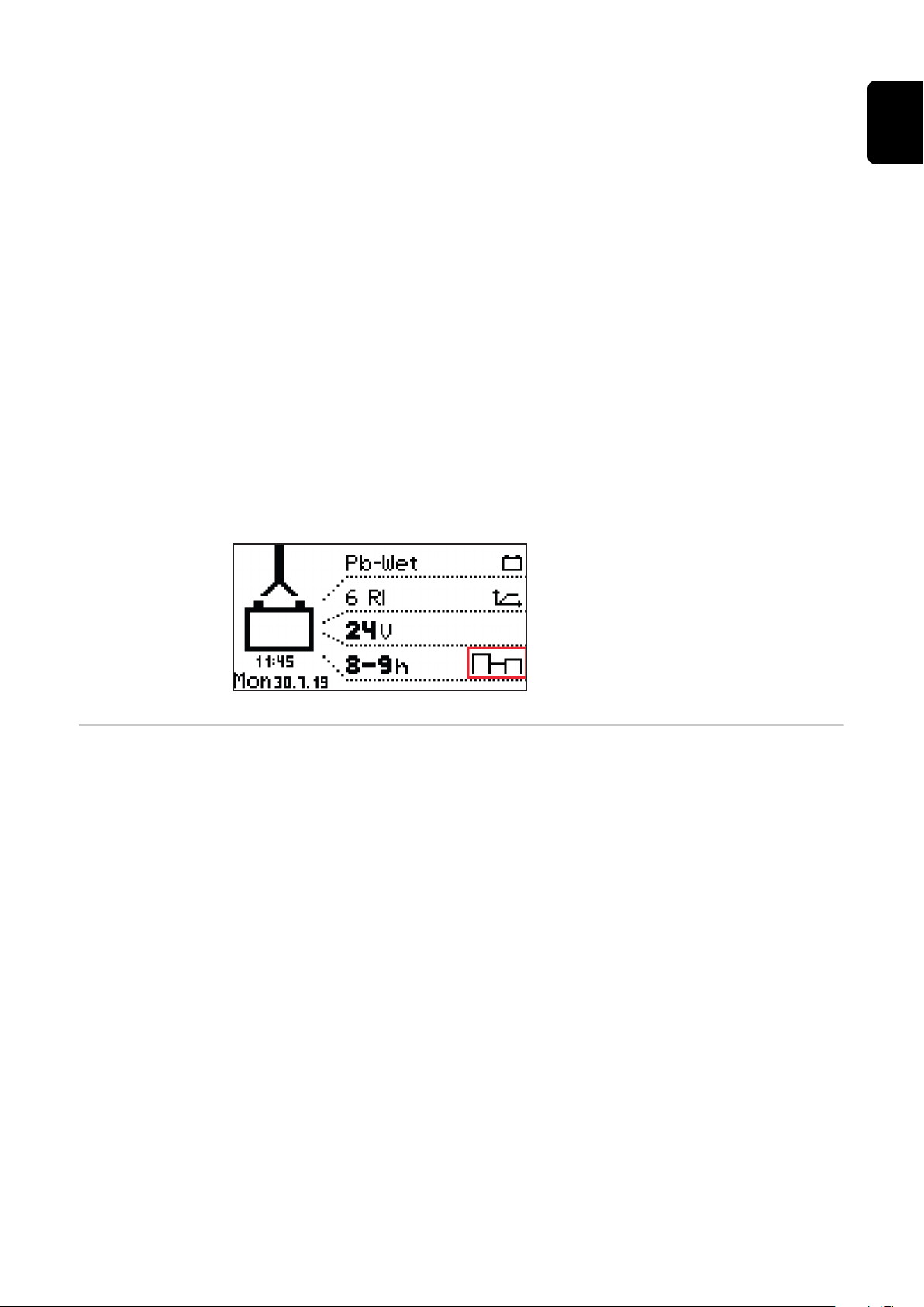
If a setting for the equalising charge is enabled, a symbol on the home screen
next to the set ampere hours or charging time shows whether an equalising
charge is being carried out or can be started.
EN
Delay "Delay"
"Charge start delay"
Delay time (minutes) between the activation time of the charge start and the
-
actual charge start.
“Charge end delay”
Delay time (minutes) between the signaled end of charge (e.g. green indicat-
-
or) and the actual end of charge.
"At mains failure restart charging"
If this option is activated, the charging process is automatically restarted
-
after a fault in the electrical network as soon as the electrical network is
available again.
"At mains failure"
Restart charging
-
Automatic/continue charging
-
If the "Restart charging" option is activated, the charging process is automatically restarted after a fault in the electrical network as soon as the electrical network is available again.
41
Page 42
If the "Automatic/continue charging" option is activated, the charging process is
automatically continued after a fault in the electrical network as soon as the
electrical network is available again.
Calendar Calendar
The calendar function allows charging to be started automatically according to
the following criteria:
Time window in which charging may not be started if a battery is connected.
-
Time window in which charging is to be started using a defined characteristic
-
1 if a battery is connected.
Time window in which charging is to be started using a defined characteristic
-
2 if a battery is connected.
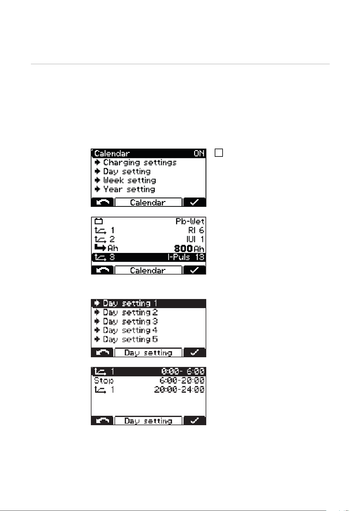
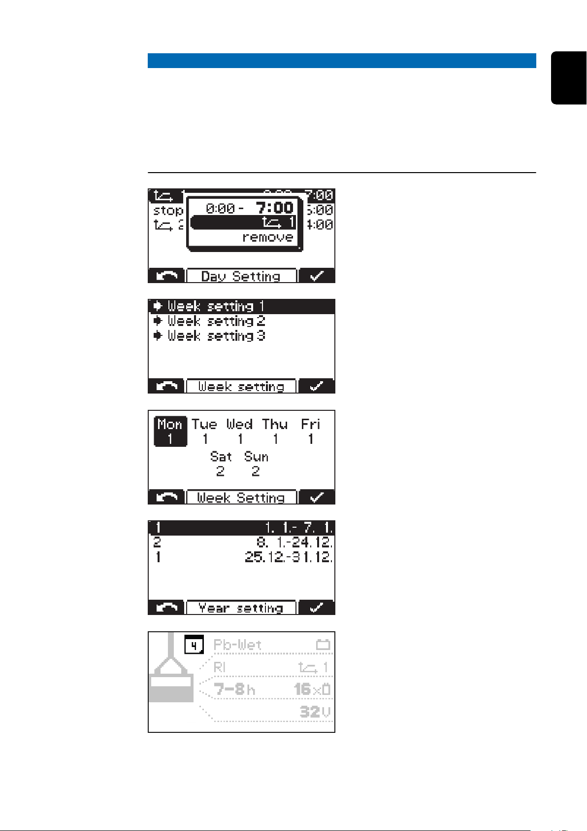
To activate the calendar function,
1
select the "ON" setting and confirm.
"Charging settings" menu item:
Type of battery for every charac-
-
teristic:
e.g. Pb-WET.
Curve settings when selecting the
-
relevant characteristic.
Additional settings can be found under the "Calendar" function:
Day Setting 1-5:
The day settings allow up to five different charging start time profiles to be
defined with the following settings:
Symbol for characteristic 1:
-
Time window in which charging is
to be started using characteristic 1
(e.g.: 00:00-06:00)
Stop:
-
Time window in which charging
must not take place (e.g.:
06:00-20:00)
Symbol for characteristic 1:
-
Time window in which charging is
to be started using characteristic 1
(e.g.: 20:00-24:00)
42
Page 43
NOTE!
Ongoing charging operations are unaffected by the set time windows.
If, in the example above, a battery is connected at 05:45, the charge end
▶
time is governed according to need and is not interrupted by the end time
specified for the set time window (06:00 in the example).
If the battery is connected during the "stop" time window, charging is started
▶
automatically during the next time window. If charging is started manually
during the "stop" time window, charging will always take place using characteristic 1.
Additional settings:
Change the allocated characterist-
-
ic:
characteristics symbol.
Remove the selected characterist-
-
ic:
"remove".
Week Setting:
Three different week settings can
-
be defined.
EN
A previously created day setting can be
assigned to any day of the week.
Year Setting:
Multiple periods throughout the
-
year may be defined, each containing a single week setting (e.g. 1/1 7/1).
When the calendar function is active, a
calendar symbol (shown here with the
number "4" as the current date) appears on the display.
43
Page 44
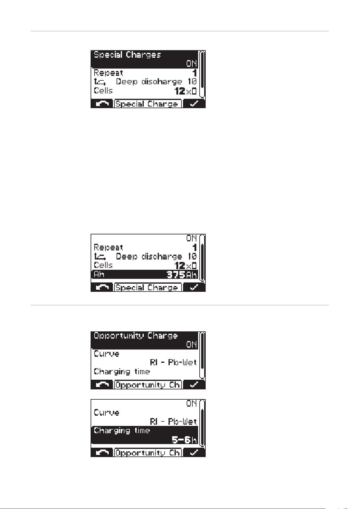
Special charges Special Charges
The "repeat" setting defines how often the alternative charging mode should be
performed until the device reverts to the original charging parameters again:
Setting range
1 to 99 repetitions
-
Disable Start Button
ON
The charging process cannot be started using the "Pause/Start" key, e.g. to
-
prevent unauthorised intervention.
OFF
The charging process can be started using the "Pause/Start" key.
-
Selecting "Special Charges" allows one
or more of the alternative charging
types to be performed temporarily.
“Opportunity
Charge” special
function
"Opportunity Charge” special function:
The following settings are also possible:
Characteristic:
-
e.g. "Deep discharge 10"
Number of battery cells:
-
"Cells" - e.g. 12x
Battery capacity in Ah:
-
e.g. 375 Ah
To extend the usage interval of a battery, it is possible to recharge it at a
time when it will not be needed, e.g.
during scheduled plant shutdowns.
The following curve settings are available:
-
Curve - e.g. RI - Pb-WET
-
Charging time - e.g. 5 - 6 h
44
Page 45
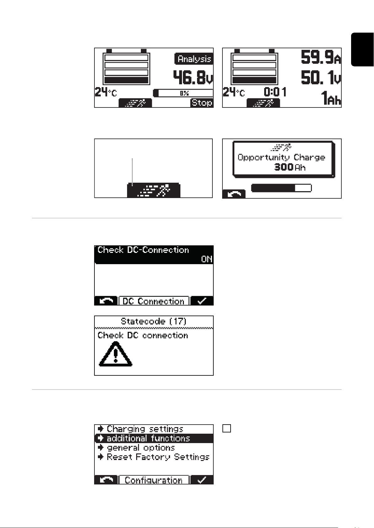
When opportunity charging is "ON" and a battery is connected, the following ap-
(1)
pears:
Display when RI characteristic is selected Display for other characteristics (e.g. IUI)
To start opportunity charging:
Use the "Up" key to select the runner symbol (1).
-
EN
"Runner symbol" (1)
DC connection DC Connection:
Display when opportunity charging starts
The “DC Connection” menu contains
the setting for the DC connection
check.
If the DC connection check is switched
on (“ON”), the connection between the
charger and the battery is checked
during the charging process.
If problems arise with the DC connection during the charging process,
status code 17 is set if the DC connection check is active.
A connection problem can occur if, for
example, charging contacts are worn or
dirty.
Additional functions
Detailed description of the "additional functions" menu item in configuration
mode. Navigation is performed as described in the "Configuration mode" section.
Select the "additional functions"
1
menu item.
45
Page 46
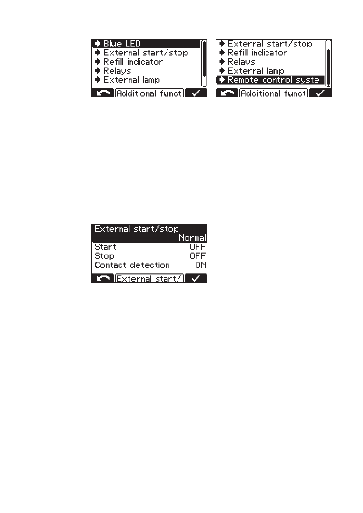
A list appears with the following selection options:
The individual selection options are explained in greater detail below:
Setting the "Blue LED" indicator
Time (minutes) that must be allowed to pass before the blue "battery cooled" indicator comes on to indicate that a battery has cooled down sufficiently. The
time from the end of charging is used as the setting.
A temperature value can be set here in conjunction with the "Temperature-controlled charging" option. The blue "battery cooled" indicator will light up to signal
a sufficiently-cooled battery once the temperature drops below this value.
External start/stop
The following settings are available when external start/stop is selected:
Button
The function of the "OK/STOP" key can be simulated using an external but-
-
ton.
Normal
Start ON
-
Charging starts when an external switch is closed and a battery is detected,
or when the charging plug is connected by closing the auxiliary contacts and
a battery is detected.
Start OFF
-
Charging starts when a battery is connected.
Stop ON
-
Charging is interrupted when an external switch is opened,
or when the charging plug is disconnected by opening the auxiliary contacts.
Stop OFF
-
Opening of an external switch or the auxiliary contacts is ignored.
46
Page 47
Contact detection
ON
-
When Start Normal is ON, a battery is connected and the external start/stop
contact is not closed, error 16 is set.
When Stop Normal is ON, charging has started, the external start/stop contact is open and the battery is not disconnected, error 16 is set.
OFF
-
Contact detection does not take place.
Refill Indicator
The refill indicator is a message that appears as soon as the battery needs topping up with distilled water. The time at which refilling is deemed necessary can
be defined as follows:
Every nth week and weekday
e.g. top up with water every fortnight on a Friday
-
If set to "OFF", the refilling request does not have to be confirmed.
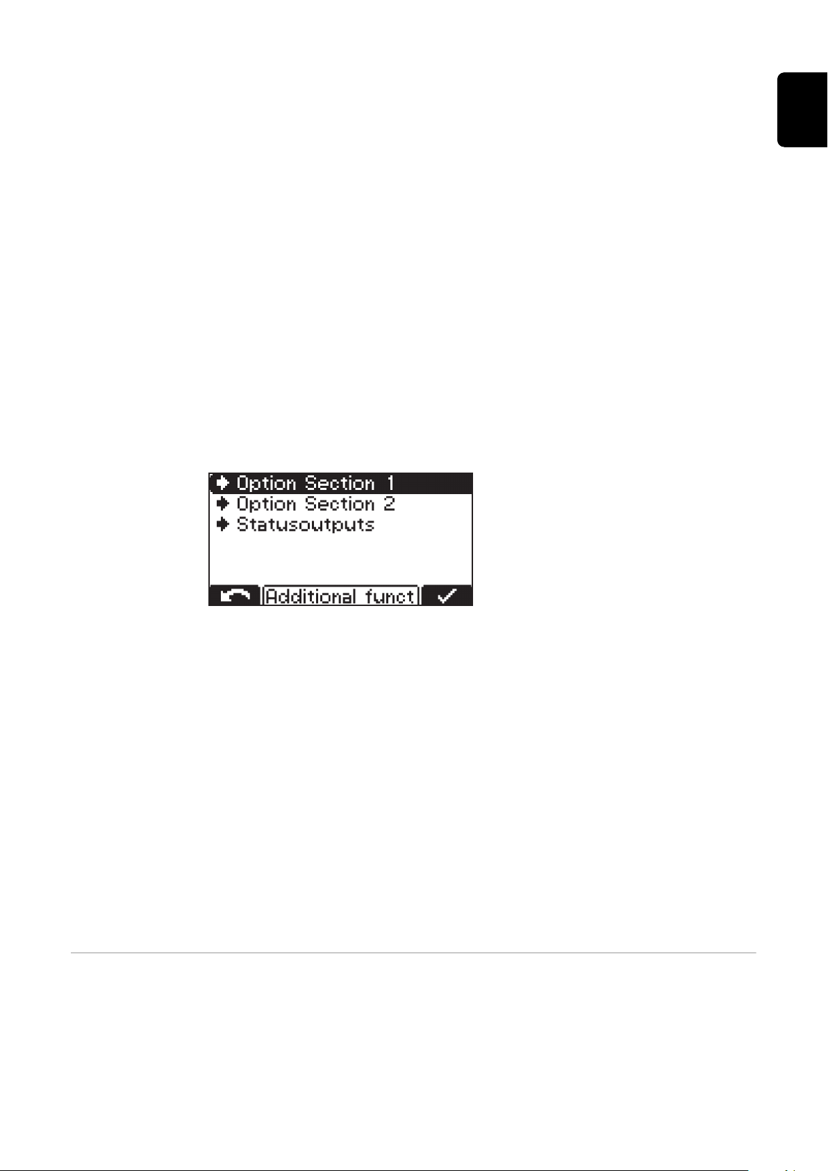
Option Section
EN
Option Section 1
Setting options:
-
CAN1 (option box)
Cool Bat Guide Easy (Fronius variants only)
Option Section 2 (3 kW only)
Setting options:
-
CAN2 (option box)
AirPuls (EUW)
Status outputs (3 kW only)
Setting for external lamp (normal or RGB)
-
At mains failure restart charging
If this option is selected, the charging process is restarted automatically as soon
as the mains supply becomes available again after a disruption to the electrical
mains supply.
General settings Detailed explanation of the "general options" menu item in configuration mode.
47
Page 48
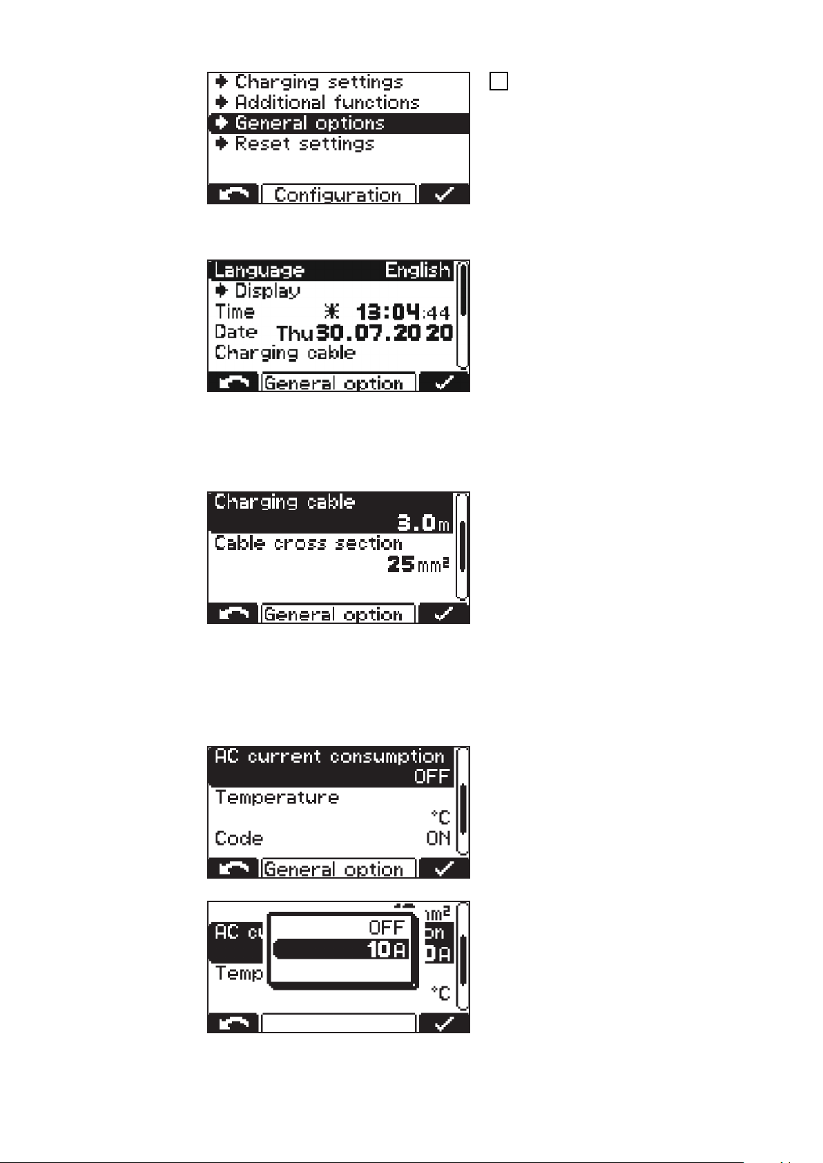
Select the "general options" menu
1
item.
A list appears with the following selection options:
Language
-
Display settings
-
-
-
-
Time and Date
-
-
-
-
Charging cable:
Contrast
LED brightness
Show Ah at charge end
ON/OFF
daylight saving time / normal
time
Predefined time zones
User-defined time zones
Cable cross section:
Cross-section of the charging cable (mm²)
-
AC current consumption:
Basic length of charging cable (m)
-
Adapt the maximum consumed
-
device current to the on-site electrical installation or the device
connector fitted on the device.
48
The minimum and maximum values
-
differ depending on the different
device classes. The minimum value
is approx. 25% of the maximum
nominal current of the charger.
Page 49
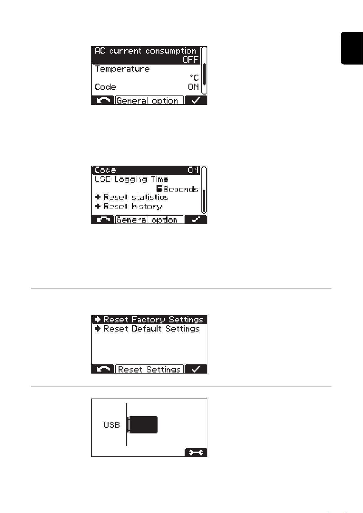
Temperature:
Temperature in °C / °F
-
Code:
Code entry required / not required to access configuration mode ("Code
-
ON / OFF")
USB Logging Time:
Time interval (s) for recording
-
charging parameters on the USB
flash drive (USB Logging Time)
EN
Reset statistics
Reset history
For more detailed information on the statistics and history, please refer to the
"Statistics mode" and "History mode" sections.
Reset settings The menu item offers 2 possibilities to reset all settings made:
Reset Factory Settings:
Resets to factory settings.
-
Reset Default Settings:
Resets settings to the manufac-
-
turer's defaults.
USB mode In USB mode, the display shows
whether a USB thumb drive is plugged
in.
The USB thumb drive must meet the
following specifications:
Formatting: FAT32
-
32 Gigabyte maximum
-
No multiple partitioning
-
49
Page 50

The I-SPoT-VIEWER software (www.fronius.com/i-spot) supports the visualiza-
tion and evaluation of the data on the USB thumb drive.
To start a data download, confirm this again with the "Pause/Start" button. If this
repeated confirmation with the "Pause/Start" button is not carried out, the
download starts automatically after one minute.
While a charging process is in progress, the USB thumb drive may be connected
after pressing the "Pause/Start" button. It is only possible to read data and not to
perform an update or load a configuration.
Safely remove
Safely remove the USB thumb drive once the desired action is complete.
-
Update
A list of suitable update files stored on the USB thumb drive opens.
-
The desired file is selected and confirmed in the same way as scrolling
-
through the settings.
Do not rename the automatically assigned file name of the update file!
-
The latest firmware is available in the download area of the Fronius website.
-
Firmware installation instructions are included in the zip file of the down-
-
load.
Download
The data of the logged charging parameters stored in the datalogger of the
-
device are saved for the I-SPoT VIEWER on the USB thumb drive.
Events as well as device settings and user curves (configuration) are also
-
saved.
The following time ranges can be selected for the data logger:
-
1 month
3 months
All
Since last time
Download optional
The following options are available:
I-SPoT VIEWER
-
The logged data is saved in the same way as for the "Download", but only with
the data for the I-SPoT VIEWER.
Save data logger
-
The logged data is saved in the same way as for the "Download", but as "csv"
files rather than in the I-SPoT VIEWER format.
(Automatically created folder structure for the ".csv" files: *
Fronius\<Device serial number>\Charges\<yyyymmdd>\<hhmmss.csv>)
Save events.
-
Events are saved on the USB thumb drive.
Save configuration.
-
The device settings are saved on the USB thumb drive.
Load configuration
Loads a suitable device configuration stored on the USB thumb drive into the
-
device.
Load dealer text
Here a text file can be loaded from the USB thumb drive, which is displayed
-
as soon as the device is in an error state.
The text file can contain the contact details of the distributor, for example.
-
The file must be saved on the USB thumb drive in the ".txt" format in "uni-
-
code".
The file name must be "dealer.txt".
-
The number of characters is limited to 99.
-
50
Page 51
Status codes
* If a USB thumb drive is plugged in during charging, the csv files are saved
directly on the USB thumb drive. The folder structure, which is also created automatically, contains the "Datalog" folder instead of the "Charges"
folder.
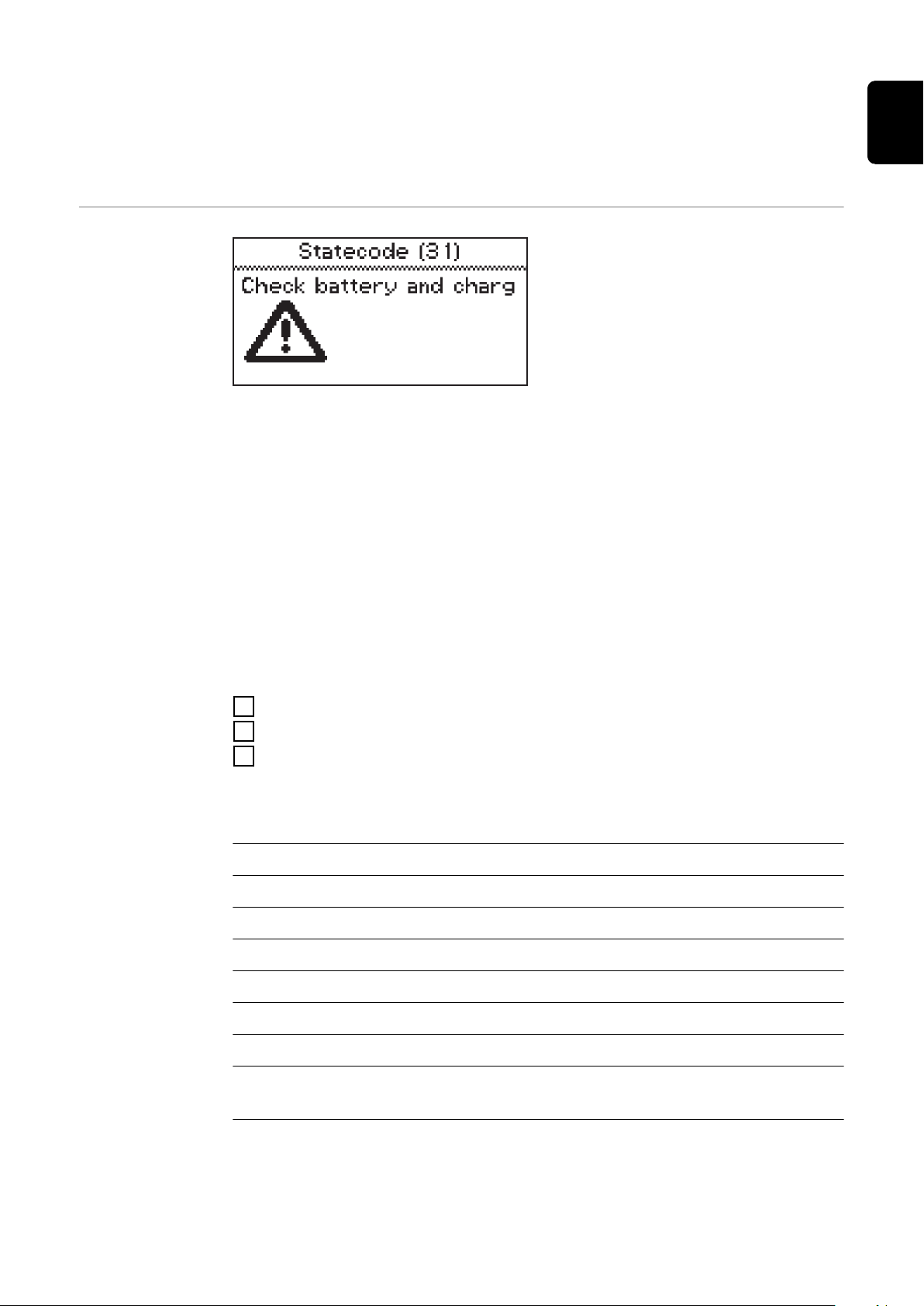
If a fault occurs during operation, specific status codes may be displayed. This
can be caused by the following:
Battery error
-
A battery with an unsuitable voltage has been connected.
-
The device has overheated.
-
A software or hardware error has occurred.
-
EN
Battery error:
If the battery reports an error state, the battery charger will display this error as
a battery error including the corresponding error number of the battery. The respective error explanation can be found in the Operating Instructions for the
battery.
If an error message appears on the display and the error cannot be rectified independently
Note down the displayed status code: e.g., "Statecode (31)".
1
Note the configuration of the device.
2
Contact your authorized Service Partner.
3
If the device is in an error state, a freely defined text can be displayed, which
can contain the contact details of the distributor, for example.
Status codes with an external cause
No. Cause/Remedy
(11) Check mains voltage
(12) Check grid (phase failure)
(13) External temperature sensor defective
(14) Electrolyte circulation defective (pressure switch does not switch)
(15) No control voltage detected
(16) External start/stop is not closed.
(17) Open circuit detection triggered several times during a charge (e.g.,: worn
charging contacts)
51
Page 52

Status codes in the event of a battery fault
No. Cause/Remedy
(22) Battery undervoltage
(23) Battery overvoltage
(24) Battery too hot (only with external temperature sensor)
(25) Battery undertemperature (only with external temperature sensor)
(26) Cell defect detected
(27) Battery not supported
(28) Battery heavily discharged - safety charge in progress
(29) Incorrect battery polarity
(30) Thermal runaway
Status codes in the event of a charging error
No. Cause/Remedy
(31) Time exceeded in the I1 phase
(32) Time exceeded in the U1 phase
(33) Battery overvoltage in the I2 phase
(34) Ah exceeded
(35) Time exceeded in the I2 phase
(36) Target voltage in the I2 phase not reached (only with format curve)
(37) RI charge error
(38) Set charging time cannot be reached
(39) Time exceeded during RI charge
Status codes in the event of a CAN error (battery)
No. Cause/Remedy
(51) Battery not responding
(52) Battery data cannot be queried
(53) Battery voltage not supported
(54) Communication error
52
(55) Battery error
(56) Battery does not switch on
(57) Message time limit exceeded
(58) Login failed
Page 53

Status codes in the event of a gateway error
No. Cause/Remedy
(101) CAN Connect setting is active and no CAN connection could be estab-
lished to the gateway for at least 2 minutes.
(102) Gateway has no connection to the back-end.
Status codes in the event of a TagID error
No. Cause/Remedy
(200) Set technology on the battery charger is not compatible with the connec-
ted battery.
(201) The nominal voltage of the battery is not supported by the battery char-
ger or is prevented by a battery charger setting
(202) The battery charger power is not high enough to charge the connected
battery
(203) CAN communication to TagID could not be established
(204) TagID data could not be read
(205) TagID update could not be performed
EN
(206) TagID temperature sensor is defective
(207) TagID voltage sensor is defective
(208) Battery master data of the TagID is invalid or not available
(209) Defective EEPROM memory
(210) Defective flash memory
(211) Invalid device signature
(212) TagID data could not be written
(213) The charger power is not sufficient to charge the battery in the desired
charging time
(214) Too much power dissipation on the DC path
(215) TagID level sensor is mounted in the wrong cell or is defective
(216) TagID SoftwareCrash
Status codes in the event of an error in the primary circuit
No. Cause/Remedy
(500) Temperature sensor module 1 (top) defective
(501) Temperature sensor module 2 (bottom) defective
(502) Temperature sensor PCB defective
(503) Primary overtemperature
(504) Fan blocked/defective
53
Page 54

(505) Over-/undervoltage in intermediate circuit
(506) Asymmetry in intermediate circuit
(507) Primary supply voltage out of tolerance
(508) Grid failure
(509) Incorrect device configuration
(510) Primary EEPROM faulty
(527) Phaseshifter overcurrent
(528) High charge relay switched off during load operation
(530) Communication problem
(532) Microcontroller error (e.g., division by 0)
(533) Reference voltage out of tolerance
(534) Startup problem
(535) PFC overcurrent
(536) Phaseshifter or PFC faulty
Status codes in the event of an error in the secondary circuit
No. Cause/Remedy
(520) Secondary temperature sensor defective
(521) Secondary overtemperature
(522) Output fuse defective
(523) Secondary supply voltage out of tolerance
(524) Secondary reference voltage out of tolerance
(525) Current offset
(526) Current offset out of tolerance
(527) Power module overcurrent (primary)
(529) No secondary communication
(530) No primary communication
(531) Secondary EEPROM defective
(532) Microcontroller error
(537) Voltage measurement faulty
54
(570) Secondary relay cannot be switched
(571) ADC/SPI problem
Page 55

Status codes in the event of an error in the control system
No. Cause/Remedy
(540) Configuration memory block missing/defective
(541) No secondary communication
(542) Secondary Init failed
(543) Program/memory error in the curve control
(544) Program/memory error in the curve control
(545) Primary Init failed
(546) Update failed
(547) Load/save settings failed
(548) Load/save curve settings failed
(549) Charge could not be continued after a grid failure
(550) Time not set
(551) Hardware change detected
(552) Configuration memory block invalid
(553) Primary update failed
EN
(554) Communication faulty
(555) Incorrect device software
(557) Interruption of the InterLock communication
(558) The second device, which is connected via the InterLock, has an error
(559) The second device, which is connected via the InterLock option, is incom-
patible with this device
55
Page 56
Options
Safety The housing has to be partially opened to connect the options.
WARNING!
Danger of electric shock.
This may result in serious injuries or death.
The housing must never be opened by anyone other than a service technician
▶
trained by the manufacturer.
Before working with the housing open, the device must be disconnected from
▶
the grid.
A suitable measuring device must be used to ensure that electrically charged
▶
components (e.g., capacitors) are completely discharged.
With the aid of a clearly legible, understandable warning sign, ensure that
▶
the device remains disconnected from the grid until all work has been completed.
WARNING!
Danger due to work that is not carried out properly.
This can result in severe personal injury and damage to property.
All work involved with connecting optional components must only be carried
▶
out by service technicians trained by the manufacturer.
If there are Installation Instructions or User Information for the optional
▶
component concerned, then all warning notices and instructions therein
must be obeyed.
For all options with electrical connections, a safety inspection must be car-
▶
ried out in accordance with the applicable national and international standards and guidelines after connection work has been carried out.
You can obtain more information about the safety inspection from the au-
▶
thorized service body.
The service body will provide the necessary documents upon request.
▶
Electrolyte circulation 3 kW
56
NOTE!
Danger due to the ingress of electrolyte from the battery or due to operation
without any back pressure.
This may result in damage to the air pump.
Always set up the charger at least 0.5 m (1 ft. 7.69 in.) above the battery to
▶
be charged.
Always use an undamaged connecting hose provided specifically for this pur-
▶
pose to connect the charger's compressed air outlet to the battery.
NOTE!
Danger due to non-observance of the permissible mains voltage tolerance.
This can cause malfunctions and damage.
For the electrolyte circulation option, a restricted mains voltage tolerance
▶
vis-à-vis the charger of 207 V to 250 V applies.
The electrolyte circulation option introduces air into the battery through capillary tubes that are provided specifically for this purpose. This allows intensive
Page 57
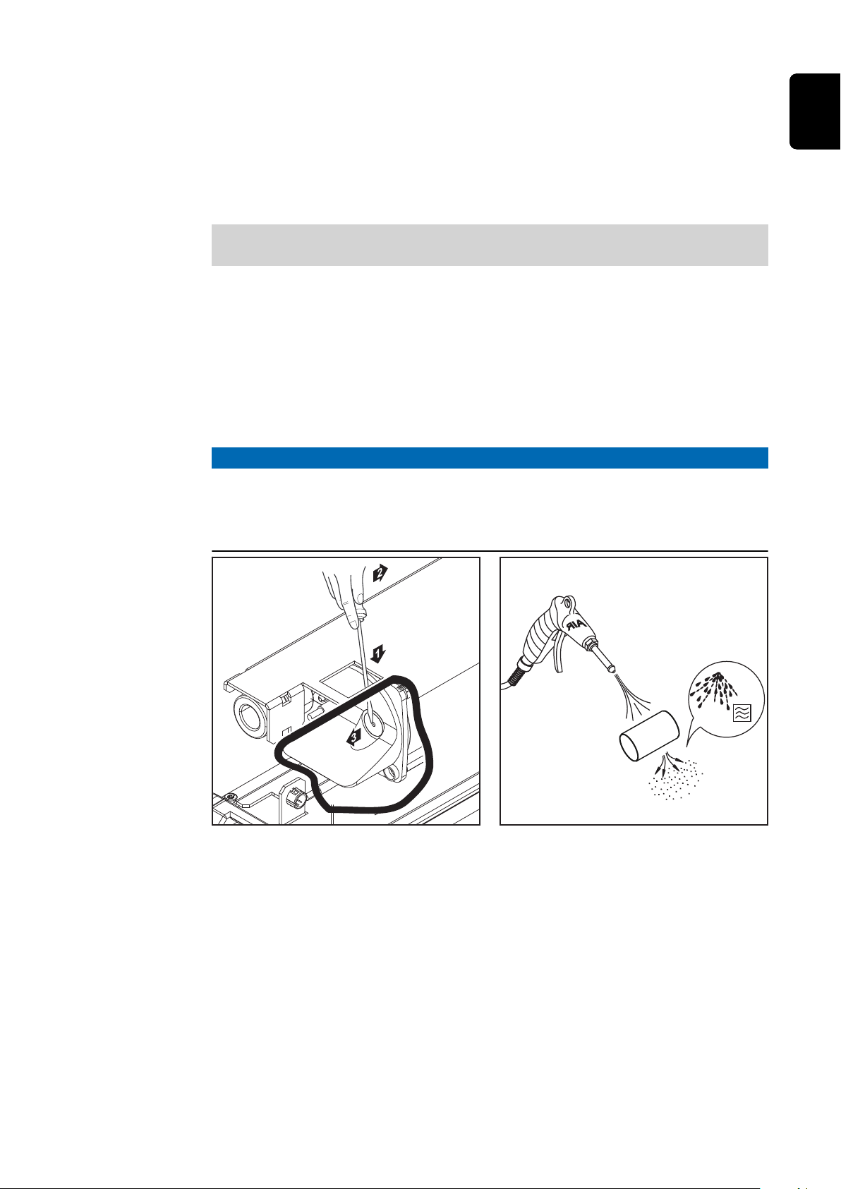
mixing of the electrolyte to take place. The benefit is the reduced heating of the
battery, and consequently longer battery-life, plus reduced water loss during
charging.
If a pump fault or leaks in the connection with the battery result in a fault being
detected, then the status code "Statecode 14" will appear on the display. One
way in which this fault can be indicated is by using an external indicator lamp to
show a common error.
Weight of the electrolyte circulation set:
Air-Puls + air hose kit
3 kW 2.5 kg (5.51 lb)
Electrolyte circulation air filter insert
The air filter insert for the integrated air pump should be cleaned once a year. In
dusty environments, the cleaning interval should be shortened accordingly. The
air filter insert must be removed for cleaning. Remove the air filter by levering it
out with a slotted screwdriver; then refit it as follows:
NOTE!
Danger from using the air filter with unsuitable chargers.
This can result in damage to property.
Only use the air filter with the chargers provided by the manufacturer for
▶
this purpose.
EN
57
Page 58
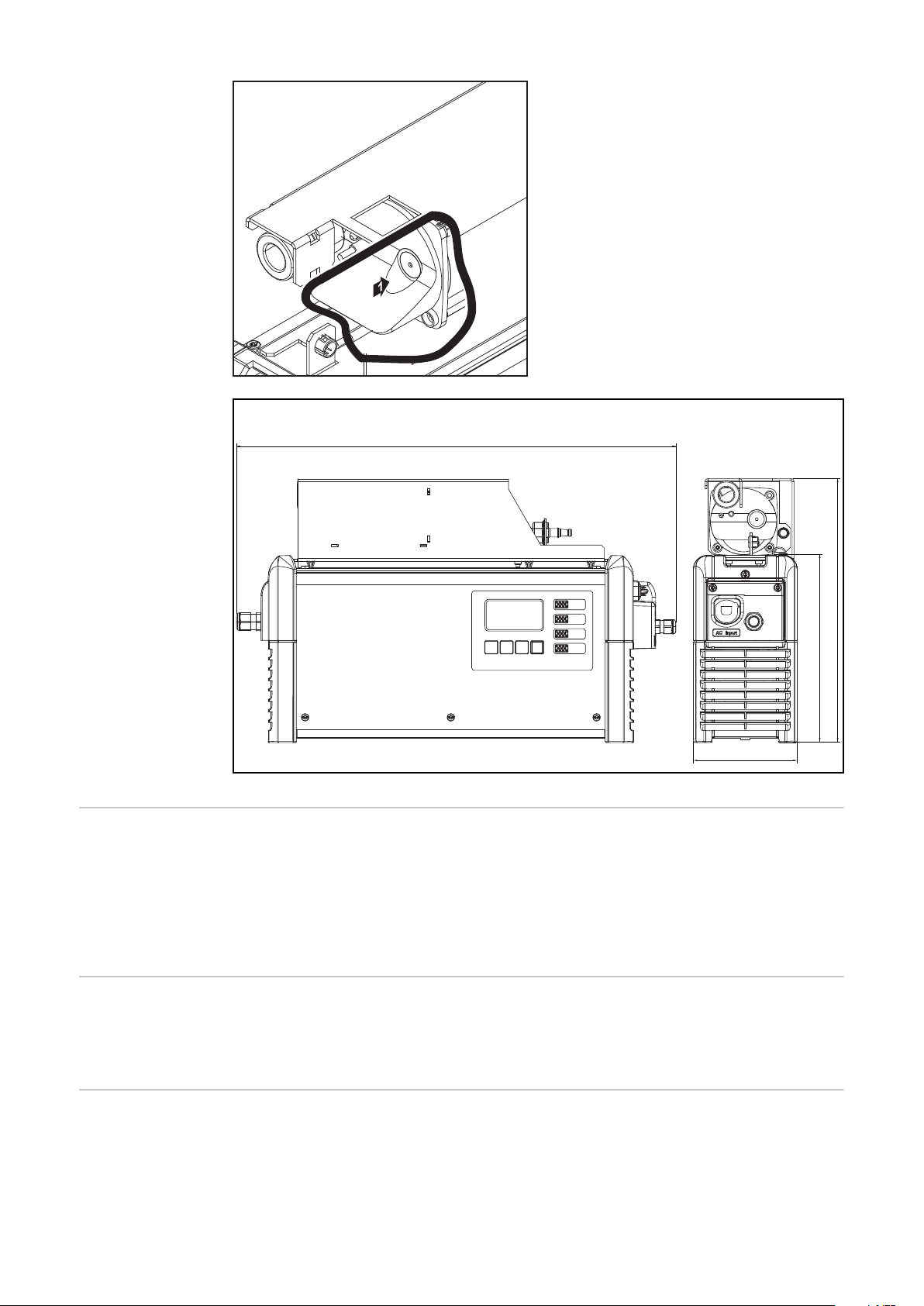
mm (in.)
464 (18.27)
110 (4.33)
198 (7.8)
278 (10.94)
External start/
stop
The external start/stop option prevents spark formation at the charging plug if it
is disconnected during charging. Special contacts inside the charging plug register a disconnection. These contacts are leading in comparison to the main
contacts. An immediate charging stop is triggered. There is therefore no wear on
the main contacts and the level of safety against oxyhydrogen ignition is increased.
Temperaturecontrolled charging
The temperature-controlled charging option always adjusts the charging voltage
according to the current temperature of the battery. This results in considerably
longer battery-life, especially where batteries are used in cold stores.
LED strip The LED strip acts as a status indicator and lights up in the same colours as the
display elements on the control panel. An LED strip including a diffuser is installed in the gap between the front wall and upper part of the housing.
58
Page 59
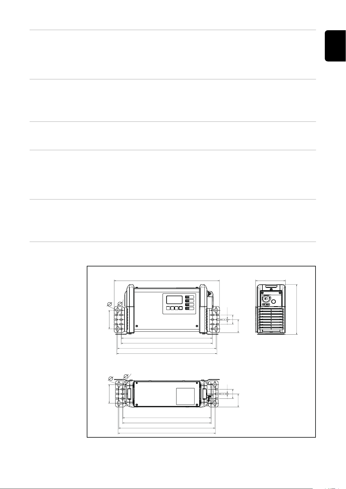
Air filter In dusty environments, the air filter prevents the inside of the device from be-
406 (15.98)
mm (in.)
2 kW (B1)
349 (13.74)
352 (13.86)
380 (14.96)
386 (15.2)
339 (15.98)
342 (13.74)
370 (13.86)
376 (14.96)
115 (4.53)
6,5 (.26)
38 (1.5)38 (1.5)
53.8
(2.12)
53.8
(2.12)
6,5 (.26)6,5 (.26)
76 (2.99)
205 (8.07)
76 (2.99)
14 (.55)
6,5 (.26)
14 (.55)
coming dirty. This avoids a possible reduction in power and other problems. Detailed information can be found in the corresponding User Information.
Cleaning interval as required (manufacturer's recommendation: monthly)
EN
Wall and floor
bracket
The robust wall and floor bracket with integrated cable holder ensures safe installation at the place of use. Detailed information and diagrams can be found in
under "Wall and floor bracket" in the "General information" chapter.
"Mobile" kit A carrying strap makes it easier to move the device.
Option box Using the option box, information on the state of charge of the connected bat-
tery can be obtained via an external circuit.
Error messages and additional features such as the Aquamatic control function,
external air pump and refill indicator can also be displayed.
Remote control
system
The remote control system allows full operation of the device from a distance of
up to 30 m (98 ft., 5.1 in.). This option includes a complete control panel in an
aluminum housing.
Mounting plate The mounting plate may be used as a space-saving floor or wall bracket.
59
Page 60
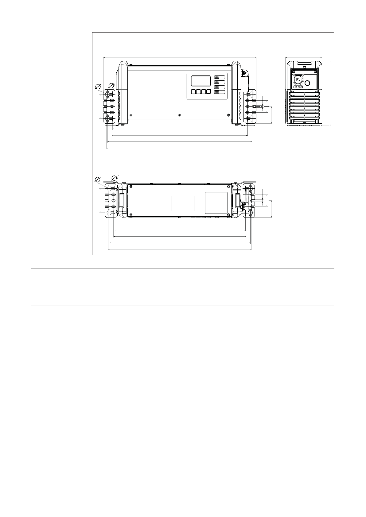
425 (16.73)
482 (18.98) 115 (4.53)
428 (16.85)
456 (17.95)
462 (18.19)
415 (16.34)
418 (16.46)
446 (17.56)
452 (17.80)
6,5 (.26)
38 (1.5)38 (1.5)
53.8
(2.12)
53.8
(2.12)
6,5 (.26)6,5 (.26)
76 (2.99)
205 (8.07)
76 (2.99)
14 (.55)
6,5 (.26)
14 (.55)
mm (in.)
3 kW (C1)
TagID The TagID is an electronic measurement and control system that exchanges bat-
tery data with the battery charger and optimizes charging.
TagID Link The TagID Link enables the exchange of relevant battery data between the TagID
and the battery charger.
60
Page 61

Technical data
EN
Selectiva 2 kW
Mains voltage
1)
~ 230 V, ± 15%
Grid frequency 50/60 Hz
Mains fuse protection
2)
max. 16 A
Minimum mains lead cross section 1.5 mm² (0.002325 in.²)
Protection class I (with ground conductor)
Max. permitted mains impedance Z
3)
PCC
max
on
None
Standby usage 4.9 W
EMC device class B
Dimensions L x W x H 341 x 110 x 198 mm
(13.43 x 4.33 x 7.8 in.)
Degree of contamination 3
Degree of protection
4)
IP21
Overvoltage category II
Operating temperature
5)
-20°C to +40°C
(-4°F to 104°F)
Storage temperature -25°C to +80°C
(-13°F to 176°F)
Relative humidity maximum 85%
Maximum altitude above sea level 2000 m (6561 ft.)
Mark of conformity according to rating plate
Product standard EN62477-1
1)
The device is approved for operation on neutral-earthed networks.
2)
The thermal stress of the circuit breaker must not exceed 30,000 A2s.
The leakage current to earth is less than 3.5 mA.
3)
Interface to a 230/400 V and 50 Hz public grid.
4)
For indoor use only, do not expose to rain or snow.
5)
A high ambient temperature may result in power degradation (derating).
Max.
Device-specific
data
Max. AC
current
Max. AC
power
Nominal
voltage
charging
current Weight
2040 2 kW 7.9 A 1540 W 24 V 40 A 5.8 kg
(12.79 lb)
2050 2 kW 9.9 A 1930 W 24 V 50 A 6.1 kg
(13.45 lb)
6)
2060 2 kW 12.0 A 2330 W 24 V 60 A 6.1 kg
(13.45 lb)
61
Page 62

Max.
Device-specific
data
Max. AC
current
Max. AC
power
Nominal
voltage
charging
current Weight
2070 2 kW 12.1 A 2350 W 24 V 70 A 6.1 kg
(13.45 lb)
4020 2 kW 7.9 A 1530 W 48 V 20 A 5.8 kg
(12.79 lb)
4035 2 kW 11.9 A 2330 W 48 V 35 A 5.8 kg
(12.79 lb)
6)
With standard mains and charging leads
6)
Selectiva 3 kW
Mains voltage
1)
~ 230 V, ± 15%
Grid frequency 50/60 Hz
Mains fuse protection
2)
max. 16 A
Minimum mains lead cross section 1.5 mm² (0.002325 in.²)
Protection class I (with ground conductor)
Max. permitted mains impedance Z
3)
PCC
max
on
None
Standby consumption
24 V devices
48 V devices
4.9 W
5.1 W
EMC device class B
Dimensions L x W x H 417 x 110 x 198 mm
(16.42 x 4.33 x 7.8 in.)
Degree of contamination 3
Degree of protection
4)
IP21
Overvoltage category II
Operating temperature
5)
-20°C to +40°C
(-4°F to 104°F)
62
Storage temperature -25°C to +80°C
(-13°F to 176°F)
Relative humidity maximum 85%
Maximum altitude above sea level 2000 m (6561 ft.)
Mark of conformity according to rating plate
Product standard EN62477-1
1)
The device is approved for operation on neutral-earthed networks.
2)
The thermal stress of the circuit breaker must not exceed 30,000 A2s.
The leakage current to earth is less than 3.5 mA.
3)
Interface to a 230/400 V and 50 Hz public grid.
4)
For indoor use only, do not expose to rain or snow.
Page 63
5)
A high ambient temperature may result in power degradation (derating).
Max.
Device-specific
data
Max. AC
current
Max. AC
power
Nominal
voltage
charging
current Weight
2080 3 kW 15.1 A 3040 W 24 V 80 A 8.2 kg
(18.08 lb)
2100 3 kW 15.3 A 3290 W 24 V 100 A 8.2 kg
(18.08 lb)
2120 3 kW 15.5 A 3340 W 24 V 120 A 8.7 kg
(19.18 lb)
4045 3 kW 15.0 A 3250 W 48 V 45 A 7.4 kg
(16.31 lb)
4060 3 kW 15.2 A 3280 W 48 V 60 A 7.4 kg
(16.31 lb)
6)
With standard mains and charging leads
EN
6)
63
Page 64
 Loading...