

Fronius Selectiva 1020E, Selectiva 1030E, Selectiva 2010E, Selectiva 2015E, Selectiva 2020E Operating Instruction [EN]
...Page 1
Operating
Instructions
Selectiva 1020E / 1030E / 2010E / 2015E /
2020E / 2032E / 2040E
Operating Instructions
EN
42,0426,0040,EN 011-18102022
Page 2

Page 3

Contents
Safety rules 4
General 4
Intended use 4
Environmental conditions 4
Mains connection 5
Dangers from mains current and charging current 5
Danger due to acid, gases and vapours 5
General information regarding the handling of batteries 6
Protecting yourself and others 6
Safety measures in normal operation 6
EMC device classifications 6
EMC measures 7
Data protection 7
Maintenance 7
Maintenance and repair 7
Warranty and liability 7
Safety inspection 7
Markings on the device 8
Disposal 8
Copyright 8
General information 9
Principle 9
Device concept 9
Warning notices on the device 9
Before commissioning 11
Safety 11
Proper use 11
Mains connection 11
Safety strategy - standard protection devices 12
Control elements and connections 13
General 13
Control panel 13
Plugging in options 13
Connections 14
Removing covers for connections and options 14
USB update option 14
Fitting the optional bracket and strain-relief device for the charging lead 15
Edge guard option 15
Wall bracket option 15
Preparations for security lock 16
Installation 17
Charging the battery 18
Starting charging 18
Finishing charging 19
Interrupting charging 19
Setup menu 20
General remarks 20
Accessing the Setup menu 20
Selecting the characteristic type 20
Troubleshooting 21
Safety 21
Protection devices 21
Charging errors 22
Technical data 23
Selectiva 1 kW 23
EN
3
Page 4

Safety rules
General The device has been manufactured in line with the state of the art and according
to recognized safety standards. If used incorrectly or misused, however, it can
cause:
Serious or fatal injury to the operator or third parties
-
Damage to the device and other material assets belonging to the operating
-
company
Inefficient operation of the device
-
All persons involved in commissioning, operating, maintaining and servicing the
device must:
Be suitably qualified
-
Read and follow these Operating Instructions carefully
-
The Operating Instructions must always be at hand wherever the device is being
used. In addition to the Operating Instructions, attention must also be paid to
any generally applicable and local regulations regarding accident prevention and
environmental protection.
All safety and danger notices on the device:
Must be kept in a legible state
-
Must not be damaged/marked
-
Must not be removed
-
Must not be covered, pasted, or painted over
-
For the location of the safety and danger notices on the device, refer to the section headed "General information" in the Operating Instructions for your device.
Before switching on the device, rectify any faults that could compromise safety.
This is for your personal safety!
Intended use The device is to be used exclusively for its intended purpose. Any use above and
beyond this purpose is deemed improper. The manufacturer is not liable for any
damage, or unexpected or incorrect results arising out of such misuse.
Proper use also includes:
Carefully reading and following all Operating Instructions, safety and danger
-
notices
Performing all stipulated inspection and servicing work
-
Following all instructions from the battery and vehicle manufacturers
-
Proper handling of the device is essential for it to function correctly. Never pull
on the cable when handling the device.
Environmental
conditions
Operation or storage of the device outside the stipulated area will be deemed as
not in accordance with the intended purpose. The manufacturer shall not be held
liable for any damage arising from such usage.
For detailed information on the permitted environmental conditions, please refer
to the "Technical data".
4
Page 5

Mains connection
Devices with a higher rating may affect the energy quality of the mains due to
their current consumption.
This may affect device types in terms of:
Connection restrictions, requirements regarding permitted mains impedance
-
*)
-
Requirements with regard to the minimum short-circuit power requirement
*)
at the interface with the public grid
see "Technical data"
In this case, the operating company or the person using the device should check
whether the device may be connected, possibly by discussing the matter with the
energy company where appropriate.
IMPORTANT! Ensure that the grid connection is earthed properly!
EN
*)
Dangers from
mains current
and charging
current
Danger due to
acid, gases and
vapours
Anyone working with battery chargers exposes themselves to numerous dangers,
e.g.:
Risk of electrocution from mains current and charging current.
-
Hazardous electromagnetic fields, which can risk the lives of those using car-
-
diac pacemakers.
An electric shock can be fatal. Every electric shock is potentially life threatening.
To avoid electric shocks while using the charger:
Do not touch any live parts inside or on the outside of the charger.
-
Under no circumstances touch the battery poles.
-
Do not short-circuit the charging cable or charging terminals.
-
All cables and leads must be secured, undamaged, insulated and adequately dimensioned. Loose connections, scorched, damaged or inadequately dimensioned
cables and leads must be immediately repaired by authorised personnel.
Batteries contain acid which is harmful to the eyes and skin. During charging,
gases and vapours are released that may be harmful to health and are highly explosive in certain circumstances.
Only use the charger in well-ventilated areas to prevent the accumulation of explosive gases. Battery rooms are not deemed to be hazardous areas provided that
a concentration of hydrogen of less than 4% can be guaranteed by the use of natural or forced ventilation.
Maintain a distance of at least 0.5 m (19.69 in.) between the battery and charger
during the charging procedure. Possible sources of ignition such as fire and naked flames must be kept away from the battery.
The battery connection (e.g. charging terminals) must not be disconnected for
any reason during charging.
Do not inhale any of the gases and vapours released under any circumstances Make sure the area is well ventilated.
To prevent short circuits, do not place any tools or conductive metals on the battery.
5
Page 6

Battery acid must not get into the eyes or onto the skin or clothes. Wear protective goggles and suitable protective clothing. Rinse any acid splashes thoroughly
with clean water and seek medical advice if necessary.
General information regarding
the handling of
batteries
Protecting yourself and others
Protect batteries from dirt and mechanical damage.
-
Store charged batteries in a cool place. Self discharge is kept to a minimum
-
at approx. +2 °C (35.6 °F).
Carry out a visual inspection at least once a week or as often as specified by
-
the battery manufacturer to ensure that the acid (electrolyte) level in the
battery is at the max. mark.
If any of the following occur, do not start the device (or stop immediately if
-
already in use) and have the battery checked by an authorised workshop:
uneven acid levels and/or high water consumption in individual cells
-
caused by a possible fault.
overheating of the battery above 55 °C (131 °F).
-
While the charger is in operation, keep all persons, especially children, out of the
working area. If, however, there are people in the vicinity,
warn them about all the dangers (hazardous acids and gases, danger from
-
mains and charging current, etc.),
provide suitable protective equipment.
-
Before leaving the work area, ensure that people or property cannot come to any
harm in your absence.
Safety measures
in normal operation
EMC device classifications
Chargers with a ground conductor must only be operated on a mains supply with
a ground conductor and a socket with a ground conductor contact. If the charger
is operated on a mains supply without a ground conductor or in a socket without
a ground conductor contact, this will be deemed gross negligence. The manufacturer shall not be held liable for any damage arising from such usage.
Only operate the charger in accordance with the degree of protection shown on
the rating plate.
Under no circumstances operate the charger if there is any evidence of damage.
Arrange for the mains cable to be checked regularly by a qualified electrician to
ensure the ground conductor is functioning properly.
Any safety devices and parts that are not functioning properly or are in imperfect
condition must be repaired by a qualified technician before switching on the
charger.
Never bypass or disable protection devices.
After installation, an accessible mains plug is required.
Devices with emission class A:
Are only designed for use in an industrial setting.
-
Can cause conducted and emitted interference in other areas.
-
6
Page 7

Devices with emission class B:
Satisfy the emissions criteria for residential and industrial areas. This also
-
applies to residential areas in which power is supplied from the public lowvoltage grid.
EMC device classification according to the rating plate or the technical data.
EMC measures In certain cases, even though a device complies with the standard limit values for
emissions, it may affect the application area for which it was designed (e.g. when
there is sensitive equipment at the same location, or if the site where the device
is installed is close to either radio or television receivers).
If this is the case, then the operating company is obliged to take appropriate action to rectify the situation.
Data protection The user is responsible for the safekeeping of any changes made to the factory
settings. The manufacturer accepts no liability for any deleted personal settings.
Maintenance Before switching on, always check the mains plug and cable as well as charger
leads and charging terminals for any signs of damage.
If the surface of the device housing is dirty, clean with a soft cloth and solventfree cleaning agent only.
EN
Maintenance and
repair
Warranty and liability
Safety inspection
Maintenance and repair work must only be carried out by authorised personnel.
Use only original spare and wearing parts (also applies to standard parts). It is
impossible to guarantee that bought-in parts are designed and manufactured to
meet the demands made on them, or that they satisfy safety requirements.
Modifications, installations or conversions are only permitted with the approval
of the manufacturer.
The warranty period for the charger is 2 years from the date of invoice.
However, the manufacturer will not accept any liability if the damage was caused
by one or more of the following:
Use of the charger "not in accordance with the intended purpose"
-
Improper installation and operation.
-
Operating the charger with faulty protection devices.
-
Non-compliance with the operating instructions.
-
Unauthorised modifications to the charger.
-
Catastrophes caused by the activities of third parties and force majeure.
-
The manufacturer recommends that a safety inspection of the device is performed at least once every 12 months.
The safety inspection may only be performed by an appropriately qualified electrician
After any changes have been made
-
After any additional parts are installed, or after any conversions
-
After repair, care and maintenance are carried out
-
At least every twelve months
-
7
Page 8

For safety inspections, follow the appropriate national and international standards and directives.
Further details on safety inspections can be obtained from your service centre.
They will provide you on request with any documents you may require.
Markings on the
device
Disposal Waste electrical and electronic equipment must be collected separately and re-
Copyright Copyright of these Operating Instructions remains with the manufacturer.
Devices with the CE marking satisfy the essential requirements of the applicable
guidelines.
Devices displaying the EAC mark of conformity satisfy the requirements of the
relevant standards in Russia, Belarus, Kazakhstan, Armenia and Kyrgyzstan.
cycled in an environmentally-friendly way, in accordance with the European Directive and national legislation. Used equipment must be returned to the distributor or disposed of via an approved local collection and disposal facility. Correct
disposal of used equipment promotes the sustainable recycling of material resources. Failing to dispose of used equipment correctly can lead to adverse
health and/or environmental impacts.
Packaging materials
Separate collection according to material. Check your local authority regulations.
Crush containers to reduce size.
Text and illustrations were accurate at the time of printing. Fronius reserves the
right to make changes. The contents of the Operating Instructions shall not
provide the basis for any claims whatsoever on the part of the purchaser. If you
have any suggestions for improvement, or can point out any mistakes that you
have found in the Operating Instructions, we will be most grateful for your comments.
8
Page 9
General information
Principle The main feature of the new Active In-
verter Technology is intelligent charging. This means that the charging behaviour adapts itself automatically to
the age and state of charge of the battery. This innovation extends the battery life and reduces the amount of
maintenance required, while at the
same time improving cost-effectiveness.
Active Inverter Technology is based on
an inverter with active rectification and
an intelligent safety cut-out. The charging current and voltage are held constant by a digital control that is not affected by any fluctuations in the mains
voltage.
EN
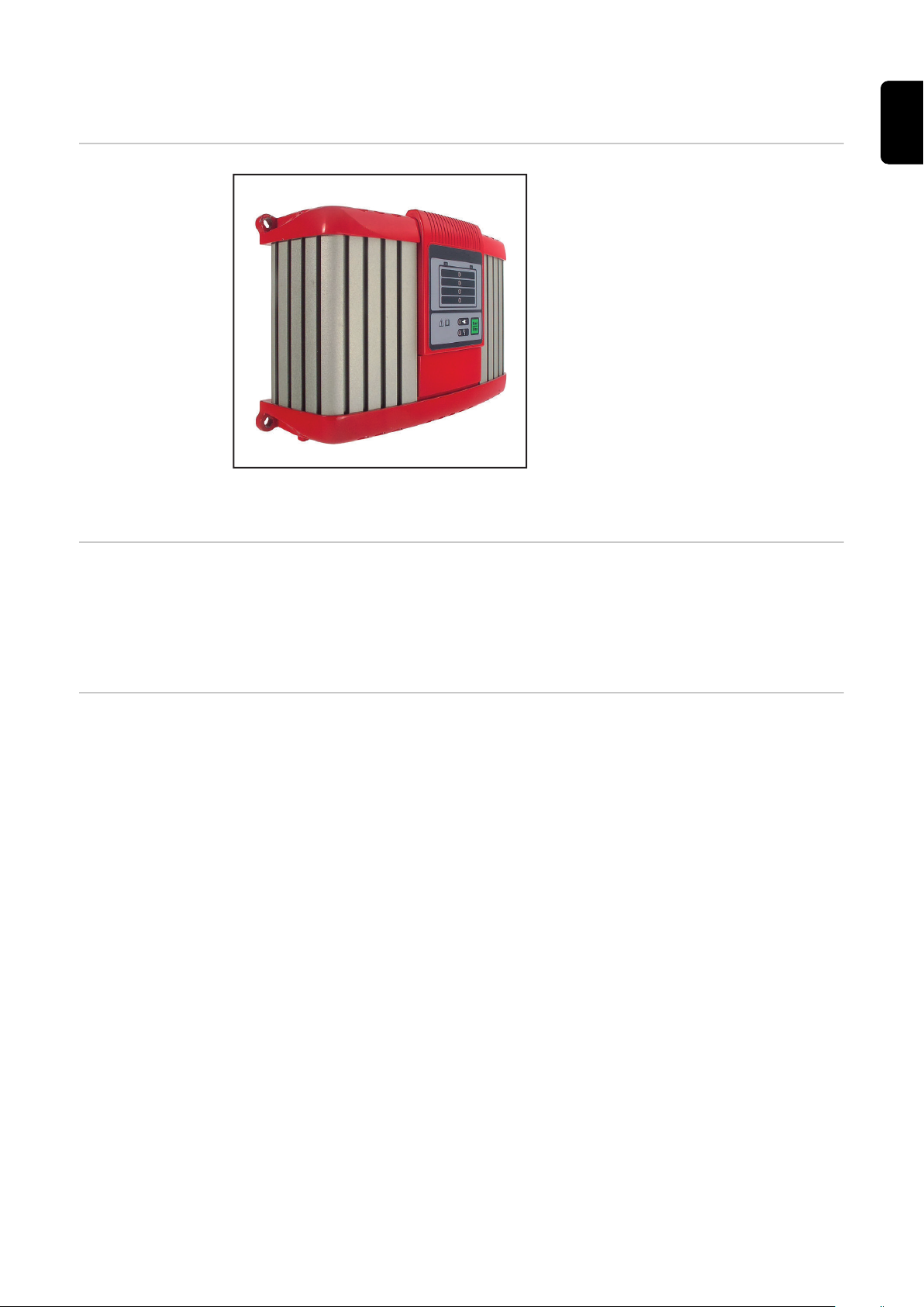
Device concept The compact design reduces space requirements and makes portable use con-
siderably easier. Add to this the fact that the active inverters can be used "onboard". In addition to its many existing features, the charger has a modular
design that makes it easy to upgrade; it is therefore ideally equipped for future
requirements. A wide range of options is available.
Warning notices
on the device
A number of safety symbols can be seen on the charger's rating plate. The safety
symbols must not be removed or painted over.
9
Page 10

Ladevorgang immer stoppen bevor das Ladekabel abgezogen wird!
Explosive Gase. Flammen und Funken vermeiden.
Während des Ladens für ausreichend Frischluft-Zufuhr sorgen!
Always stop charging before you disconnect the charging cable!
Explosive gases. Prevent flames and sparks.
Provide adequate ventilation during charge!
Toujours arrêter la charge avant de déconnecter le câble de charge!
Gaz explosifs. Éviter les flammes et les étincelles.
Prévoir une ventilation adaptée pendant la charge!
¡Detener siempre la carga antes de desconectar el cable de carga!
Gases explosivos. Evitar llamas y chipas.
¡Mantener una ventilación adecuada durante la carga!
Interrompere sempre la carica prima di scollegare il cavo di carica!
Gas esplosivi. Evitare fiamme libere e scintille.
Predisporre una ventilazione adeguata durante la carica!
WARNUNG - WARNING - ATTENTION
ADVERTENCIA - AVVISO
42,0409,0419
SN:
In:
Out.:
Art. Nr.:
~230V 50/60Hz;xxxW
DC xxV/xxA
A-4600 Wels
www.fronius.com
Active Inverter xxxxE
IP 40
Always stop charging before you disconnect the charging cable!
EMC Emission
Class A
xxxxxxxx
xxxxxxxx
4,010,xxx
Do not use the functions until you have read all the operating instructions.
Possible sources of ignition, such as fire, sparks and naked flames,
must be kept away from the battery.
Risk of explosion! Oxyhydrogen is generated in the battery during charging.
Battery acid is corrosive and MUST be kept away from eyes, skin and
clothes.
Ensure an adequate supply of fresh air during charging. Maintain a distance of at least 0.5 m (19.69 in.) between battery and charger during
the charging procedure.
Do not dispose of used chargers with domestic waste. Dispose of them
according to safety rules.
10
Page 11

Before commissioning
EN
Safety
Danger from incorrect operation.
This can result in severe personal injury and damage to property.
▶
▶
▶
▶
Proper use The charger is designed to charge the batteries listed below. Any use above and
beyond this purpose is deemed improper. The manufacturer shall not be liable
for any damage resulting from such use. Proper use also includes
-
-
Danger from charging dry batteries (primary cells) and non-rechargeable batteries.
This may result in serious injury and damage to property.
▶
WARNING!
Do not use the functions described here until you have fully read and understood the following documents:
Operating Instructions,
all the Operating Instructions for the system components, especially the
safety rules,
Battery and vehicle manufacturer's Operating Instructions and safety rules.
following all the instructions contained in the Operating Instructions,
regular checking of the mains and charging leads.
WARNING!
Only charge the battery types listed below.
Mains connection
The following battery types may be charged:
Wet batteries:
-
Sealed batteries with a liquid electrolyte (recognisable by the vent plugs) and
low-maintenance/maintenance-free wet batteries (MF).
Absorbent Glass Mat (AGM) batteries:
-
Sealed batteries (VRLA) with immobilised electrolyte (sealant).
Gel batteries:
-
Sealed batteries (VRLA) with immobilised electrolyte (gel).
The rating plate, which is located on the housing, contains information about the
permitted mains voltage. The device is designed for this mains voltage only. The
required fuse protection for the mains lead can be found in the accompanying
characteristic data sheet. If there is no mains cable or mains plug on your version
of the appliance, fit one that conforms to national standards.
NOTE!
Danger due to insufficiently dimensioned electrical installations.
This may result in serious injury and damage to property.
The mains lead and its fuse must be dimensioned to suit the local power sup-
▶
ply. The technical data shown on the rating plate applies.
11
Page 12

Safety strategy standard protection devices
The new chargers are not just characterised by purely functional features. In
terms of safety, the active inverters are also equipped to the highest standards.
The following safety features come as standard:
Reverse polarity protection prevents the battery or charger from being dam-
-
aged or destroyed.
Short-circuit protection provides effective protection for the charger. The
-
fuse does not need to be replaced in the event of a short circuit.
A charging time monitor provides effective protection against overcharging
-
and destruction of the battery.
Overtemperature protection through derating (charging current reduced if
-
the temperature rises above the permitted level).
12
Page 13

Control elements and connections
(1)
(2)
(3)
(4)
(7)
(5)
(6)
(8)
General Please note:
as a result of firmware updates, you may find that there are functions available
on your device that are not described in these Operating Instructions, or vice
versa.
Certain illustrations may also differ slightly from the actual controls on your
device, but these controls function in exactly the same way.
WARNING!
Danger from incorrect operation.
This can result in severe personal injury and damage to property.
Do not use the functions described here until you have read and completely
▶
understood these operating instructions.
Do not use the functions described here until you have fully read and under-
▶
stood all of the Operating Instructions for the system components, in particular the safety rules.
EN
Control panel The control panel (LED version) is explained below.
(1) State of charge indicator 25%
(2) State of charge indicator 50%
(3) State of charge indicator 75%
(4) State of charge indicator 100%
(5) Ready indicator
(6) -
(7) Start/Stop and setup button
(8) Error indicator
for interrupting and restart-
-
ing charging.
for selecting the character-
-
istic type (press and hold
for 10 s).
Plugging in options
NOTE!
Danger from connecting options and accessories while the mains plug is
plugged in.
This can result in damage to the device and accessories.
Only connect options and system add-ons when the mains plug is unplugged
▶
and the charging leads are disconnected from the battery.
13
Page 14

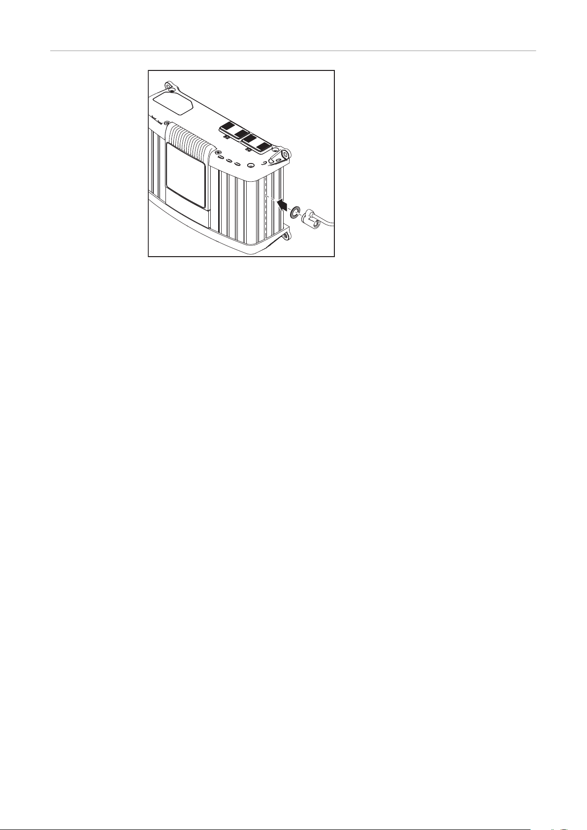
Connections
(1)
(3) (4)
(2)
(6)
(7)
(5)
(1)
(2)
No. Function
(1) AC input - mains socket
(2) Mains cable safety bow
for fitting the mains cable.
(3) Connection P2 - I/O port
for options on the I/O port.
(4) Connection P1 - charger lead
socket
also for external stop and temperature-controlled charging
options.
Bottom of housing
No. Function
(5) Removable display
(6) Connection P3 - Visual Port
for connecting the internal display.
Removing covers
for connections
and options
Top of housing
(7) Connection P4 - Multi Port
for connecting the following options:
Status lamp.
-
Software update via USB
-
port.
If necessary, use a screwdriver to remove:
Cover (1) for connection P4 - Multi
-
Port.
Cover (2) for connection P2 - I/O
-
port.
Leave covers (1) and (2) in place on unused P2 and P4 connections.
USB update option
14
The USB update option allows the charger to be updated directly via the USB interface.
Page 15

Fitting the op-
1
2
3
4
(1) (2) (3) (4)
1
2
2
1
1
"click"
"click"
~ 120 mm
~ 4.72 inch
130 mm
5.12 inch
tional bracket
and strain-relief
device for the
charging lead
Please note:
the torque for all screws is 2.5 Nm
(1.84 ft. lb.).
To fit the bracket:
Undo the screws (1).
-
Fit bracket (2) using the previously
-
removed screws.
To fit the strain-relief device:
Undo screw (3).
-
Fit charging lead strain-relief
-
device (4) using the previously undone screw.
EN
Edge guard option
Wall bracket option
The edge guard removal process is the
reverse of the fitting process.
The bracket cannot be fitted if the
edge guard is already in place.
Different wall plugs and screws will be required depending on the supporting surface. Wall plugs and screws are therefore not included in the scope of supply.
The installer is responsible for selecting the right wall plugs and screws.
15
Page 16
Preparations for
security lock
The security lock is not contained in
the scope of supply.
A security lock can only be attached
to the groove on the housing as
-
shown.
to the groove on the housing that
-
is exactly opposite.
using spacer M8 DIN 125 or DIN
-
134, located as shown.
16
Page 17

Installation If installing the charger on a firm base, use the drilling template enclosed in the
247 (9.72)
88 (3.46)
126 (4.97)
140 (5.51)
60 +20*
(2.36 + .79*)
70 + 20*
(2.76 + .79)
11 + 5*
(.43 + .2*)
162 (6.38)
233 (9.17)
6,5 (.26)
100 (3.94)
15,5 (.61)
168
(6.61)
270 (10.63)
packaging.
If the charger is installed in a switch cabinet (or a similar sealed area), then
forced-air ventilation must be provided to ensure adequate heat dissipation.
There must be a clearance of 10 cm (3.94 in.) all around the charger.
The space requirement measurements in mm (inches) illustrated below are given
to ensure that there is easy access to the plug connections:
EN
*Space for installation/removal
Space requirements with edge protector (*Space for installation/removal)
17
Page 18

Charging the battery
25 % 50 % 75 % 100 %
Starting charging
CAUTION!
Risk of damage if attempting to charge a faulty battery or using the incorrect
charging voltage.
This can result in damage to property.
Before beginning charging, ensure that the battery to be charged is fully
▶
functional and the charging voltage of the device matches the battery
voltage.
Connect the mains cable to the charger and plug into the mains.
1
Charger is on standby. Ready indicator lit.
2
Select characteristic type according to the battery to be charged.
3
Please note:
Information on which characteristic type to select can be found in the "Setup
menu" section or the enclosed characteristic data sheet.
WARNING!
Danger due to incorrectly connected charging plugs.
This may result in serious injury and damage to property.
Connect charging leads to the correct poles and ensure proper electrical
▶
connection to the battery poles.
If using the vehicle power supply, switch off the ignition and all other devices
4
consuming power.
Connect the charging lead (red) to the positive pole (+) on the battery.
5
Connect the charging lead (black) to the negative pole (-) on the battery.
6
Charging begins automatically after approx. 2 seconds.
7
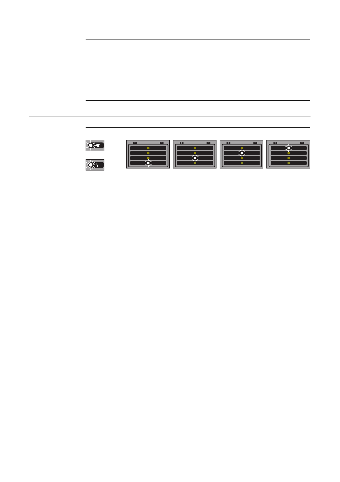
A set of four LEDs shows the battery's state of charge.
8
Conservation charging: once the battery is fully charged, the charger auto-
9
matically switches to conservation charging to prevent self discharge of the
battery. The battery can remain connected to the charger for any length of
time.
18
Page 19

Finishing charging
WARNING!
Danger due to ignition of oxyhydrogen caused by sparks generated when the
charging plug is disconnected prematurely.
This can result in serious injury and damage to property.
Before disconnecting the charging plug, press the Stop/Start button to finish
▶
charging.
Press the Stop/Start button to complete charging.
1
Disconnect the charging lead (black) from the negative pole (-) on the bat-
2
tery.
Disconnect the charging lead (red) from the positive pole (+) on the battery.
3
When the charging contacts are open, the automatic open circuit voltage detection ensures that the charging contacts are de-energised.
EN
Interrupting
charging
NOTE!
Danger from disconnecting or unplugging the charging lead during charging.
This can result in damage to the connection sockets and connecting plug.
Do not disconnect or unplug the charging lead while charging.
▶
Press the Stop/Start button while charging.
1
The process is interrupted.
-
Ready indicator flashes.
-
Press the Stop/Start button again to continue charging.
2
19
Page 20
Setup menu
General remarks Select the characteristic type in the Setup menu depending on either the battery
to be charged or the requirement as specified in the accompanying characteristic
data sheet.
Accessing the
Setup menu
Selecting the
characteristic
type
Please note:
Do not connect the charging lead to the battery.
A characteristic type cannot be selected when the charging plug is connected.
Connect the mains cable to the charger and plug into the mains.
1
Charger is on standby - ready indicator is lit.
2
Press and hold the Start/Stop button for approx. 10 seconds to call up the
3
Setup menu.
Ready indicator goes out. The charger is in Setup mode. The display also
4
shows the selected characteristic type.
Press the Start/Stop button to select the characteristic type according to
1
the enclosed characteristic data sheet.
If there is no further selection within 10 seconds, the selected characteristic
2
type is saved.
Please note:
Do not connect a battery during these 10 seconds.
Continue as described in the section "Charging the battery".
20
Ready indicator lights up. Once the new characteristic type has been selec-
3
ted, the charger is automatically ready for the next charging sequence.
Page 21

Troubleshooting
EN
Safety
WARNING!
Risk of electric shock.
This can result in serious injuries or death.
Before opening the device:
▶
Unplug the device from the mains.
▶
Disconnect battery.
▶
Put up an easy-to-understand warning sign to stop anybody inadvertently
▶
switching it back on again.
Using a suitable measuring instrument, ensure that electrically charged com-
▶
ponents (e.g. capacitors) have been discharged.
WARNING!
Danger from an inadequate ground conductor connection.
This can result in severe personal injury or damage to property.
The housing screws provide a suitable PE conductor connection for earthing
▶
the housing and must NOT be replaced by any other screws that do not
provide a reliable PE conductor connection.
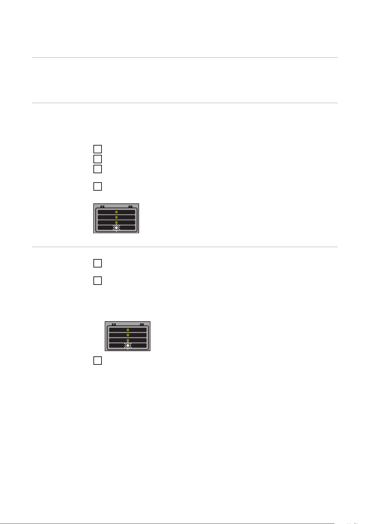
Protection
devices
Ready indicator flashing, error indicator flashing:
Cause: Mains fault - mains voltage outside the tolerance range.
Remedy: Check mains conditions.
Ready indicator lit, error indicator flashing:
Cause: Short circuit on the charging plug or charger lead. Short circuit
detection active.
Remedy: Check charger leads, contacts and battery poles.
Cause: Battery overvoltage or undervoltage.
Remedy: Select correct charging characteristic/function, or set correct
battery voltage.
Ready indicator lit, error indicator lit:
Cause: Polarity reversal of charger leads. Reverse polarity protection
has tripped.
Remedy: Connect battery poles correctly.
21
Page 22
Charger switches off during charging:
Cause: Ambient temperature too high. Overtemperature protection act-
ive.
Remedy: Allow device to cool down. Charging will recommence automat-
ically once the device has cooled sufficiently. If not, have it
checked by a workshop.
Charging errors
Ready indicator lit, error indicator flashing, SOC indicator 1/2/3/4 flashing:
Cause: Timeout in the corresponding charging phase or battery capa-
city too high.
Remedy: Select correct characteristic type according to the enclosed
characteristic data sheet and charge again.
Cause: Battery faulty (cell short circuit, heavy sulphation).
Remedy: Check battery and replace if necessary.
Cause: Optional external temperature sensor has tripped due to over-
or undertemperature.
Remedy: Allow battery to cool, or charge battery in a more suitable area.
22
Page 23

Technical data
EN
Selectiva 1 kW
Mains voltage (+/- 15%) ~230 V AV
Mains frequency 50/60 Hz
Mains fuse max. 16 A
Battery backfeed current < 1 mA
Efficiency max. 96 %
Standby consumption max. 1.7 W
Safety class I
Max. permitted grid impedance Z
PCC
EMC emission class A
Dimensions L x W x H 247 x 162 x 88 mm
Weight (without cables)
1020E | 1030E | 2010E | 2015E
2020E | 2032E | 2040E
Cooling
1020E | 1030E | 2010E | 2015E
2020E | 2032E | 2040E
max
on
None
(9.72 x 6.38 x 3.46 in)
2.1 kg (4.63 lb.)
2.2 kg (4.85 lb.)
Convection
Convection and fan
Cooling Convection
Operating temperature
(>30 °C / >86 °F derating)
Storage temperature -40 °C to +85 °C
Protection class IP 40
Mark of conformity According to rating plate
Housing A1
Product standard IEC 60068-2-27 (shock)
Device-specific data
-20 °C to +40 °C
(-4 °F to 104 °F)
(-40 °F to 185 °F)
IEC 60068-2-29 (bump)
IEC 60068-2-64 (vibration)
EN 60335-1
EN 60335-2-29
EN 61000-3-2
EN 61000-6-2 (EN 61000-4-2,
EN 61000-4-3, EN 61000-4-4,
EN 61000-4-5, EN 61000-4-6,
EN 61000-4-11)
EN 61000-6-4 (Class A)
Device Grid cur-
rent max.
1020E 2.3 A 315 W 12 V DC /
Effective
power
max.
Nominal
output
voltage
6 cells
Output
voltage
range
2 V to
16.8 V DC
Output
current
20 A at
14.4 V DC
23
Page 24

Device-specific data
Device Grid cur-
rent max.
1030E 2.9 A 420 W 12 V DC /
2010E 2.3 A 340 W 24 V DC /
2015E 2.7 A 410 W 24 V DC /
2020E 4 A 650 W 24 V DC /
2032E 7.6 A 1030 W 24 V DC /
2040E 7.7 A 1120 W 24 V DC /
Effective
power
max.
Nominal
output
voltage
6 cells
12 cells
12 cells
12 cells
12 cells
12 cells
Output
voltage
range
2 V to
16.8 V DC
2 V to
33.6 V DC
2 V to
33.6 V DC
2 V to
33.6 V DC
2 V to
33.6 V DC
2 V to
33.6 V DC
Output
current
30 A at
13.5 V DC
10 A at
28.8 V DC
15 A at
24 V DC
20 A at
28.8 V DC
32 A at
28.8 V DC
35 A at
28.8 V DC
24
Page 25

EN
25
Page 26

26
Page 27

EN
27
Page 28

 Loading...