


/ Perfect Charging / Perfect Welding / Solar Energy
Virtual Welding
VR-Brille in das Kopf-Halteband
integrieren
Integrating 3D glasses into the
headband
Installationsanleitung
DEEN
Training
Installations instructions
Training
42,0410,2159 003-14062018

2

Inhaltsverzeichnis
Allgemeines ............................................................................................................................................... 5
Sicherheit.............................................................................................................................................. 5
Übersicht............................................................................................................................................... 5
Lieferumfang......................................................................................................................................... 5
VR-Brille in das Kopf-Halteband integrieren .............................................................................................. 6
Vordere Kabelführung montieren.......................................................................................................... 6
VR-Brille montieren............................................................................................................................... 7
Hintere Kabelführung montieren........................................................................................................... 8
Kabel mit Schutzschlauch umwickeln................................................................................................... 9
DE
3

4

Allgemeines
DE
Sicherheit
Übersicht Das vorliegende Dokument erklärt die Montage einer VR-Brille und ihres Zubehörs an dem
mitgelieferten Kopf-Halteband.
Lieferumfang
(1)
(1)
VORSICHT! Eine fehlerhafte Montage kann Personen- und Sachschäden verursachen.
Alle in diesem Dokument beschriebenen Arbeiten und Funktionen dürfen nur von
geschultem Fachpersonal ausgeführt werden, wenn folgende Dokumente vollständig gelesen und verstanden wurden:
- dieses Dokument
- sämtliche Dokumente der Systemkomponenten, insbesondere Sicherheitsvorschriften
(1) Schrauben
(2) Halterung
(3) Kabelbinder
(4) Schraubendreher
(5) Kopf-Halteband
(6) Schutzschlauch 3,5 m
(2) (4) (5)(3)
(2) (4) (5)(3)
(6)
5
VR-Brille in das Kopf-Halteband integrieren
Vordere Kabelführung montieren
(1)
(3)
(2)
(2)
Seitliche Kunststoffmutter (1) samt
1
Kunststoffscheibe entfernen
Kabelführung (2) abnehmen
2
(2)
1
2
Mittels beiliegendem Schraubendreher
3
die 4 Schrauben (3) der Kabelführung
(2) entfernen
Kabelführung (2) auseinander nehmen
4
und die beiden Hälften ablegen
Die Kabel für den Kopfsensor und die
5
VR-Brille in die Kabelführung (2) einlegen
Folgende Entfernungen der Kabelfüh-
6
rung herstellen:
- von der VR-Brille:
ca. 10 cm (3.94 in.)
- vom Kopfsensor:
ca. 17 cm (6.69 in.)
(1)
Mittels der zuvor entfernten 4 Schrau-
7
ben (3) die Kabelführung (2) zusammenfügen
6
4x
(3)
(2)
Kabelführung (2) auf das Kopf-Halte-
8
band aufschieben
Seitliche Kunststoffmutter (1) samt
9
7
8
(2)
Kunststoffscheibe anschrauben
6

VR-Brille montieren
(1)
1
Kopf-Halteband hinter der VR-Brillen-
DE
Halterung (1) für den Kopfsensor am
halterung ansetzen
1
2
2
Halterung (1) mit 2 mitgelieferten
2
Schrauben (2) montieren
(2)
Kopfsensor (3) an der Halterung anset-
2x
4
(4)
3
(3)
(4)
3
zen
Kopfsensor (3) mit jeweils 2 Schrau-
4
ben (4) und Muttern (5) montieren
- um Beschädigungen zu vermei-
4
(5)
2x
den, die Schrauben (4) und Muttern (5) nicht zu stark
festschrauben
(6)
(7)
(8)
9
7
10
5
11
(7)
6
6
8
10
(9)
4 Schrauben (6) an der Brillenhalterung lockern
5
2 Fixierschrauben (7) für den Bolzen (8) entfernen
6
Bolzen (8) entfernen
7
VR-Brille (9) auf die Brillenhalterung stecken
8
Bolzen (8) durchführen
9
2 Fixierschrauben (7) für den Bolzen (8) festschrauben
10
4 Schrauben (6) an der Brillenhalterung festschrauben
11
- um eine Justierbarkeit der VR-Brille zu gewährleisten, die 4 Schrauben (6) nicht
zu stark festschrauben
(9)
7

Hintere Kabelführung montieren
(4)
(1)
(3)
Die hintere Kabelführung befindet sich hinter dem Halteband-Einstellknopf und ist nur
1
(1)
1
2
2
(3)
3
4
(2)
für das Kabel der VR-Brille bestimmt.
Druckknopf (1) der Lederummantlung
1
öffnen
Kabelführung (2) durch Lösen der bei-
(2)
2
den Schrauben (3) entfernen
Die übrigen beiden Schrauben (4) der
3
Kabelführung (2) entfernen
Kabelführung (2) auseinander nehmen
4
und die beiden Hälften ablegen
(4)
3
(2)
6
(4) (4)
8
(1)
Das Kabel für die VR-Brille in die Ka-
5
belführung (2) einlegen
Einen Abstand der hinteren Kabelfüh-
6
rung zur vorderen Kabelführung von
6
5
ca. 17 cm (6.69 in.) einstellen
Mittels der zuvor entfernten beiden
7
Schrauben (4) die Kabelführung (2) zusammenfügen
(3)(1)
Kabelführung (2) mit den beiden
8
Schrauben (3) befestigen
Druckknopf (1) an der Lederummant-
9
lung schließen
7
(2)
7
8
(3)
Kabel mittels Kabelbindern (5) befesti-
(5)
10
gen
- um eine Beschädigung der empfindlichen Datenkabel für die VR-
9
Brille zu vermeiden, die Kabelbinder nicht zu stark festziehen
9
(5)
8

Kabel mit Schutzschlauch umwickeln
Kabelbinder zur Kabelführung ver-
1
schieben
Beide Kabel von der Kabelführung weg
2
DE
auf ca. 1,8 m Länge mit dem Schutzschlauch umwickeln
1
2
1,8 m
3
VORSICHT! Verletzungsgefahr
durch losen Schutzschlauch!
Schutzschlauch an den Enden fixieren.
Schutzschlauch nach der Kabelfüh-
3
rung mit Klebeband fixieren
Schutzschlauch am Ende mit Klebe-
4
4
band fixieren
Kabel mit Schutzschlauch umwickelt
9

10

Contents
General ...................................................................................................................................................... 13
Safety.................................................................................................................................................... 13
Overview............................................................................................................................................... 13
Scope of supply .................................................................................................................................... 13
Integrating 3D glasses into the headband ................................................................................................. 14
Assembling the front cable guide.......................................................................................................... 14
Fitting the VR glasses........................................................................................................................... 15
Assembling the rear cable guide........................................................................................................... 16
Wrapping cable with protective hose .................................................................................................... 17
EN
11

12

General
Safety
Overview This document describes how VR glasses and accessories should be fitted to the head-
band provided.
Scope of supply
(1)
(1)
(2) (4) (5)(3)
(2) (4) (5)(3)
CAUTION! Incorrect installation can cause injury and damage.
All work and functions described in this document may only be carried out by
trained and qualified personnel after they have fully read and understood the following documents:
- this document
- all documents relating to the system components, especially the safety rules
(1) Screws
(2) Holder
(3) Cable ties
(4) Screwdriver
(5) Headband
(6) Protective hose 3.5 m
EN
(6)
13

Integrating 3D glasses into the headband
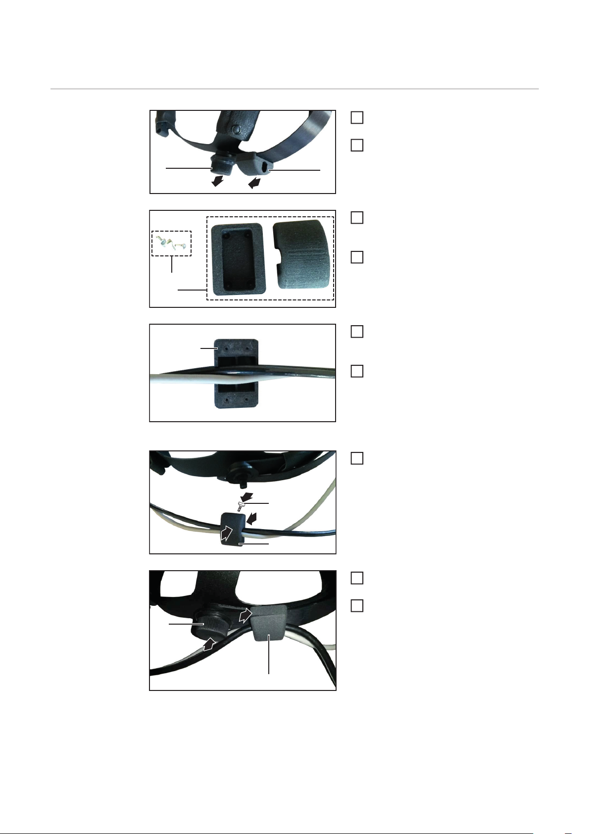
Assembling the
front cable guide
(1)
(3)
(2)
(2)
Remove the plastic nut (1) on the side
1
including the washer
Remove the cable guide (2)
2
(2)
1
2
Use the screwdriver provided to remo-
3
ve the four screws (3) on the cable guide (2)
Pull the cable guide (2) apart and lay
4
down the two halves
Insert the cable for the head sensor
5
and the VR glasses into the cable guide (2)
Adjust the following distances of the
6
cable guide:
- from the VR glasses:
approximately 10 cm (3.94 in.)
- from the headsensor:
approximately 17 cm (6.69 in.)
(1)
Use the four screws (3) you removed
7
earlier to reassemble the cable guide
(2)
6
4x
(3)
(2)
Push the cable guide (2) onto the
8
headband
Insert the plastic nut (1) on the side in-
9
7
8
(2)
cluding the washer
14

Fitting the VR
glasses
Position the holder (1) for the head
(1)
1
sensor on the headband behind the VR
glasses holder
1
2
2
Fit the holder (1) using the two screws
2
provided (2)
EN
(2)
Position the head sensor (3) on the
2x
4
(4)
3
(3)
(4)
3
holder
Fit the head sensor (3) using two
4
screws (4) and two nuts (5)
- in order to avoid damage, do not
4
(5)
2x
tighten the screws (4) and nuts (5)
too much
(6)
(7)
(8)
9
7
10
5
11
6
6
8
10
(9)
Loosen the four screws (6) on the glasses holder
5
Remove the two fixing screws (7) for the bolt (8)
6
Remove the bolt (8)
7
Insert the VR glasses (9) into the glasses holder
8
Insert the bolt (8)
9
Tighten the two fixing screws (7) for the bolt (8)
10
Tighten the four screws (6) on the glasses holder
11
- in order to guarantee the adjustability of the VR glasses, do not tighten the 4
screws (6) too much
(7)
(9)
15

Assembling the
rear cable guide
(4)
(1)
(3)
The rear cable guide is located behind the
headband adjustment knob and is only in-
1
(1)
1
2
2
(3)
3
4
(2)
tended for the VR glasses cable.
Open the fastener (1) on the leather
1
cover
Remove the cable guide (2) by loo-
(2)
2
sening the two screws (3)
Remove the remaining two screws (4)
3
on the cable guide (2)
Pull the cable guide (2) apart and lay
4
down the two halves
(4)
3
(2)
6
(4) (4)
8
(1)
Insert the cable for the VR glasses into
5
the cable guide (2)
Adjust a distance from the rear cable
6
guide to the front cable guide of appro-
6
5
ximately 17 cm (6.69 in.)
Use the two screws (4) you removed
7
earlier to reassemble the cable guide
(2)
(3)(1)
Attach the cable guide (2) using the
8
two screws (3)
Close the fastener (1) on the leather
9
cover
7
(2)
7
16
8
(3)
Secure the cables using the cable ties
(5)
10
(5)
- in order to avoid damage to the
sensitive data cables of the VR
9
glasses, do not tighten the cable
ties too much
9
(5)

Wrapping cable
with protective
hose
Push the cable tie to the cable guide
1
Starting from the cable guide, wrap
2
both cables with the protective hose for
a length of approx. 1.8 m
1
2
EN
1,8 m
3
CAUTION! Risk of injury from
loose protective hose!
Secure protective hose at the
ends.
Use adhesive tape to fix the protective
3
hose in place after the cable guide
Use adhesive tape to fix the protective
4
4
hose in place at the end
Cable wrapped with protective hose
17

18

EN
19

FRONIUS INTERNATIONAL GMBH
Froniusplatz 1, A-4600 Wels, Austria
Tel: +43 (0)7242 241-0, Fax: +43 (0)7242 241-3940
E-Mail: sales@fronius.com
www.fronius.com
www.fronius.com/addresses
Under http://www.fronius.com/addresses you will find all addresses
of our Sales & service partners and Locations
 Loading...