

Page 1

TRANSPULS SYNERGIC 330/450
TRANS SYNERGIC 330/331/450
T.I.M.E. - SYNERGIC 330/450
ROBOTERINTERFACE TSST 153
BEDIENUNGSANLEITUNG
ERSATZTEILLISTE
OPERATING
INSTRUCTIONS
SPARE PARTS
LIST
MODE
D’EMPLOI
LISTE DE PIÈCES
DE RECHANGE
42,0410,0228 012001
Page 2

2
Page 3

SEHR GEEHRTER FRONIUS-KUNDE
Die vorliegende Bedienungsanleitung soll Sie mit Bedienung und
Wartung der Roboterinterface TSST 153 vertraut machen. Es
liegt in Ihrem Interesse, die Bedienungsanleitung aufmerksam zu
lesen, und die hier angegebenen Weisungen gewissenhaft zu
befolgen. Sie vermeiden dadurch Störungen durch Bedienungsfehler. Das Gerät wird Ihnen dies durch stete Einsatzbereitschaft
und lange Lebensdauer lohnen.
FRONIUS SCHWEISSMASCHINEN
VERTRIEB GMBH & COKG
Achtung! Die Inbetriebnahme des Gerätes darf nur durch
geschultes Personal und nur im Rahmen der technischen
Bestimmungen erfolgen. Vor Inbetriebnahme unbedingt
das Kapitel "Sicherheitsvorschriften" lesen.
DEUTSCH
INHALTSVERZEICHNIS
Sehr geehrter Fronius-Kunde ..........................................................................3
Sicherheitsvorschriften .................................................................................... 4
Darstellung des Grundprinzipes ......................................................................6
Beschreibung der Bedienungslemente ............................................................ 7
Technische Daten ............................................................................................ 8
Anschlussschema der Schnittstelle ................................................................9
Schaltplan ..................................................................................................... 10
Schnittstellenbeschreibung allgemein ........................................................... 11
Zusatzprint IROZU......................................................................................... 11
Erläuterung der Steuersignale zum Roboter ................................................. 11
Erläuterung der Steuersignale zur Stromquelle ........................................... 12
Sollwerte ....................................................................................................... 12
Digitales Roboterinterface ............................................................................. 13
Ausgabe von Schweissparametern und Versorgungsspannungen............. 14
Anschluss und Inbetriebnahme der Roboterstromquelle ............................. 14
Umrüsten einer TS od. TPS auf Roboterbetrieb .......................................... 15
Funktion der Baugruppen ............................................................................. 15
LED-Checkliste NMI 4D ............................................................................. 16
LED-Kontrolle am Interface und Fehlersuche .............................................. 17
Empfohlene Servicearbeiten ........................................................................ 18
Operating Instructions
Mode d´emploi
Ersatzteilliste
Schaltplan
Fronius - Vertriebs- und Service-Niederlassungen
3
Page 4

SICHERHEITSVORSCHRIFTEN
ALLGEMEINES
Das Schweißgerät ist nach dem Stand der Technik und den anerkannten
sicherheitstechnischen Regeln gefertigt. Dennoch drohen bei Fehlbedienung oder Mißbrauch Gefahr für
- Leib und Leben des Bedieners oder Dritten,
- das Schweißgerät und andere Sachwerte des Betreibers,
- die effiziente Arbeit mit dem Schweißgerät.
Alle Personen, die mit der Inbetriebnahme, Bedienung, Wartung und
Instandhaltung des Schweißgerätes zu tun haben, müssen
- entsprechend qualifiziert sein,
- Kenntnisse vom Schweißen haben und
- diese Bedienungsanleitung genau beachten.
Störungen, die die Sicherheit beeinträchtigen können, sind umgehend
zu beseitigen.
Es geht um Ihre Sicherheit!
BESTIMMUNGSGEMÄSSE VERWENDUNG
Das Schweißgerät ist ausschließlich für Arbeiten im Sinne der bestimmungsgemäßen Verwendung (siehe Kapitel "Schweißgerät in Betrieb
nehmen") zu benutzen.
Zur bestimmungsgemäßen Verwendung gehört auch
- das Beachten aller Hinweise aus der Bedienungsanleitung
- die Einhaltung der Inspektions- und Wartungsarbeiten
VERPFLICHTUNGEN DES BETREIBERS
Der Betreiber verpflichtet sich, nur Personen am Schweißgerät arbeiten
zu lassen, die
- mit den grundlegenden Vorschriften über Arbeitssicherheit und Unfallverhütung vertraut und in die Handhabung des Schweißgerätes
eingewiesen sind
- das Sicherheitskapitel und die Warnhinweise in dieser Bedienungsanleitung gelesen, verstanden und durch ihre Unterschrift bestätigt
haben
Das sicherheitsbewußte Arbeiten des Personals ist in regelmäßigen
Abständen zu überprüfen.
Befinden sich Personen in der Nähe so müssen
- diese über die Gefahren unterrichtet,
- Schutzmittel zur Verfügung gestellt bzw.
- Schutzwände bzw. -Vorhänge aufgebaut werden.
GEFAHR DURCH SCHÄDLICHE GASE UND DÄMPFE
- Entstehenden Rauch sowie schädliche Gase durch geeignete Mittel
aus dem Arbeitsbereich absaugen.
- Für ausreichende Frischluftzufuhr sorgen.
- Lösungsmitteldämpfe vom Strahlungsbereich des Lichtbogens fernhalten.
GEFAHR DURCH FUNKENFLUG
- Brennbare Gegenstände aus dem Arbeitsbereich entfernen.
- An Behältern in denen Gase, Treibstoffe, Mineralöle und dgl. gelagert
sind/waren, darf nicht geschweißt werden. Durch Rückstände besteht Explosionsgefahr.
- In feuer- u. explosionsgefährdeten Räumen gelten besondere Vorschriften - entsprechende nationale und internationale Bestimmungen beachten.
GEFAHREN DURCH NETZ- UND SCHWEISS-STROM
- Ein Elektroschock kann tödlich sein. Jeder Elektroschock ist grundsätzlich lebensgefährlich.
- Durch hohe Stromstärke erzeugte magnetische Felder können die
Funktion lebenswichtiger elektronischer Geräte (z.B. Herzschrittmacher) beeinträchtigen. Träger solcher Geräte, sollten sich durch ihren
Arzt beraten lassen, bevor sie sich in unmittelbarer Nähe des Schweißarbeitsplatzes aufhalten.
- Sämtliche Schweißkabel müssen fest, unbeschädigt und isoliert sein.
Lose Verbindungen und angeschmorte Kabel sofort erneuern.
- Netz- u. Gerätezuleitung regelmäßig von einer Elektro-Fachkraft auf
Funktionstüchtigkeit des Schutzleiters überprüfen lassen.
- Vor Öffnen des Schweißgerätes sicherstellen, daß dieses stromlos
ist. Bauteile die elektrische Ladung speichern entladen.
- Sind Arbeiten an spannungsführenden Teilen notwendig, ist eine
zweite Person hinzuzuziehen, die notfalls den Hauptschalter ausschaltet.
VERPFLICHTUNGEN DES PERSONALS
Alle Personen, die mit Arbeiten am Schweißgerät beauftragt sind, verpflichten sich, vor Arbeitsbeginn
- die grundlegenden Vorschriften über Arbeitssicherheit und Unfallverhütung zu beachten
- das Sicherheitskapitel und die Warnhinweise in dieser Bedienungsanleitung zu lesen und durch ihre Unterschrift zu bestätigen, daß sie
diese verstanden haben
PERSÖNLICHE SCHUTZAUSRÜSTUNG
Treffen Sie für Ihre persönliche Sicherheit folgende Vorkehrungen:
- Festes, auch bei Nässe, isolierendes Schuhwerk tragen
- Hände durch isolierende Handschuhe schützen
- Augen durch Schutzschild mit vorschriftsmäßigem Filtereinsatz vor
UV-Strahlen schützen
- Nur geeignete (schwer entflammbare) Kleidungsstücke verwenden
- Bei erhöhter Lärmbelastung Gehörschutz verwenden
BESONDERE GEFAHRENSTELLEN
- Nicht in die rotierenden Zahnräder des Drahtantriebes greifen.
- In feuer- und explosionsgefährdeten Räumen gelten besondere Vorschriften - entsprechende nationale und internationale Bestimmungen beachten.
- Schweißgeräte für Arbeiten in Räumen mit erhöhter elektrischer
Gefährdung (z.B. Kessel) müssen mit dem Zeichen S (Safety) gekennzeichnet sein.
- Schweißverbindungen mit besonderen Sicherheitsanforderungen sind
nur von speziell ausgebildeten Schweißern durchzuführen.
- Bei Krantransport der Stromquelle Ketten bzw. Seile in einem möglichst kleinen Winkel zur Senkrechten in allen Kranösen einhängen Gasflasche und Drahtvorschubgerät entfernen.
- Bei Krantransport des Drahtvorschubes immer eine isolierende Drahtvorschubaufhängung verwenden
4
Page 5

INFORMELLE SICHERHEITSMASSNAHMEN
- Die Bedienungsanleitung ist ständig am Einsatzort des Schweißgerätes aufzubewahren.
- Ergänzend zur Bedienungsanleitung sind die allgemein gültigen
sowie die örtlichen Regeln zu Unfallverhütung und Umweltschutz
bereitzustellen und zu beachten.
- Alle Sicherheits- und Gefahrenhinweise am Schweißgerät sind in
lesbarem Zustand zu halten.
SICHERHEITSMASSNAHMEN AM AUFSTELLORT
- Das Schweißgerät muß auf ebenem und festen Untergrund standsicher aufgestellt werden. Ein umstürzendes Schweißgerät kann Lebensgefahr bedeuten!
- In feuer- und explosionsgefährdeten Räumen gelten besondere Vorschriften - entsprechende nationale und internationale Bestimmungen beachten.
- Durch innerbetriebliche Anweisungen und Kontrollen sicherstellen,
daß die Umgebung des Arbeitsplatzes stets sauber und übersichtlich
ist.
VERÄNDERUNGEN AM SCHWEISSGERÄT
- Ohne Genehmigung des Herstellers keine Veränderungen, Ein- oder
Umbauten am Schweißgerät vornehmen.
- Bauteile in nicht einwandfreiem Zustand sofort austauschen.
ERSATZ- UND VERSCHLEISSTEILE
- Nur Original-Ersatz- und Verschleißteile verwenden. Bei fremdbezogenen Teilen ist nicht gewährleistet, daß sie beanspruchungs- und
sicherheitsgerecht konstruiert und gefertigt sind.
- Bei Bestellung genaue Benennung und Sach-Nummer laut Ersatzteilliste, sowie Seriennummer Ihres Gerätes angeben.
KALIBRIEREN VON SCHWEISSGERÄTEN
Aufgrund internationaler Normen ist eine regelmäßige Kalibrierung von
Schweißgeräten empfohlen. Fronius empfiehlt ein Kalibrierintervall von
12 Monaten. Setzen Sie sich für nähere Informationen mit Ihrem FroniusPartner in Verbindung!
DEUTSCH
VAGABUNDIERENDE SCHWEISSTRÖME
- Für eine feste Verbindung der Werkstückklemme mit dem Werkstück
sorgen
- Bei elektrisch leitfähigem Boden das Schweißgerät, wenn möglich,
isoliert aufstellen
Bei Nichtbeachtung kommt es zu vagabundierenden Schweißströmen,
die zur Zerstörung von Schutzleitern, des Schweißgerätes und anderen
elektrischen Einrichtungen führen können.
SICHERHEITSMASSNAHMEN IM NORMALBETRIEB
- Schweißgerät nur betreiben, wenn alle Schutzeinrichtungen voll
funktionstüchtig sind.
- Vor Einschalten des Schweißgerätes sicherstellen, daß niemand
gefährdet werden kann.
- Mindestens einmal pro Woche das Schweißgerät auf äußerlich erkennbare Schäden und Funktionsfähigkeit der Sicherheitseinrichtungen überprüfen.
SICHERHEITSTECHNISCHE INSPEKTION
Der Betreiber ist verpflichtet, das Schweißgerät nach Veränderung, Einoder Umbauten, Reparatur, Pflege und Wartung sowie mindestens alle
zwölf Monate durch eine Elektro-Fachkraft auf ordnungsgemäßen Zustand überprüfen zu lassen.
DIE CE-KENNZEICHNUNG
Das Schweißgerät erfüllt die grundlegenden Anforderungen der Niederspannungs- und Elektromagnetischen Verträglichkeits-Richtlinie und ist
daher CE-gekennzeichnet.
URHEBERRECHT
Das Urheberrecht an dieser Bedienungsanleitung verbleibt bei der Firma
Fronius International GmbH&Co.KG
Text und Abbildungen entsprechen dem technischen Stand bei Drucklegung. Änderungen vorbehalten. Der Inhalt der Bedienungsanleitung
begründet keinerlei Ansprüche seitens des Käufers. Für Verbesserungsvorschläge und Hinweise auf Fehler in der Bedienungsanleitung sind wir
dankbar.
Bei der Überprüfung sind zumindest folgende Vorschriften zu beachten:
- IEC (EN) 60 974-1 - Einrichtungen zum Lichtbogenschweißen, Teil 1:
Schweißstromquellen
- VBG 4, §5 - Elektrische Anlagen und Betriebmittel
- VBG 15, §33 / §49 - Schweißen, Schneiden und verwandte Arbeitsverfahren
- VDE 0701-1 - Instandsetzung, Änderung und Prüfung elektrischer
Geräte; allgemeine Anforderungen
- VDE 0702-1 - Wiederholungsprüfungen an elektrischen Geräten
Nähere Informationen für die Instandsetzung, Änderung und anschließende Prüfung von Schweißgeräten erhalten Sie bei Ihrer Fronius
Servicestelle, die Ihnen auf Wunsch die Arbeitanweisung „Sicherheitstechnische Überprüfung von Schweißgeräten“ (AA-PMÜ-01) zur Verfügung stellt.
ud_fr_st_sv_00145 0120015
Page 6

DARSTELLUNG DES GRUNDPRINZIPES
STROMQUELLE TS / TPS
KÜHLKREIS FK 71 mit Wasserwächter
ROBOTERINTERFACE
ROBOTERSTEUERUNG
ROBOTER
Abb. 1 Standardausführung
VR 153-K mit einstellbarem Gaswächter
MASCHINENBRENNER
ZWISCHENSCHLAUCHPAKET 4m / 8m
(Sonderlängen möglich)
ROBOTERANSCHLUSSKABEL
STROMQUELLE mit eingebautem Push-Pull Regler
TS / TPS
KÜHLKREIS FK 71 mit Wasserwächter
ROBOTERINTERFACE
ROBOTERSTEUERUNG
ROBOTER
Abb. 2 Ausführung mit Push-Pull Brenner
VR 153-K mit einstellbarem Gaswächter
PUSH-PULL BRENNER
ZWISCHENSCHLAUCHPAKET 4m / 8m
(Sonderlängen möglich)
ROBOTERANSCHLUSSKABEL
6
Page 7

BESCHREIBUNG DER BEDIENUNGSLEMENTE
Bedienungselemente an der Stromquelle sind der jeweiligen Bedienungsanleitung zu entnehmen!
DEUTSCH
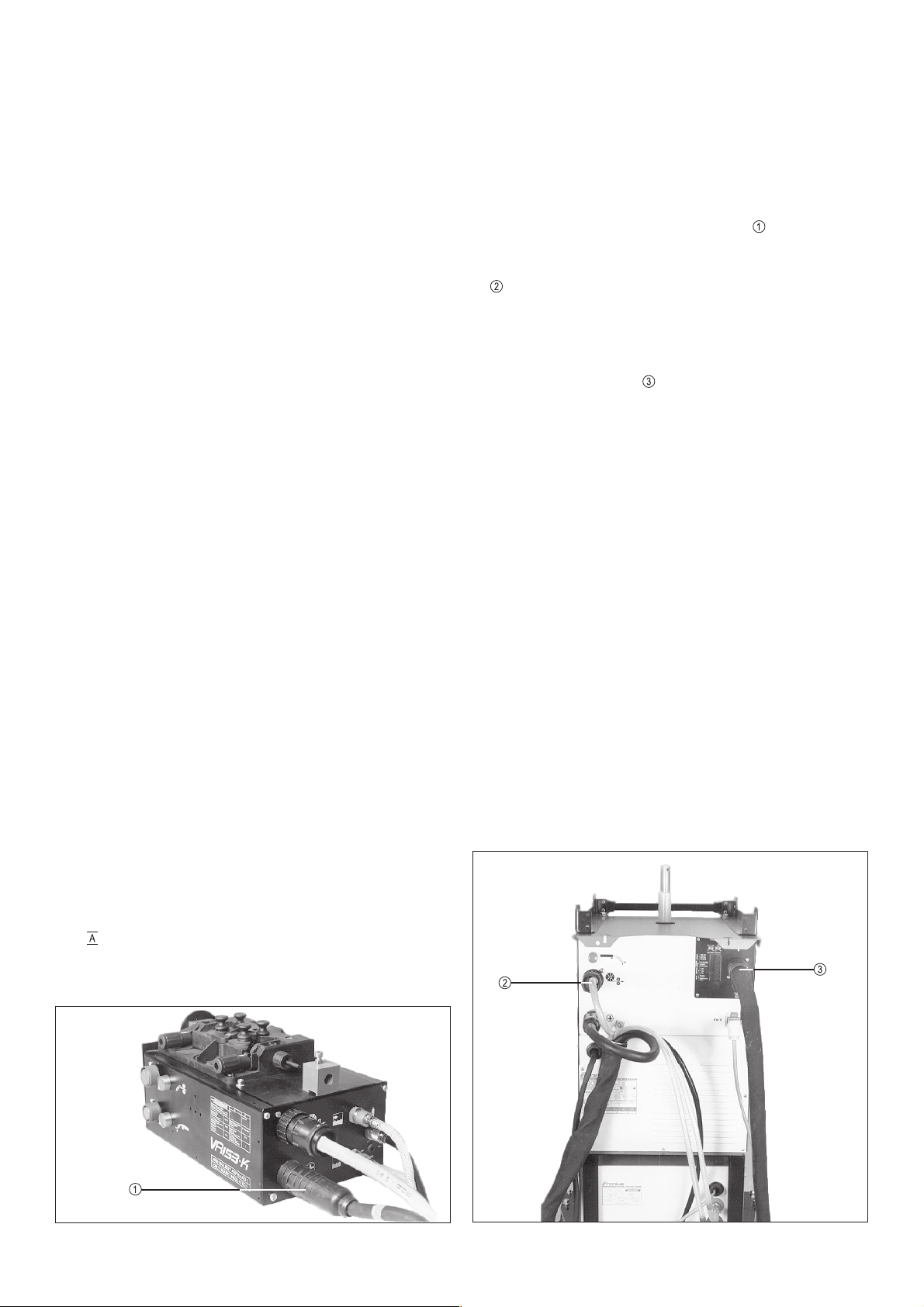
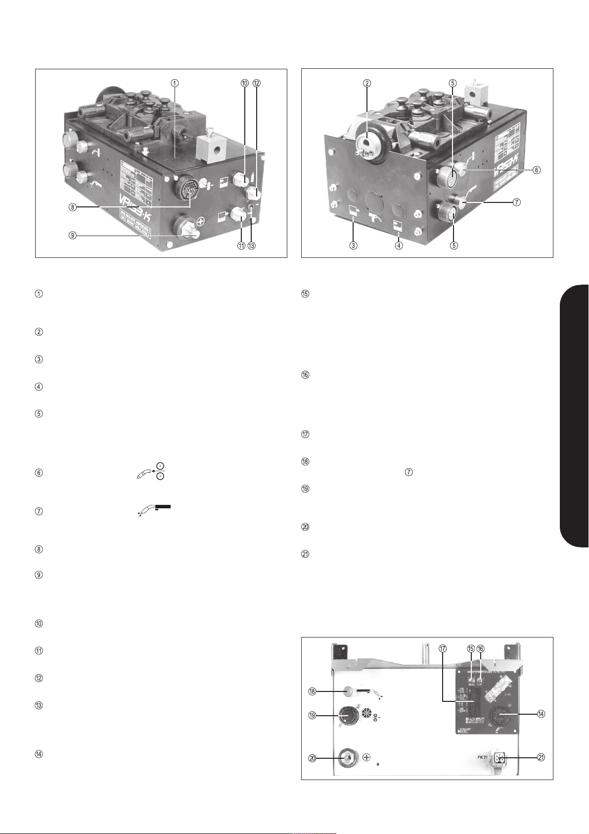
Abb. 3
MOTORPLATTE
Ein speziell drehzahlgeregelter Vorschubmotor gewährleistet
exakte Drahtvorschubgeschwindigkeiten
BRENNER-ZENTRALANSCHLUSS
Fronius, Dinse, Binzel
STECKANSCHLUSS FÜR WASSERVORLAUF
Nur bei Dinse und Binzel Zentralanschluß
STECKANSCHLUSS FÜR WASSERRÜCKLAUF
Nur bei Dinse und Binzel Zentralanschluß
ANSCHLUSSBUCHSE FÜR PUSH-PULL STEUERUNG
(14-poliger Amphenol)
Hier wird der Steuerstecker des Push-Pull Brenners angesteckt. Ebenso können hier ein ext. Gasprüftaster, ein Einschleichtaster sowie vier Signale zum Roboter angeschlossen
werden. Freier Anschluß (4-poliger Amphenol).
DRAHTEINSCHLEICHTASTE
Beim Anwählen dieser Taste läuft der Schweißdraht gas- und
stromlos in das Brennerschlauchpaket ein.
GASPRÜFTASTE
Beim Anwählen dieser Taste kann am Gasdruckminderer die
benötigte Gasmenge eingestellt, bzw. gemessen werden.
ANSCHLUSSBUCHSE FÜR STEUERSIGNALE
37 pol. CPC Verbindung zur Stromquelle
SCHWEISSTROMANSCHLUSS
Bei Sonderschlauchpaketen länger als 8 m muß hier ein Verteilerstück angebracht werden. (2 parallel geführte Stromkabel
verwenden) - positives Schweißpotential
WASSERANSCHLUSS
Wasservorlauf vom Kühlgerät
WASSERANSCHLUSS
Wasserrücklauf vom Kühlgerät
SCHUTZGASANSCHLUSS
Hier ist der Gasfilter aufgeschraubt
EINSTELLSCHRAUBE FÜR GASWÄCHTER (Option)
Mit dieser Einstellschraube kann die Ansprechgasmenge für
die Gasmangelerkennung eingestellt werden (Siehe Anschluß
und Inbetriebnahme der Roboterstromquelle).
ROBOTER-ANSCHLUSSBUCHSE
37 pol. CPC zur Robotersteuerung, siehe Anschlußschema
der Schnittstelle.
Abb. 4
EINSTELLPOTENTIOMETER FÜR ABBRAND
Nur in Verbindung, wenn vom Roboter kein Abbrandsollwert
ausgegeben wird. Bei Beendigung des Schweißvorganges
wird mit einer speziellen elektronischen Schaltung zuerst der
Vorschubmotor- und dann verzögert der Schweißstrom abgeschaltet. Damit wird das Anschmelzen des Drahtendes am
erkalteten Schweißgut verhindert!
Einstellung siehe Sollwerte
EINSTELLPOTENTIOMETER FÜR
TROPFENABLÖSEKORREKTUR
Nur in Verbindung bei TPS im Pulsbetrieb wenn vom Roboter
kein Sollwert dafür ausgegeben wird. Mit der Tropfenablösekorrektur kann der Tropfenablösestrom verändert werden.
SICHTFENSTER FÜR LED-KONTROLLE
Zur optischen Erkennung von Fehlern. Siehe LED-Checkliste
NMI4D.
GASPRÜFTASTE gleiche Funktion wie bei Pos.
ANSCHLUSSBUCHSE FÜR DRAHTVORSCHUB
Neben dem Robotervorschub VR 153-K können hier auch alle
Standardvorschübe für den Handschweißbetrieb angesteckt
werden.
STROMANSCHLUSS
positives Schweißpotential für den Vorschub
KÜHLKREISVERSORGUNG
Nur bei angestecktem Kühlkreis ist ein Schweißbetrieb möglich.
Abb. 5
7
Page 8

TECHNISCHE DATEN
VR 153-K
Schutzart IP 23
Drahtvorschubgeschwindigkeit 0 – 22 m/min;
Untersetzung 24,5 : 1
Drahtvorschubrollen Ø 0,8 – 3,2 mm
Gewicht 6,4 kg
Abmessungen (l x b x h) 370 x 210 x 195
Einsatzdauer (ohne Brenner) 500 A, 60 %
Gasflußwächter
stufenlos einstellbar von 0 – 20 l/min
Gasmagnetventil 42 V CA
Befestigung:
Achtung! Muß isoliert gegen Erde aufgebaut werden.
Befestigung von unten mit Isolationsschrauben.
PERMANENTMAGNETMOTOR (STANDARD)
Nennleistung 160 W
Anker 42 V DC / 3,25 A
Nenndrehzahl 6600 U/min.
Abgabeleistung 80 W
Optoelektronische Drehzahlregelung
VR 153-K T.I.M.E.
Schutzart IP 23
Drahtvorschubgeschwindigkeit 0 – 30 m/min;
Untersetzung 17,6 : 1
Drahtvorschubrollen Ø 0,8 – 3,2 mm
Gewicht 6,4 kg
Abmessungen (l x b x h) 370 x 210 x 195
Einsatzdauer (ohne Brenner) 500 A, 60 %
Gasflußwächter stufenlos einstellbar von
0 – 20 l/min
Gasmagnetventil 42 V CA
Befestigung:
Achtung! Muß isoliert gegen Erde aufgebaut werden.
Befestigung von unten mit Isolationsschrauben. In das
Schweißgerät muß die Option Scheibenläufer eingebaut
werden
SCHEIBENLÄUFERMOTOR
Nennleistung 117,8 W
Versorgung 42 V DC / 4,2 A
Optoelektronische Drehzahlregelung
PUSH-PULL-MOTOR
Erregung permanent
Anker 42 V DC / 0,9 A
I X R Regelung mit Sollwertvorgabe und Überlastabschaltung
8
Page 9

ANSCHLUSSSCHEMA DER SCHNITTSTELLE
DEUTSCH
9
Page 10

SCHALTPLAN
10
Page 11

SCHNITTSTELLENBESCHREIBUNG
ALLGEMEIN
Grundsätzlich können die Funktionen an der Stromquelle mit
einem Signal 24 V DC (+/- 10 %) 0,1 A angesteuert werden
(geeignet für Transistor und Relaisausgänge).
Bei Relaisausgängen kann die 24 V DC Versorgung vom
TS ST153 verwendet werden.
Für die Steuerung der Schweißparameter werden mindestens
zwei analoge Steuerspannungen 0 - 10 V DC 5mA benötigt. Bei
auftretenden Störungen sollten diese Leitungen abgeschirmt
sein.
Die Trennung zwischen Roboter und Sromquelle wird im TS
ST153 mittels Relais durchgeführt (ausgenommen analoge Steu-
ersignale, Stromistwert und Spannungsistwert)
ZUSATZPRINT IROZU
Der Zusatzprint IROZU ermöglicht eine vereinfachte Auswahl der
Signale (high/low) mit Hilfe von acht DIP-Schaltern (Belegung der
DIP-Schalter siehe Tabelle)
DIP-Schalter high low
1 .......... Error off on
2 .......... Error on off
3 .......... Not-Stop off on
4 .......... Not-Stop on off
5 .......... Not-Stop LED off on
6 .......... Not-Stop LED on off
7 .......... No Gas off on
DEUTSCH
Technische Daten
Spulen Nennspannung 24 V DC
Spulenwiderstand 1200 Ohm
Prellzeit 2 ms
Ansprechzeit 8 ms
Abfallzeit 3 ms
Freilaufdiode ist eingebaut
Die Verbindung zwischen Roboter und Stromquelle wird am TS
ST 153 mit einer 37 pol. Steckverbindung durchgeführt. Das
Verbindungskabel sollte 10 m nicht überschreiten.
Der „Zustand“ der Ein- und Ausgangssignale sowie Spannungsversorgungen und Sollwerte können mittels Leuchtdioden auf der
Rückseite der Stromquelle überprüft werden.
a) ARC ON - zeigt Lichtbogenstart des Roboters an
GAS ON - zeigt Gasprüfen des Roboters an
INCHING - zeigt Einschleichbefehl des Roboters an
PULS ON -zeigt Pulsbetrieb an (nur bei TPS)
1)
b) PULS CORR. ............ Tropfenablösekorrektur
VOLT CORR. ............ Lichbogenspannungskorrektur
POWER .................... Leistung1) (Spannung, Draht, Drossel)
BURN BACK ............. Abbrand
1)
(nur TPS)
1)
c) + 10 V, +24 V, -15 V, +15 V
zeigt an, ob Versorgungsspannungen vorhanden sind
d) NO GAS2) (siehe nachfolgendes Kapitel)
ERROR2) (siehe nachfolgendes Kapitel)
EMERGENCY STOP2) (siehe Kapitel „Erläuterung der Steuer-
signale zur Stromquelle“)
1
zeigt Sollwerte 0-10 V des Roboters an, bei min. (0V) LED
dunkel, bei max. (10V) LED hell.
2
leuchten bei Fehlermeldungen der Stromquelle
8 .......... No Gas on off
ERLÄUTERUNG DER STEUERSIGNALE ZUM
ROBOTER
Alle Steuersignale zum Roboter werden durch Relaiskontakte
erzeugt. Es sind immer beide Kontaktbelegungen des Schließkontaktes ausgeführt. Es sollte dabei keine höhere Spannung als
24 V angelegt werden - der Schaltstrom sollte nicht höher als 0,5
A sein.
Gemeinsame Rückleitung für diese Steuersignale ist *--* PIN 34,
wenn DIP-Schalter 1, 7 und 8 eingeschaltet sind.
Diese DIP-Schalter werden im eingeschalteten Zustand (ON)
ausgeliefert.
SIGNAL „STROMFLUSS“
AUSGANG PIN 28 u. 29 (34)
Dieses Signal wird durch einen Arbeitskontakt erzeugt. Dieser
schließt nachdem der Ausgangstrom der Schweißstromquelle zu
fließen beginnt. Er öffnet bei einer Schweißstromunterbrechung
nach einer Verzögerungszeit von ca. 0,15 sek.
SIGNAL „ERROR“
AUSGANG PIN 32 u. 33 (34)
Auf dem Zusatzprint kann mittels DIP-Schalter 1 und Dip-Schalter
2 das Signal „ERROR“ als Öffner oder Schließer ausgewählt
werden. Das Signal überwacht alle Fehlfunktionen und resetiert
die Stromquelle. D. h. Schweißen ist erst wieder nach Behebung
des Fehlers und erneutem Startbefehl möglich.
Das Ändern des Kontaktzustandes kann durch folgende Fehlfunktionen an der Stromquelle hervorgerufen werden.
a) Übertemperatur: bei Überschreitung der Einschaltdauer oder
Fehler am Kühlsystem nach einer Verzögerungszeit von ca. 5
sek.
b) Über/Unterspannung: bei Netzspannungsabweichungen von
+/- 10 % (ab 1991)
c) Motor Reset: bei zu hohem Motorstrom oder Push-Pull Über-
stromset
d) No Program: bei falscher Einstellung der Programmwahl-
schalter (nur bei TS 330)
e) Power on Reset: nach dem Einschalten der Stromquelle für
eine Dauer von 2. sek.
f) Roboterreset: bei einem Not-Stop Befehl des Roboters oder
bei Gasmangel.
11
Page 12

SIGNAL „KEIN GAS“ (nur optionell in Funktion)
AUSGANG PIN 30 u. 31 (34)
Auf dem Zusatzprint kann mittels DIP-Schalter 7 und Dip-Schalter
8 das Signal „KEIN GAS“ als Öffner oder Schließer ausgewählt
werden. Der Kontaktzustand ändert sich, wenn der Durchflußgeber im VR153-K zu geringen Gasdurchfluß während des Schweißens meldet.
Die Anzugsverzögerung beträgt ca. 1 sek.
Dieses Signal bewirkt in der Stromquelle eine automatische Resetierung und wird auch als gesammeltes Error-Signal (siehe
Kap. Signal „Error“) angezeigt.
Hinweis: Nach dem Einschalten der Stromquelle wird automatisch der Gasdruck solange aufgebaut, bis die gewünschte
(eingestellte) Durchflußmenge erreicht ist (max. 12 sek. = 8 m
Schlauchpaket). Die Gasdurchflußüberwachung kann am VR
153-K von 0-20 l/min eingestellt werden.
GRENZWERT SIGNAL (nur optionell in Funktion)
AUSGANG PIN 18 u. 20
Dieses Signal schaltet nur im Arbeitspunktbetrieb (in Verbindung mit QS-Systemen) bei Überschreitung der vorgegebenen
Grenzwerte (Schweißstrom oder Schweißspannung) -> ponten-
tialfreier Schließer-Kontakt.
ERLÄUTERUNG DER STEUERSIGNALE ZUR
STROMQUELLE
Alle Steuersignale vom Roboter sind mit 24 V DC anzusteuern.
Gemeinsame Ader für die Steuersignale ist PIN 27, wenn DIPSchalter 2,3,4,5 u. 6 eingeschaltet sind. Diese DIP-Schalter
werden im eingeschalteten Zustand (ON) ausgeliefert.
BEFEHL FÜR „DRAHTRÜCKZUG“ (OPTION)
EINGANG PIN 3 (muß mit +24 V DC angesteuert werden)
Dieser Befehl von einem Arbeitskontakt in der Robotersteuerung
bewirkt das manuelle Zurückziehen des Drahtes. Der Drahtsollwert wird vom Roboter in Abhängigkeit von der Sollwertleistung
ausgegeben.
Die Funktion dieses Befehls ist nur gewährleistet, wenn kein
Lichtbogenstart- oder Drahteinschleichbefehl gegeben wird und
die OPTION Drahtrückzug eingebaut ist.
PULS / STANDARD UMSCHALTUNG
EINGANG PIN 23 u. 27
Dieser Befehl bewirkt eine Umschaltung vom Standardprogramm
auf ein Pulsprogramm (nur bei TPS in Verwendung). Bei der TS
330/331 bewirkt dieses Signal keine Änderung. Es müssen
jedoch für das entsprechende Material Puls- und Standardprogramme im Eprom vorhanden sein.
BEFEHL „NOT-STOP“ (Tastbetrieb)
EINGANG PIN 25 u. 27
Auf dem Zusatzprint kann mittels DIP-Schalter 3 und DIP-Schalter
4 selektiert werden, ob während des Schweißbetriebes eine
Spannung auf Pin 25 und Pin 27 angelegt sein muß (High- oder
Low-aktiv). Mit dem daneben befindlichen DIP-Schaltern 5 u. 6
werden die NOT-STOP LED´s umgeschaltet!
Dieser Befehl bewirkt schon bei kurzzeitiger Fehlermeldung eine
sofortige Resetierung der Stromquelle. Es kann erst bei erneuter
Startbefehlgabe wieder geschweißt werden.
BEFEHL FÜR „AUSBLASEN“ (OPTION)
Eingang Pin 3 und Pin 4 (muß mit +24 V DC angesteuert werden)
Achtung: Es kann nur entweder die Option „Drahtrückzug“
oder die Option „Ausblasen“ verwendet werden!
BEFEHL „LICHTBOGEN EIN“
EINGANG PIN 17 u. 27
Durch diesen Befehl, den ein Arbeitskontakt in der Robotersteuerung erzeugt, wird der Schweißvorgang gestartet.
Gasvor- und nachströmung können am Motorreglerprint (NMI
3DO) in der Stromquelle (Trimmer) eingestellt werden. Ebenso
kann die Anschleichdrehzahl vor dem Zündbeginn prozentuell
vom Sollwert fix eingestellt werden.
(Siehe Einstellanleitung NMI 3DO)
Bei TS 331 und TPS Anlagen erfolgt diese Einstellmöglichkeit am
Print SMS nach Abschrauben der Progammtabellenplatte.
ABLAUF:
- LICHTBOGEN „EIN“: Gasvorströmung - Leerlaufspannung
Ein - Drahtvorschub Start - Schweißstrom.
- LICHTBOGEN „AUS“: Schweißstrom - Drahtvorschub Stop -
Schweißstrom Aus - Gasnachströmung.
BEFEHL GAS „EIN“
EINGANG PIN 19 u. 27
Durch diesen Befehl wird durch einen Arbeitskontakt im Interface
das Gasmagnetventil angesteuert.
Die Gasdurchflußüberwachung ist dabei nicht in Funktion.
BEFEHL „DRAHTEINSCHLEICHEN“
EINGANG PIN 21 u. 27
Dieser Befehl von einem Arbeitskontakt in der Robotersteuerung,
bewirkt den manuellen Drahtvorschub.
Der Drehzahl-Sollwert hängt vom jeweiligen Schweißprogramm
bzw. der Leistungssollwertstellung ab.
Die beiden Pins sind direkt durchverdrahtet zum 37 pol. CPCStecker an dem der Vorschub angesteckt ist.
Pin 3 é Pin 17 (+24 V DC)
Pin 4 é Pin 18 (GND)
Dieser Befehl bewirkt, das der Brenner mittels Preßluft ausgeblasen wird. Die Funktion dieses Befehls ist nur gegeben, wenn
diese Option eingebaut ist.
SOLLWERTE
Alle Sollwerte werden durch eine DC-Spannung von 0-10 V / 5mA
realisiert. Bezugspunkt ist GND für Sollwerte (PIN 9),
(Verzögerungszeit .... 15 ms)
LEITSPANNUNG FÜR „LICHTBOGENLÄNGENKORREKTUR“
EINGANG PIN 12
Mit dieser Leitspannung kann die Lichtbogenlänge korrigiert
werden. Es wird dabei nur die Lichtbogenspannung, nicht aber
die Drahtvorschubgeschwindigkeit verstellt.
0 V = Lichtbogenspannung -20% (kürzerer Lichtbogen)
5 V = 0 % (gespeicherter Wert)
10 V = Lichtbogenspannung +20% (längerer Lichtbogen)
12
Page 13

LEITSPANNUNG FÜR „SCHWEISSLEISTUNG“
EINGANG PIN 10
Die Schweißleistung hängt vom Sollwert bzw. der Programmstellung ab.
z. B. 0 V = 50 A (min. Schweißstrom für den jeweil. Draht)
5 V = 100 A
10 V = 200 A (max. Schweißstrom für den jeweil. Draht)
LEITSPANNUNG FÜR „ABBRANDZEIT“
EINGANG PIN 13
Durch diesen Sollwert wird die freie Drahtlänge nach der Schweißung bestimmt. Je kürzer die Abbrandzeit, desto länger ist die
freie Drahtlänge.
TS 330 TPS / TS
0 V = 0 sek. 0 V = - 200 ms
5 V = 0,15 sek. 5 V = 0 % programmierter Wert
10 V = 0,3 sek. 10 V = + 200 ms
Wenn dieser PIN nicht angeschlossen wird, kann automatisch
der Wert am Roboterinterface eingestellt werden.
SIGNAL “NAHT-BIT 0”, Wert 1
Pin 24 u. 27
SIGNAL “NAHT-BIT 1”, Wert 2
Pin 22 u. 27
SIGNAL “NAHT-BIT 2”, Wert 4
Pin 2 u. 27,
DEUTSCH
SIGNAL “NAHT-BIT 3”, Wert 8
Pin 1 u. 27
SIGNAL “JOB-BIT 0”, Wert 16
Pin 33 u. 27
SIGNAL “JOB-BIT 1”, Wert 32
Pin 31 u. 27
SIGNAL “JOB-BIT 2”, Wert 64
Pin 29 u. 27
LEITSPANNUNG FÜR „PULSKORREKTUR“
EINGANG PIN 11 (nur bei TPS)
0 V ... minimale Pulskorrektur
5 V ... normale Pulskorrektur
10 V ... maximale Pulskorrektur
Ist der PIN nicht angeschlossen, kann der Wert am Roboterinterface eingestellt werden.
DIGITALES ROBOTERINTERFACE
Das digitale Roboterinterface wird benötigt wenn:
- die Q-Master-Funktionen benötigt werden,
- wenn der Roboter keine analogen Kanäle zur Verfügung hat,
- Arbeitspunkte nicht mehr verstellt werden dürfen, da diese
bereits für eine Schweißnaht optimiert wurden und sich diese
Einstellungen nicht für alle Schweißaufgaben eignen,
- mit unterschiedlichen Schweißprogrammen abwechselnd
ohne Umstellung an der Maschine gearbeitet werden soll,
- mit unterschiedlichen Grenzwerten (Strom, Spannung) gearbeitet wird (z.B. Q-Master),
- Dokumentationen nur für bestimmte Nähte erforderlich sind,
- unterschiedliche Start- und Endkraterparameter notwendig
sind (Startstrom, Endstrom, Startzeit, Endstromzeit).
SIGNAL “JOB-BIT 3”, Wert 128
Pin 26 u. 27
Wird z.B. vom Roboter auf Pin 2, Pin 33 und Pin 26 eine Spannung
von 24V DC angelegt, werden damit Job 9 und Naht 4 angewählt
(1 ist immer Job 0 bzw. Naht 0)
Da nur maximal 10 Jobs vorhanden sind, wird jede Anwahl, die
einen weitern Job anwählen würde nicht berücksichtig. Die Anlage bleibt auf Job 9.
Mittels dieser digitalen Auswahl können maximal 10 Jobs und in
jedem Job maximal 16 Nähte abgerufen werden, somit ergeben
sich 160 Arbeitspunkte. Für nähere Details lesen Sie bitte die QMaster- sowie die LCD-Bedienungsanleitung.
Die beiden Sollwerteingänge “Leistung Pin 10” und “Lichtbogenlängenkorrektur Pin 12” können zum Analogkorrigieren verwendet werden! Diese Funktion muß im Abrufbetrieb angewählt
werden (nur in Verbindung mit Q-Master möglich)!
Gegenüber dem analogen Interface sind beim digitalen Interface
acht weitere Eingänge vorhanden. Diese ermöglichen den Abruf
von Jobs und Nähten. Grundvoraussetzung für diese Funktion ist
die Verwendung eines LCD-Einschubes. Die Q-Master Freischaltung gestaltet den Abruf wesentlich komfortabler und ist
daher sinnvoll.
Hinweis! Auf dem Interface fallen Pin 1 und Pin 2 als freie
Leitungen weg, da diese für die Nahtanwahl benötigt werden.
Achtung! Wenn sich ein digitales Roboter-Interface in der
Stromquelle befindet muß sichergestellt sein, daß der
Roboter über die nötigen Digitalausgänge verfügt! Wird
hier eine Analogkarte angesteckt besteht die Gefahr, daß
diese zerstört wird. Daher beim Tausch der Stromquelle
darauf achten, daß in der Ersatzstromquelle ein Interface
gleicher Konfiguration verwendet wird.
13
Page 14
AUSGABE VON SCHWEISSPARAMETERN
UND VERSORGUNGSSPANNUNGEN
ANSCHLUSS UND INBETRIEBNAHME DER
ROBOTERSTROMQUELLE
SCHWEISSSTROMISTWERT
AUSGANG PIN 16
Hier kann eine galvanisch getrennte Gleichspannung überwacht
werden. Diese Spannung entspricht dem Schweißstrom 1 V = 100 A
(z.B. für Nahtsuchsystem).
Bezugspunkt für diese Spannung ist PIN 9 (Gnd.-Sollwerte)
SCHWEISSPANNUNG ISTWERT
AUSGANG PIN 14, 15
Diese Spannung ist direkt mit den Schweißbuchsen verbunden.
Es werden hier Spannungen von 0 - 60 V DC während des
Schweißvorganges anliegen (z.B. für Drahtfestbrandkontrolle)
VERSORGUNG + 15 V
AUSGANG PIN 7
Maximale Strombelastung 50 mA (Absicherung 125 mA)
(z.B. für Versorgung der Analogausgangskarte)
VERSORGUNG - 15 V
AUSGANG PIN 8
Maximale Strombelastung 50 mA (Absicherung 125 mA)
VERSORGUNG + 24 V
AUSGANG PIN 5
Maximale Strombelastung 500 mA (Absicherung 630 mA)
(z.B. zur Ansteuerung der Relais am Interface)
GND FÜR VERSORGUNGEN
AUSGANG PIN 6
Gemeinsame Rückleitung für Versorgungsspannungen.
DURCHGESCHLIFFENE LEITUNGEN zum VR 153-K
(Push Pull Anschluß)
AUSGÄNGE oder EINGÄNGE 1,2,36,37
Maximale Strombelastung: Leitungen 1 u. 2 500 mA / 24 V
(Leitungen 1 u. 2 nur bei analogem Interface verfügbar!)
Leitungen 36 u. 37 1A / 42 V
Hier können verschiedenste Signale vom Brenner zur Robotersteuerung oder umgekehrt belegt werden.
ROBOTERERKENNUNG
BRÜCKE PIN 4 und PIN 35
(bei neuen Geräten nicht erforderlich; ab Seriennr. 060000)
(Automatische Umschaltung der Sollwerte von hand auf Roboterbetrieb, sobald Robotersteuerung angesteckt wird). Die Umschal-
tung im Interface erfolgt, wenn an diesem PIN +24V (d. h. Brücke
zwischen PIN 35 und PIN 4) angelegt werden. Bei neuen Geräten
fehlt diese Einrichtung („Interface Print ohne Relais“ siehe Abb. 9
Pos. )
- Vorschubgerät VR 153-K isoliert auf den Roboter aufbauen Isolationsschrauben und Pertinaxplättchen verwenden. Bei
einer Verbindung des Vorschubgehäuses mit dem Werkstück
kann bei einem „Drahtwickel“ ein Kurzschluß im Vorschub
entstehen - Verschweißung des Gehäuses.
- Verbindungsschlauchpaket am Vorschub
Lasche am Roboterarm befestigen
- Verbindungsschlauchpaket verlegen und an der Stromquelle
anschließen
- Brenner am Zentralanschluß des VR 153-K anschließen und
befestigen
- Roboteranschlußleitung im Roboter anklemmen
- Roboteranschlußleitung
- Stromquelle laut Geräte-Bedienungsanleitung einstellen und
in Betrieb nehmen.
Nach dem Einschalten leuchtet die Übertemperatur LED für
einige Sekunden auf, da sich die Kühlwassersäule erst aufbauen muß.
- Gasdurchflußüberwachung einstellen (Option)
- Verstellschraube nach links herausdrehen
- gewünschte Gasdurchfluß am Druckregler einstellen
- Druckhebel im VR 153-K öffnen
- Lichtbogen-Ein-Befehl geben und Verstellschrauben nach
rechts langsam einschrauben bis NO GAS-LED am Interface aufleuchtet
- Verstellschraube eine Umdrehung nach links drehen
- Programmierung einer Grundeinstellung der Analogausgangskarte für eine Probeschweißung
LICHTBOGENKORREKTUR 5 V
ABBRANDZEIT 2 V (bei TPS 5 V)
TROPFENABLÖSEKORREKTUR 5 V (nur bei TPS)
LEISTUNG je nach Material-
SCHWEISSGESCHWINDIGKEIT 20 - 50 cm/min.
Prinzip des MIG/MAG Verfahrens und Sicherheitsmaßnahmen
sind der Anleitung der Stromquelle zu entnehmen.
anstecken
anstecken bzw.
stärke 0 - 10 V
Abb. 6 Abb. 7
14
Page 15

UMRÜSTEN EINER TS od. TPS AUF
ROBOTERBETRIEB
- Gerät ausschalten, Netzstecker ziehen
- Vorschubgerät und Verbindungsschlauchpaket abnehmen
- Blindabdeckung auf der Rückseite, sowie rechten Seitendekkel der Stromquelle abschrauben.
- Einschub von außen vorsichtig einschieben und mit 4 Blechschrauben befestigen.
- Verbindungskabel
24 polig und 2 polig am Interfaceprint
14 polig, 6 polig und 2 polig am NMI
2 poliges Kabel vom X11 auf 16 poliges am NMI 4.
- Nur digitales Roboter-Interface: 24-poligen Molex-Stecker vom
Print DIGIR am Einschubprint SML 4A, Steckerleiste X11
anstecken.
- Nur bei Option „Ausblasen“: Am Stecker X11 Pin 3+4 herausziehen und die beiden freien Stecker des Kabelbaumes dort
hineinstecken (auf Beschriftung achten!).
An Stecker X9 Pin 17+19 herausziehen und die beiden freien
Stecker des Kabelbaumes dort hineinstecken (auf Beschrif-
tung achten!).
- GND am Interface anstecken
Dazu die GND-Leitung von der Blindabdeckung verwenden
- Verbindungskabel zum Vorschubstecker
einstecken. CPC Kontakte im Vorschubstecker X9 einstecken.
Leitung 1 ... X9 PIN 19
Leitung 2 ... X9 PIN 20
Leitung 5 ... X9 PIN 36
Leitung 6 ... X9 PIN 33
- Einstecken des STF-Relais (Spulenanschlüsse zur Printmitte)
im NMI 3DO
- 2 Verbindungen vom Roboterstecker X11 im Vorschubstecker
X9 einstecken.
Leitung von X11 PIN 36 auf X9 PIN 34.
Leitung von X11 PIN 37 auf X9 PIN 35.
- Blindkontakt
- VR 153-K mit Zwischenschlauchpaket anschließen
(siehe Inbetriebnahme)
- Wechsel des FK 71 (siehe Bedienungsanleitung Stromquelle)
oder Einbau eines Strömungswächters. Best. Nr. 4.100.025
zum NMI anstecken
(6 poliger Stecker)
. Bei NMI4. ist Relais bereits bestückt.
auf Vorschubstecker X9 PIN 37 einstecken.
FUNKTION DER BAUGRUPPEN
STROMQUELLE
- VM 34. Sicherungsprint
Versorgungsspannungen für Elektronik
- NMI Motorreglerprint
a) vergleicht den Sollwert und Istwert der Motordrehzahl
b) steuert Gas und schaltet den Schweißstrom der Stromquel-
le ein
c) koordiniert die einzelnen Steuerabläufe
d) Anschlußmöglichkeit für Push-Pull Regler
e) versorgt Elektronik mit stabilisierten, kurzschlußfesten
Gleichspannungen
- Thyristormodul Print BM 34 / 45
Stellglied für die Ankerspannung
- PUSH-PULL Motorregler PMR 3. (OPTION)
dient zur getrennten Regelung des Push-Pull-Motors
Verschiedene Typen: FRONIUS, BINZEL, DINSE
- IRO 34. Interfaceprint
stellt Verbindung zwischen Stromquelle und Robotersteuerung her.
VR 153-K
- Preßluftmagnetventil (nur bei Option „Ausblasen“ eingebaut)
- Gasdurchflußwächter
überwacht den Gasfluß und gibt ein Signal an das Interface,
wenn die eingestellte Gasflußmenge unterschritten wird.
- Gasmagnetventil 42 V AC
steuert den Gasdurchfluß
- IWGT-C Istwertgeberprint
optoelektronische Istwerterfassung
- Antriebsmotor
mit Schneckengetriebe 24 : 1
AUSTAUSCH DES PRINTES NMI oder IRO 34.
Beim Austausch ist keine Justierung notwendig.
Bedingt durch Lagerung oder Transport empfiehlt es sich jedoch,
die angezeigte Drahtvorschubgeschwindigkeit (Display an der
Front der Stromquelle) mit dem Drahtvorschubistwert zu vergleichen.
DEUTSCH
NMI 3DO
X9
X11
Abb. 8 Innenansicht der Stromquelle Abb. 9 Robotereinschub Interface
15
Page 16

LED-CHECKLISTE NMI 4D
S1 / 5
LED-Anzeige +10V
muß bei eingeschaltetem Gerät
immer leuchten
LED-Anzeige +15V
muß bei eingeschaltetem Gerät
immer leuchten
ansonst F6 defekt
CODIERSCHALTER
LED-Anzeige BRT 2
leuchtet bei gedrückter
Brennertaste 2 (zur Zeit
nicht verwendet.)
LED-Anzeige BRT
leuchtet bei gedrückter
Brennertaste
LED-Anzeige VORSCHUB A
LED-Anzeige EINSCHLEICHEN
leuchtet bei gedrückter
leuchtet bei verwendeter Doppel-
Einschleichtaste
vorschubsteuerung, wenn auf
Vorschub A geschaltet ist
LED-Anzeige GASPRÜFEN
leuchtet bei gedrückter
Gasprüftaste
LED-Anzeige +5V
muß bei eingeschaltetem Gerät
immer leuchten
LED-Anzeige -15V
muß bei eingeschaltetem Gerät
immer leuchten
ansonst F6 defekt
ansonst F7 defekt
SOLLWERT - DRAHTVORSCHUB
Helligkeit der LED-Anzeige
nimmt mit steigendem
Sollwert zu
MOTORBREMSE
LED-Anzeige leuchtet,
wenn Vorschubmotor
gebremst wird
LED-Anzeige leuchtet ca. 10 Sek.:
LED-Anzeige leuchtet,
wenn LEERLAUFSPANNUNG
anliegt
Netzunterspannung von +/-10 %
des Gerätes.
a) bei Auftreten einer Netzüber- bzw.
b) bei einem Übertemperaturfehler
für die Zeitdauer von 1 Sek.
MOTOR - RESET
LED-Anzeige leuchtet:
Drahtvorschubmotoren
a) nach Einschalten der Anlage
b) nach Überstrom an den
Achtung! Nichtbezeichnete Einstellregler dürfen nur vom Werk eingestellt werden!
Abb. 11 LED-Checkliste und Beschreibung der Einstellregler am Netzteil-Motorreglerprint NMI 4D
16
STROMFLUSS-SIGNAL
LED-Anzeige leuchtet,
wenn Schweißstrom fließt
Page 17

LED-KONTROLLE AM INTERFACE UND FEHLERSUCHE
POWER
Die Helligkeit der LED-Anzeige wird vom Sollwert der Schweißleistung bestimmt.
LED dunkel .. 0 V Sollwert auf X 11/10
LED mittel .... 5 V Sollwert auf X 11/10
LED hell ....... 10 V Sollwert auf X 11/10
BURN BACK
Die Helligkeit der LED-Anzeige wird vom Sollwert der Abbrandzeit bestimmt.
LED dunkel .. 0 V Sollwert auf X 11/13
LED mittel .... 5 V Sollwert auf X 11/13
LED hell ....... 10 V Sollwert auf X 11/13
Wenn X 11/13 nicht belegt wird oder X 11 abgesteckt ist, läßt sich
dieser Sollwert mit dem Burn-Back Pot am Interface einstellen.
+10V, +24V, -15V, +15V
Diese LED’s müssen grün leuchten, sobald die Maschine eingeschaltet ist. Es werden die Versorgungsspannungen vom NMI
Print angezeigt.
VALUES
COMMAND
SUPPLIES ORDERS
FAULTS
ARC ON
GAS ON
INCHING
PULS ON
PULS CORR.
VOLT CORR.
POWER
BURN BACK
+ 10V
+ 24V
- 15V
+ 15V
NO GAS
ERROR*
EMERGENCYSTOP
ROBOTERINTERFACE TS-ST 153
0
0,2
0,1
00,3
ANALOG INTERFACE
DIGITAL INTERFACE
+1-1
+2-2
PULS CORR.BURN BACK
RS 232
DEUTSCH
* OVER-UNDER-VOLTAGE
OVER-TEMPERATURE
MOTOR-RESET
WATER/GAS FAULT
Abb. 12
ARC ON
grüne LED-Anzeige leuchtet, wenn vom Roboter ein Startsignal
gegeben wird.
Test: X11/27 auf X11/6 und X11/27 auf X11/5
GAS ON
grüne LED-Anzeige leuchtet, wenn vom Roboter ein Befehl für
Gasprüfen gegeben wird.
Test: X11/27 auf X11/6 und X11/19 auf X11/5
INCHING
grüne LED-Anzeige leuchtet, wenn vom Roboter ein Befehl für
Einschleichen gegeben wird.
Test: X11/27 auf X11/6 und X11/21 auf X11/5
PULSE ON
grüne LED-Anzeige leuchtet, wenn vom Roboter ein Befehl für
Pulsbetrieb gegeben wird.
Test: X11/27 auf X11/6 und X11/23 auf X11/5
PULSE CORR.
Die Helligkeit der LED-Anzeige wird vom Sollwert der Pulskorrektur bestimmt.
LED dunkel .. 0 V Sollwert auf X 11/11
LED mittel .... 5 V Sollwert auf X 11/11
LED hell ....... 10 V Sollwert auf X 11/11
Wenn X 11/11 nicht belegt wird oder X 11 abgesteckt ist, läßt sich
dieser Sollwert mit dem Pulskorrekturpot am Interface einstellen.
NO GAS
Rote LED-Anzeige leuchtet, wenn während des Schweißvorganges kein - oder zu wenig Schutzgas strömt.
ERROR
Rote LED-Anzeige leuchtet, wenn von der Stromquelle eine
Fehlermeldung kommt (Siehe Erläuterungen der Steuersignale
der Stromquelle).
EMERGENCY STOP
Rote LED-Anzeige leuchtet, wenn von der Roboter-Steuerung ein
NOT-STOP Befehl gegeben wird.
VOLT CORR.
Die Helligkeit der LED-Anzeige wird vom Sollwert der Lichtbogenlängenkorrektur bestimmt.
LED dunkel .. 0 V Sollwert auf X 11/12
LED mittel .... 5 V Sollwert auf X 11/12
LED hell ....... 10 V Sollwert auf X 11/12
17
Page 18

LEDANZEIGEN AN DER FRONTSEITE
EMPFOHLENE SERVICEARBEITEN
NETZ LED
Grüne LED Anzeige leuchtet, wenn die Netzversorgungsspannungen vorhanden sind und das Gerät eingeschaltet ist.
ÜBERSPANN.-LED
Rote LED Anzeige leuchtet, wenn die Netzversorgung +/-10 %
vom Normwert abweicht.
ÜBERTEMP.-LED
Rote LED Anzeige leuchtet, wenn bei einem Fehler am Kühlsystem oder wenn die Einschaltdauer der Maschine überschritten
wurde.
WECHSELN DES EINSCHUBES Abb. 13
- Hauptschalter ausschalten
- Robotersteuerung abstecken
- Optionsplatte von rückwärts herausnehmen
- Steckverbindungen abstecken
WÖCHENTLICH
- Kühlflüssigkeit (falls vorhanden)
- Zustand des Schweißbrenners
- Drahteinlauf und Drahtfördersystem
JÄHRLICH
- Ausblasen des Drahtvorschubgerätes mit trockener Preßluft
- Kontrolle der mechanischen Teile
- Einstellbereich der Motordrehzahl
- allgemeine Kontrolle
- Kontrolle des Gasfilters (nur bei Option Gaswächter)
Abb. 13
HERAUSNAHME DER MOTORPLATTE: Abb. 14
l Hauptschalter ausschalten
l 4 Befestigungsschrauben der Motorplatte öffnen
l Motorplatte leicht nach links drehen und am Zentralanschluß
zuerst anheben
l Istwertgeber abstecken
Abb. 14
18
Page 19

OPERATING INSTRUCTIONS
ENGLISH
1
Page 20

2
Page 21

DEAR FRONIUS CUSTOMER
This brochure is intended to familiarise you with how to operate
and maintain your Roboterinterface TSST 153. You will find it well
worthwhile to read through the manual carefully and to follow all
the instructions it contains. This will help you to avoid operating
errors - and the resultant malfunctions. Your machine will repay
you by giving you constant operational readiness for many years
to come.
FRONIUS SCHWEISSMASCHINEN
VERTRIEB GMBH & CO KG
Warning! The machine may only be put into service by
trained personnel, and only in accordance with the technical directions. Before you start using the machine, you
must read the section headed "Safety rules".
CONTENTS
Dear Fronius Customer ................................................................................... 3
Safety rules .....................................................................................................4
Outline of basic principle .................................................................................6
Description of controls ..................................................................................... 7
Technical data .................................................................................................. 8
Interface connection scheme ........................................................................... 9
Circuit diagram ............................................................................................. 10
General description of interface .....................................................................11
Additional IROZU board ................................................................................11
Control signals to robot - explanatory notes ................................................. 11
Control signals to power source-explanatory notes.................................... 12
Command values ......................................................................................... 12
Digital robot interface .................................................................................... 13
Output of welding parameters and supply voltages .................................... 14
Connecting and starting up the robot power source .................................... 14
Converting a TS or TPS to robot operation ................................................. 15
Function of the assemblies ........................................................................... 15
LED Checklist NMI 4D ................................................................................ 16
LED checks on the interface; troubleshooting.............................................. 17
Recommended service jobs ........................................................................ 18
Mode d´emploi .............................................................................................. 53
Spare parts list ............................................................................................. 53
Circuit Diagram ............................................................................................ 53
Fronius - Sales and service offices ............................................................. 53
ENGLISH
3
Page 22

SAFETY RULES
GENERAL REMARKS
This welding machine has been made in accordance with the state of the
art and all recognised safety rules. Nevertheless, incorrect operation or
misuse may still lead to danger for
- the life and well-being of the welder or of third parties,
- the welding machine and other tangible assets belonging to the
owner/operator,
- efficient working with the welding machine.
All persons involved in any way with starting up, operating, servicing and
maintaining the welding machine must
- be suitably qualified
- know about welding and
- follow exactly the instructions given in this manual.
Any malfunctions which might impair machine safety must be eliminated
immediately.
It’s your safety that’s at stake!
UTILISATION FOR INTENDED PURPOSE ONLY
The welding machine may only be used for jobs as defined by the
“Intended purpose” (see the section headed "Starting to use the welding
machine").
Utilisation in accordance with the “Intended purpose” also comprises
- following all the instructions given in this manual
- performing all stipulated inspection and servicing work
OBLIGATIONS OF OWNER/OPERATOR
The owner/operator undertakes to ensure that the only persons allowed
to work with the welding machine are persons who
- are familiar with the basic regulations on workplace safety and
accident prevention and who have been instructed in how to operate
the welding machine
- have read and understood the sections on safety and the warnings
contained in this manual, and have confirmed as much with their
signatures
Regular checks must be performed to ensure that personnel are still
working in a safety-conscious manner.
OBLIGATIONS OF PERSONNEL
Before starting work, all persons entrusted with carrying out work on the
welding machine shall undertake
- to observe the basic regulations on workplace safety and accident
prevention
- to read the sections on safety and the warnings contained in this
manual, and to sign to confirm that they have understood these
PERSONAL PROTECTIVE EQUIPMENT
For your personal safety, take the following precautions:
- Wear stout footwear that will also insulate even in wet conditions
- Protect your hands by wearing insulating gloves
- Protect your eyes from UV rays with a safety shield containing
regulation filter glass
- Only use suitable (i.e. flame-retardant) clothing
- Where high noise levels are encountered, use ear-protectors
Where other persons are nearby during welding, you must
- instruct them regarding the dangers,
- provide them with protective equipment and/or
- erect protective partitions or curtains.
HAZARDS FROM NOXIOUS GASES AND VAPOURS
- Extract all fumes and gases away from the workplace, using suitable
means.
- Ensure a sufficient supply of fresh air.
- Keep all solvent vapours well away from the arc radiation.
HAZARDS FROM FLYING SPARKS
- Move all combustible objects well away from the welding location.
- Welding must NEVER be performed on containers that have had
gases, fuels, mineral oils etc. stored in them. Even small traces of
these substances left in the containers are a major explosion hazard.
- Special regulations apply to rooms at risk from fire and/or explosion.
Observe all relevant national and international regulations.
HAZARDS FROM MAINS AND WELDING CURRENT
- An electric shock can be fatal. Every electric shock is hazardous to
life.
- Magnetic fields generated by high amperages may impair the functioning of vital electronic devices (e.g. heart pacemakers). Users of
such devices should consult their doctors before going anywhere
near the welding workplace.
- All welding cables must be firmly attached, undamaged and properly
insulated. Replace any loose connections and scorched cables immediately.
- Have the mains and the appliance supply leads checked regularly by
a qualified electrician to ensure that the PE conductor is functioning
correctly.
- Before opening up the welding machine, make absolutely sure that
this is "dead". Discharge any components that may store an electrical
charge.
- If work needs to be performed on any live parts, there must be a
second person on hand to switch of the machine at the main switch
in an emergency.
PARTICULAR DANGER SPOTS
- Do not put your fingers anywhere near the rotating toothed wheels of
the wirefeed drive.
- Special regulations apply to rooms at risk from fire and/or explosion.
Observe all relevant national and international regulations.
- Welding machines for use in spaces with increased electrical danger
(e.g. boilers) must be identified by the “S” (for safety) mark.
- Welding-joins to which special safety requirements apply must only
be carried out by specially trained welders.
- When hoisting the power source by crane, always attach the chains
or ropes to the hoisting lugs at as close an angle to the vertical as
possible. Before hoisting, remove the gas cylinder and the wirefeed
unit.
- When hoisting the wirefeed unit by crane, always use an insulating
suspension arrangement.
INFORMAL SAFETY PRECAUTIONS
- The instruction manual must be kept at the welding-machine location
at all times.
4
Page 23

- In addition to the instruction manual, copies of both the generally
applicable and the local accident prevention and environmental
protection rules must be kept on hand, and of course observed in
practice.
- All the safety instructions and danger warnings on the welding
machine itself must be kept in a legible condition.
ALTERATIONS TO THE WELDING MACHINE
- Do not make any alterations, installations or modifications to the
welding machine without getting permission from the manufacturer
first.
- Replace immediately any components that are not in perfect condition.
SAFETY PRECAUTIONS AT THE INSTALLATION
LOCATION
- The welding machine must be placed on an even, firm floor in such a
way that it stands firmly. A welding machine that topples over can
easily kill someone!
- Special regulations apply to rooms at risk from fire and/or explosion.
Observe all relevant national and international regulations.
- By means of internal instructions and checks, ensure that the workplace and the area around it are always kept clean and tidy.
VAGRANT WELDING CURRENTS
- Ensure the workpiece clamp is connected tightly to the workpiece
- Set the welding machine up insulated where the floor conducts
electricity
If these instructions are not followed vagrant welding currents occur,
these can destroy earthed conductor terminals and other electrical
equipment.
SAFETY PRECAUTIONS IN NORMAL OPERATION
- Only operate the welding machine if all its protective features are fully
functional.
- Before switching on the welding machine, ensures that nobody can
be endangered by your turning on the machine.
- At least once a week, check the machine for any damage that may be
visible from the outside, and check that the safety features all function
correctly.
SAFETY INSPECTION
The owner/operator is obliged to have the machine checked for proper
condition by a trained electrician after any alterations, installations of
additional components, modifications, repairs, care and maintenance,
and in any case at least every twelve months.
SPARES AND WEARING PARTS
- Use only original spares and wearing parts. With parts sourced from
other suppliers, there is no certainty that these parts will have been
designed and manufactured to cope with the stressing and safety
requirements that will be made of them.
- When ordering spare parts, please state the exact designation and
the relevant part number, as given in the spare parts list. Please also
quote the serial number of your machine.
CALIBRATION OF WELDING MACHINES
In view of international standards, regular calibration of welding machinery is advisable. Fronius recommends a 12-month calibration interval.
For more information, please contact your Fronius partner!
CE-MARKING
The welding machine fulfils the fundamental requirements of the LowVoltage and Electromagnetic Compatibility Directive and is thus CEmarked.
COPYRIGHT
Copyright to this instruction manual remains the property of Fronius
International GmbH&Co.KG.
Text and illustrations are all technically correct at the time of going to
print. Right to effect modifications is reserved. The contents of the
instruction manual shall not provide the basis for any claims whatever on
the part of the purchaser. If you have any suggestions for improvement,
or can point out to us any mistakes which you may have found in the
manual, we should be most grateful.
ENGLISH
In the course of such inspection, the following regulations must be
observed (as a minimum):
- IEC (EN) 60 974-1 - Arc welding equipment - Part 1: Welding power
sources
- VBG 4, §5 - Electrical plant and apparatus
- VBG 15, §33 / §49 - Welding, cutting and allied processes
- VDE 0701-1 - Repair, modification and inspection of electrical
appliances; general requirements
- VDE 0702-1 - Repeat tests on electrical appliances
Further information on corrective maintenance, modification and
inspection of welding machines is available from your regional or national
Fronius service centre,who will be pleased to provide you with a copy of
the Work Instruction “Safety Inspection of Welding Machinery” (AAPMÜ-01) upon request.
ud_fr_st_sv_00146 0120015
Page 24

OUTLINE OF BASIC PRINCIPLE
POWER SOURCE TS / TPS
COOLING UNIT FK 71 with watercontroler
ROBOTERINTERFACE
ROBOT CONTROL
ROBOT
Fig. 1 Standard equipment
VR 153-K with adjustable gascontroler
TORCH
INTERCONNECTION CABLE ASSEMBLY 4m / 8m
(optional length possible)
CONNECTION LEAD TO ROBOT
POWER SOOURCE TS / TPS
with integrated Push-Pull regulator
COOLING UNIT FK 71 with watercontroler
ROBOTERINTERFACE
ROBOT CONTROL
ROBOT
Fig. 2 Push-Pull torch equipment
VR 153-K with adjustable gascontroler
PUSH-PULL TORCH
INTERCONNECTION CABLE ASSEMBLY 4m / 8m
(optional length possible)
CONNECTION LEAD TO ROBOT
6
Page 25
DESCRIPTION OF CONTROLS
For details of the controls on the power source, see the manual for this power source.
Fig. 3
MOTOR BASEPLATE
A specially speed-controlled feed motor ensures highly exact
wirefeed speeds.
CENTRAL TORCH CONNECTION
Fronius, Dinse, Binzel
PLUG-IN CONNECTION FOR WATER FLOW
Only with Dinse and Binzel central connection
PLUG-IN CONNECTION FOR WATER RETURN FLOW
Only with Dinse and Binzel central connection
PUSH-PULL SOCKET (14-pole Amphenol)
The control plug of the push-pull torch is plugged in here. An
external gas-test button, a wire-inch button and four signals to
the robot can also be connected here. Free connector (4-pole
Amphenol).
WIRE-INCH BUTTON
When this button is pressed, the welding wire is fed into the
torch hosepack without gas and without welding current.
GAS-TEST BUTTON
When this button is pressed, the required gas flow rate can be
set and/or measured on the gas pressure regulator.
SOCKET FOR CONTROL SIGNALS
37-pin CPC connection to power-source
WELDING CURRENT CONNECTION
Where special hosepacks longer than 8 m are used, a splitter
must be attached here. (Use 2 parallel current cables) - positive
welding potential.
WATER CONNECTION
For water flow from cooling unit
WATER CONNECTION
For water return flow to cooling unit
SHIELDING GAS CONNECTION
The gas filter is screwed on here.
ADJUSTING SCREW FOR GAS MONITOR (Optional)
The critical gas floe rate at which the “no gas” warning is
triggered is set by means of this adjusting screw. (See chapter
“Connecting and starting up the robot power source”).
ROBOT SOCKET
37-pin CPC to the robot control unit - see chapter “Interface
connection scheme”.
Fig. 4
ADJUSTING POTENTIOMETER FOR BURN-BACK
Only in use when no burn-back command value is outputted by
the robot. When the welding operation is completed, a special
electronic circuit switches off first the wirefeed motor, and then
- after a time-lag - the welding current. This prevents the end of
the wire solidifying onto the cooled welding deposit!
Adjusting see chap. “Command values”
ADJUSTING POTENTIOMETER FOR
PULSE CORRECTION
Only in use on TPS and when no pulse-correction command
value is outputted by the robot. The pulse correction makes it
possible to compensate for longer hose-pack lengths.
WINDOW FOR LED CHECKS
For alerting the user to errors. See ”LED-checklist NMI4D“.
GAS-TEST BUTTON
Identical function to N°
SOCKET FOR WIREFEED UNITS
Beside the VR 153-K robot wirefeed, any other standard
manual welding wirefeed may also be connected here.
CURRENT CONNECTION
positive welding potential for the wirefeed unit
POWER SUPPLY TO COOLING UNIT
Welding is only possible when the cooling unit is plugged in.
Fig. 5
ENGLISH
7
Page 26

TECHNICAL DATA
VR 153-K
Type of protection IP 23
Wirefeed speed 0 – 22 m/min;
reduction ratio 24,5 : 1
Wirefeed rollers Ø 0,8 – 3,2 mm
Weight 6,4 kg
Dimensions (l x w x h) 370 x 210 x 195
Duty cycle (without torch) 500 A, 60 %
Gas-flow monitor
continuously adjustable from 0 – 20 l/min
Solenoid valve 42 V CA
How fixed:
Warning! Must be set up so as to be insulated from earth
(i.e. fixed from below with insulating screws)
PERMANENTMOTOR - STANDARD
Rated output 160 W
Armature 42 V DC / 3,25 A
Rated speed 6600 rpm
Power output 80 W
Optoelectronic speed control
VR 153-K T.I.M.E.
Type of protection IP 23
Wirefeed speed 0 – 30 m/min;
reduction ratio 17,6 : 1
Wirefeed rollers Ø 0,8 – 3,2 mm
Weight 6,4 kg
Dimensions (l x w x h) 370 x 210 x 195
Duty cycle (without torch) 500 A, 60 %
Gas-flow monitor
continuously adjustable from 0 – 20 l/min
Solenoid valve 42 V CA
How fixed:
Warning! Must be set up so as to be insulated from earth
(i.e. fixed from below with insulating screws)
For this wire feeder the optional, motor regulator card for
disk motor, must be built in into the power source.
DISC MOTOR
Rated output 117,8 W
Armature 42 V DC / 4,2 A
Optoelectronic speed control
PUSH-PULL MOTOR
Excitation permanent
Armature 42 V DC / 0,9 A
I X R control with present command value and overloaded cut-out
8
Page 27

INTERFACE CONNECTION SCHEME
ENGLISH
9
Page 28

CIRCUIT DIAGRAM
10
Page 29

GENERAL DESCRIPTION OF INTERFACE
ADDITIONAL IROZU BOARD
The functions on the power source can all be actuated with a
24 V DC (+/- 10 %) 0,1 A signal (suitable for transistor and relay
outputs). For relay outputs, the 24 V DC supply from the TS ST153
can be used.
At least two 0 - 10 V DC 5mA analogue control voltages are
needed to control the welding parameters . If there is any interference, these leads should be shielded.
On the TS ST153, the robot and the power source are separated
by relays (except for analouge control signals, actual current and
actual voltage values).
Techncal data
Coils, rated voltage 24 V DC
Coil resistance 1200 Ohm
Bouncing time 2 ms
Responce time 8 ms
Releasing time 3 ms
There is a built-in free-wheeling diode
Ont the TS ST 153 the robot and the power source are linked via
a 37-pole plug-in connection. The connecting cable should not be
longer than 10 m.
The status of the input and output signals, and of voltage supply
and command values, can be checked by referring to the LEDs at
the back of the power source.
a) ARC ON - indicates that an arc has started on the robot
GAS ON - indicates that robot is giving ”gas check“ command
INCHING - indicates that robot is giving ”wire-inch“ command
PULS ON - indicates that the pulsed-arc mode is operational
(only on TPS)
1
1
(only on TPS)
1
b) PULS CORR. ............ pulse correction
VOLT CORR. ............ arc voltage correction
POWER .................... power1 (voltage, wire, inductance)
BURN BACK ............. burn-back
c) +10 V, +24 V, -15 V, + 15 V
indicates whether supply voltages are present
d) NO GAS2 (see following chap.)
ERROR2 (see following chap.)
EMERGENCY STOP2 (siehe chap. “Control signals to power
source explanatory notes”)
1
indicate the command values (0-10 V) for the robot; LED is dark
for min. voltage (0V) and bright for max. voltage (10V).
2
light up to indicate error messages from power source
The additional IROZU board makes it easy to select the signals
(high/low) using 8 DIP switches. (See the table for switch assignment details).
DIP-Switch high low
1 .......... Error off on
2 .......... Error on off
3 .......... Emergency-Stop off on
4 .......... Emergency-Stop on off
5 .......... Emergency-Stop LED off on
6 .......... Emergency-Stop LED on off
7 .......... No Gas off on
8 .......... No Gas on off
CONTROL SIGNALS TO ROBOT EXPLANATORY NOTES
All control signals to the robot are generated by relay contacts.
The make-contacts used are designed to allow both possible
contact usages. No higher voltage than 24 V should be applied,
and the switching current should not be higher than 0.5 A.
The shared return line for these control signals (when DIP swit-
ches 1, 7 and 8 are switched on) is *__* PIN 34.
These DIP switches are supplied in the ”ON“ position.
“CURRENT FLOW” SIGNAL
OUTPUT PIN 28 and 29 (34)
This signal is generated by a make-contact which closes when the
output current from the welding power source begins to flow. It
opens again if there is any break in the welding current, after a
time-lag approx. 0.15 secs.
“ERROR” SIGNAL
OUTPUT PIN 32 and 33 (34)
On the supplementary board, DIP switches 1 and 2 are used to set
the “ERROR” signal as either a “break” or a “make” contact. The
signal monitors all malfunctions and resets the power source. This
means that welding cannot be resumed until the fault has been
eliminated and a new Start command has been given.
The contact status may be changed by the following malfunctions
on the power source:
a) Overtemperature: if the duty cycle is exceeded or if the cooling
system malfunctions, after a time-lag of approx. 5 secs.
b) Overvoltage / undervoltage: if there are mains voltage fluc-
tuations of +/- 10 % (on models from 1991).
c) Motor reset: if the motor current or push-pull overcurrent reset
is too high
d) No program: if program selector switch is not set correctly
(only at TS 330)
e) Power-on reset: for 2 secs. after the power source is switched
on.
f) Robot reset: if an emergency stop command is given for the
robot, or if there is not enough gas.
ENGLISH
11
Page 30

“NO GAS” SIGNAL (Optional in function)
OUTPUT PIN 30 u. 31 (34)
On the supplementary board, the “NO GAS” signal can be set by
DIP switches 7 and 8 as either a “break” or a ”make” contact. The
contact status changes when the flow sensor in the VR153-K
reports an insufficient gas flow rate during welding.
The relay operates after time-lag of approx. 1 sec.
This signal effects a reset of the power source and is displayed
as a no gas and error signal (see chap. “Error” signal).
N.B.: After the power source is switched on, the gas pressure is
automatically built up until the required (i.e. the set) flow rate has
been reached (max. 12 secs. = 8 m hose-pack). The gas-flow
monitor can be set on the VR 153-K to any rate between 0 and
20 l/min.
LIMIT SIGNAL (Optional in function)
OUTPUT PIN 18 and 20
This contact close only if you are working in job program mode (in
connection with quality control systems) when welding current or
welding voltage limits are exceeded -> the make-contact is free
of potential.
CONTROL SIGNALS TO POWER SOURCEEXPLANATORY NOTES
“WITHDRAW WIRE” COMMAND (OPTION)
INPUT PIN 3 (must be activated with +24 V DC)
This command, generated by a make-contact in the robot control
unit, is given when it is necessary to withdraw the wire manually.
The command value for the wire is outputted by the robot as a
function of the power command value.
This command can only function if no “Arc on” or ”Wire inch“
command is given and the Option “Withdraw wire” is built in.
PULSED / STANDARD-ARC SWITCHOVER
INPUT PIN 23 and 27
This command is for switching over from a Standard program to
a pulsed-arc program (N.B. only on TPS). On the TS 330/331, this
signal has no effect. However, there must be pulsed-arc and
standard programs in the Eprom for the material being welded.
“EMERGENCY STOP” COMMAND (push-button function)
INPUT PIN 25 and 27
DIP switches 3 and 4 on the supplementary board are used for
selecting whether or not a voltage is to be applied to Pin 25 and
Pin 27 during welding (high or low-active).
The adjacent DIP switches 5 and 6 are used to switch over the
EMERGENCY STOP LED´s!
This command leads to an immediate reset of the power source,
and is effective even if the button is pushed only given very briefly. Welding may only be resumed once a new start instruction
has been given.
All the control signals from the robot are activated by 24 V DC. The
common conductor for contact signals is PIN 27, when DIP
switches 2, 3, 4 ,5 and 6 are switched on. These DIP switches are
supplied in the ”ON“ position.
“ARC ON” COMMAND
INPUT PIN 17 and 27
This command is generated by a make-contact in the robot
control unit, and initiates the welding operation.
The gas pre-flow and post-flow rates can be set on the motor
controller board (NMI 3DO) in the power source (trimmer). In th
same way, the soft-start speed can be set as a percentage of the
command value before the arc is ignited.
(See adjustment instructions for NMI 3DO)
At TS 331 and TPS machines, the setting possibility happens on
the pc borad SMS after screwing off the program plate.
SEQUENCE:
- ARC “ON”: Gas pre-flow - open circuit voltage “ON” - wirefeed
“START” - welding current.
- ARC “OFF”: Welding current - wirefeed “STOP” - Welding
current “OFF” - gas post-flow.
GAS “ON” COMMAND
INPUT PIN 19 and 27
This command is generated by a make-contact in the interface,
and actuates the solenoid valve for the gas. The gas flow monitor
is not activated.
“WIRE INCH” COMMAND
INPUT PIN 21 and 27
This command, generated by a make-contact in the robot control
unit, is for manual wirefeed.
The command value for the wire speed depends on the welding
programme being used and on the power command value that
has been set.
COMMAND FOR “BLOW-THROUGH” (OPTIONAL)
Input Pin 3 and Pin 4 (must be triggered with +24 V DC)
Warning! You can only use either the “wire-retract” option
or the “blow-through” option!
Both pins are wired through directly to the 37-pole CPC-plug with
which the wirefeeder is plugged in.
Pin 3 é Pin 17 (+24 V DC)
Pin 4 é Pin 18 (GND)
This command causes the torch to be blown-through by compressed air. The command will only function if this option has
been installed.
COMMAND VALUES
All command values are realised by means of a DC voltage of
0-10 V / 5mA.The reference point is GND for command values
(PIN 9), (Time-lag .... 15 ms).
COMMAND VOLTAGE FOR “ARC-LENGTH CORRECTION”
INPUT PIN 12
The length of the arc may be corrected with this command voltage. Only the arc voltage is adjusted here - not the wirefeed speed
or the power output.
0 V = arc voltage -20% (shorter arc length)
5 V = 0 % (programmed value)
10 V = arc voltage +20% (longer arc length)
12
Page 31

COMMAND VOLTAGE FOR “WELDING POWER OUTPUT”
INPUT PIN 10
The welding power output depends on the command value and
on the program that has been set.
z. B. 0 V = 50 A (min. welding current for the adjusted wire)
5 V = 100 A
10 V = 200 A (max. welding current for the adjusted wire)
Basic settings for the type/diam. of wire selected must be made
on the power source.
COMMAND VOLTAGE FOR “BURN-BACK TIME”
INPUT PIN 13
This command value fixes the length of time for which the welding
current will continue to flow after the wirefeed has been switched
off.
TS 330 TPS / TS
0 V = 0 secs. 0 V = -200 ms
5 V = 0,15 secs. 5 V = 0 % programmed value
10 V = 0,3 secs. 10 V = +200 ms
If this pin is not connected, the value can automatically be set on
the robot interface.
“WELD-BIT 0” SIGNAL, Value 1
Pins 24 & 27
“WELD-BIT 1” SIGNAL, Value 2
Pins 22 & 27
“WELD-BIT 2” SIGNAL, Value 4
Pins 2 & 27,
“WELD-BIT 3” SIGNAL, Value 8
Pins 1 & 27
“JOB-BIT 0” SIGNAL, Value 16
Pins 33 & 27
“JOB-BIT 1” SIGNAL, Value 32
Pins 31 & 27
“JOB-BIT 2” SIGNAL, Value 64
Pins 29 & 27
“JOB-BIT 3” SIGNAL, Value 128
Pins 26 & 27
COMMAND VOLTAGE “PULSE CORRECTION”
INPUT PIN 11 (only on TPS machines)
0 V ... minimal pulse correction
5 V ... normal pulse correction
10 V ... maximal pulse correction
If this PIN is not connected, the value can automatically be set
on the robot interface.
DIGITAL ROBOT INTERFACE
The digital robot interface is needed in cases where:
- the Q-Master functions are needed
- the robot has no analogue channels
- it is no longer possible to change operating points, because
these have already been optimised for a weld seam and these
settings are not suitable for all welding tasks
- different welding programs are needed alternately, but without
modifications to the machine itself
- welding is performed using various different limit values
(current, voltage - e.g. Q-Master)
- documentation is only needed for certain welds
- various different starting and crater-fill parameters are needed
(starting current, final current, starting time, final-current time)
If, for example, the robot applies a voltage of 24V DC to Pin 2, Pin
33 and Pin 26, this selects Job 9 and Weld 4 (1 is always Job 0 /
Weld 0).
As there are only a maximum of 10 jobs, any attempt to select a
job over and above this number will be ignored, and the machine
will stay on Job 9.
With this digital selection scheme, you can retrieve a maximum of
10 jobs, and in every job a maximum of 16 welds - making a total
of 160 operating points. For more details, please refer to the QMaster and LCD instruction manuals.
The two command-value inputs “Power Pin 10” and “Arc-length
correction Pin 12” can be used for analogue correction! This
function must be selected while in retrieval mode (only possible in
conjunction with Q-Master)!
ENGLISH
The digital interface has eight more inputs than the analogue
interface. These extra inputs are for retrieving jobs and welds.
This function only works where an LCD module is used. The QMaster isolating facility makes retrieval considerably easier and
more convenient, and its use is thus highly advisable.
N.B.! Pins 1 and 2 are no longer available as free lines on the
interface, as they are needed for making the weld-seam selection.
Warning! If there is a digital robot interface in the power
source, you must ensure that the robot has the necessary
digital outputs! If an analogue card is plugged on here,
there is a risk of this card being destroyed. For this reason,
make sure when you use another power source that this
uses an identically configured interface.
13
Page 32

OUTPUT OF WELDING PARAMETERS AND
SUPPLY VOLTAGES
CONNECTING AND STARTING UP THE
ROBOT POWER SOURCE
WELDING CURRENT - ACTUAL VALUE
OUTPUT PIN 16
A galvanically separated DC voltage can be monitored here. This
voltage corresponds to the welding current 1 V = 100 A.
e.g. for seam-finder system. Reference point for this value is
PIN 9 (GND-command values).
WELDING VOLTAGE - ACTUAL VALUE
OUTPUT PIN 14, 15
This voltage comes directly from the welding sockets. Voltages of
0 - 60 V DC will be applied here during welding, e.g. for wire burnon checks.
+15 V SUPPLY
OUTPUT PIN 7
Maximum current load 50 mA (fuse protection 125 mA)
e.g. for supplying the analogue output card.
-15 V SUPPLY
OUTPUT PIN 8
Maximum current load 50 mA (fuse protection 125 mA)
+24 V SUPPLY
OUTPUT PIN 5
Maximum current load 500 mA (fuse protection 630 mA)
e.g. for actuating the relay on the interface.
GND for SUPPLY VOLTAGES
OUTPUT PIN 6
Shared return line for supply voltage
LOOPED-THROUGH LINES to the VR 153-K
(Push-pull connection)
OUTPUTS or INPUTS 1,2,36,37
Maximum current load: Lead 1 and 2 500 mA / 24 V
(Cables 1 and 2 are only available with the analogue interface!)
Lead 36 and 37 1A / 42 V
These lines may be used for a wide range of signals from the torch
to the robot control unit or voice-versa.
ROBOT RECOGNITION
JUMPER PIN 4 and PIN 35 (at new machines not necessary;
since ser.no. 060000)
(Automatic switchover from manual to robot operation as soon as
the robot control unit is plugged in).
The switchover in the interface takes place when a +24V voltage
is applied to this pin (i.e. to the jumper between pin 35 and pin 4).
New machines (“Interface pcb without relais” see fig. 9, pos. )
don’t have this facility.
- The VR 153-K wirefeed unit must be set up on the robot in such
a way as to be well insulated - use insulating screws and
”Pertinax“ plates. Where there is an electrical connection between the feed-unit housing and the workpiece, there is a risk
of a short circuit in the wirefeed unit if the wire snags and cannot unreel properly. This would lead to the housing getting
“welded up”.
- Plug the interconnecting cable assembly onto the wirefeed
and attach the holding fixture onto the robot arm.
unit
- Arrange the interconnecting cable tidily and connect it to the
power source
- Connect up the torch and fasten it to the central connector on
the VR 153-K
- Wire up the robot connection lead to the terminals in the robot
- Plug in the robot connection lead
- Make the required settings on the power source prior to starting
it up as outlined in the power-source manual. After switching on
the water has to flow through the torch, that means the
overtemperature LED lights up for a few seconds.
- To set the gas-flow monitor: (Optional)
- unscrew the adjusting screw (anticlockwise)
- set the required gas flow rate on the pressure regulator
- open the pressure lever in the VR 153-K
- give the “Arc on” command and gradually turn the adjusting
screws clockwise until the “No gas” LED ligths up on the
interface
- give the adjusting screw one turn to the left
- Programming a basic setting of the analogue output card for a
trial weld:
ARC CORRECTION 5 V
BURN-BACK TIME 2 V (at TPS -> 5 V)
PULSE CORRECTION 5 V (only on TPS)
WELDING OUTPUT POWER 0-10 V depending on
thickness of material
ROBOT WELDING SPEED 20 - 50 cm/min.
See the power-source manual for details of the basic principle of
the MIG/MAG process and of safety precautions.
Fig. 6
Fig. 7
14
Page 33

CONVERTING A TS or TPS TO ROBOT
OPERATION
- Switch off the machine and unplug it from the mains
- Dismount the wirefeed unit and the interconnecting cable
assembly
- Unscrew the rear cover and the right-hand side panel of the
power source
- Carefully insert the slide-in module from the outside and fasten
it in place with 4 sheet-metal screws
- Plug in the connction cables
24-pole and 2-pole on the interface board ;
14-pole, 6-pole and 2-pole on the NMI .
2-pole cable from X11 to 16-pole on the NMI 4.
- Only with digital robot interface: Plug the 24-pole Molex plug
from the DIGIR board onto the SML 4A module board, terminal
strip X11.
- Only with the "blow-through" option: Pull out Pin 3+4 from Plug
X11 and plug in the two free plugs of the cable harness there
(pay attention to the labelling!).
Pull out Pin 17+19 from Plug X9 and plug in the two free plugs
of the cable harness there (pay attention to the labelling!).
- Plug GND onto the interface
rear cover.
- Plug in the connection cable for the feed-unit plug (6-pole
plug). Plug in the CPC contacts in feed-unit plug X9.
Lead 1 ... X9 PIN 19
Lead 2 ... X9 PIN 20
Lead 5 ... X9 PIN 36
Lead 6 ... X9 PIN 33
- Plug the STF relay onto the NMI 3DO (coil connections
facing centre of board). At NMI4. the relay is already inserted
with components.
- Plug 2 connections from the robot plug X11 into the feed-unit
plug X9:
Lead from X11 PIN 36 to X9 PIN 34
Lead from X11 PIN 37 to X9 PIN 35
- Plug the dumy contact
- Connect up the VR 153-K, complete with intermediate hosepack (see start-up instructions)
- Change the FK 71 (see power-source manual) or fit a flow
monitor. (Order n° 4.100.025)
for the NMI:
, using the GND lead from the
onto the feed-unit plug X9 PIN 37.
FUNCTION OF THE ASSEMBLIES
POWER SOURCE
- VM 34. protection board.
Supply voltages for the electronics.
- NMI motor controller board
a) compares the command value for the motor speed with the
actual value
b) controls the gas and switches on the welding current from
the power source
c) coordinates the individual control sequences
d) push-pull controller may also be connected
e) keeps the electronics supplied with stabilised, short-circuit-
proof DC voltages.
- Thyristor-module board BM 34 / 45
Final control element for the armature voltage.
- PMR 3. PUSH-PULL motor controller (OPTION)
- enables the push-pull motor to be controlled separately.
Different types: Fronius, Binzel, Dinse
- IRO 34. interface print
- makes the connection between the power source and the
robot control unit.
VR 153-K
- Compressed-air solenoid valve (only fitted in conjunction
with the "blow-through" option)
- Gas flow monitor
- monitors the gas flow and sends a signal to the interface if the
gas flow drops below the rate set.
- 42 V AC gas solenoid valve
- controls the gas flow.
- IWGT-C actual-value pick-up board
optoelectronic sensing of actual values.
- Drive motor
- with 24 : 1 worm gear.
CHANGING the NMI or IRO 34. BOARD
No new settings need to be made when these boards are replaced. In view of the possible effects of storage and transport,
however, it is advisable to check the relationship between displayed value for wire feed speed and real wire feed speed.
ENGLISH
NMI 3DO
Fig. 8 Inside view of power source
X9
X11
Fig. 9 Robot module - interface
15
Page 34

LED CHECKLIST NMI 4D
S1 / 5
CODING SWITCHES
LED indicator “+10 V”
must always be lit up
when machine is ON
LED indicator “+15 V”
must always be lit up
when machine is ON -
if not, F6 is faulty
LED indicator “+5 V”
must always be lit up
when machine is ON -
if not, F6 is faulty
LED indicator “-15 V”
must always be lit up
when machine is ON -
if not, F7 is faulty
LED indicator “BRT 2”
lights up as long as torch
trigger 2 is pressed
(not yet in use)
LED indicator “BRT”
lights up as long as torch
trigger 2 is pressed
LED indicator “WIRE INCH”
lights up as long as “wire inch”
buton is pressed
LED indicator “FEED A”
lights up when a double feed
control is being used and this
is switched to Feed A
LED indicator “GAS CHECK”
lights up as long as ”gas
check“ button is pressed
WIREFEED COMMAND VALUE
The higher the command value,
the brighter the LED display
MOTOR BRAKE
LED indicator lights up
LED indicator lights up
for as long as OPEN CIRCUIT
for as long as feed
motor is braked
VOLTAGE is present
LED indicator ligths up for approx . 10 secs. :
a) if a mains over or undervoltage of +/-10 %
b) if the machine overheats
machine is switched on
a) for a 1 sec. period when the
on the wirefeeder motors
b) in the event of an overload
MOTOR RESET
LED indicator ligths up:
Warning! Setting-dials not figuring above may only be adjusted by Fronius personnel!
Fig. 11 LED checklist and description of setting-dials on the NMI 4D power-unit motor controller board.
16
CURRENT-FLOW SIGNAL :
LED indicator lights up for as
long as welding current flows
Page 35

LED CHECKS ON THE INTERFACE; TROUBLESHOOTING
POWER
ROBOTERINTERFACE TS-ST 153
0,1 0,2
00,3
ARC ON
GAS ON
INCHING
PULS ON
PULS CORR.
VOLT CORR.
POWER
VALUES
BURN BACK
COMMAND
+ 10V
+ 24V
- 15V
SUPPLIES ORDERS
+ 15V
NO GAS
ERROR*
EMERGENCY-
FAULTS
STOP
ANALOG INTERFACE
DIGITAL INTERFACE
* OVER-UNDER-VOLTAGE
OVER-TEMPERATURE
MOTOR-RESET
WATER/GAS FAULT
Fig. 12
ARC ON
This green LED lights up when a “start” signal is given by the robot. Test: X11/27 on X11/6 and X11/27 on X11/5
GAS ON
This green LED lights up when a “gas test” command is given by
the robot. Test: X11/27 on X11/6 and X11/19 on X11/5
0
+1-1
+2-2
PULS CORR.BURN BACK
RS 232
The command value of the welding power output determines
how brightly this LED will light up:
LED dim ............. 0 V command value on X 11/10
LED medium ...... 5 V command value on X 11/10
LED bright ..........10 V command value on X 11/10
BURN BACK
The command value of the burn-back time set determines how
brightly this LED will light up:
LED dim ............. 0 V command value on X 11/13
LED medium ...... 5 V command value on X 11/13
LED bright ..........10 V command value on X 11/13
If X 11/13 is not allocated or if X 11 is unplugged, then this command value can be set on the interface with the bur-back pot.
+10V, +24V, -15V, +15V
This green LED’s must light up as soon as the machine is switched
on. The supply voltage from the NMI board are indicated here.
NO GAS
This red LED lights up if here is not enough (or no) shielding gas
flowing during welding.
ERROR
This red LED lights up if an error message is received from the
power source (see chap. “Control signals to robot - explanatory
notes”).
EMERGENCY STOP
This red LED lights up if an EMERGENCY STOP command is
issued by the robot control unit.
ENGLISH
INCHING
This green LED lights up when a “wire-inch” command is given by
the robot. Test: X11/27 on X11/6 and X11/21 on X11/5
PULSE ON
This green LED lights up when a command for pulsed-arc operation is given by the robot.
Test: X11/27 on X11/6 and X11/23 on X11/5
PULSE CORR.
The command value of the pulse correction determines how
brightly this LED will light up:
LED dim ............. 0 V command value on X 11/11
LED medium ...... 5 V command value on X 11/11
LED bright ..........10 V command value on X 11/11
If X 11/11 is not allocated or if X 11 is unplugged, then this command value can be set on the interface with the pulse correction
pot.
VOLT CORR.
The command value of the arc-length correction determines how
brightly this LED will light up:
LED dim ............. 0 V command value on X 11/12
LED medium ...... 5 V command value on X 11/12
LED bright ..........10 V command value on X 11/12
17
Page 36
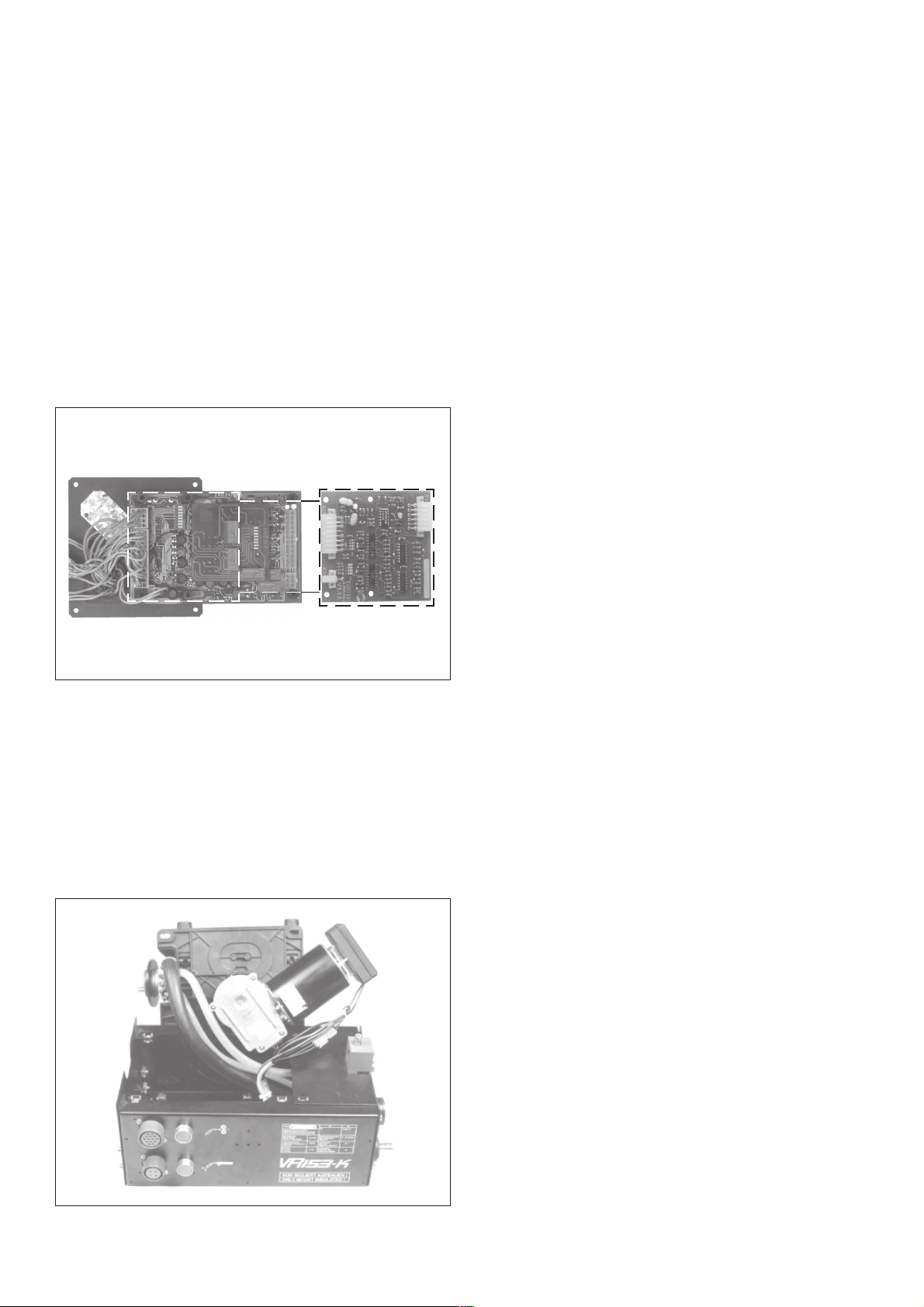
LEDs ON THE FRONT PANEL
RECOMMENDED SERVICE JOBS
MAINS LED
This green LED lights up when the mains supply voltages are
present and the machine is switched on.
OVERVOLTAGE LED
This red LED lights up if the mains voltage deviates by more than
+/-10 % from the standard value.
OVERTEMP. LED
This red LED lights up if there is a fault in the cooling system or if
the duty cycle of the machine is exceeded.
CHANGING THE LIDE-IN MODULE: Fig. 13
- switch off the machine at the master switch
- unplug the robot control unit
- remove the cover plate from the rear
- undo the plug-in connections
ONCE A WEEK
- Coolant (if applicable)
- condition of welding torch
- wire infeed and wire transport system
ONCE A YEAR
- blast clean the wirefeed unit with dry compressed air
- check all mechanical parts
- motor-speed adjusting range
- general checks
- check the gas filter (only with option gas monitor)
Fig. 13
REMOVING THE MOTOR BASEPLATE: Fig. 14
- switch off the machine at the master switch
- undo the 4 fixing screws on the motor basplate
- first lift the motor basplate at the central connector, then turn it
slightly to the left
- unplug the actual-value pick-up
Fig. 14
18
Page 37

MODE D’EMPLOI
FRANÇAIS
1
Page 38

2
Page 39

CHER CLIENT DE FRONIUS,
La présente brochure est destinée à vous familiariser avec la
commande et l‘entretien de la Roboterinterface TSST 153. Lisez
attentivement le mode d‘emploi et observez scrupuleusement les
instructions. Vous éviterez ainsi des pannes dues à de fausses
manoeuvres. Vous en serez récompensé par la fiabilité de
fonctionnement et la longue durée de vie de votre appareil.
FRONIUS SCHWEISSMASCHINEN
VERTRIEB GMBH & COKG
Attention ! Seules des personnes qualifiées sont autorisées à effectuer la mise en service de l‘appareil et ceci
uniquement dans le cadre de la réglementation technique.
Lisez attentivement le chapitre „Consignes de sécurité“
avant de procéder à la mise en service.
SOMMAIRE
Cher client de Fronius,.................................................................................... 3
Consignes de sécurité .................................................................................... 4
Schéma de principe fondamental ....................................................................6
Description des éléments de commande ........................................................7
Caractéristiques techniques ............................................................................8
Scheme des connexions d’interface............................................................... 9
Scheme des connexions ............................................................................. 10
Description générale d’interface ..................................................................... 11
plaquette à circuits imprimés IROZU ............................................................ 11
Explications des signaux de commande vers le robot ................................ 11
Explication des signaux de commande vers la source de courant............ 12
Valeurs théoriques ........................................................................................ 12
Interface robot numérique ............................................................................. 13
Sortie des paramètres de soudage et des tensions d’alimentation ............. 14
Raccord et mise en service de la source de courant robot ........................ 14
Adaptation d’une TS ou TPS pour service à robot...................................... 15
Fonction des sous-groupes .......................................................................... 15
Check-list DEL NMI 4D .............................................................................. 16
Contrôle par DEL sur l’interface et détection de défauts ............................. 17
Travaux de service recommandés.............................................................. 18
Liste de pièces de rechange ........................................................................ 53
Schema de connexions ................................................................................ 53
Fronius - Bureaux de vente et bureaux de service.................................... 53
FRANÇAIS
3
Page 40

CONSIGNES DE SÉCURITÉ
GÉNÉRALITÉS
La soudeuse répond aux derniers développements techniques et satisfait à la réglementation généralement reconnue en matière de sécurité.
En cas de fausse manoeuvre ou de mauvaise utilisation, elle présente
toutefois certains risques
- pour la santé et la vie de l‘utilisateur ou d‘un tiers,
- pour l‘appareil et pour d‘autres biens matériels de l‘exploitant,
- liés à la qualité du travail effectué avec la soudeuse.
Toutes les personnes intervenant dans la mise en service, la manipulation et l‘entretien de la soudeuse doivent
- avoir la qualification requise,
- avoir des connaissances suffisantes en soudure et
- observer scrupuleusement les instructions de service.
Tout dérangement susceptible d‘affecter la sécurité doit être réparé sans
délai.
Votre sécurité est en jeu !
UILISATION CONFORME
La soudeuse a été conçue exclusivement pour une utilisation de le cadre
des travaux prévus (voir chapitre „Mise en service de l’appareil de
soudage“).
L‘utilisation conforme implique également l‘observation
- de toutes les consignes figurant dans les instructions de service
- des travaux d‘inspection et d‘entretien prescrits.
OBLIGATIONS DE L‘EXPLOITANT
L‘exploitant s‘engage à n‘autoriser l‘utilisation de la soudeuse qu‘à des
personnes
- connaissant les prescriptions fondamentales concernant la sécurité
du travail et la prévention d‘accidents et familiarisées avec la manipulation de la soudeuse
- ayant lu et compris les avertissements figurant dans ces instructions
de service, et l‘ayant confirmé en apposant leur signature.
L‘exploitant est tenu de contrôler régulièrement si le personnel travaille
en respectant les prescriptions en matière de sécurité.
OBLIGATIONS DU PERSONNEL
Toutes les personnes chargées de travailler avec la soudeuse s‘engagent à
- respecter les prescriptions fondamentales en matière de sécurité du
travail et de prévention des accidents,
- à lire le chapitre concernant la sécurité ainsi que les avertissements
figurant dans les présentes instructions de service et à attester par
leur signature qu‘ils les ont compris, ceci avant d‘entamer le travail.
EQUIPEMENT DE PROTECTION INDIVIDUEL
Prenez les dispositions suivantes pour préserver votre sécurité :
- portez des chaussures solides, isolantes. Ces chaussures doivent
rester isolantes même dans un environnement humide
- protégez les mains par des gants isolants
- protégez les yeux des rayons ultraviolets en utilisant un écran de
soudeur doté de verres filtrants réglementaires
- portez uniquement des vêtements appropriés (difficilement inflammables)
- en cas de production importante de bruit, portez un casque antibruit
Toutes les personnes se trouvant dans le voisinage de l‘arc électrique
doivent
- être informées des dangers
- équipées des moyens de protection adéquats ;
- si nécessaire, prévoir des cloisons ou tentures de protection.
RISQUE PROVENANT DU DÉGAGEMENT DE
VAPEURS ET GAZ DE NOCIFS
- Prévoir un système d‘aspiration adéquat pour évacuer les fumées et
gaz nocifs de la zone de travail.
- Veiller à une ventilation suffisante.
- Eviter que les vapeurs dégagées par des solvants pénétrent dans la
zone de rayonnement de l‘arc électrique.
RISQUES PROVENANT DE LA PROJECTION
D‘ÉTINCELLES
- Eloigner tout objet inflammable de la zone de travail.
- Il est interdit de souder sur des réservoirs contenant ou ayant contenu
des gaz, des carburants, des huiles minérales et substances analogues. Même des résidus de ces substances présentent un risque
d‘explosion.
- Dans les locaux exposés au risque d‘incendie ou d‘explosion, une
réglementation particulière est applicable. Respecter la réglementation nationale et internationale qui s‘y rapporte.
RISQUES PROVENANT DU COURANT SECTEUR ET
DU COURANT DE SOUDAGE
- Une décharge électrique peut avoir des conséquences graves. En
principe, toute décharge peut être mortelle.
- Les champs magnétiques générés par de fortes intensités de courant
peuvent affecter le fonctionnement d‘appareils électroniques vitaux
(par exemple, stimulateurs cardiaques). Les personnes porteuses
d‘appareils de ce genre devraient consulter leur médecin avant de se
tenir à proximité immédiate d‘une zone de soudage.
- Tous les câbles de soudage doivent être bien fixés, intacts et isolés.
Remplacer immédiatement tout raccord lâche ou câble brûlé.
- Faire vérifier régulièrement par un électricien professionnel le conducteur de terre de la ligne d‘alimentation secteur et la ligne
d‘alimentation de l‘appareil.
- Avant d‘ouvrir l‘appareil à souder, s‘assurer qu‘il ne puisse pas être
accidentellement rebranché. Décharger les composants susceptibles d‘être électriquement chargés.
- Au cas où des interventions sur des éléments sous tension seraient
nécessaires, il est indispensable de faire appel à une seconde
personne qui puisse, le cas échéant, couper l‘alimentation électrique.
ZONES PARTICULIÈREMENT DANGEREUSES
- Ne jamais approcher les doigts des roues dentées du système
d‘entraînement du fil lorsqu‘il est en fonctionnement.
- Dans les locaux exposés au risque d‘incendie ou d‘explosion, une
réglementation particulière est applicable. Respecter la réglementation nationale et internationale qui s‘y rapporte.
- Les soudeuses destinées aux travaux dans des locaux à risques
électriques accrus (p. ex. chaudières) doivent être pourvus du label
S (Safety).
- Les soudures exigeant des mesures de sécurité particulières doivent
obligatoirement être réalisées par des soudeurs ayant reçu la formation adéquate.
4
Page 41

- Lors du transport par grue de la source de courant, toujours accrocher
les chaînes ou les câbles dans les anneaux de levage en gardant un
angle le plus perpendiculaire possible. Retirer la bouteille de gaz et
l‘unité d‘entraînement du fil.
- Lors du transport par grue de l‘unité d‘entraînement du fil, toujours
utiliser une suspension isolante.
MESURES DE SÉCURITÉ RELATIVES À
L‘INFORMATION
- Les instructions de service doivent être conservées en permanence
sur le lieu d‘utilisation de la soudeuse.
- En complément aux instructions de service, la réglementation généralement valable et la réglementation locale concernant la prévention d‘accidents et la protection de l‘environnement doivent à tout
moment être disponibles et respectés.
- Toutes les consignes de sécurité et les avertissements de danger
apposés sur la soudeuse doivent rester lisibles.
MESURES DE SÉCURITÉ SUR LE LIEU
D‘INSTALLATION DE LA SOUDEUSE
- Le poste à souder doit être installé sur un sol ferme et plat offrant
suffisamment de stabilité. Le renversement de la soudeuse présente
un grave danger !
- Dans les locaux exposés au risque d‘incendie ou d‘explosion, une
réglementation particulière est applicable. Respecter la réglementation nationale et internationale qui s‘y rapporte.
- Assurer par des directives et des contrôles internes que l‘environnement du lieu de travail soit toujours propre et ordonné.
COURANTS DE SOUDAGE VAGABONDS
- Veiller à une liaison solide de la pince à pièces usinées avec la pièce
usinée
- Lorsque le fond est conducteur électriquement, mise en place, si
possible, de l’appareil de soudage de sorte à l’isoler
En cas d’inobservation, des courants de soudage vagabonds surviennent pouvant conduire à la destruction de conducteurs de protection, de
l’appareil de soudage et d’autres installations électriques.
MESURES DE SÉCURITÉ EN FONCTIONNEMENT
NORMAL
- N‘utiliser la soudeuse que si tous les dispositifs de sécurité fonctionnent.
- Avant la mise en circuit de l‘appareil, s‘assurer que personne ne peut
être mis en danger.
- Au moins une fois par semaine, vérifier si la soudeuse ne présente
aucune détérioration détectable de l‘extérieur et contrôler le
fonctionnement des dispositifs de sécurité.
- VBG 4, §5 - Installations électriques et matériel électrique
- VBG 15, §33 / §49 - Soudure, découpage et opérations analogues
- VDE 0701-1 - Réparation, modification et contrôle d‘appareils électriques; exigences générales
- VDE 0702-1 - Essais de répétition sur les appareils électriques
Pour des renseignements plus précis concernant la mise en service, la
modification et l‘essai de postes de soudage, veuillez demander
l‘instruction de travail „Inspection de sécurité d‘appareils de soudage“
(AA-PMÜ-01) à votre poste de service Fronius.
MODIFICATIONS APPORTÉES À LA SOUDEUSE
- Aucune modification, transformation ou montage ne peuvent être
effectués sur la soudeuse sans l‘autorisation du constructeur.
- Remplacer immédiatement tout composant présentant un défaut
quelconque.
PIÈCES DE RECHANGE ET PIÈCES D‘USURE
- N‘utiliser que des pièces de rechange ou des pièces d‘usure d‘origine.
Les pièces d‘autres fabricants n‘offrent pas les garanties de sécurité
et de fonctionnement suffisantes.
- Pour toute commande, prière d‘indiquer la dénomination et le numéro
de référence exacts, comme indiqués sur la liste des pièces de
rechange, ainsi que le numéro de série de l‘appareil.
ETALONNAGE DE POSTES À SOUDER
Les normes internationales préconisent l‘étalonnage à intervalle régulier
des postes à souder. Fronius recommande d‘effectuer cet étalonnage
tous les 12 mois. Si vous désirez de plus amples informations à ce sujet,
n‘hésitez pas à contacter votre concessionnaire Fronius !
LABEL CE
La soudeuse satisfait aux exigences fondamentales de la directive en
matière de basse tension et de compatibilité électromagnétique et a
obtenu le label CE.
DROITS D‘AUTEUR
La société Fronius International GmbH&Co.KG est propriétaire des
droits d‘auteurs sur ces instructions de service.
Le texte et les figures correspondent à l‘état de la technique au moment
de la mise sous presse. Sous réserve de modification. Le contenu des
présentes instructions de service ne fondent aucun recours de la part de
l‘acheteur. Nous sommes reconnaissants pour toute proposition
d‘amélioration ou indication d‘erreurs figurant dans les instructions de
service.
CONTRÔLE DE SÉCURITÉ
Après toute modification, réparation, ou entretien de la soudeuse et au
moins une fois tous les douze mois, l‘exploitant est tenu de faire effectuer
un contrôle de état par un électricien professionnel.
Pour la vérification, tenir compte des prescriptions suivantes :
- IEC (EN) 60 974-1 - Matériel de soudage électrique - Partie 1:
Sources de courant pour soudage
FRANÇAIS
5
ud_fr_st_sv_00147 012001
Page 42
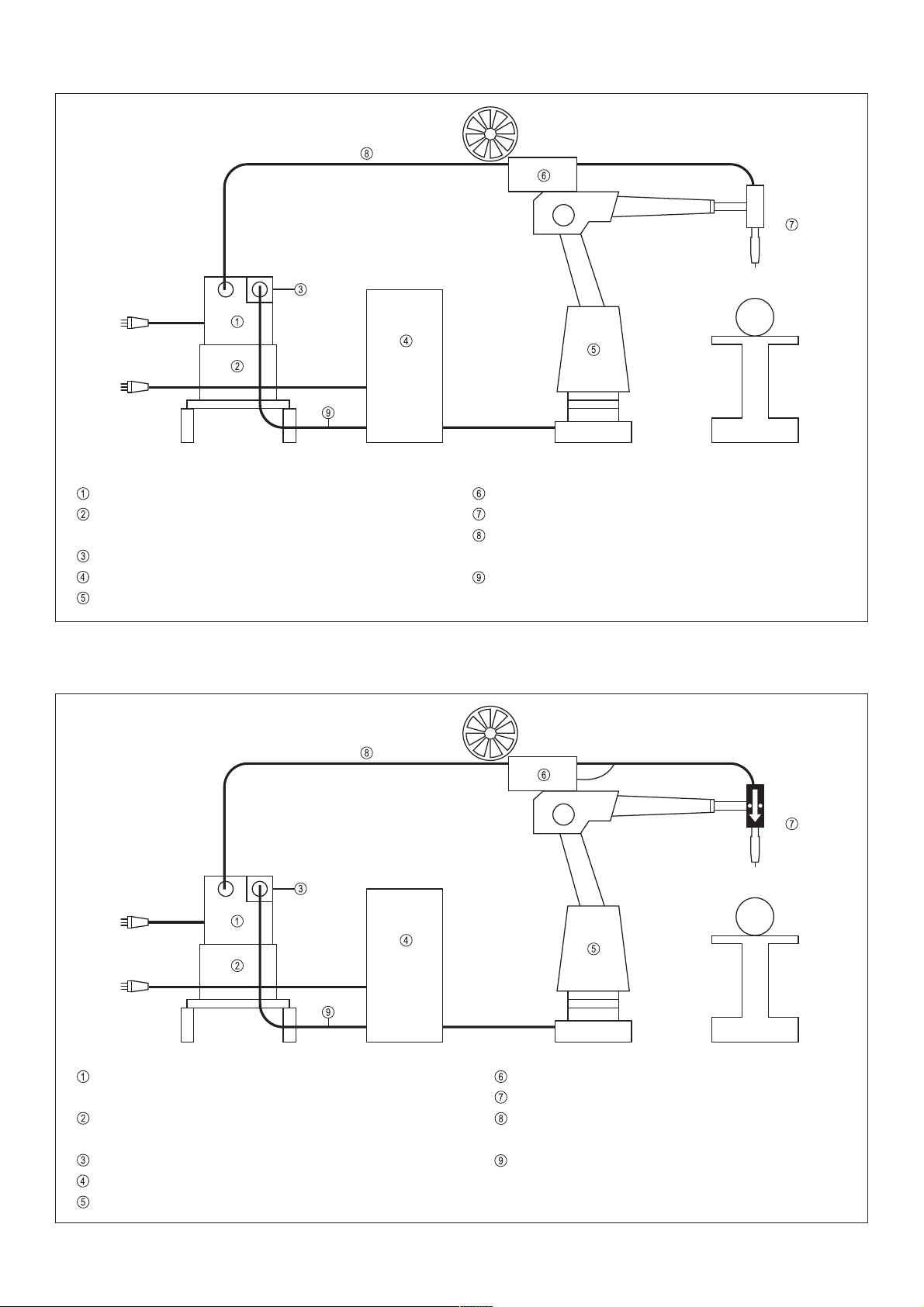
SCHÉMA DE PRINCIPE FONDAMENTAL
SOURCE DE COURANT TS / TPS
CIRCUIT DE REFROIDISSEMENT FK 71
avec contrôleur d’eau
INTERFACE DE ROBOT
COMMAND DE ROBOT
ROBOT
Fig. 1 Modèle standard
VR 153-K avec contrôleur de gaz réglable
TORCHE-MACHINE
FAISCEAU DE CÂBLES INTERMÉDIAIRE 4m / 8m
(possibilité de longueurs spéciales)
CÂBLE DE CONNEXION DE ROBOT
SOURCE DE COURANT avec régulateur Push-Pull
incorporé TS / TPS
CIRCUIT DE REFROIDISSEMENT FK 71
avec contrôleur d’eau
INTERFACE DE ROBOT
COMMAND DE ROBOT
ROBOT
Fig. 2 Modèle avec torche Push-Pull
VR 153-K avec contrôleur de gaz réglable
TORCHE PUSH-PULL
FAISCEAU DE CÂBLES INTERMÉDIAIRE 4m / 8m
(possibilité de longueurs spéciales)
CÂBLE DE CONNEXION DE ROBOT
6
Page 43

DESCRIPTION DES ÉLÉMENTS DE COMMANDE
Les éléments de commande de la source de courant nous vous prions de consulter les instructions de service de la source de courant
correspondante.
Fig. 3
PLAQUE DE MOTEUR
Un moteur d’avance spécial à nombre de tours réglé assure
desvitesses d’avance de fil exactes
RACCORD CENTRAL DE LA TORCHE
Fronius, Dinse, Binzel
RACCORD À FICHES DE LA CONDUITE D’ALLER D’EAU
Seulement avec Dinse et Binzel: raccord central
RACCORD À FICHES DE LA CONDUITE DE RETOUR D’EAU
Seulement avec Dinse et Binzel: raccord central
DOUILLE DE RACCORD DE LA COMMANDE PUSH-PULL
(Amphénol à 14 broches)
Ici on raccorde la fiche de commande de la torche Push-Pull.
De même on peut brancher ici une touche de vérification de
gaz externe, une touche d’introduction de fil ainsi que quatre
signaux vers le robot. Raccord libre (Amphénol à 4 broches).
TOUCHE D’INTRODUCTION DE FIL
Lors de l’activation de cette touche, le fil de soudage est
introduit sans gaz et sans courant dans le faisceau de câbles
de la torche.
Touche de vérification de gaz
Lors de l’activation de cette touche on peut régler ou mesurer
sur le détendeur de gaz la quantité de gaz requise.
DOUILLE DE RACCORD POUR SIGNAUX DE COMMANDE
Raccord CPC à 37 broches vers la source de courant.
RACCORD DE COURANT DE SOUDAGE
Avec des faisceaux de câble plus longs que 8 m il faut
raccorder ici une pièce de distribution (utiliser 2 câbles de
courant parallèles) -> potentiel de soudage positif
RACCORD D’EAU
Conduite d’aller d’eau du groupe de refroidissement
RACCORD D’EAU
Conduite de retour d’eau vers le groupe de refroidissement
RACCORD DE GAZ DE PROTECTION
Ici le filtre à gaz est vissé
VIS DE RÉGLAGE DU CONTRÔLEUR DE GAZ (option)
Avec cette vis de réglage on peut régler la quantité de gaz de
réaction de la reconnaissance de manque de gaz. Voir chapitre «Raccord de mise en service de la source courant robot».
DOUILLE DE RACCORD DE ROBOT
CPC à 37 broches; Pour la commande de robot voir chapitre
«Schéma des connexions».
Fig. 4
POTENTIOMÈTRE DE RÉGLAGE DE LA PÉRIODE DE
POST-COMBUSTION
Est utilisé seulement quand le robot n’émet aucune valeur
théorique de la période de post-combustion. Au moment de la
termination du processus de soudage un circuit électronique
spécial déconnecte d’abord le moteur d’avance et ensuite
déconnecte à retard le courant de soudage. Ainsi on évite la
fusion du bout de fil sur le métal de soudage refroidi!
Réglage voir chapitre «Valeurs théoriques»
POTENTIOMÈTRE DE RÉGLAGE DE LA CORRECTION DU
DÉTACHEMENT DE GOUTTES
Est utilisé seulement avec TPS en mode de fonctionnement
pulsé, quand le robot n’émet pas de valeur théorique correspondante. La correction du détachement de gouttes permet
de modifier le courant de détachement de gouttes.
VOYANT DE CONTRÔLE DEL
Pour la reconnaissance de défauts. Voir chapitre ”Check-list
DEL NMI4D“
TOUCHE DE VÉRIFICATION DE GAZ même fonction que
pos.
DOUILLE DE RACCORD D’AVANCES DE FIL
En plus de l’avance à robot VR 153-K on peut raccorder ici
aussi toutes les avances standards pour le service de soudage
à la main
RACCORD DE COURANT
Potentiel positif pour l’avance
ALIMENTATION DU CIRCUIT DE REFROIDISSEMENT
Le soudage est possible seulement avec circuit de refroidissement branché.
FRANÇAIS
Fig. 5
7
Page 44

CARACTÉRISTIQUES TECHNIQUES
VR 153-K
Type de protection IP 23
Vitesse d’avance de fil 0 – 22 m/min;
démultiplication 24,5 : 1
Galets d’avance de fil Ø 0,8 – 3,2 mm
Poids 6,4 kg
Dimensions (longueur x largeur x hauteur) 370 x 210 x 195
Facteur de service (sans torche) 500 A, 60 %
Contrôleur de débit de gaz
réglable sans intervalles de 0 – 20 l/min
Vanne magnétique à gaz 42 V CA
Fixation:
Attention! Doit être établie de manière isolée par rapport
à la terre. Fixation d’en bas par vis d’isolation.
MOTEUR À AIMANTS PERMANENTS (STANSARD)
Puissance nominale 160 W
Induit 42 V CC / 3,25 A
Nombre de tours nominal 6600 trs/min.
Puissance utile 80 W
Réglage optoélectronique du nombre de tours
VR 153-K T.I.M.E.
Type de protection IP 23
Vitesse d’avance de fil 0 – 30 m/min;
démultiplication 17,6 : 1
Galets d’avance de fil Ø 0,8 – 3,2 mm
Poids 6,4 kg
Dimensions (longueur x largeur x hauteur) 370 x 210 x 195
Facteur de service (sans torche) 500 A, 60 %
Contrôleur de débit de gaz
réglable sans intervalles de 0 – 20 l/min
Vanne magnétique à gaz 42 V CA
Fixation:
Attention! Doit être établie de manière isolée par rapport
à la terre. Fixation d’en bas par vis d’isolation. L’option d’un
entrefer plat doit être installée dans l’appareil de soudage.
MOTOR À ENTREFER PLAT
Puissance nominale 117,8 W
Alimentation 42 V CC / 4,2 A
Réglage optoelectronique du nombre de tours
MOTEUR PUSH-PULL
Excitation permanente
Induit 42 V CC / 0,9 A
I X R Réglage avec définition de valeur théorique et déconnexion
par surcharge
8
Page 45
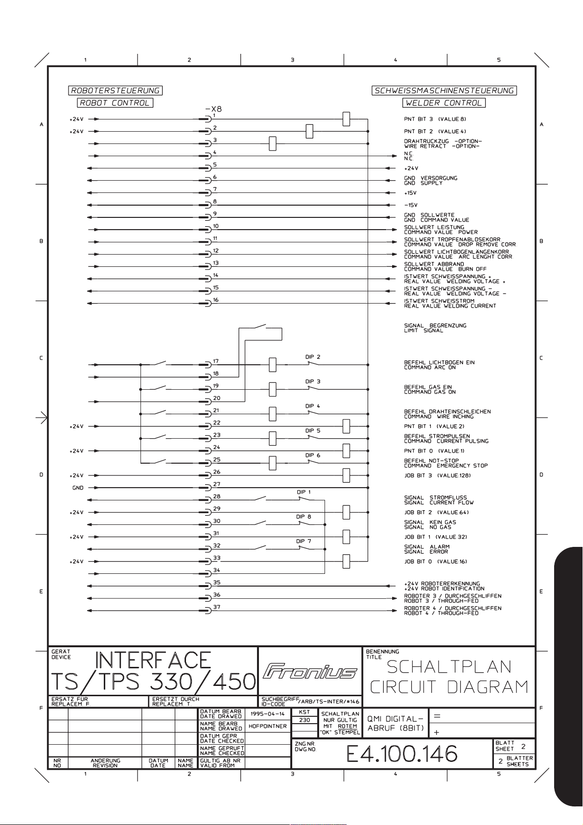
SCHEME DES CONNEXIONS D’INTERFACE
FRANÇAIS
9
Page 46
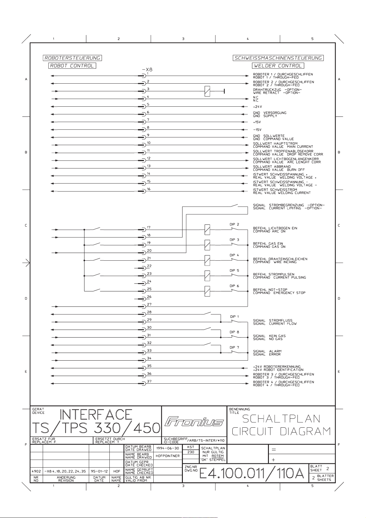
SCHEME DES CONNEXIONS
10
Page 47

DESCRIPTION GÉNÉRALE D’INTERFACE
PLAQUETTE À CIRCUITS IMPRIMÉS IROZU
En principe les fonctions peuvent être réglées sur la source de
courant par un signal de 24 V C.C. (+/- 10%) 0,1 A (approprié pour
sorties de relais et transistor).
En cas de sorties de relais on peut utiliser l’alimentation de 24 V
C.C. de la TS ST153.
Pour la commande des paramètres de soudage on a besoin d’au
moins deux tensions de contrôle analogues de 0 - 10 V C.C. 5 mA.
En cas de perturbations ces lignes devraient être blindées.
La séparation du robot et de la source de courant est réalisée
moyennant relais dans la TS ST 153 (excepté les signaux de
commande analogiques, la valeur effective de courant et la valeur
effective de tension)
Caractéristiques techniques:
Tension nominale de bobine 24 V CC
Résistance de bobine 1200 ohms
Temps de rebondissement 2 ms
Temps de réaction 8 ms
Temps de décollage 3 ms
La diode de roue libre est incorporée.
La connexion entre le robot et la source de courant est réalisée par
une connexion à 37 broches sur la TS ST 153. Le câble d’union
ne devrait pas dépasser la longueur de 10 m.
L’»état» des signaux d’entrée et de sortie ainsi que les alimentations de courant et les valeurs théoriques peuvent être vérifiées
moyennant des diodes électroluminescentes sur le dos de la
source de courant.
a) ARC ON - indique le démarrage d’arc électrique du robot
GAS ON - indique la vérification de gaz du robot
INCHING - indique l’instruction d’introduction de fil du robot
PULS ON - indique le service pulsé (seulement avec TPS)
b) PULS CORR. ...... Correction de détachement de gouttes
(seulement avec TPS)
VOLT CORR. ......Correction de tension de l’arc électrique
POWER .............. Puissance
BURN BACK .......Période de post-combustion
1
1
1
1
c) +10 V, +24 V, -15 V, +15 V
indique, si les tensions d’alimentation sont actives
d) NO GAS2 (voir chapitre suivante)
ERROR2 (voir chapitre suivante)
EMERGENCY STOP2 (voir chapitre „Explication des signaux
de commande vers la source de courant“.)
1
indiquent les valeurs théoriques 0-10V du robot avec min.
(0V) DEL sombre, avec max. (10V) DEL allumée.
2
Allumée en cas de signal de défaut de la source de courant
La plaquette à circuits imprimés IROZU permet une sélection
simplifiée des signaux (high/low) moyennant huit commutateurs
DIP (occupation des commutateurs DIP voir table)
Commutateur DIP high low
1 .......... Error off on
2 .......... Error on off
3 .......... Emergency-Stop off on
4 .......... Emergency-Stop on off
5 .......... Emergency-Stop LED off on
6 .......... Emergency-Stop LED on off
7 .......... No Gas off on
8 .......... No Gas on off
EXPLICATIONS DES SIGNAUX DE
COMMANDE VERS LE ROBOT
Tous les signaux de commande vers le robot sont produits par des
contacts de relais. Toujours les deux occupations de contact du
contact de travail sont installées. Il ne faudrait pas connecter une
tension plus élevée que 24 V - le courant de commutation ne
devrait pas dépasser 0,5 A.
La ligne de retour commune de ces signaux de commande est
*--* PIN 34, quand les commutateurs DIP 1, 7 et 8 sont connectés.
Ces commutateurs DIP ont été livrés en état connecté (ON).
SIGNAL DE «CONDUCTION DE COURANT»
SORTIE PIN 28 ET 29 (34)
Ce signal est produit par un contact de travail. Celui-ci ferme après
que le courant de départ de la source de courant commence à
circuler. Il ouvre en cas d’interruption du courant de soudage
après une temporisation d’environ 0,15 sec.
SIGNAL «ERROR»
SORTIE PIN 32 ET 33 (34)
Le commutateur DIP 1 et le commutateur Dip 2 permettent de
sélectionner le signal “ERREUR” sur la plaquette à circuits imprimée additionnelle en tant que contact de repos ou contact de
travail. Le signal surveille toutes les fonctions défectueuses et
remet la source de courant à la valeur initiale. Á savoir le soudage
ne peut être recommancé qu’après avoir éliminé l’erreur et donné
une nouvelle commande de démarrage.
La modification d’état du contact peut être provoquée par les
suivantes fonctions défectueuses sur la source de courant:
a) Température trop élevée: quand le facteur de service est
dépassé ou en cas de défaut dans le système de refroidissement après une temporisation d’environ 5 sec.
b) Tension trop élevée/trop basse: en cas de déviations de la
tension de réseau de +/-10% (à partir de 1991)
c) Remise à zéro du moteur: avec courant de moteur trop élevé
ou remise à zéro push-pull par courant trop élevé
d) No Program: en cas de réglage erroné du sélecteur de
programme (seulement avec TS 330)
e) Power on Reset: après la mise en circuit de la source de
courant pendant 2 sec.
f) Remise à zéro du robot: en cas d’une instruction d’arrêt
d’urgence du robot ou en cas de manque de gaz.
FRANÇAIS
11
Page 48

SIGNAL «PAS DE GAZ» (seulement optionnellement en fonction)
SORTIE PIN 30 ET 31 (34)
Le commutateur DIP 7 et le commutateur DIP 8 permettent de
sélectionner le signal “PAS DE GAZ” sur la plaquette à circuits
imprimés additionnelle en tant que contact de repos ou contact
de travail. L’état du contact est changé, quand le transmetteur de
débit dans VR 153-K annonce un débit de gaz trop faible pendant
le soudage. Le retard à l’armement s’élève à environ 1 sec.
Ce signal provoque une remise à zéro automatique de la source
de courant et il est indiqué aussi comme signal d’erreur collectif
(voir chapitre antérieur).
Note: Après la mise en circuit de la source de courant la pression
de gaz est augmentée jusqu’à ce que le débit de passage désiré
(réglée) est obtenue (max. 12 sec. = faisceau de câbles de 8 m).
La surveillance du débit de gaz peut être réglée sur le VR 153-K
de 0 – 20l/min.
SIGNAL DE LA VALEUR LIMITE
(seulement optionnellement en fonction)
SORTIE PIN 18 ET 20
Ce signal est activé seulement en mode de fonctionnement à
point de travail (en connexion avec des systèmes d’assurance de
qualité) lors du dépassement des valeurs limites définies (courant de soudage ou tension de soudage) -> le contact de travail
est sans potentiel.
EXPLICATION DES SIGNAUX DE COMMANDE
VERS LA SOURCE DE COURANT
Tous les signaux de commande du robot doivent être transmis
à 24 V DC. Le conducteur commun des signaux de commande
est PIN 27, quand les commutateurs DIP 2,3,4,5 et 6 sont
connectés. Ces commutateurs DIP sont livrés en état connecté
(ON).
INSTRUCTION «ARC ÉLECTRIQUE MARCHE»
ENTRÉE PIN 17 et 27
Par cette instruction donnée par un contact de travail dans la
commande par robot le processus de soudage est démarré.
Les temps de prédébit et postdébit de gaz peuvent être réglés sur
la plaquette à circuits imprimés de réglage du moteur (NMI 3DO)
dans la source de courant (régulateur-trimmer). De même il est
possible de régler la vitesse d’approche avant l’amorçage en tant
que pourcentage fixe de la valeur théorique. (voir les instructions
de réglage NMI 3DO)
Avec les installations TS 331 et TPS ce réglage peut se faire sur
la plaquette à circuits imprimés SMS après avoir dévissé la
plaquette de la table de programme.
SÉQUENCE:
- ARC ÉLECTRIQUE «MARCHE»: Prédébit de gaz - tension de
marche à vide marche - avance de fil démarrage - courant de
soudage.
- ARC ÉLECTRIQUE «ARRÊT»: Courant de soudage - avance
de fil arrêt - courant de soudage arrêt - postdébit de gaz.
INSTRUCTION GAZ «MARCHE»
ENTRÉE PIN 19 et 27
Cette instruction commande la vanne magnétique à gaz moyennant un contact de travail dans l’interface.
La surveillance de débit de gaz n’est pas en fonction.
INSTRUCTION «INTRODUCTION DE FIL»
ENTRÉE PIN 21 et 27
Cette instruction est donnée par un contact de travail dans la
commande par robot et provoque l’avance de fil manuelle.
La valeur théorique de vitesse dépend du programme de soudage
et de la valeur théorique de puissance.
INSTRUCTION «RETRAITE DE FIL» (OPTION)
ENTRÉE PIN 3 (doit être donnée à +24V DC)
Cette instruction est donnée par un contact de travail dans la
commande par robot et provoque la retraite manuelle du fil.
La valeur théorique du fil est émise par le robot suivant la
puissance théorique. La fonction de cette instruction est assurée
seulement, quand aucune instruction de démarrage à arc électrique ou d’introduction de fil n’est donnée et quand l’OPTION de
retraite de fil est installée.
IMPULSION / STANDARD COMMUTATION
ENTRÉE PIN 23 ET 27
Cette instruction provoque une commutation du programme
standard au programme de soudage par impulsion (seulement
utilisé avec TPS). Avec la TS 330/331 ce signal ne provoque pas
de changement. Il est toutefois nécessaire que les programmes
de soudage par impulsion et les programmes standards du
matériau correspondant existent dans l’Eprom.
INSTRUCTION «ARRÊT D’URGENCE» (service à bouton)
ENTRÉE PIN 25 et 27
Le commutateur DIP 3 et le commutateur DIP 4 permettent de
sélectionner sur la plaquette à circuits imprimés additionelle, si
pendant le soudage il faut appliquer de la tension sur pin 25 et
pin 27 (High ou Low actif). Les commutateurs DIP 5 et 6 qui se
trouvent à côté permettent de commuter les DELs d’ARRÊT
D’URGENCE!
Cette instruction provoque une remise à zéro immédiate de la
source de courant déjà lors d’un message d’erreur de courte
durée. On peut continuer le soudage seulement après avoir
donné une nouvelle instruction de démarrage.
COMMANDE D’«EXTINCTION» (OPTION)
Entrée broche 3 et broche 4 (devant être excitée par +24 V CC)
Attention! on ne pourra utiliser que l’option “extraction de
fil” ou l’option “extinction”!
Les deux broches sont directement câblées vers la fiche CPC à
37 pôles, à laquelle est raccordé le dispositif d’avance.
broche 3 é broche 17 (+24 V CC)
broche 4 é broche 18 (terre)
L’effet de cette commande est d’éteindre le chalumeau au moyen
d’air comprimé. La commande ne peut fonctionner que si cette
option a été prévue.
VALEURS THÉORIQUES
Toutes les valeurs théoriques sont réalisées par une tension CC
de 0 – 10 V/5mA. Le point de référence est GND pour les valeurs
théoriques (PIN 9).
Temporisation....15 ms.
TENSION PILOTE POUR «CORRECTION DE LONGUEUR DE L’ARC
ÉLECTRIQUE» ENTRÉE PIN 12
Cette tension pilote permet de corriger la longueur de l’arc
électrique. On modifie seulement la tension de l’arc électrique,
mais non la vitesse d’avance de fil.
0 V = tension de l’arc électrique - 20% (arc électrique plus court)
5 V = 0% (valeur mémorisée)
10 V = Tension de l’arc électrique + 20% (arc électrique plus
long)
12
Page 49

TENSION PILOTE POUR «PUISSANCE DE SOUDAGE»
ENTRÉE PIN 10
La puissance de soudage dépend de la valeur théorique et du
programme.
p.ex. 0 V = 50 A (courant de soudage min. pour le fil utilisé)
5 V = 100 A
10 V = 200 A (courant de soudage max. pour le fil utilisé)
Les réglages de base suivant le fil utilisé doivent être faits sur la
source de courant.
Attention! Quand il y a une interface robot numérique dans
la source de courant il faut assurer que le robot soit équipé
des sorties numériques requises! Quand on branche ici
une carte analogique il y a le danger qu’elle soit détruite.
Lors du remplacement de la source de courant il faut alors
veiller à ce que dans la source de courant de remplacement on utilise une interface de la même configuration.
SIGNAL “CORDON-BIT 0”, valeur 1
Pin 24 et 27
TENSION PILOTE POUR
«PÉRIODE DE POST-COMBUSTION»
ENTRÉE PIN 13
Cette valeur théorique permet de déterminer la longueur de fil
libre après le soudage. Plus la période de post-combustion est
réduite, plus la longueur de fil libre sera longue.
TS 330 TPS/TS
0 V = 0 sec. 0 V = 200 ms
5 V = 0,15 sec 5 V = 0% valeur programmée
10 V = 0,3 sec 10 V = +200 ms
Quand ce PIN n’est pas connecté, on peut régler la valeur automatiquement sur l’interface de robot.
TENSION PILOTE POUR «CORRECTION D’IMPULSION»
ENTRÉE PIN 11 - (seulement avec TPS)
0 V ... correction d’impulsion minimale
5 V ... correction d’impulsion normale
10 V ... correction d’impulsion maximale
Quand ce PIN n’est pas connecté, on peut régler la valeur
automatiquement sur l’interface de robot.
INTERFACE ROBOT NUMÉRIQUE
L’interface robot numérique est requise, quand:
- on a besoin des fonctions Q-Master,
- le robot n’a plus de canaux analogiques à sa disposition
- on ne doit plus changer des points de travail, parce qu’ils ont
déjà été optimisés pour un cordon de soudure et ces réglages
ne sont pas appropriés pour toutes les tâches de soudage,
- on doit travailler alternativement avec différentes programmes
de soudage sans modification sur la machine,
- on travaille avec différentes valeurs limites (courant, tension)
(p.ex. Q-Master),
- des documentations sont requise seulement pour certains
cordons de soudure,
- on a besoin de paramètres différents du cratère de démarrage
et du cratère final (courant de dèmarrage, courant final, temps
de démarrage, temps de courant final).
SIGNAL “CORDON-BIT 1”, valeur 2
Pin 22 et 27
SIGNAL “CORDON-BIT 2”, valeur 4
Pin 2 et 27,
SIGNAL “CORDON-BIT 3”, valeur 8
Pin 1 et 27
SIGNAL “JOB-BIT 0”, valeur 16
Pin 33 et 27
SIGNAL “JOB-BIT 1”, valeur 32
Pin 31 et 27
SIGNAL “JOB-BIT 2”, valeur 64
Pin 29 et 27
SIGNAL “JOB-BIT 3”, valeur 128
Pin 26 et 27
Par exemple quand on applique une tension de 24 V CC du robot
à pin 2, pin 33 et pin 26, on sélectionne job 9 et cordon 4 (1 est
toujours job 0 ou cordon 0)
Comme il y a seulement un maximum de 10 jobs et dans chaque
job un maximum de 16 cordons, ce qui donne 160 points de
travail. Pour plus de détails nous vous prions de consulter les
instructions de service de Q-Master et le LCD.
Les deux entrées de valeurs théoriques “puissance pin 10” et
“correction de longueur de l’arc pin 12” peuvent être utilisées pour
la correction analogique! Cette fonction doit être sélectionées
dans le service d’appel! (seulement possible avec Q-Master)!
Par rapport à l’interface analogique l’interface numérique tient
huit entrées supplémentaires. Celles-ci permettent l’appel de
jobs et de cordons. La condition de base de cette fonction est
l’utilisation d’un tiroir LCD. L’activation du Q-Master fait cet appel
beaucoup plus confortable et ainsi est utile.
Remarque! Sur l’interface pin 1 et pin 2 sont éliminés en tant que
lignes, puisqu’ils sont requis pour la sélection du cordon de
soudure.
FRANÇAIS
13
Page 50

SORTIE DES PARAMÈTRES DE SOUDAGE ET
DES TENSIONS D’ALIMENTATION
RACCORD ET MISE EN SERVICE DE LA SOURCE
DE COURANT ROBOT
VALEUR EFFECTIVE DU COURANT DE SOUDAGE
SORTIE PIN 16
Ici on peut surveiller une tension continue isolée électriquement.
Cette tension correspond au courant de soudage 1V = 100 A
(p.ex. pour le système chercheur du cordon de soudure).
Le point de référence de cette tension est PIN 9 (valeurs théo-
riques GND)
VALEUR EFFECTIVE DE LA TENSION DE SOUDAGE
SORTIE PIN 14, 15
Cette tension est directement liée aux douilles de soudage. Ici des
tensions de 0 – 60 V C.C. seront actives pendant le processus de
soudage (p.ex. pour contrôle d’attachement de fil).
ALIMENTATION +15 V
SORTIE PIN 7
Charge de courant maximale 50 mA (protection 125 mA)
(p.ex. pour l’alimentation de la carte de sortie analogique)
ALIMENTATION –15 V
SORTIE PIN 8
Charge de courant maximale 50 mA (protection 125 mA)
ALIMENTATION +24 V
SORTIE PIN 5
Charge de courant maximale 500 mA (protection 630 mA)
(p.ex. pour l’activation des relais sur l’interface)
GND POUR ALIMENTATIONS
SORTIE PIN 6
Retour commun pour les tensions d’alimentation
LIGNES BOUCLÉES vers VR 153-K (raccord push-pull)
SORTIES ou ENTRÉES 1,2,36,37
Charge de courant maximale: lignes 1 et 2 500 mA / 24 V
(Les lignes 1 et 2 sont disponibles seulement avec interface analogique)
lignes 36 et 37 1 A / 42 V
Ici on peut raccorder divers signaux de la torche vers la commande par robot et vice versa.
- Monter l’appareil d’avance VR 153-K de manière isolée sur le
robot - utiliser des vis d’isolation et des plaquettes de Pertinax.
Lors d’un contact du boîtier d’avance avec la pièce à usiner un
«peloton de fil» risque de produire un court-circuit dans l’avance
- soudage du boîtier.
- Raccorder le faisceau de câbles d’union sur l’avance
attacher le collier de fixation sur le bras du robot
- Poser le faisceau de câbles et le raccorder sur la source de
courant
- Raccorder et fixer la torche au raccord central du VR 153-K
- Connecter la ligne de raccord du robot à la borne dans le robot
- Ficher la ligne de raccord du robot
- Régler la source de courant suivant les instructions de service
de l’appareil et la mettre en service.
Après la mise en circuit la DEL de température trop élevée est
allumée pendant quelques secondes, car la colonne d’eau de
refroidissement a besoin d’un certain temps pour s’établir.
- Régler la surveillance de débit de gaz (option)
- dévisser la vis de réglage en tournant vers la gauche
- régler le débit de gaz désiré sur le régulateur de pression
- ouvrir le levier de pression dans le VR 153-K
- donner l’instruction de marche de l’arc électrique et visser
lentement les vis de réglage en tournant à droite jusqu’à ce
que la DEL NO GAS s’allume sur l’interface
- tourner la vis de réglage un tours vers la gauche
- Programmation d’un réglage de base de la carte de sortie
analogique d’un soudage d’essai
CORRECTION D’ARC ÉLECTRIQUE 5 V
PÉRIODE DE POST-COMBUSTION 2 V (avec TPS 5V)
CORRECTION DE DETACHEMENT
DE GOUTTES 5V (seulement TPS)
PUISSANCE suivant l’épaisseur
de matériel 0 - 10V
VITESSE DE SOUDAGE 20 – 50 cm/min.
et
RECONNAISSANCE DE ROBOT
PONT PIN 4 ET PIN 35
(ne pas nécessaire avec nouveaux appareils; à partir du
numéro de série 060000)
(commutation automatique des valeurs théoriques de service
manuel à service par robot, aussitôt que la commande par robot
est connectée)
La commutation dans l’interface se fait, quand ce PIN reçoit +24V
(à savoir pont entre PIN 35 et PIN 4). Avec les nouveaux appareils
ce dispositif est omis.
(«Plaquette à circuits imprimés interface sans relais» voir fig. 9,
pos. ).
Fig. 6 Fig. 7
Pour le principe du procédé MIG/MAG et les mesures de sécurité
voir les instructions de service de la source de courant.
14
Page 51
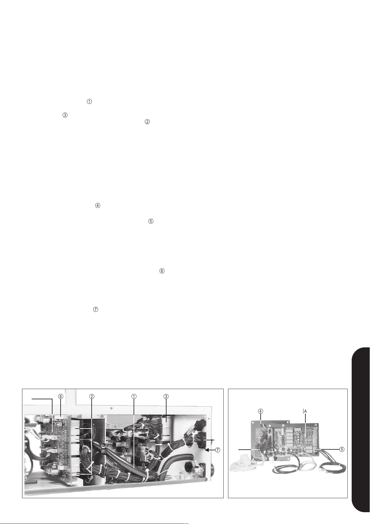
ADAPTATION D’UNE TS OU TPS POUR
SERVICE À ROBOT
- Déconnecter l’appareil, retirer la fiche de réseau
- Enlever l’appareil d’avance et le faisceau de câbles d’union
- Dévisser la couverture d’obturation sur le dos et le couvercle
latéral droit de la source de courant.
- Introduire avec précaution le tiroir de l’extérieur et le fixer par
4 vis à tôle.
- Ficher le câble d’union
à 24 broches et 2 broches sur la plaquette à circuits imprimés
de l’interface
à 14 broches, 6 broches et 2 broches sur NMI
câble à 2 broches de X11 sur le câble à 16 broches sur NMI 4.
- Seulement interface robot: enficher la prise Molex à 24 broches
de la plaquette à circuits imprimés DIGIR sur la plaquette à
circuits imprimés de tiroir SML 4A, barre de prises X11.
- Seulement pour l’option “extinction”: retirer les broches 3+4 de
la prise X11 et enficher à leur place les deux fiches libres du
faisceau de câbles (Attention aux marquages!).
Retirer les broches 17+19 de la prise X9 et enficher à leur place
les deux fiches libres du faisceau de câbles (Attention aux
marquages!).
- Ficher GND sur l’interface
Utiliser à cette fin la ligne GND de la couverture d’obturation
- Ficher le câble d’union vers la fiche d’avance
broches). Ficher les contacts CPC dans la fiche d’avance X9
Ligne 1 => X9 PIN 19
Ligne 2 => X9 PIN 20
Ligne 5 => X9 PIN 36
Ligne 6 => X9 PIN 33
- Enficher le relais STF (connexions des bobines vers le milieu
de la plaquette à circuits imprimés) dans NMI 3DO . Avec
NMI4. le relais est déjà installé.
- Ficher 2 unions de la fiche robot X11 dans la fiche d’avance X9.
Ligne de X11 PIN 36 sur X9 PIN 34.
Ligne de X11 PIN 37 sur X9 PIN 35.
- Ficher le contact aveugle
- Raccorder le VR 153-K avec faisceau de câbles intermédiaire
(voir mise en service)
- Remplacement de FK71 (voir les instructions de service de la
source de courant) ou installation d’un contrôleur de débit, no.
de commande 4.100.025
vers NMI
(fiche à 6
sur la fiche d’avance X9 PIN 37.
FONCTION DES SOUS-GROUPES
SOURCE DE COURANT
- VM 34. Plaquette à circuits imprimés de sécurité
Tensions d’alimentation pour le système électronique
- NMI Plaquette à circuits imprimés de moteur
a) compare la valeur théorique et la valeur effective de la
vitesse de moteur
b) règle le gaz et connecte le courant de soudage de la source
de courant
c) coordonne les différentes séquences de commande
d) possibilité de raccord des régulateurs push-pull
e) alimente le système électronique en tensions continues
stabilisées résistant aux courts-circuits.
- Module thyristor plaquette à circuits imprimés BM 34/45
Vérin de la tension d’induit
- Régulateur du moteur PUSH-PULL PMR 3. (OPTION)
Sert au réglage séparé du moteur push-pull
Différents types: FRONIUS, BINZEL, DINSE
- IRO 34. Plaquette à circuits imprimés d’interface
Établit la connexion entre la source de courant et la commande
par robot.
VR 153-K
- Electrovanne d’air comprimé (seulement si l’option “extinc-
tion” est prévue).
- Contrôleur de débit de gaz
Contrôle le débit de gaz et donne un signal à l’interface, quand
le débit de gaz est plus faible que le débit réglé.
- Vanne magnétique à gaz 42V CA
commande le débit de gaz
- IEGT-C Plaquette à circuits imprimés de transmission de la
valeur effective
Détection de la valeur effective optoélectronique
- Moteur d’entraînement
avec engrenage à vis sans fin 24 : 1
REMPLACEMENT DE LA PLAQUETTE À CIRCUITS IMPRIMÉS NMI ou IRO 34
Lors du remplacement on n’a pas besoin d’ajustages.
En raison du stockage ou du transport il est néanmoins recommandé de comparer lors du remplacement la vitesse d’avance de
fil affichée (affichage sur le front de la source de courant) avec la
valeur effective d’avance de fil.
NMI 3DO
Fig. 8 Vue de l’intérieur de la source de courant
15
X9
X11
Fig. 9 Tiroir robot interface
FRANÇAIS
Page 52

CHECK-LIST DEL NMI 4D
Indication DEL +10V
doit être toujours allumée,
quand l’appareil est connecté
Indication DEL +15V
doit être toujours allumée,
quand l’appareil est connecté
sinon F6 est défectueux
COMMUTATEUR DE
CODAGE S1 / 5
L’indication DEL BRT 2 est
allumée, quand la gâchette
du pistolet 2 est appuyée
(actuellement non utilisée)
Indication DEL BRT
allumée, quand la gâchette
du pistolet 2 est appuyée
Affichage DEL AVANCE A est
allumée, quand la commande
d’avance double est utilisée et
Affichage DEL INTRODUCTION
est allumée, quand la touche
d’introduction est appuyée
quand avance A est connectée
Indication DEL +5V
doit être toujours allumée,
quand l’appareil est connecté
sinon F6 est défectueux
Indication DEL -15V
doit être toujours allumée,
quand l’appareil est connecté
sinon F7 est défectueux
VALEUR THÉORIQUE D’AVANCE
DE FIL
La clarté de l’indication DEL augmente
avec valeur théorique plus élevée
FREIN DE MOTEUR
L’indication DEL est
allumée, quand le moteur
d’avance est freiné
L’indication DEL est allumée pendant
environ 10 sec.
L’indication DEL est allumée,
quand la TENSION DE
MARCHE À VIDE est active
L’indication DEL de
a) en cas de tension trop élevées ou
vérification de gaz est allumée,
quand la touche de vérification
trop basses du réseau de +/- 10 %
b) lors d’un défaut de température trop
de gaz est appuyée
élevée de l’appareil
connexion de l’installation
REMISE À ZÈRO DU MOTEUR
L’indication DEL est allumée
a) pendant 1 seconde après la
moteurs d’avance de fil
b) après courant trop élevé aux
SIGNAL DE CONDUCTION
DE COURANT
L’indication DEL est allumée,
quand le courant de soudage
circule
Attention! Les régulateurs non désignés doivent être ajustés seulement par l’usine!
Fig. 11 Check-list DEL et description des régulateurs sur la plaquette à circuits imprimés de réglage du moteur NMI 4D du bloc d’alimentation
16
Page 53

CONTRÔLE PAR DEL SUR L’INTERFACE ET DÉTECTION DE DÉFAUTS
POWER
La clarté de l’indication DEL est déterminée par la valeur
théorique de la puissance de soudage
DEL sombre ............ 0V valeur théorique sur X 11/10
DEL moyenne .......... 5V valeur théorique sur X 11/10
DEL claire ................10V valeur théorique sur X 11/10
BURN BACK
La clarté de l’indication DEL est déterminée par la valeur
théorique de la période de post-combustion
DEL sombre .............. 0V valeur théorique sur X 11/13
DEL moyenne ........... 5V valeur théorique sur X 11/13
DEL claire ................10V valeur théorique sur X 11/13
Quand X 11/13 n’est pas occupé ou X 11 est déconnecté, cette
valeur théorique peut être réglée moyennant le potentiomètre de
Burn-Back sur l’interface.
+10V, +24V, -15V, +15V
Ces DELs doivent être allumées en vert, quand la machine est
connectée. Les tensions d’alimentation sont indiquées par la
plaquette à circuits imprimés NMI.
NO GAS
L’indication DEL rouge est allumée, quand il n’y a pas ou trop peu
de gaz de protection débité pendant le processus de soudage.
ARC ON
GAS ON
INCHING
PULS ON
PULS CORR.
VOLT CORR.
POWER
VALUES
BURN BACK
COMMAND
+ 10V
+ 24V
- 15V
SUPPLIES ORDERS
+ 15V
NO GAS
ERROR*
EMERGENCY-
FAULTS
STOP
* OVER-UNDER-VOLTAGE
OVER-TEMPERATURE
MOTOR-RESET
WATER/GAS FAULT
Fig. 12
ROBOTERINTERFACE TS-ST 153
0,1 0,2
00,3
ANALOG INTERFACE
DIGITAL INTERFACE
0
+1-1
-2
+2
PULS CORR.BURN BACK
RS 232
ARC ON
L’indication DEL verte est allumée, quand le robot donne un signal
de démarrage
(essai X 11/27 sur X11/6 et X11/17 sur X11/5)
GAS ON
L’indication DEL verte est allumée, quand le robot donne un signal
de vérification de gaz
(essai X 11/27 sur X11/6 et X11/19 sur X11/5)
INCHING
L’indication DEL verte est allumée, quand le robot donne un signal
d’introduction de fil
(essai X 11/27 sur X11/6 et X11/21 sur X11/5)
PULSE ON
L’indication DEL verte est allumée, quand le robot donne un signal
de soudage par impulsion
(essai X 11/27 sur X11/6 et X11/23 sur X11/5)
PULSE CORR.
La clarté de l’indication DEL est déterminée par la valeur théorique de la correction d’impulsion
DEL sombre ............ 0V valeur théorique sur X 11/11
DEL moyenne .......... 5V valeur théorique sur X 11/11
DEL claire ................10V valeur théorique sur X 11/11
Quand X 11/11 n’est pas occupé ou X 11 est déconnecté, cette
valeur théorique peut être réglée moyennant le potentiomètre de
correction d’impulsion sur l’interface.
ERROR
L’indication DEL rouge est allumée, quand on reçoit un signal de
défaut de la source de courant (voir chapitre «Explication des
singnaux de commande vers le robot»)
EMERGENCY STOP
L’indication DEL rouge est allumée, quand la commande par robot
donne une instruction d’ARRÊT D’URGENCE.
VOLT CORR.
La clarté de l’indication DEL est déterminée par la valeur théorique de la correction de la longueur de l’arc électrique
DEL sombre ............ 0V valeur théorique sur X 11/12
DEL moyenne .......... 5V valeur théorique sur X 11/12
DEL claire ................10V valeur théorique sur X 11/12
FRANÇAIS
17
Page 54
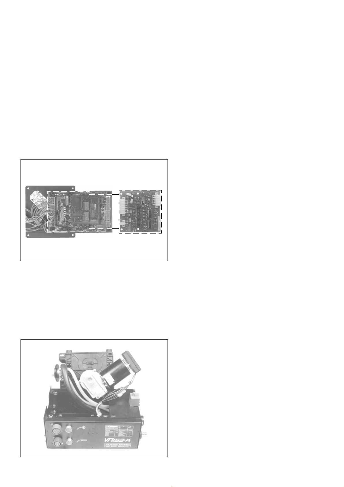
INDICATIONS DEL SUR LE FRONT
TRAVAUX DE SERVICE RECOMMANDÉS
DEL de réseau
L’indication DEL verte est allumée, quand les tensions d’alimentation de réseau sont actives et l’appareil est connecté.
DEL de tension trop élevée
L’indication DEL rouge est allumée, quand l’alimentation de
réseau diffère de la valeur standard de +/-10%.
DEL de température trop élevée
L’indication DEL rouge est allumée lors d’un défaut dans le
système de refroidissement ou quand le facteur de service de la
machine fut dépassé.
REMPLACEMENT DU TIROIR: fig. 13
- Déconnecter l’interrupteur principal
- Déconnecter la commande par robot
- Enlever de derrière la plaque d’options
- Déconnecter les connexions à fiches
TOUTES LES SEMAINES
- Liquide de refroidissement (s’il y en a)
- État de la torche de soudage
- Introduction de fil et système transporteur de fil
TOUS LES ANS
- Purge de l’appareil d’avance de fil par air comprimé sec
- Vérification des éléments mécaniques
- Gamme de réglage du nombre de tours du moteur
- Vérification générale
- Vérification du filtre à gaz (seulement pour l’option contrôleur
de gaz)
Fig. 13
ENLÈVEMENT DE LA PLAQUE DE MOTEUR: fig. 14
l Déconnecter l’interrupteur principal
l Ouvrir les 4 vis de fixation de la plaque de moteur
l Tourner la plaque de moteur légèrement vers la gauche et la
soulever d’abord au raccord central
l Déconnecter le transmetteur de la valeur effective
Fig. 14
18
Page 55

Ersatzteilliste
D
Schaltplan
Spare Parts List
GB
Circuit Diagram
Liste de pièces de rechange
F
Schéma de connexions
Lista parti di ricambio
I
Schema
Lista de repuestos
E
Esquema de cableado
Lista de peças sobresselentes
P
Esquema de conexões
Onderdelenlijst
NL
Bedradingsschema
Reservdelsliste
N
Koblingsplan
Seznam náhradních dílů
CZ
Schéma zapojení
Список запасных частей
RUS
Электрическая схема
Zoznam náhradných dielov
SK
Schéma zapojenia
ud_fr_st_tb_00149 012008
Page 56
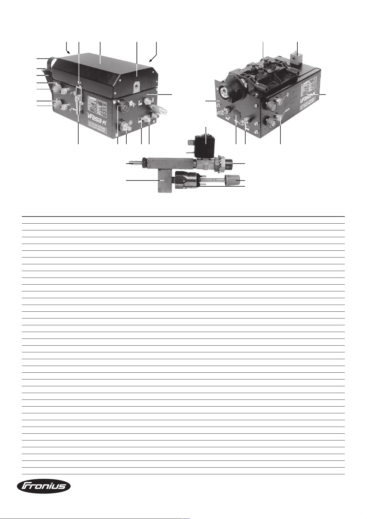
27,38
28
26
10
11
12
13
30 31
33 34 36
25
4
2,3
5-9
35
15
1
16 17
29
20
37
19
22
24
32
18
21
14
23
POS. BENENNUNG ARTICLE DENOMINATION
1 DRUCK GEHÄUSE VR153 TIME CASE VR153 TIME CHASSIS VR153 TIME 45.0200.0890
2 DRUCK FRONTPL.U. VR153 FRONT PANEL BELOW VR153 PANNEAU AVANT INFERIEUR 32.0409.1729
3 DRUCK FRONTPL.U. VR153-4R W RO FRONT PANEL BELOW VR153-4R W PANNEAU AVANT INFERIEUR 32.0409.1880
4 DRUCK RÜCKFR. VR153 TIME REAR PANEL VR153 TIME PANNEAU ARRIERE VR153 TIME 45.0200.0891
5 MOTORPL. 42V 4R EC. O.RÄ. M.T. MOTOR PLATE 42V 4R EC. W.WH. PLAQUE DE MOTEUR 42V 4R EC 44.0001.1093
6 MOTORPL. 42V 4R D-ZA O.RÄ.M.T MOTOR PLATE 42V 4R D-ZA PLAQUE DE MOTEUR 42V 4R D-ZA 44.0001.1095
7 MOTORPL. 42V 4R F-ZA O.RÄ.M.T. MOTOR PLATE 24V 4R F-ZA PLAQUE DE MOTEUR 24V 4R F-ZA 44.0001.1096
8 MOTORPL. 42V 4R F-ZA 1.2TI 30M MOTOR PLATE 42V 4R F-ZA 1.2TI PLAQUE DE MOTEUR 42V 4R F-ZA 44.0001.1058
9 MOTORPL.42V 4R EC.1.2TI 30M MT MOTOR PLATE 42V 4R EC.1.2TI PLAQUE DE MOTEUR 42V 4R EC 44.0001.1065
10 STECKDOSENGEHÄUSE EB 20 PLUG-HOUSING EB 20 LOGEMENT PRISE EB 20 43.0003.0256
11 STECKDOSENEINSATZ 20 14 PLUG-SOCKET-INSERT 20 14 SUPPORT PRISE INTERNE 43.0003.0248
12 STECKDOSENGEHÄUSE EB 18 PLUG-HOUSING EB 18 LOGEMENT PRISE EB 18 43.0003.0255
13 STECKDOSENEINSATZ 18 4 PLUG-SOCKET-INSERT 18 4 SUPPORT PRISE INTERNE 43.0003.0245
14 TASTER N290/K1 GRÜN TRIGGER GREEN N 290/K1 GACHETTE VERTE N 290 K1 43.0002.0079
15 MAGNETVENTIL-KL.42 0-10 G1/8" MAGNETIC VALVE SMAL 42 0-10 ELECTROVANNE 42 0/10 43.0013.0004
16 MUTTER-LOCKNUT R3/8" SW21x4.5 LOCKNUT R 3/8" SW 21X6.5 CONTRE ECROU 42.0001.0133
17 ANSCHLUSSCHR. R3/8" SW21X45 PICK-UP TUBE R3/8" SW21X45 TUBE PICK UP SW 21X45 42.0001.2666
18 MAGNETVENTILA. R1/8"R3/8" SOLENOID VALVE CONNECTION RACORD VALVE SOLENOID 42.0401.0085
19 SCHLAUCHTÜLLE M.O-RG. R1/8"x31 HOSE CONNECTION R1/8"/D=7.5 RACCORD R1/8 7,5 42.0001.0090
20 STROMSTECKER EB 50-70 600 CURRENT PLUG 5O-7OMM2/6OO A PRISE COURANT 50/70 600A 43.0003.0146
21 DREHKNOPF D=16 GR GR GR TURN KNOB D=16 GREY/GREY/GREY BOUTON A 3 POSITIONS 16 42.0406.0081
22 DRUCKWÄCHTERAUFN. VR153 MOUNTING PRESSURE CONTR.VR153 CONTROLE DE MONTEE DE 44.0001.0709
23 DRUCKWÄCHT EPDM M10X1 S 0,1-1B WATER FLOW SWITCH INTERRUPTEUR DEBIT EAU 43.0002.0005
24 SCHNELLKUPPL.WASSER 21KATS06 QUICK CONNECTION W RACCORD RAPIDE 44.0001.0348
25 DECKEL SW VR153 TIME COVER PLATE BLACK VR153 TIME COUVERCLE NOIR VR153 TIME BE2.0200.8525
26 SCHLP.HALT.SW PR4-O/M HOSE PACK MOUNT. BLACK PR4-0/M MONTAGE FAISCEAU NOIR PR4 BE2.0200.2677
27 ZUGENTLASTUNG SW VR152-MP TRACTION RELEASE BLACK ECROU FREIN VR153-MP BE2.0200.7817
28 RÄNDELSCHRAUBE M8x25 KNURLED SCREW ECROU MOLETE 42.0401.0004
29 KISTENVERSCHLUSS 95X30X15 BOX-FASTENER 95x30x15 FIXATIONS BOITE 95X30X15 42.0407.0055
30 VERSCHLUSSHAKEN FORM3 25MM VZ LOCK-CLAMP FORM3 25MM VZ FERMETURE CROCHET 42.0200.2474
31 SCHARNIER S053B120 S6 HINGE SO53B120 S6 CHARNIERE SO53B120 S6 42.0200.6480
32 ABDECKKAPPE 32.0/34.8/11.5/3.2 HEYCO-COVERING D=32MM COUVERCLE 32.0/34.8/11.5/3.2 42.0300.1770
33 FRONTPL.O.SW VR123-R FRONT PANEL ABOVE BLACK VR123- PANNEAU AVANT INFERIEUR BE2.0200.4755
34 RÜCKFRONT(DECKEL)SW VR153 TIME REAR PANEL VR153 TIME PANNEAU ARRIERE VR153 TIME BE2.0200.8527
35 FRONTPL.U. SW VR153 TIME FRONT PANEL VR153 TIME PANNEAU FRONTAL VR153 TIME BE2.0200.8849
36 DRAHTEINLAUFBLOCK VR149/153/- WIRE-INFEED-BLOCK VR149/153/- BOBINE FIL DEVIDOIR 44.0450.0893
37 BUCHSENGEHÄUSE 23 37 EINB. SOCKET-CASE 23 37 CASE SUPPORT 23 37 43.0003.0482
38 ZUGENTLASTUNG SW VR123-2R/4R TRACTION RELEASE BLACK ECROU FREIN VR123-3R/4R BE2.0200.7817
VR153-K / TIME 4.045.777 / 000 / 001 / 002 / 4.045.773.000 / 000
Ersatzteilliste / Spare parts list / Listes de pièces de rechange / Lista de repuestos / Lista de pecas sobresselentes / Lista dei Ricambi
el_fr_st_dv_00032 012000
1/1
Page 57

Motorplate 42V 4R
Ersatzteilliste / Spare parts list / Listes de pièces de rechange / Lista de repuestos / Lista de pecas sobresselentes / Lista dei Ricambi
el_fr_st_mp_01220 012008
1/4
Page 58

Motorplate 42V 4R
Ersatzteilliste / Spare parts list / Listes de pièces de rechange / Lista de repuestos / Lista de pecas sobresselentes / Lista dei Ricambi
el_fr_st_mp_01220 012008
2/4
Page 59

Motorplate 42V 4R
Ersatzteilliste / Spare parts list / Listes de pièces de rechange / Lista de repuestos / Lista de pecas sobresselentes / Lista dei Ricambi
el_fr_st_mp_01220 012008
3/4
Page 60
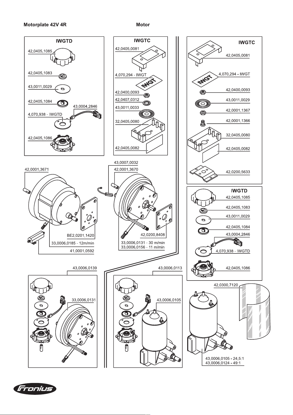
Motorplate 42V 4R
Ersatzteilliste / Spare parts list / Listes de pièces de rechange / Lista de repuestos / Lista de pecas sobresselentes / Lista dei Ricambi
el_fr_st_mp_01220 012008
4/4
Page 61
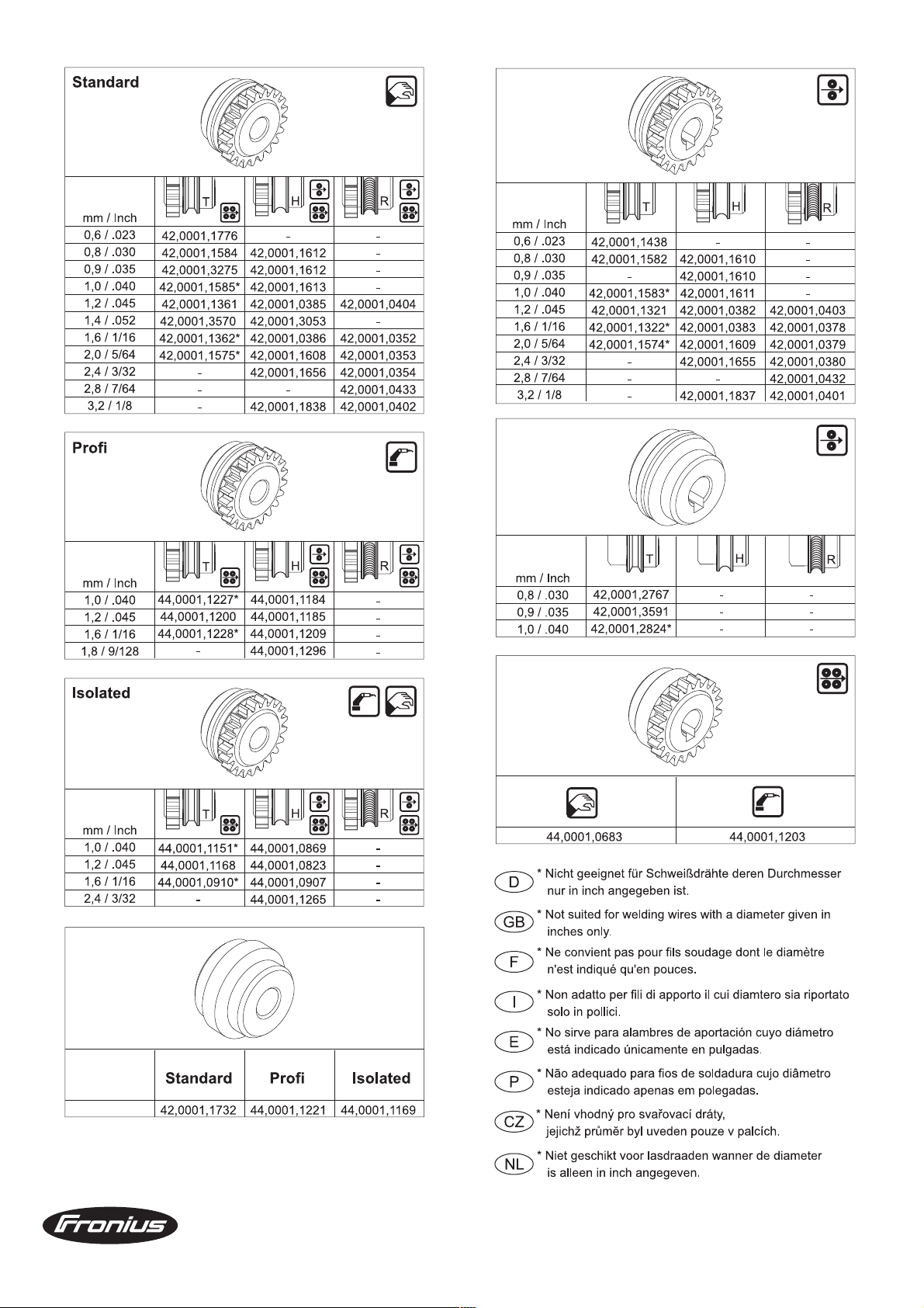
Wire feed rollers
Ersatzteilliste / Spare parts list / Listes de pièces de rechange / Lista de repuestos / Lista de pecas sobresselentes / Lista dei Ricambi
ud_fr_st_mp_00094 012008
1/1
Page 62

9
2
6
7
434
3
5
1
10
8
2
7
POS. BENENNUNG ARTICLE DENOMINATION
1 DRUCK FRONTPL. ROBOTER INTERF. FRONT PANEL ROBO.INTF. PANNEAU FRONTAL ROBO.INTF. 42.0409.2524
2 PRINT IRO 34 A PC-BOARD IRO 34 A CIRCUIT ELECTRONIQUE IRO 34 A 4.070.283
3 SICHKLEIN 0.125 T 19372 FUSE SMALL 0.125 T 19372 FUSIBLE PETIT 0.125 T 19372 41.0007.0043
4 SICHKLEIN 0.63 T 19372 FUSE SMALL 0,63 T 19372 FUSIBLE PETIT 0.63 T 19372 41.0007.0104
5 FILTERGLAS BR TS330/450 FILTER-GLASS BR TS330/450 FILTRE VERRE 42.0300.1643
6 KABELB. ROB.-INTERF. TS330 CABLE HARNESS ROB.INTERF.TS330 HARNAIS DE CABLE 43.0004.3283
7 BUCHSENGEHÄUSE 23 37 EINB. SOCKET-CASE 23 37 CASE SUPPORT 23 37 43.0003.0482
8 VERB.LEITUNG INTER. VR153 CONNECTION LINE INTER. VR153 CONNECTEUR DE CONTROLE 43.0004.1142
9 ABDECKPL. SUBMIN ROB.INTERF. COVER PLATE SUBMIN COUVERCLE DE TOLE GRADUE 42.0200.9196
10 PRINT DIGIR PC-BOARD DIGIR CIRCUIT ELECTRONIQUE DIGIR 4.070.513
ROBOTERINTERFACE TS-ST 153 4,100,011 / 4,100,146
Ersatzteilliste / Spare parts list / Listes de pièces de rechange / Lista de repuestos / Lista de pecas sobresselentes / Lista dei Ricambi
el_fr_st_so_00190 012000
1/1
Page 63
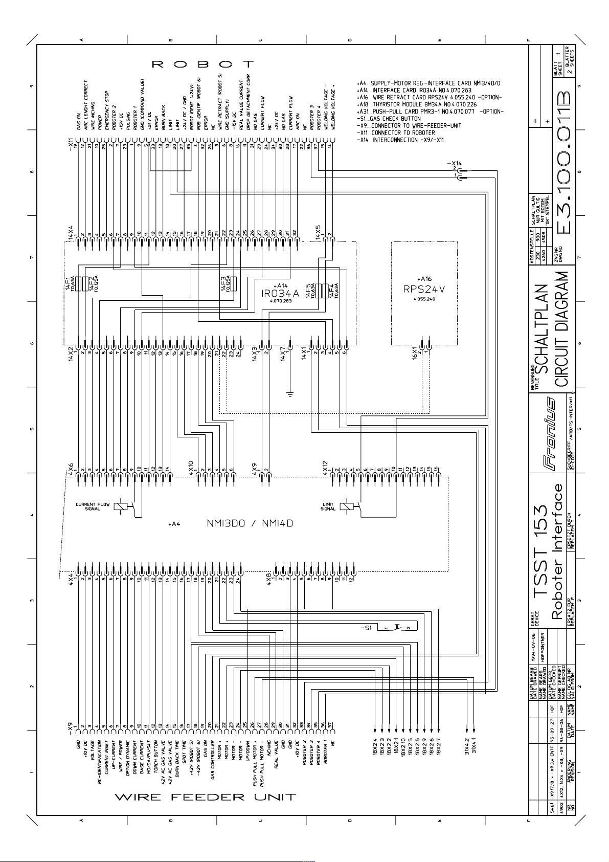
Page 64

Page 65

Page 66

Page 67

Page 68
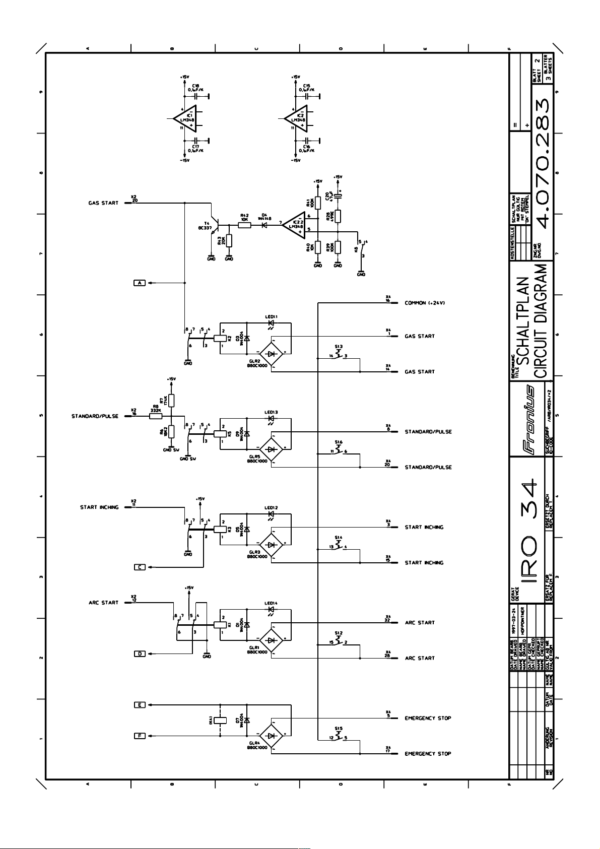
Page 69
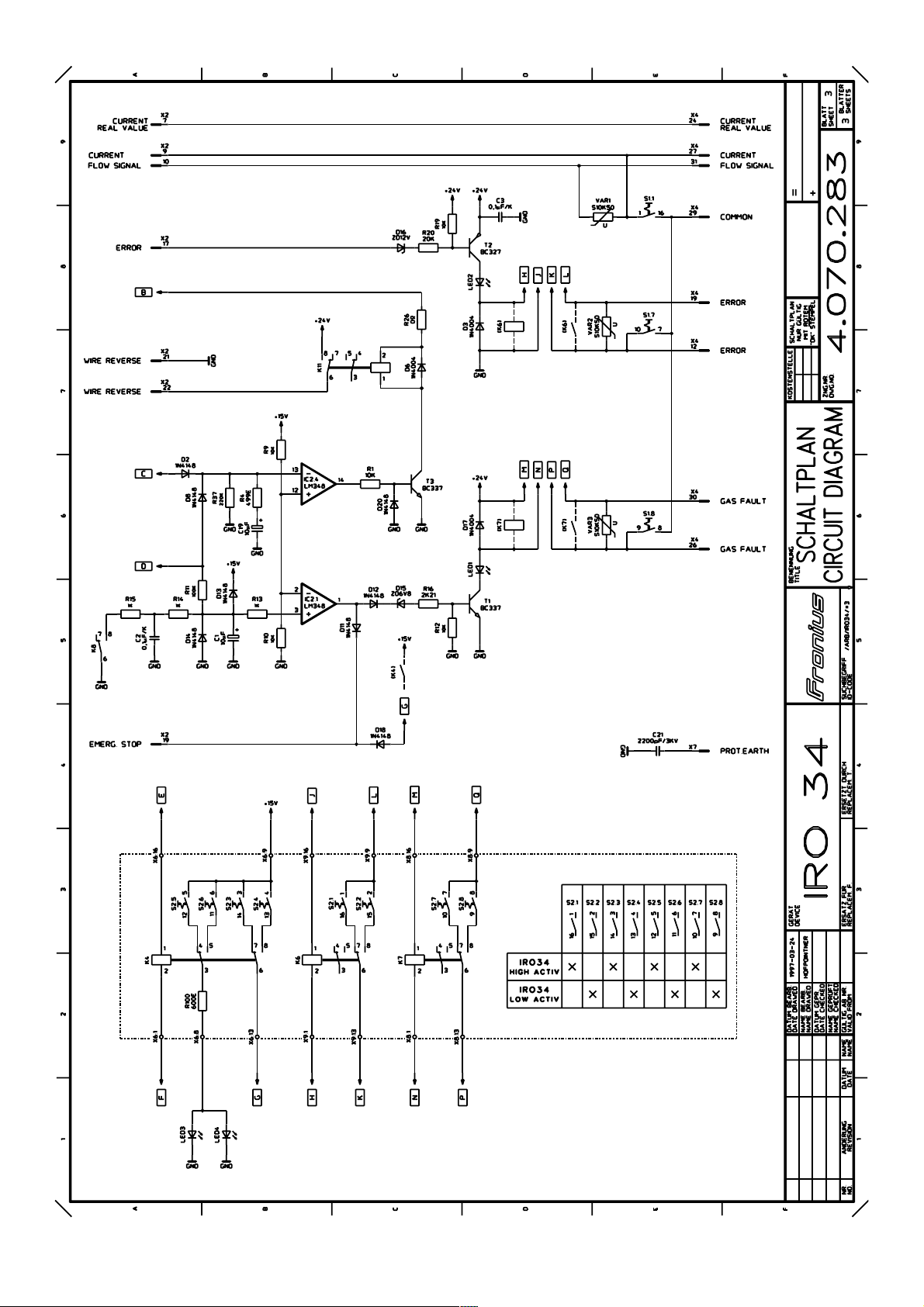
Page 70

FRONIUS INTERNATIONAL GMBH
Buxbaumstraße 2, A-4600 Wels, Austria
Tel: +43 (0)7242 241-0, Fax: +43 (0)7242 241-3940
E-Mail: sales@fronius.com
www.fronius.com
Under http://www.fronius.com/addresses you will find all addresses
www.fronius.com/addresses
of our Sales & service partners and Locations.
ud_fr_st_so_00082 012008
 Loading...