

Page 1

Operating
Instructions
Profibus
Twin Profibus
Bedienungsanleitung
DE
Operating Instructions
EN
Instructions de service
FR
Kullanım kılavuzu
TR
42,0410,0636 002-02032023
Page 2

Page 3

Inhaltsverzeichnis
Allgemeines 4
Sicherheit 4
Grundlagen 4
Gerätekonzept 4
Anschlüsse am Interface - TS/TPS, MW/TT Geräteserie 4
Zusatzhinweise 4
Anwendungsbeispiel - TS/TPS, MW/TT Geräteserie 5
Hinweise zum Einbau der externen Variante des Interfaces 5
Feldbus-Koppler anschließen und konfigurieren 6
Sicherheit 6
Bedienelemente und Anschlüsse Feldbus- Koppler 6
Feldbus-Koppler anschließen und konfigurieren 6
Konfiguration Slave-Adresse 8
Eigenschaften der Datenübertragung 9
RS 485 Übertragungstechnik 9
LWL Netze 9
Sicherheitseinrichtung 10
Fehlerdiagnose, Fehlerbehebung 11
Sicherheit 11
Allgemeines 11
Betriebszustand LEDs 11
Feldbus-Status LEDs 14
Profibus-Konfigurationsdaten-Fehler 14
Angezeigte Service-Codes 16
Signalbeschreibung Profibus / Twin Profibus 17
Allgemeines 17
Betriebsarten der Stromquelle - TS/TPS, MW/TT Geräteserie 17
Übersicht 17
Ein- und Ausgangssignale für MIG/MAG - TS/TPS, MW/TT Geräteserie 18
Eingangssignale (vom Roboter zur Stromquelle) 18
Ausgangssignale (von der Stromquelle zum Roboter) 19
Ein- und Ausgangssignale für WIG - TS/TPS, MW/TT Geräteserie 21
Eingangssignale (vom Roboter zur Stromquelle) 21
Einstellung Pulsbereich WIG 22
Ausgangssignale (von der Stromquelle zum Roboter) 22
Ein- und Ausgangssignale für CC/CV - TS/TPS, MW/TT Geräteserie 24
Eingangssignale (vom Roboter zur Stromquelle) 24
Ausgangssignale (von der Stromquelle zum Roboter) 25
Ein- und Ausgangssignale für Standard-Manuell - TS/TPS, MW/TT Geräteserie 27
Eingangssignale (vom Roboter zur Stromquelle) 27
Ausgangssignale (von der Stromquelle zum Roboter) 28
Signalbeschreibung Twin Profibus für MIG/MAG - TS/TPS Geräteserie 30
Eingangssignale (vom Roboter zur Stromquelle) 30
Ausgangssignale (von der Stromquelle zum Roboter) 31
Konfigurationsbeispiele Profibus 33
Allgemeines 33
Konfigurationsbeispiele 33
Gerätestammdatei (GSD) für BK3120 36
Allgemeines 36
Einzutragende Daten 36
Gerätestammdatei (GSD) für BC3100 37
Allgemeines 37
Einzutragende Daten 37
Technische Daten 38
Technische Daten Profibus-Koppler BK3120 38
DE
3
Page 4

Allgemeines
(2)
(1)
Sicherheit
Gefahr durch Fehlbedienung und fehlerhaft durchgeführte Arbeiten.
Schwerwiegende Personen- und Sachschäden können die Folge sein.
▶
▶
▶
▶
▶
Grundlagen Profibus ist ein Hersteller-unabhängiges, offener Feldbus-Standard für vielfältige
Anwendungen in der Fertigungs-, Prozess- und Gebäudeautomation. Profibus ist
sowohl für schnelle, zeitkritische Datenübertragungen, als auch für umfangreiche und komplexe Kommunikationsaufgaben geeignet.
WARNUNG!
Alle in dieser Bedienungsanleitung angeführten Arbeiten dürfen nur von geschultem Fachpersonal durchgeführt werden.
Alle in dieser Bedienungsanleitung beschriebenen Funktionen dürfen nur
von geschultem Fachpersonal angewandt werden.
Alle beschriebenen Arbeiten erst ausführen und alle beschriebenen Funktionen erst anwenden wenn folgende Dokumente vollständig gelesen und verstanden wurden:
Diese Bedienungsanleitung
Sämtliche Bedienungsanleitungen der Systemkomponenten, insbesondere
Sicherheitsvorschriften
Gerätekonzept Profibus zeichnet sich durch geringes Bauvolumen und hohe Modularität aus.
Die einfache und platzsparende Montage auf einer Norm C-Schiene und die direkte Verdrahtung von Aktoren und Sensoren ohne Querverbindungen zwischen
den Klemmen standardisiert die Installation. Das einheitliche Beschriftungskonzept erleichtert zusätzlich die Installation.
Anschlüsse am
Interface - TS/
TPS, MW/TT
Geräteserie
(1) Zugentlastung mit Kabel-
durchführungen
zum Durchführen der Datenleitung Profibus und der Spannungsversorgung für den Feldbus-Koppler
(2) Anschluss LocalNet
zum Anschließen des Verbindungs- Schlauchpaketes.
Zusatzhinweise HINWEIS! Solange das Roboterinterface am LocalNet angeschlossen ist, bleibt
automatisch die Betriebsart „2-Takt Betrieb“ angewählt (Anzeige: Betriebsart 2Takt Betrieb).
4
Page 5

Anwendungsbei-
(1) (2)
(3)
(4)
(5)
(6) (7)
(8)
(9)
(10)
spiel - TS/TPS,
MW/TT Geräteserie
Nähere Informationen zur Betriebsart „Sonder-2-Takt Betrieb für Roboterinterface“ den Kapiteln „MIG/MAG-Schweißen“ und „Parameter Betriebsart“ der Bedienungsanleitung der Stromquelle entnehmen.
DE
Hinweise zum
Einbau der externen Variante
des Interfaces
(1) Stromquelle
(2) Kühlgerät
(3) Profibus
(4) Verbindungs-Schlauchpaket
(5) Schweißbrenner
HINWEIS! Beim Einbau der externen Variante des Interfaces folgende Richtlinien beachten:
Die Verlegung der Kabel hat getrennt von netzbehafteten Leitungen zu erfol-
-
gen
Der Einbau des Feldbus-Kopplers hat getrennt von netzbehafteten Leitun-
-
gen oder Komponenten zu erfolgen
Der Feldbus-Koppler darf nur an einem vor Verschmutzung und Wasser
-
geschützten Ort eingebaut werden
Es ist dafür zu sorgen, dass die 24V Versorgungsspannung sicher getrennt ist
-
von Stromkreisen mit höherer Spannung.
(6) Robotersteuerung
(7) Schweißdraht-Fass
(8) Roboter
(9) Schweißbrenner
(10) Drahtvorschub
5
Page 6

Feldbus-Koppler anschließen und konfigurieren
BK3120
BECKHOFF
(1)
(2)
(3)
Sicherheit
Bedienelemente
und Anschlüsse
Feldbus- Koppler
WARNUNG!
Gefahr durch elektrischen Strom.
Schwere Personen- und Sachschäden können die Folge sein.
Vor Beginn der Arbeiten alle beteiligten Geräte und Komponenten ausschal-
▶
ten und von Stromnetz trennen.
Alle beteiligten Geräte und Komponenten gegen Wiedereinschalten sichern.
▶
Nach dem Öffnen des Gerätes mit Hilfe eines geeigneten Messgerätes si-
▶
cherstellen, dass elektrisch geladene Bauteile (beispielsweise Kondensatoren) entladen sind.
(1) Anschluss-Stecker Profibus
(2) Adresswähler
(3) Anschlüsse für externe Span-
nungsversorgung
WICHTIG! Externe Spannungsversorgung darf nicht von der Stromquelle
erfolgen. Für die externe Spannungsversorgung Roboter oder Steuerung
verwenden.
Feldbus-Koppler
anschließen und
konfigurieren
VORSICHT!
Gefahr durch elektrischen Strom.
Schwere Sachschäden können die Folge sein.
Vor Beginn der Arbeiten sicherstellen, dass die Kabel für die externe Span-
▶
nungsversorgung des Interfaces spannungsfrei sind und bis zum Abschluss
aller Arbeiten spannungsfrei bleiben.
6
Page 7

Feldbus-Koppler im Interface auf isolierter Hutschiene montiert - TS/TPS, MW/TT Geräteserie
3: RxD/TxD-P
5: DGND
8: RxD/TxD-N
6
1
WICHTIG! Bei Montage des Feldbus-Kopplers nur „isolierte“ Hutschiene verwenden. Darauf achten, dass Hutschiene keinen elektrischen Kontakt zu der Erde
des Schweißgerätes hat.
Interface-Deckel demontieren
1
Zugentlastung vom Interface abmontieren
2
Datenleitung Profibus und Kabel für die externe Spannungsversorgung durch
3
Kabeldurchführung in der Zugentlastung durchführen
DE
Datenleitung Profibus am An-
4
schluss- Stecker Profibus anschließen
Externe Spannungsversorgung von
5
Roboter oder Steuerung an die
Anschlüsse für die externe Spannungsversorgung am FeldbusKoppler anschließen
Datenleitung Profibus und Kabel
6
für die externe Spannungsversorgung mittels Kabelbindern an der
Kabeldurchführung in der Zugentlastung montieren
Zugentlastung mit dem original
7
Befestigungsmaterial am Interface
Anschlussbelegung Profibus
so montieren, dass die Zugentlastung ihre Originalposition wieder
einnimmt
HINWEIS! Mögliche Störung der Datenkommunikation durch fehlende Schirmverbindung. Darauf achten, dass Schirm des Kabels an beiden Enden im Stecker
angeschlossen ist.
WICHTIG! Vor Inbetriebnahme kontrollieren ob Schirm Roboter seitig mit Erde
Roboter verbunden ist.
Bei Systemen mit mehr als zwei Stromquellen die Stromquellen parallel verdrahten.
HINWEIS! Feldbus-Kabel an den Enden mit Widerständen versehen, um Refle-
xionen und damit Übertragungsprobleme zu vermeiden.
7
Page 8

Stromquelle 1
RxD/TxD-P (3)
DGND (5)
Stromquelle 2
RxD/TxD-N (8)
RxD/TxD-P (3)
DGND (5)
RxD/TxD-N (8)
Hutschiene
Hutschiene
Abschirmung
Anschlussbelegung Profibus
0
1
2
3
4
5
6
7
8
9
0
1
2
3
4
5
6
7
8
9
x 1
x 10
Bei TS/TPS, MW/TT Geräteserie:
LocalNet-Stecker vom Verbindungs-Schlauchpaket an Anschluss LocalNet
8
am Interface anschließen
Konfiguration
Slave-Adresse
Slave-Adresse über die zwei Dreh-Wahlschalter einstellen.
Default-Einstellung = 11
Es sind alle Adressen erlaubt, jede Adresse darf im Netzwerk nur einmal vorkommen.
Sicherstellen, dass alle beteiligten Geräte und Komponenten vom Netz ge-
1
trennt und ausgeschaltet sind
Sicherstellen, dass das Interface vom Netz getrennt ist
2
Mittels Schraubendreher Schalter auf gewünschte Position bringen.
3
Oberer Schalter ist Einer-Multiplikator
-
Unterer Schalter ist Zehner-Multiplikator
-
Wichtig! Darauf achten, dass Schalter richtig einrasten
Beispiel
Adresse 34 einstellen:
Oberer Drehwahlschalter : 4
-
Unterer Drehwahlschalter : 3
-
Interface-Deckel mit den Originalschrauben so montieren, dass der Inter-
4
face-Deckel seine Originalposition einnimmt
8
Page 9

Eigenschaften der Datenübertragung
DE
RS 485 Übertragungstechnik
Netzwerk Topologie
Linearer Bus, aktiver Busabschluss an beiden Enden, Stichleitungen sind
möglich
Medium
Abgeschirmtes verdrilltes Kabel, Schirmung muss ausgeführt werden
Anzahl von Stationen
32 Stationen in jedem Segment ohne Repeater. Mit Repeatern erweiterbar bis
127
Max. Bus Länge ohne Repeater
100m bei 12 MBit/sKabel A: 200 m bei 1500 KBit/s, bis zu 1,2 km bei 93,75
KBit/s
Max. Bus Länge mit Repeater
Durch Leitungsverstärker (Repeater) kann die max. Buslänge bis in den 10 kmBereich vergrößert werden. Die Anzahl der möglichen Repeater ist mindestens
3 und kann je nach Hersteller bis zu 10 betragen
Übertragungsgeschwindigkeit
9,6; 19,2: 93,75; 187,5; 500; 1500 KBit/s, bis 12 MBit/s wird automatisch eingestellt
Steckverbinder
9-Pin D-Sub Steckverbinder
Prozessdaten-Breite
Profibus (4,100,231,4,100,233) 112 Bit (Standardkonfiguration)
Twin Profibus (4,100,403) 176 Bit (Standardkonfiguration)
LWL Netze
Prozessdaten-Format
Motorola
Netzwerk Topologie
Subring
Medium
APF (Kunststoff) - Faser (Z1101)
min./max. Länge zwischen zwei Stationen
Koordinator - Station: L≥ 1 m L ≤ 34 m
Station - Station: L ≥ 1 m L ≤ 25 m
Station - Koordinator: L ≥ 0 m L ≤ 46 m
Anzahl von Stationen
93,75 kBaud: 13 187,5 kBaud:12500 kBaud:
12
Übertragungsgeschwindigkeit
93,75 187,5 500 1500 KBit/s
1500 kBaud:
10
Schalterstellung
S1 = 0, S2 = 0 S1 = 0, S2 = 0 S1 = 0, S2 = 0 S1 = 0, S2 = 0
9
Page 10

Bus-Anschluss
2 x HP Simplex
Prozessdaten-Breite
Profibus LWL (4,100,232) 112 Bit
Sicherheitseinrichtung
Damit die Stromquelle den Vorgang bei ausgefallener Datenübertragung unterbrechen kann, verfügt der Feldbus-Knoten über eine Abschaltüberwachung. Findet innerhalb von 700ms keine Datenübertragung statt, werden alle Ein- und
Ausgänge zurückgesetzt und die Stromquelle befindet sich im Zustand „Stop“.
Nach wiederhergestellter Datenübertragung erfolgt die Wiederaufnahme des
Vorganges durch folgende Signale:
Signal „Roboter ready“
-
Signal „Quellen-Störung quittieren“
-
10
Page 11

Fehlerdiagnose, Fehlerbehebung
BK3120
BECKHOFF
(1)
(2)
(3)
DE
Sicherheit
Allgemeines
WARNUNG!
Gefahr durch elektrischen Strom.
Schwere Personen- und Sachschäden können die Folge sein.
Vor Beginn der Arbeiten alle beteiligten Geräte und Komponenten ausschal-
▶
ten und von Stromnetz trennen.
Alle beteiligten Geräte und Komponenten gegen Wiedereinschalten sichern.
▶
Nach dem Öffnen des Gerätes mit Hilfe eines geeigneten Messgerätes si-
▶
cherstellen, dass elektrisch geladene Bauteile (beispielsweise Kondensatoren) entladen sind.
(1) LEDs Betriebszustand
(2) LEDs Feldbusstatus
(3) LEDs Versorgungsanzeige
linke LED ... zeigt die Ver-
-
sorgung des Feldbus-Kopplers an
rechte LED... zeigt die Ver-
-
sorgung der Powerkontakte
an
Betriebszustand
LEDs
Blinkcode
Tritt ein Fehler auf, signalisieren die Feldbus-Status LEDs bzw. die Betriebszustand-LEDs die Art des Fehlers und die Fehlerstelle.
WICHTIG! Nach der Fehlerbeseitigung beendet der Feldbus-Koppler in manchen Fällen die Blinksequenz nicht. Durch Aus- und Einschalten der Versorgungsspannung oder durch einen Software Reset den Feldbus-Koppler neu starten.
Die Betriebszustand LEDs zeigen die lokale Kommunikation zwischen FeldbusKoppler und Feldbus-Klemmen. Die grüne LED leuchtet bei fehlerfreiem Betrieb.
Die rote LED blinkt mit zwei unterschiedlichen Frequenzen, wenn ein KlemmbusFehler auftritt.
11
Page 12

(a) (b) (c)
Fehlercode
Schnelles Blinken:
a)
Start des Fehlercodes
Erste langsame Impulse:
b)
Fehlerart
Zweite langsame Impulse:
c)
Fehlerstelle
WICHTIG! Die Anzahl der Impulse
zeigt die Position der letzten FeldbusKlemme vor dem Auftreten des Fehlers an. Passive Feldbus-Klemmen (z.B.
Einspeiseklemmen) werden nicht mitgezählt.
Fehler-Argument Ursache Behebung
ständiges,
konstantes
Blinken
1 Impuls 0 Impulse EEPROM-Prüfsum-
0 Impulse Probleme mit elek-
tromagnetischer
Verträglichkeit (EMV)
menfehler
1 Impuls Überlauf Inline-
Code-Buffer.
Zu viele Einträge in
der Tabelle
2 Impulse Unbekannter Daten-
typ
Spannungsversorgung
auf Unter- oder Überspannungs-Spitzen kontrollieren
EMV-Maßnahmen ergreifen
Liegt ein K-Bus Fehler
vor, kann durch erneutes
Starten (Aus- und wieder Einschalten) des
Feldbus-Kopplers der
Fehler lokalisiert werden
Hersteller-Einstellung
mit der KS2000 setzen
Weniger Klemmen stecken
Software-Update des
Feldbus-Kopplers
durchführen
2 Impulse 0 Impulse programmierte Konfi-
3 Impulse 0 Impulse Klemmenbus Kom-
12
n Impulse
(n>0)
guration falscher Tabelleneintrag / Buskoppler
Tabellenvergleich
(Klemme n) falsch
mandofehler
Programmierte Konfiguration auf Richtigkeit
überprüfen
Falscher Tabelleneintrag / Buskoppler
Keine Klemme gesteckt,
Klemme anhängen
Page 13

Fehler-Ar-
Fehlercode
Eine Klemme ist defekt
gument Ursache Behebung
Angeschlossene Klemmen halbieren und
prüfen, ob der Fehler bei
den übrigen Klemmen
noch auftritt. Dies weiterführen, bis die defekte Klemme gefunden ist
DE
4 Impulse 0 Impulse Klemmenbus Daten-
fehler
5 Impulse n Impulse Klemmenbus Fehler
9 Impulse 0 Impulse Chek-Summenfehler
13 Impulse 0 Impulse Laufzeit K-Bus
n Impulse Bruchstelle hinter
Klemmen (0:Koppler)
bei Registerkommunikation mit Klemmen
im Programmflash.
n Impulse Die Busklemme n
stimmt nicht mit der
Konfiguration, die
beim Erstellen des
Bootprojekts existierte überein
Kommandofehler
Prüfen, ob die n+1
Klemme richtig gesteckt
ist, gegebenenfalls tauschen
Kontrollieren, ob die
Endklemme KL9010 gesteckt ist
Klemmen austauschen
Herstellereinstellung
mit der KS 2000 setzen
Herstellereinstellung
mit der KS 2000 setzen,
damit wird das Bootprojekt gelöscht
Eine Busklemme defekt.
Busklemmen halbieren
und restliche Busklemmen auf Fehler prüfen.
Vorgang wiederholen,
bis defekte Busklemme
lokalisiert.
14 Impulse n Impulse n Busklemme hat fal-
sches Format
15 Impulse n Impulse Anzahl der Busklem-
men stimmt nicht
mehr
16 Impulse n Impulse Länge der K-Bus Da-
ten (Bitlänge) stimmt
nicht mehr. n =
bitlänge nach Booten
17 Impulse n Impulse Anzahl der Busklem-
men stimmt nicht
mehr. n = Anzahl der
Klemmen nach Booten
Koppler erneut starten,
falls der Fehler erneut
auftritt Busklemme tauschen
Koppler erneut starten.
Falls der Fehler erneut
auftritt, Herstellereinstellung mit der KS
2000 setzen
Koppler erneut starten.
Falls der Fehler erneut
auftritt, Herstellereinstellung mit der KS
2000 setzen
Koppler erneut starten.
Falls der Fehler erneut
auftritt, Herstellereinstellung mit der KS
2000 setzen
13
Page 14

Fehlercode
Fehler-Argument Ursache
Behebung
Feldbus-Status
LEDs
18 Impulse
Die Feldbus-Status LEDs zeigen die Betriebszustände des Feldbusses an. Die
Funktionen des Profibusses werden durch die LEDs „I/O RUN“, „BF“ und „DIA“
wiedergegeben.
I/O
RUN BF DIA Ursache Behebung
an aus aus Betriebszustand „RUN“
an an aus,
n Impulse Busklemmenbezeich-
nung stimmt nach
Reset nicht mehr. n =
Busklemmen-Nummer
Eingänge werden gelesen und Ausgänge gesetzt
Feldbus-Aktivität. Slave
blinkt
noch nicht parametriert
Koppler erneut starten.
Falls der Fehler erneut
auftritt, Herstellereinstellung mit der KS
2000 setzen
Ordnungsgemäße Funktion.
Keine Behebung erforderlich
Master starten
Parameter überprüfen
(Diagnosedaten, DIALED)
Konfiguration
überprüfen (Diagnosedaten, DIA-LED)
aus aus aus Klemmbuszyklus syn-
aus an an keine Busaktivität Master starten
aus an aus,
blinkt
Feldbus-Fehler mit Reaktion der Outputs:
werden 0
-
bleiben erhalten
-
chron DP-Watchdog
ausgeschaltet, kein Datenaustausch
Busfehler, Reaktion:
Klemmenbuszyklus wird
gestoppt
Master starten
Parameter überprüfen
(Diagnosedaten, DIALED)
Konfiguration
überprüfen (Diagnosedaten, DIA-LED)
SPS ist im „Stop“. SPS
starten
Buskabel prüfen
Master starten
Parameter überprüfen
(Diagnosedaten, DIALED)
Konfiguration
überprüfen (Diagnosedaten, DIA-LED)
Profibus-KonfigurationsdatenFehler
14
Fehler beim DP-Hochlauf
Anzeige eines Fehlers bei der Parametierung (UserPrmData) oder Konfiguration
(Cfg-Data). Anzeige durch Feldbus-LEDs und Diagnosedaten (DiagData). Identifizierung über Fehlercode und Fehlerargument.
Page 15

Fehler bei der Überprüfung der UserPrmData
Fehler-Code 1
reserviertes Bit in den UserPrmData ist auf falschen Wert gesetzt
-
oder die dem Bit in den UserPrmData entsprechende Funktion wird nicht
-
unterstützt
Das Fehlerargument beschreibt, in welchem UserPrmData-Byte der Fehler erkannt wurde (Offset des fehlerhaften Bytes + 1).
Fehler-Code 3
eine gewählte Kombination von Funktionen ist nicht erlaubt. Beschreibung
durch Fehlerargument.
Fehlerargument Beschreibung
1 Im synchron-Mode ist die Einstellung der Reaktion auf DP-
Fehler auf „Outputs unverändert“ nicht erlaubt
2 Die DPV1-MSAC-C1 Verbindung wurde vom Master akti-
viert, aber keine DPV1-MSAC_C1 Verbindung definiert
6 der Multi-Configurator Mode ist nicht erlaubt, wenn die
Überprüfung der CfgData abgeschaltet ist
8 Der Synchron-Mode darf nur aktiviert werden, wenn min-
destens ein DP-Output-Byte konfiguriert ist
10 Der optimierte Input-Zyklus ist nur im Synchron-Mode
möglich
DE
11 Die Länge der DP-Buffer überschreitet die Größe des DP-
RAMs im Profibus-Asic
12 Der Fast-FreeRun-Mode darf nicht zusammen mit dem
Synchron-Mode aktiviert werden
Fehler bei der Überprüfung der CfgData
Fehler-Code 2
ein Byte in den CfgData stimmt nicht. Fehler-Argument beschreibt, in welchem
CfgData-Byte der Fehler erkannt wurde (Offset des fehlerhaften Bytes+1)
Fehler-Code 5
die Länge der digitalen Outputs (in Bytes), die aus den CfgData berechnet wurden, stimmt nicht. Das Fehler-Argument enthält die erwartete Byte-Länge.
Fehler-Code 6
die Länge der digitalen Inputs (in Bytes), die aus den CfgData berechnet wurden, stimmt nicht. Das Fehler-Argument enthält die erwartete Byte-Länge.
Fehler-Code 7
zeigt verschiedene Fehler beim Überprüfen der CfgData. Das Fehler-Argument
beschreibt den Fehler.
Fehlerargument Beschreibung
1 Länge der empfangenen CfgData stimmt nicht
2 Syntax der empfangenen CfgData stimmt nicht
3 Länge der DP-Inputdaten, die aus den CfgData berechnet
wurde ist, zu groß
4 Länge der DP-Outputdaten, die aus den CfgData berech-
net wurde, ist zu groß
15
Page 16

Fehler beim Hochlauf des Slaves
Fehler-Code 8
die Länge der DP-Buffer überschreitet die Größe des DP-RAMs im ProfibusAsic. Das Fehler-Argument enthält die Differenz (geteilt durch 8). Deaktivierung der DP-Kommunikation.
Fehler-Code 9
zeigt verschiedene Fehler an, die beim Hochlauf des Gerätes auftreten. Das
Fehlerargument beschreibt den Fehler.
Fehlerargument Beschreibung
1 Länge der DP-Inputdaten ist zu groß (zu viele Module ge-
steckt)
2 Länge der DP-Outputdaten ist zu groß (zu viele Module
gesteckt)
3 Länge der CfgData ist zu groß (zu viele Module gesteckt)
Reaktion auf Profibus Fehler
Ein Profibus-Fehler (Ausfall des Masters, Abziehen des Profibus-Steckers, etc.)
wird durch Ablaufen des DP-Watchdogs (in der Regel im Bereich von 100 ms,
falls dieser Master nicht deaktiviert wurde) oder durch einen Bus-Timeout (Baudraten-Überwachungszeit ist mit 10 s eingestellt) erkannt.
Angezeigte Service-Codes
Reaktion auf die Outputdaten des Kopplers in den UserPrmData einstellen:
Byte Bit Wert Beschreibung
10 0-1 00
bin
Reaktion auf Profibus-Fehler: K-Bus-Zyklus
wird verlassen (Default, digitale Outputs werden 0, komplexe Outputs gehen auf einen projektierten Ersatzwert)
10 0-1 01
bin
Reaktion auf Profibus-Fehler: K-Bus-Outputs
werden 0
10 0-1 10
bin
Reaktion auf Profibus-Fehler: K-Bus-Outputs
bleiben unverändert
Eine detaillierte Beschreibung der angezeigten Service-Codes finden Sie im Kapitel „Fehlerdiagnose und Behebung“ der Bedienungsanleitung Ihrer Stromquelle.
16
Page 17

Signalbeschreibung Profibus / Twin Profibus
BK 3120
KL6021-0010
KL9010
Allgemeines Die folgenden Signalbeschreibungen gelten für ein Interface mit einer Kommuni-
kationsklemme KL 6021-0010 (Standardausführung)
Zusätzlich besteht die Möglichkeit, weitere Klemmen in ein Roboterinterface einzubauen. Die Anzahl ist jedoch durch die Gehäusegröße limitiert.
WICHTIG! Beim Einbau weiterer Klemmen ändert sich das Prozessdatenbild.
DE
Betriebsarten
der Stromquelle
- TS/TPS,
MW/TT Geräteserie
Übersicht Signalbeschreibung ‘Profibus/Twin Profibus’ setzt sich aus folgenden Abschnit-
Je nach eingestellter Betriebsart kann das Interface Profibus/Twin Profibus verschiedenste Ein- und Ausgangssignale übertragen.
Betriebsart E13 E12 E11
MIG/MAG Standard Schweißen 0 0 0
MIG/MAG Impuls LichtbogenSchweißen 0 0 1
Jobbetrieb 0 1 0
Parameteranwahl intern 0 1 1
WIG 1 1 0
CC/CV 1 0 1
Standard-Manuell Schweißen 1 0 0
CMT / Sonderprozess 1 1 1
ten zusammen:
Ein- und Ausgangssignale für MIG/MAG - TS/TPS, MW/TT Geräteserie
-
Ein- und Ausgangssignale für WIG - TS/TPS, MW/TT Geräteserie
-
Ein- und Ausgangssignale für CC/CV - TS/TPS, MW/TT Geräteserie
-
Ein- und Ausgangssignale für Standard-Manuell - TS/TPS, MW/TT Gerätese-
-
rie
Ein- und Ausgangssignale für Twin Profibus MIG/MAG - TS/TPS, MW/TT
-
Geräteserie
17
Page 18

Ein- und Ausgangssignale für MIG/MAG - TS/
TPS, MW/TT Geräteserie
Eingangssignale
(vom Roboter
zur Stromquelle)
Lfd. Nr. Signalbezeichnung Bereich Aktivität
E01 Gas Test - High
E02 Drahtvorlauf - High
E03 Drahtrücklauf - High
E04 Quellenstörung quittieren - High
E05 Positionssuchen - High
E06 Brenner ausblasen - High
E07 Nicht verwendet - -
E08 Nicht verwendet - -
E09 Schweißen Ein - High
E10 Roboter bereit - High
E11 Betriebsarten Bit 0 - High
E12 Betriebsarten Bit 1 - High
E13 Betriebsarten Bit 2 - High
E14 Masterkennung Twin - High
E15 Nicht verwendet - -
E16 Nicht verwendet - -
E17 - E23 Programmnummer 0 - 127 -
E24 Schweißsimulation - High
E25 - E32 Job-Nummer 0 - 99 -
Mit RCU 5000i und in Betriebsart Jobbetrieb
E17 - E23 Job-Nummer 256 - 999 -
E24 Schweißsimulation - High
E25 - E32 Job-Nummer 0 - 255 -
Leistung (Sollwert) 0 - 65535
(0 % - 100 %)
E33 - E40 High Byte - -
E41 - E48 Low Byte - -
Lichtbogen-Längenkorrektur
(Sollwert)
E49 - E56 High Byte - -
E57 - E64 Low Byte - -
E65 - E72 Nicht verwendet - -
0 - 65535
(-30 % - +30 %)
-
-
18
E73 - E80 Rückbrand (Sollwert) 0 - 255
(-200 ms - +200
ms)
-
Page 19

Lfd. Nr. Signalbezeichnung Bereich Aktivität
Ausgangssignale
(von der Stromquelle zum Roboter)
E81 - E88 Nicht verwendet - -
E89 - E96 Puls-/Dynamikkorrektur
(Sollwert)
E97 Synchro Puls disable - High
E98 SFI disable - High
E99 Puls-/Dynamikkorrektur dis-
able
E100 Rückbrand disable - High
E101 Leistungs-Vollbereich (0 - 30m)- High
E102 Nicht verwendet - -
E103 - E112 Schweißgeschwindigkeit 0 - 1023
Lfd. Nr. Signalbezeichnung Bereich Aktivität
A01 - A08 Fehlernummer 0 - 255 -
A09 Lichtbogen stabil - High
0 - 255
(-5 % - +5 %)
- High
(0 - 1023 cm/min)
-
-
DE
A10 Limit-Signal (nur in Verbin-
dung mit RCU 5000i)
A11 Prozess aktiv - High
A12 Hauptstrom-Signal - High
A13 Brenner-Kollisionsschutz - High
A14 Stromquelle bereit - High
A15 Kommunikation bereit - High
A16 Reserve - -
A17 Festbrand-Kontrolle - High
A18 Nicht verwendet - -
A19 Roboter-Zugriff (in Verbin-
dung mit RCU 5000i)
A20 Draht vorhanden - High
A21 Kurzschluss Zeitüberschrei-
tung
A22 Daten Dokumentation bereit - High
A23 Nicht verwendet - -
- High
- High
- High
A24 Leistung außerhalb Bereich - High
A25 - A32 Nicht verwendet - -
Schweißspannung (Istwert) 0 - 65535
(0 - 100 V)
A33 - A40 High Byte - -
A41 - A48 Low Byte - -
-
19
Page 20

Lfd. Nr. Signalbezeichnung Bereich Aktivität
Schweißstrom (Istwert) 0 - 65535
(0 - 1000 A)
A49 - A56 High Byte - -
A57 - A64 Low Byte - -
A65 - A72 Nicht verwendet - -
A73 - A80 Nicht verwendet - -
A81 - A88 Nicht verwendet - -
A89 - A96 Motorstrom (Istwert) 0 - 255
(0 - 5 A)
Drahtgeschwindigkeit (Ist-
wert)
A97 - A104 High Byte - -
A105 - A112 Low Byte - -
0 - 65535
(-327,68 - +327,67
m/min)
-
-
20
Page 21

Ein- und Ausgangssignale für WIG - TS/TPS,
MW/TT Geräteserie
Eingangssignale
(vom Roboter
zur Stromquelle)
Lfd. Nr. Signalbezeichnung Bereich Aktivität
E01 Gas Test - High
E02 Drahtvorlauf - High
E03 Drahtrücklauf - High
E04 Quellenstörung quittieren - High
E05 Positionssuchen - High
E06 KD disable - High
E07 Nicht verwendet - -
E08 Nicht verwendet - -
E09 Schweißen Ein - High
E10 Roboter bereit - High
E11 Betriebsarten Bit 0 - High
E12 Betriebsarten Bit 1 - High
DE
E13 Betriebsarten Bit 2 - High
E14 Nicht verwendet - -
E15 Nicht verwendet - -
E16 Nicht verwendet - -
E17 DC / AC - High
E18 DC- / DC+ - High
E19 Kalottenbildung - High
E20 Pulsen disable - High
E21 Pulsbereichs-Auswahl Bit 0 - High
E22 Pulsbereichs-Auswahl Bit 1 - High
E23 Pulsbereichs-Auswahl Bit 2 - High
E24 Schweißsimulation - High
E25 - E32 Jobnummer 0 - 99 -
Hauptstrom (Sollwert) 0 - 65535
(0 bis I
E33 - E40 High Byte - -
E41 - E48 Low Byte - -
max
)
-
Externer Parameter (Soll-
wert)
E49 - E56 High Byte - -
E57 - E64 Low Byte - -
E65 - E72 Nicht verwendet - -
0 - 65535 -
21
Page 22

Lfd. Nr. Signalbezeichnung Bereich Aktivität
Einstellung Pulsbereich WIG
E73 - E80 Duty Cycle (Sollwert) 0 - 255
-
(10% - 90%)
E81 - E88 Nicht verwendet - -
E89 - E96 Grundstrom (Sollwert) 0 - 255
-
(0% - 100%)
E97 Nicht verwendet - -
E98 Nicht verwendet - -
E99 Grundstrom disable - High
E100 Duty Cycle disable - High
E101 - E102 Nicht verwendet - -
E103 - E112 Drahtgeschwindigkeit (Soll-
wert)
0 - 1023
(0 - vD
max
-
)
Betriebsart E23 E22 E21
Puls-Bereich an der Stromquelle
0 0 0
einstellen
Ausgangssignale
(von der Stromquelle zum Roboter)
Einstellbereich Puls deaktiviert 0 0 1
0,2 - 2 Hz 0 1 0
2 - 20 Hz 0 1 1
20 - 200 Hz 1 0 0
200 - 2000 Hz 1 0 1
Lfd. Nr. Signalbezeichnung Bereich Aktivität
A01 - A08 Fehlernummer - High
A09 Lichtbogen stabil - High
A10 Nicht verwendet - -
A11 Prozess aktiv - High
A12 Hauptstrom-Signal - High
A13 Brenner-Kollisionsschutz - High
A14 Stromquelle bereit - High
A15 Kommunikation bereit - High
22
A16 Reserve - -
A17 Nicht verwendet - -
A18 Hochfrequenz aktiv - High
A19 Nicht verwendet - -
A20 Draht vorhanden (Kaltdraht) - High
A21 Nicht verwendet - -
Page 23

Lfd. Nr. Signalbezeichnung Bereich Aktivität
A22 Nicht verwendet - -
A23 Puls High - High
A24 Nicht verwendet - -
A25 - A32 Nicht verwendet - -
Schweißspannung (Istwert) 0 - 65535
(0 - 100 V)
A33 - A40 High Byte - -
A41 - A48 Low Byte - -
Schweißstrom (Istwert) 0 - 65535
(0 - 1000 A)
A49 - A56 High Byte - -
A57 - A64 Low Byte - -
A65 - A72 Nicht verwendet - -
A73 - A80 Lichtbogen-Länge
(Istwert) (AVC)
A81 - A88 Nicht verwendet - -
A89 - A96 Motorstrom
(Istwert) (Kaltdraht)
0 - 255
(0 - 50 V)
0 - 255
(0 - 5 A)
-
-
-
-
DE
Drahtgeschwindigkeit
(Istwert) (Kaltdraht)
A97 - A104 High Byte - -
A105 - A112 Low Byte - -
0 - 65535
(-327,68 - +327,67
m/min)
-
23
Page 24

Ein- und Ausgangssignale für CC/CV - TS/TPS,
MW/TT Geräteserie
Eingangssignale
(vom Roboter
zur Stromquelle)
Lfd. Nr. Signalbezeichnung Bereich Aktivität
E01 Gas Test - High
E02 Drahtvorlauf - High
E03 Drahtrücklauf - High
E04 Quellenstörung quittieren - High
E05 Positionssuchen - High
E06 Brenner ausblasen - High
E07 Nicht verwendet - -
E08 Nicht verwendet - -
E09 Schweißen Ein - High
E10 Roboter bereit - High
E11 Betriebsarten Bit 0 - High
E12 Betriebsarten Bit 1 - High
E13 Betriebsarten Bit 2 - High
E14 Masterkennung Twin - High
E15 Nicht verwendet - -
E16 Nicht verwendet - -
E17 - E23 Programmnummer 0 - 127 -
E24 Schweißsimulation - High
E25 - E32 Job-Nummer 0 - 99 -
Mit RCU 5000i und in Betriebsart Jobbetrieb
E17 - E23 Job-Nummer 256 - 999
E24 Schweißsimulation - High
E25 - E32 Job-Nummer 0 - 255
Schweißstrom (Sollwert) 0 - 65535
(0 - I
E33 - E40 High Byte - -
E41 - E48 Low Byte - -
Drahtgeschwindigkeit (Soll-
wert)
E49 - E56 High Byte - -
E57 - E64 Low Byte - -
E65 - E72 Nicht verwendet - -
0 - 65535
(0,5 - vD
max
)
max
)
-
-
24
E73 - E80 Nicht verwendet - -
E81 - E88 Nicht verwendet - -
Page 25

Lfd. Nr. Signalbezeichnung Bereich Aktivität
Ausgangssignale
(von der Stromquelle zum Roboter)
E89 - E96 Schweißspannung (Sollwert) 0 - 255
(0 - 50 V)
E97 Synchro Puls disable - High
E98 SFI disable - High
E99 Schweißspannung disable - High
E100 Nicht verwendet - High
E101 Leistungs-Vollbereich (0 - 30m)- High
E102 Nicht verwendet - -
E103 - E112 Schweißgeschwindigkeit 0 - 1023
(0 - 1023 cm/min)
Lfd. Nr. Signalbezeichnung Bereich Aktivität
A01 - A08 Nicht verwendet - -
A09 Lichtbogen stabil - High
A10 Limit-Signal
(nur in Verbindung mit RCU
5000i)
- High
-
-
DE
A11 Prozess aktiv - High
A12 Hauptstrom-Signal - High
A13 Brenner-Kollisionsschutz - High
A14 Stromquelle bereit - High
A15 Kommunikation bereit - High
A16 Reserve - -
A17 Festbrand-Kontrolle - High
A18 Nicht verwendet - -
A19 Roboter-Zugriff
(in Verbindung mit RCU
5000i)
A20 Draht vorhanden - High
A21 Kurzschluss Zeitüberschrei-
tung
A22 Daten Dokumentation bereit - High
A23 Nicht verwendet - -
A24 Leistung außerhalb Bereich - High
- High
- High
A25 - A32 Nicht verwendet - -
Schweißspannung (Istwert) 0 - 65535
(0 - 100 V)
A33 - A40 High Byte - -
A41 - A48 Low Byte - -
-
25
Page 26

Lfd. Nr. Signalbezeichnung Bereich Aktivität
Schweißstrom (Istwert) 0 - 65535
(0 - 1000 A)
-
26
Page 27

Ein- und Ausgangssignale für Standard-Manuell TS/TPS, MW/TT Geräteserie
Eingangssignale
(vom Roboter
zur Stromquelle)
Lfd. Nr. Signalbezeichnung Bereich Aktivität
E01 Gas Test - High
E02 Drahtvorlauf - High
E03 Drahtrücklauf - High
E04 Quellenstörung quittieren - High
E05 Positionssuchen - High
E06 Brenner ausblasen - High
E07 Nicht verwendet - -
E08 Nicht verwendet - -
E09 Schweißen Ein - High
E10 Roboter bereit - High
E11 Betriebsarten Bit 0 - High
E12 Betriebsarten Bit 1 - High
DE
E13 Betriebsarten Bit 2 - High
E14 Masterkennung Twin - High
E15 Nicht verwendet - -
E16 Nicht verwendet - -
E17 - E23 Programmnummer 0 - 127 -
E24 Schweißsimulation - High
E25 - E32 Job-Nummer 0 - 99 -
Mit RCU 5000i und in Betriebsart Jobbetrieb
E17 - E23 Job-Nummer 256 - 999 -
E24 Schweißsimulation - High
E25 - E32 Job-Nummer 0 - 255 -
Drahtgeschwindigkeit (Sollwert)
E33 - E40 High Byte - -
E41 - E48 Low Byte - -
Schweißspannung (Sollwert) 0 - 65535
0 - 65535
(0,5 - vD
(10 - 40 V)
max
-
)
-
E49 - E56 High Byte - -
E57 - E64 Low Byte - -
E65 - E72 Nicht verwendet - -
E73 - E80 Rückbrand (Sollwert) 0 - 255
(-200 ms - +200
ms)
-
27
Page 28

Lfd. Nr. Signalbezeichnung Bereich Aktivität
E81 - E88 Nicht verwendet - -
Ausgangssignale
(von der Stromquelle zum Roboter)
E89 - E96 Dynamikkorrektur (Sollwert) 0 - 255
(0 - 10)
E97 Synchro Puls disable - High
E98 SFI disable - High
E99 Dynamikkorrektur disable - High
E100 Rückbrand disable - High
E101 Leistungs-Vollbereich (0 - 30m)- High
E102 Nicht verwendet - -
E103 - E112 Schweißgeschwindigkeit 0 - 1023
(0 - 1023 cm/min)
Lfd. Nr. Signalbezeichnung Bereich Aktivität
A01 - A08 Nicht verwendet - -
A09 Lichtbogen stabil - High
A10 Limit-Signal (nur in Verbin-
dung mit RCU 5000i)
- High
-
-
A11 Prozess aktiv - High
A12 Hauptstrom-Signal - High
A13 Brenner-Kollisionsschutz - High
A14 Stromquelle bereit - High
A15 Kommunikation bereit - High
A16 Reserve - -
A17 Festbrand-Kontrolle - High
A18 Nicht verwendet - -
A19 Roboter-Zugriff
(in Verbindung mit RCU
5000i)
A20 Draht vorhanden - High
A21 Kurzschluss Zeitüberschrei-
tung
A22 Daten Dokumentation bereit - High
A23 Nicht verwendet - -
A24 Leistung außerhalb Bereich - High
- High
- High
28
A25 - A32 Nicht verwendet - -
Schweißspannung (Istwert) 0 - 65535
(0 - 100 V)
A33 - A40 High Byte - -
A41 - A48 Low Byte - -
-
Page 29

Lfd. Nr. Signalbezeichnung Bereich Aktivität
Schweißstrom (Istwert) 0 - 65535
(0 - 1000 A)
-
DE
29
Page 30

Signalbeschreibung Twin Profibus für MIG/MAG TS/TPS Geräteserie
Eingangssignale
(vom Roboter
zur Stromquelle)
Lfd. Nr. Signalbezeichnung Bereich Aktivität
E01 Schweißen Ein - High
E02 Roboter bereit - High
E03 Betriebsarten Bit 0 - High
E04 Betriebsarten Bit 1 - High
E05 Betriebsarten Bit 2 - High
E06 Masterkennung Twin Strom-
quelle 1
E07 Masterkennung Twin Strom-
quelle 2
E08 Nicht verwendet - -
E09 Gas Test - High
E10 Drahtvorlauf - High
E11 Drahtrücklauf - High
E12 Quellenstörung quittieren - High
E13 Positionssuchen - High
E14 Brenner ausblasen - High
- High
- High
E15 Nicht verwendet - -
E16 Nicht verwendet - -
E17 - E24 Job-Nummer 0 - 99 -
E25 - E31 Programmnummer 0 - 127 -
E32 Schweißsimulation - High
Mit RCU 5000i und in Betriebsart Jobbetrieb
E17 - E31 Job-Nummer 0 - 999 -
E32 Schweißsimulation - High
E33 - E48 Leistung (Sollwert)
Stromquelle 1
E49 - E64 Lichtbogen-Längenkorrektur
(Sollwert)
Stromquelle 1
E65 - E72 Puls-/Dynamikkorrektur
(Sollwert)
Stromquelle 1
E73 - E80 Rückbrand (Sollwert)
Stromquelle 1
0 - 65535
(0 - 100 %)
0 - 65535
(-30 % - +30 %)
0 - 255
(-5 % - +5 %)
0 - 255
(-200 - +200 ms)
-
-
-
-
30
E81 - E88 Nicht verwendet - -
E89 - E96 Nicht verwendet - -
Page 31

Lfd. Nr. Signalbezeichnung Bereich Aktivität
Ausgangssignale
(von der Stromquelle zum Roboter)
E97 - E112 Leistung (Sollwert)
Stromquelle 2
E113 - E128 Lichtbogen-Längenkorrektur
(Sollwert)
Stromquelle 2
E129 - E136 Puls-/Dynamikkorrektur
(Sollwert)
Stromquelle 2
E137 - E144 Rückbrand (Sollwert)
Stromquelle 2
E145 - E152 Nicht verwendet - -
E153 - E160 Standard I/O KL2134 - -
Lfd. Nr. Signalbezeichnung Bereich Aktivität
A01 Lichtbogen stabil - High
A02 Limitsignal
(nur in Verbindung mit
RCU5000i)
0 - 65535
(0 - 100 %)
0 - 65535
(-30 % - +30 %)
0 - 255
(-5 % - +5 %)
0 - 255
(-200 - +200 ms)
- High
-
-
-
-
DE
A03 Prozess aktiv - High
A04 Hauptstrom-Signal - High
A05 Brenner-Kollisionsschutz - High
A06 Stromquelle bereit - High
A07 Kommunikation bereit - High
A08 Reserve - -
A09 - A16 Fehlernummer Stromquelle10 - 255 -
A17 - A24 Fehlernummer Stromquelle20 - 255 -
A25 Festbrand-Kontrolle (Fest-
brand gelöst)
A26 Nicht verwendet - -
A27 Roboter-Zugriff
(in Verbindung mit RCU
5000i)
A28 Draht vorhanden - High
A29 - A32 Nicht verwendet - -
High
High
A33 - A48 Schweißspannung (Istwert)
Stromquelle 1
A49 - A64 Schweißstrom (Istwert)
Stromquelle 1
A65 - A72 Motorstrom (Istwert)
Stromquelle 1
A73 - A80 Nicht verwendet - -
0 - 65535
(0 - 100 V)
0 - 65535
(0 - 1000 A)
0 - 255
(0 - 5 A)
-
-
-
31
Page 32

Lfd. Nr. Signalbezeichnung Bereich Aktivität
A81 - A96 Drahtgeschwindigkeit (Ist-
wert) Stromquelle 1
A97 - A112 Schweißspannung (Istwert)
Stromquelle 2
A113 - A128 Schweißstrom (Istwert)
Stromquelle 2
A129 - A136 Motorstrom (Istwert)
Stromquelle 2
A137 - A144 Nicht verwendet - -
A145 - A160 Drahtgeschwindigkeit (Ist-
wert)
Stromquelle 2
A161 - A168 Nicht verwendet - -
A169 - A172 Standard I/O KL1114 - -
0 - 65535
(-327,68 - +327,67
m/min)
0 - 65535
(0 - 100 V)
0 - 65535
(0 - 1000 A)
0 - 255
(0 - 5 A)
0 - 65535
(-327,68 - +327,67
m/min)
-
-
-
-
-
32
Page 33

Konfigurationsbeispiele Profibus
BK 3120
KL6021-0010
KL9010
KL6021-0015
Allgemeines Die Art der Klemmen unterscheidet sich zwischen bitorientierten (digitalen) und
byteorientierten (analoge bzw. komplexen) Klemmen.
digitale Klemmen: KL1114, KL2134, KL2612
-
analoge Klemmen: KL4001
-
komplexe Klemmen: KL 6021
-
Das Prozessbild zeigt zuerst die byteorientierten Klemmen und dahinter die bitorientierten Klemmen. Bei gleicher Art der Klemmen ist auch die Position der
Klemmen von Bedeutung. Auf Grund der verschiedenen Möglichkeiten die Klemmen einzubauen, ist die Darstellung eines allgemein gültigen Prozessbildes nicht
möglich. Daher erfolgt die Beschreibung bei jedem Einbau-Set mit der Signalordnung bei E97 bzw. A97 zu Beginn.
WICHTIG! Ein Ermitteln des korrekten Prozessabbildes erfolgt daher nur, durch
die tatsächlich gesteckten Klemmen.
DE
Konfigurationsbeispiele
Anordnung der Signale bei Verwendung des E-Set Bauteilnummer (4,100,458)
Eingang Signalbezeichnung Bereich Aktivität
Stromquelle
E113 - E120 Nicht verwendet - -
E121 - E128 Zeichen 1 32 - 254 -
E129 - E136 Zeichen 2 32 - 254 -
E137 - E144 Zeichen 3 32 - 254 -
E145 - E152 Zeichen 4 32 - 254 -
E153 - E160 Zeichen 5 32 - 254 -
E161 - E168 Zeichen 6 32 - 254 -
E169 - E176 Zeichen 7 32 - 254 -
E177 - E184 Nicht verwendet - -
E185 - E192 Zeichen 8 32 - 254 -
E193 - E200 Nicht verwendet - -
E201 - E208 Zeichen 9 32 - 254 -
E209 - E216 Zeichen 10 32 - 254 -
E217 - E224 Zeichen 11 32 - 254 -
33
Page 34

Ausgang Signalbezeichnung Bereich Aktivität
BK 3120
KL1114
KL2134
KL6021-0010
KL9010
BK 3120
KL9010
KL2612
KL6021
Stromquelle
A113- A224 Nicht verwendet - -
Anordnung der Signale bei Verwendung des E-Set Externe I/O (4,100,287)
Eingang Signalbezeichnung Bereich Aktivität
Stromquelle
E113 Digital Out 1 - KL2134 / 1 - High
E114 Digital Out 2 - KL2134 / 5 - High
E115 Digital Out 3 - KL2134 / 4 - High
E116 Digital Out 4 - KL2134 / 8 - High
Ausgang Signalbezeichnung Bereich Aktivität
Stromquelle
A113 Digital In 1 - KL1114 / 1 - High
A114 Digital In 2 - KL1114 / 5 - High
A115 Digital In 3 - KL1114 / 4 - High
A116 Digital In 4 - KL1114 / 8 - High
Anordnung der Signale bei Verwendung des E-Set Doppelkopf Feldbus
(4,100,395)
Eingang Signalbezeichnung Bereich Aktivität
Stromquelle
34
E113 Digital Out 1 - KL2612 / 1 - High
E114 Digital Out 2 - KL2612 / 5 - High
Anordnung der Signale bei Verwendung des E-Set Feldbus Externe 2AO / 4DO
(4,100,462)
Page 35

BK 3120
KL2134
KL6021
KL4001
KL4001
KL9010
Eingang Signalbezeichnung Bereich Aktivität
Stromquelle
DE
E113 – E128 Analog Out 1 KL4001 / 1 0 – 32767
-
(0 - 10 V)
E129 – E144 Analog Out 2 KL4001 / 1 0 – 32767
-
(0 - 10 V)
E145 Digital Out 1 - KL2134 / 1 - High
E146 Digital Out 2 - KL2134 / 5 - High
E147 Digital Out 3 - KL2134 / 4 - High
E148 Digital Out 4 - KL2134 / 8 - High
35
Page 36

Gerätestammdatei (GSD) für BK3120
Allgemeines Damit die Kommunikation zwischen Steuerung und Feldbus erfolgen kann,
müssen an der Steuerung folgende Daten eingetragen werden.
Besteht die Möglichkeit, eine Gerätestammdatei für den Buskoppler BK3120 zu
laden, so kann jene Datei, welche sich im Download-Bereich von Beckhoff befindet, nicht verwendet werden.
Fronius International stellt im Download Center eine speziell angepasste GSDDatei für diesen Buskoppler zur Verfügung.
Einzutragende
Daten
Gerätetype des DP-Gerätes
Ident_Number 0x0BECE
Protokollkennung PROFIBUS-DP
Protocol_Ident 0
DP-Slave
Stations_Type 0
FMS/DP-Mischgerät
FMS-supp 1
15 Byte User-Parameter Daten
User_Prm_Data_Len 15
Defaultwerte für User_Prm_Data (Motorola-Format)
User_Prm_Data 0x00, 0x00, 0x00, 0x00, 0x00,\
0x00, 0x00, 0x80, 0x00, 0x6B,\
0x00, 0x10, 0x00, 0x00, 0x00
Defaultwerte für User_Prm_Data (Intel-Format)
User_Prm_Data 0x00, 0x00, 0x00, 0x00, 0x00,\
0x00, 0x00, 0x80, 0x00, 0x63,\
0x00, 0x10, 0x00, 0x00, 0x00
36
Klemmentype
Module = ”KL6121 Struktur” 0x33, 0x74
Endmodule
Offset of analog Inputs 4
Offset of analog Outputs 4
Number of analog Inputs 5
Number of analog Outputs 5
Startbit of analog Inputs 0
Startbit of analog Outputs 0
Number of Valid / Unvalid Bits analog In-
puts
Number of Valid / Unvalid Bits analog Out-
puts
16
16
Page 37

Gerätestammdatei (GSD) für BC3100
Allgemeines Damit die Kommunikation zwischen Steuerung und Feldbus erfolgen kann,
müssen an der Steuerung folgende Daten eingetragen werden.
Besteht die Möglichkeit, eine Gerätestammdatei für den Buscontroller BC3100
zu laden, so kann jene Datei, welche sich im Download-Bereich von Beckhoff befindet, verwendet werden.
Fronius International stellt im Download Center diese GSD-Datei für diesen Buscontroller zur Verfügung.
DE
Einzutragende
Daten
Gerätetype des DP-Gerätes
Ident_Number 0x0BECE
Protokollkennung PROFIBUS-DP
Protocol_Ident 0
DP-Slave
Stations_Type 0
FMS/DP-Mischgerät
FMS-supp 1
15 Byte User-Parameter Daten
User_Prm_Data_Len 15
Klemmentype
Module = ”22 Bytes Master-Out/BC-SPS-In”
200
Module = ”22 Bytes Master-In/BC-SPS-Out”
264
Endmodule
0x80, 0x95
0x40, 0x95
37
Page 38

Technische Daten
Technische Daten ProfibusKoppler BK3120
Spannungsversorgung 24 V, -15 % / +20 %
Stromaufnahme ca. 100 mA
Anzahl der Busklemmen 64
Peripheriebytes 128 Eingangsbyte
128 Ausgangsbyte
Konfigurationsschnittstelle vorhanden für KS2000
Baudraten bis 12 MBaud
Spannungsfestigkeit 500 V
Versorgungsspannung / Feldbus)
Betriebstemperatur 0 °C bis +55 °C
Lagertemperatur -25 °C bis +85 °C
relative Feuchte 95 % ohne Betauung
Vibrations-/Schockfestigkeit gemäß IEC 68-2-6 / IEC 68-2-27
EMV-Festigk. Burst / ESD gemäß EN 50082 (ESD, Burst) / EN50081
Einbaulage beliebig
Schutzart IP20
(Powerkontakt /
eff
38
Page 39

Contents
General 40
Safety 40
Basics 40
Machine concept 40
Interface connections - TS/TPS, MW/TT range 40
For your information 40
Application example - TS/TPS, MW/TT range 41
Instructions for installing the external version of the interface 41
Connecting and configuring the field bus coupler 42
Safety 42
Field bus coupler controls and connections 42
Connecting and configuring the field bus coupler 42
Slave address configuration 44
Data transmission properties 45
RS 485 transmission technology 45
LWL networks 45
Safety feature 46
Troubleshooting 47
Safety 47
General remarks 47
Operating status LEDs 47
Field bus status LEDs 49
Profibus configuration data error 50
Displayed service codes 52
Profibus/Twin Profibus signal description 53
General 53
Power source modes -TS/TPS, MW/TT range 53
Overview 53
Input and output signals for MIG/MAG - TS/TPS, MW/TT range 54
Input signals (from robot to power source) 54
Output signals (from power source to robot) 55
Input and output signals for TIG - TS/TPS, MW/TT range 57
Input signals (from robot to power source) 57
TIG pulsing range settings 58
Output signals (from power source to robot) 58
Input and output signals for CC/CV - TS/TPS, MW/TT range 60
Input signals (from robot to power source) 60
Output signals (from power source to robot) 61
Input and output signals for standard manual - TS/TPS, MW/TT range 62
Input signals (from robot to power source) 62
Output signals (from power source to robot) 63
Twin Profibus signal description for MIG/MAG - TS/TPS range 64
Input signal (from robot to power source) 64
Output signals (from power source to robot) 65
Profibus configuration examples 67
General remarks 67
Configuration examples 67
Device master file (DMF) for BK3120 70
General remarks 70
Data to be entered 70
Device master file (DMF) for BC3100 71
General remarks 71
Data to be entered 71
Technical data 72
Technical data Profibus coupler BK3120 72
EN
39
Page 40

General
(2)
(1)
Safety
Danger due to incorrect operation and incorrectly performed work.
Serious injury to persons and damage to property may result.
▶
▶
▶
▶
▶
Basics Profibus is a manufacturer-independent open field bus standard, used in many
different applications in manufacturing, process and building automation. Profibus is suitable for rapid, time-critical data transmission, as well as extensive and
complex communication tasks.
WARNING!
All activities described in these operating instructions must only be carried
out by trained and qualified personnel.
All functions described in these operating instructions must only be used by
trained and qualified personnel.
Do not carry out any of the work or use any of the functions described until
you have fully read and understood the following documents:
these operating instructions
all the operating instructions for the system components, especially the
safety rules
Machine concept Profibus is characterised by its small footprint and high degree of modularity.
The fact that it can simply be fitted to a standard C-rail (thus saving space) and
employs direct cabling of actuators and sensors without any interconnections
between the terminals makes installation very straightforward. The uniform labelling concept further simplifies the installation.
Interface connections - TS/
TPS, MW/TT range
(1) Strain-relief device with cable
glands
for the Profibus data line and
the power supply for the field
bus coupler
(2) LocalNet connection
for connecting the interconnecting hosepack.
For your information
40
NOTE! While the robot interface is connected to the LocalNet, „2-step mode“ remains selected (display: 2-step mode).
Page 41

Further information on the „special 2-step mode for robot interface“ can be
(1) (2)
(3)
(4)
(5)
(6) (7)
(8)
(9)
(10)
found in the sections headed „MIG/MAG welding“ and „Mode welding parameters“ in the power source operating instructions.
Application example - TS/TPS,
MW/TT range
(1) Power source
(2) Cooling unit
(3) Profibus
(4) Interconnecting hosepack
(5) Profibus data cable
EN
(6) Robot control
(7) Marathon pack
(8) Robot
(9) Welding torch
(10) Wirefeeder
Instructions for
installing the external version of
the interface
NOTE! The following guidelines must be followed when installing the external
version of the interface:
The cables must be routed separately from mains leads
-
The field bus coupler must be installed separately from the mains leads or
-
components
The field bus coupler may only be installed somewhere that provides protec-
-
tion from dirt and water
Make sure that the 24 V supply voltage is safely isolated from higher-voltage
-
circuits.
41
Page 42

Connecting and configuring the field bus coupler
BK3120
BECKHOFF
(1)
(2)
(3)
Safety
Field bus coupler controls and
connections
WARNING!
Danger from electrical current.
This can result in serious personal injury and damage to property.
Before starting work, switch off all devices and components involved and dis-
▶
connect them from the grid.
Secure all devices and components involved so they cannot be switched back
▶
on.
After opening the device, use a suitable measuring instrument to check that
▶
electrically charged components (such as capacitors) have been discharged.
(1) Profibus connecting plug
(2) Address selector
(3) Connections for external power
supply
IMPORTANT! External power supply
must not come from the power source.
Use the robot or control for the external power supply.
Connecting and
configuring the
field bus coupler
CAUTION!
Danger from electrical current.
This can result in serious damage to property.
Before starting work, ensure that the cables for the external power supply to
▶
the interface are and remain de-energised until all work is complete.
42
Page 43

Field bus coupler in interface fitted to insulated DIN rail - TS/TPS, MW/TT series
3: RxD/TxD-P
5: DGND
8: RxD/TxD-N
6
1
IMPORTANT! Use only „insulated“ DIN rails when fitting the field bus coupler.
Ensure that the DIN rail has no electrical contact with the earth of the power
source.
Remove the interface lid
1
Remove the strain-relief device from the interface
2
Feed the Profibus data line and cable for the external power supply through
3
the cable gland in the strain-relief device
Connect Profibus data line to the
4
Profibus connecting plug
Connect the external power supply
5
from the robot or control system
to the connections for the external
power supply on the field bus coupler
Attach the Profibus data line and
6
cable for the external power supply
to the cable gland in the strain-relief device using cable ties.
Attach the strain-relief device to
7
the interface using the original fixings. Ensure that the strain-relief
device assumes its original positi-
Profibus pin assignment
on.
EN
NOTE! Possible data communication error due to missing shield. Ensure that the
cable shield is connected to the plug at both ends.
IMPORTANT! Before starting up, check that the shield is connected to the robot
earth.
In systems with more than two power sources, wire the power sources in parallel.
NOTE! In order to avoid reflections and any transmission problems, fit resistors
to both ends of the field bus cable.
43
Page 44

Power source 1
RxD/TxD-P (3)
DGND (5)
Power source 2
RxD/TxD-N (8)
RxD/TxD-P (3)
DGND (5)
RxD/TxD-N (8)
DIN rail
DIN rail
Shield
Profibus pin assignment
0
1
2
3
4
5
6
7
8
9
0
1
2
3
4
5
6
7
8
9
x 1
x 10
For the TS/TPS, MW/TT series:
Connect the LocalNet plug on the interconnecting hosepack to the LocalNet
8
connection on the interface
Slave address
configuration
Set slave address using the two rotary selector switches.
Default setting = 11
All addresses are permitted, each address may only appear once on the network.
Ensure that all devices and components have been switched off and discon-
1
nected from the mains
Ensure that the interface has been disconnected from the mains
2
Move switch to desired position using a screwdriver.
3
Values on the upper switch represent units
-
Values on the lower switch represent tens
-
Important! Ensure that the switches engage properly
Example
Setting address 34:
Upper rotary selector switch: 4
-
Lower rotary selector switch: 3
-
Using the original screws, fit the interface lid back into its original position
4
44
Page 45

Data transmission properties
RS 485 transmission technology
Network topology
Linear bus, active bus termination at both ends, spur lines are possible
Medium
Screened twisted-pair cable, must be screened
Number of stations
32 stations in each segment without repeater.
With repeaters can be extended to 127
Max. bus length without repeater
100m at 12 MBit/s. Cable A: 200 m at 1500 KBit/s, up to 1.2 km at 93.75
KBit/s
Max. bus length with repeater
By using repeaters, the maximum bus length can be increased to around 10
km. There should be at least 3 repeaters and, depending on the manufacturer,
there can be up to 10.
Transmission speed
9.6; 19.2: 93.75; 187.5; 500; 1500 KBit/s, up to 12 MBit/s is set automatically
Connector
9-pin D-sub connector
Process data width
Profibus (4,100,231,4,100,233)
Twin Profibus (4,100,403)
112 bit (standard configuration)
176 bit (standard configuration)
EN
LWL networks
Process data format
Motorola
Network topology
Subring
Medium
APF (plastic) fibre (Z1101)
min./max. lengths between two stations
Coordinator - Station: L ≥ 1 m L ≤ 34 m
Station - Station: L ≥ 1 m L ≤ 25 m
Station - coordinator: L ≥ 0 m L ≤ 46 m
Number of stations
93.75 kBaud: 13 187.5 kBaud:
12
Transmission speed
93.75 187.5 500 1500 KBit/s
500 kBaud: 12 1500 kBaud:
10
Switch setting
S1 = 0, S2 = 0 S1 = 0, S2 = 0 S1 = 0, S2 = 0 S1 = 0, S2 = 0
Bus connection
2 x HP Simplex
45
Page 46

Process data width
Profibus LWL (4,100,232) 112 Bit
Safety feature The field bus nodes are equipped with a shutdown monitor so the power source
can interrupt the process if data transmission drops out. If there is no data transmission within 700ms, all inputs and outputs are reset and the power source
goes into „Stop“. Once data transmission has been re-established, the following
signals resume the process:
“Robot ready” signal
-
“Source error reset” signal
-
46
Page 47

Troubleshooting
BK3120
BECKHOFF
(1)
(2)
(3)
Safety
General remarks
WARNING!
Danger from electrical current.
This can result in serious personal injury and damage to property.
Before starting work, switch off all devices and components involved and dis-
▶
connect them from the grid.
Secure all devices and components involved so they cannot be switched back
▶
on.
After opening the device, use a suitable measuring instrument to check that
▶
electrically charged components (such as capacitors) have been discharged.
(1) Operating status LEDs
(2) Field bus status LEDs
(3) Supply LEDs
left-hand LED ... monitors
-
thefield bus coupler power
supply
right-hand LED... monitors
-
the power contact supply
EN
Operating status
LEDs
Flashcode
If an error occurs, the field bus status/operating status LEDs signal the type of
error and where it occurred.
IMPORTANT! In some cases, the field bus coupler does not complete the fla-
shing sequence once the error has been rectified. Restart the field bus coupler
by switching the supply voltage off and on again, or by resetting the software.
The operating status LEDs monitor local communications between the field bus
coupler and field bus terminals. The green LED lights when there are no errors.
The red LED flashes at two different intervals if a terminal bus error occurs.
47
Page 48

(a) (b) (c)
Error code
Rapid flashing:
a)
Start of the error code
First slow pulse:
b)
Type of error
Second slow pulse:
c)
Error location
IMPORTANT! The number of pulses
indicates the location of the last field
bus terminal prior to where the error
occurred. Passive field bus terminals
(e.g. supply terminals) are not counted.
Error argument Cause Remedy
continuous,
regular fla-
shing
1 pulse 0 pulses EEPROM check sum
2 pulses 0 pulses Programmed configu-
0 pulses Problems with elec-
tromagnetic compatibility (EMC)
error
1 pulse Inline code buffer
overflow.
Too many entries in
the table
2 pulses Unknown data type Update field bus coupler
ration incorrect table
entry/bus coupler
Check power supply for
extremes in undervoltage or overvoltage
Implement EMC measures
If there is a K bus error,
the error can be localised by restarting the
field bus coupler (switching it off and on again)
Set manufacturer’s setting with the KS2000
Insert fewer terminals
software
Check that programmed
configuration is correct
3 pulses 0 pulses Terminal bus com-
4 pulses 0 pulses Terminal bus data er-
48
n pulses
(n>0)
(Terminal n) table
comparison incorrect
mand error
ror
Incorrect table
entry/bus coupler
No terminal inserted,
connect terminal
A terminal is faulty
Disconnect half the terminals and check whether the error recurs.
Continue this process
until the faulty terminal
is located
Check whether the n+1
terminal is correctly inserted, replace if necessary
Page 49

Error code
Error argument Cause Remedy
5 pulses n pulses Terminal bus error
9 pulses 0 pulses Check sum error in
13 pulses 0 pulses K bus runtime com-
n pulses Break behind termi-
nals (0:coupler)
during register communication with terminals
program flash.
n pulses The bus terminal n
does not correspond
with the configuration
that existed when the
boot project was
created
mand error
Check whether the end
terminal KL9010 is inserted
Replace terminals
Restore manufacturer’s
setting with the KS
2000
Restore manufacturer’s
setting with the KS
2000, this deletes the
boot project
One bus terminal faulty.
Halve the number of bus
terminals and check the
remaining bus terminals
for errors. Repeat this
process until the faulty
bus terminal is localised.
EN
14 pulses n pulses n bus terminal has in-
correct format
15 pulses n pulses Number of bus termi-
nals is no longer correct
16 pulses n pulses Length of K bus data
(no. of bits) no longer
correct. n = bit length
after reboot.
17 pulses n pulses Number of bus termi-
nals is no longer correct. n = number of
terminals after reboot
18 pulses n pulses Bus terminal designa-
tion no longer correct
after reset. n = bus
terminal number
Restart coupler. If error
recurs, replace bus terminal
Restart coupler. If error
recurs, restore manufacturer’s setting with the
KS 2000
Restart coupler. If error
recurs, restore manufacturer’s setting with the
KS 2000
Restart coupler. If error
recurs, restore manufacturer’s setting with the
KS 2000
Restart coupler. If error
recurs, restore manufacturer’s setting with the
KS 2000
Field bus status
LEDs
The field bus status LEDs indicate the operating status of the field bus. The Profibus functions are indicated by the LEDs „I/O RUN“, „BF“ and „DIA“
49
Page 50

I/O
RUN BF DIA Cause Remedy
on off off „RUN“ operating status
Inputs are read and outputs set
on on off,
flashing
off off off Terminal bus cycle syn-
off on on No bus activity Start master
off on off,
flashing
Field bus activity. Slave
not yet configured
Field bus error and how
outputs react:
go to 0
-
remain constant
-
chronous with DP watchdog switched off, no data exchange
Bus error, reaction: terminal bus cycle is stopped
Correct function. No remedial action necessary
Start master
Check parameters (diagnostic data, DIA-LED)
Check configuration
(diagnostic data, DIALED)
Start master
Check parameters (diagnostic data, DIA-LED)
Check configuration
(diagnostic data, DIALED)
PLC is in „Stop“. Start
PLC
Check bus cable
Start master
Check parameters (diagnostic data, DIA-LED)
Check configuration
(diagnostic data, DIALED)
Profibus configuration data error
Error during DP run-up
Error display during parameter assignment (UserPrmData) or configuration
(CfgData). Displayed via field bus LEDs and diagnostic data (DiagData). Identification via error code and error argument.
Error while checking the UserPrmData
Error code 1
spare bit in the UserPrmData is set to the wrong value
-
or the function corresponding to the bit in the UserPrmData is not sup-
-
ported
The error argument describes in which UserPrmData byte the error was detected (offset of the incorrect byte + 1).
Error code 3
a selected combination of functions is not permitted. See error argument for
description.
Error argument Description
1 In synchronous mode, the reaction to DP errors must not
be „Outputs unchanged“
50
Page 51

2 The DPV1-MSAC-C1 connection was activated by the mas-
ter, but no DPV1-MSAC_C1 connection was defined
6 Multi-configurator mode is not permitted if the CfgData
check is switched off.
8 Synchronous mode may only be activated if at least one DP
output byte is configured
10 The optimised input cycle is only possible in synchronous
mode
11 The length of the DP buffer exceeds the size of the DP
RAM in the Profibus Asic
12 The fast FreeRun mode must not be activated at the same
time as synchronous mode
Error while checking the CfgData
Error code 2
A byte in the CfgData is incorrect. The error argument describes in which
CfgData byte the error was detected (offset of the incorrect byte + 1).
Error code 5
The length of the digital outputs (in bytes) calculated using CfgData is incorrect. The error argument contains the expected byte length.
EN
Error code 6
The length of the digital inputs (in bytes) calculated using CfgData is incorrect.
The error argument contains the expected byte length.
Error code 7
Displays various errors when checking the CfgData. The error argument describes the error.
Error argument Description
1 Length of CfgData received is incorrect
2 Syntax of CfgData received is incorrect
3 DP input data calculated from the CfgData is too long
4 DP output data calculated from the CfgData is too long
Error during slave run-up
Error code 8
The length of the DP buffer exceeds the size of the DP RAM in the Profibus
Asic. The error argument contains the difference (divided by 8). Deactivation of
DP communication.
Error code 9
Displays various errors arising during machine run-up. The error argument describes the error.
Error argument Description
1 The DP input data is too long (too many modules inserted)
2 The DP output data is too long (too many modules inser-
ted)
3 The CfgData is too long (too many modules inserted)
51
Page 52

Reaction to Profibus errors
A Profibus error (master malfunction, removal of Profibus plug, etc.) is detected
when the DP watchdog trips (normally about 100 ms if this master was not deactivated) or because of a bus timeout (baud rate watchdog set at 10 s).
Set the reaction to the output data of the coupler in UserPrmData:
Byte Bit Value Description
Displayed service codes
10 0-1 00
bin
Reaction to Profibus error: K bus cycle is exited
(default, digital outputs go to 0, complex outputs
go to a predefined value)
10 0-1 01
bin
Reaction to Profibus errors: K-bus outputs go to
0
10 0-1 10
bin
Reaction to Profibus errors: K-bus outputs remain unchanged
A detailed description of the Service Codes that can be displayed can be found
in the “Troubleshooting” chapter of your power source operating instructions.
52
Page 53

Profibus/Twin Profibus signal description
BK 3120
KL6021-0010
KL9010
General The following signal descriptions apply to an interface with a KL 6021-0010 com-
munication terminal (standard version)
Extra terminals can also be installed in a robot interface. However, the number
that can be installed is limited by the size of the housing.
IMPORTANT! When installing extra terminals, the process data image changes.
EN
Power source
modes -TS/TPS,
MW/TT range
Overview ‘Profibus/Twin Profibus’ signal description is composed of the following sections:
Depending on the selected mode, the Profibus/Twin Profibus interface can transfer numerous kinds of input and output signals.
Mode E05 E04 E03
MIG/MAG standard synergic welding 0 0 0
MIG/MAG pulse synergic welding 0 0 1
Job mode 0 1 0
Parameter selection internal 0 1 1
TIG welding 1 1 0
CC/CV 1 0 1
Standard manual welding 1 0 0
CMT/special process 1 1 1
Input and output signals for MIG/MAG - TS/TPS, MW/TT range
-
Input and output signals for TIG - TS/TPS, MW/TT range
-
Input and output signals for CC/CV - TS/TPS, MW/TT range
-
Input and output signals for standard manual - TS/TPS, MW/TT range
-
Input and output signals for Twin Profibus MIG/MAG - TS/TPS, MW/TT ran-
-
ge
53
Page 54

Input and output signals for MIG/MAG - TS/TPS,
MW/TT range
Input signals
(from robot to
power source)
Seq. no. Signal designation Field Activity
E01 Gas test - High
E02 Wire inching - High
E03 Wire retract - High
E04 Source error reset - High
E05 Touch sensing - High
E06 Torch blow through - High
E07 Unused - -
E08 Unused - -
E09 Welding start - High
E10 Robot ready - High
E11 Operating mode bit 1 - High
E12 Operating mode bit 1 - High
E13 Operating mode bit 2 - High
E14 Master selection Twin - High
E15 Unused - -
E16 Unused - -
E17 - E23 Program number 0 - 127 -
E24 Welding simulation - High
E25 - E32 Job number 0 - 99 -
With RCU 5000i and in Job mode
E17 - E23 Job number 256 - 999 -
E24 Welding simulation - High
E25 - E32 Job number 0 - 255 -
Power (command value) 0 - 65535
(0 % - 100 %)
E33 - E40 High byte - -
E41 - E48 Low byte - -
Arc length correction
(command value)
E49 - E56 High byte - -
E57 - E64 Low byte - -
E65 - E72 Unused - -
0 - 65535
(-30 % - +30 %)
-
-
54
E73 - E80 Burn-back (command value) 0 - 255
(-200 ms - +200
ms)
-
Page 55

Seq. no. Signal designation Field Activity
E81 - E88 Unused - -
Output signals
(from power
source to robot)
E89 - E96 Pulse/dynamic correction
(command value)
E97 Synchro Pulse disable - High
E98 SFI disable - High
E99 Pulse/dynamic correction
disable command value
E100 Burn-back disable - High
E101 Power Full Range (0 - 30 m) - High
E102 Unused - -
E103 - E112 Welding speed 0 - 1023
Seq. no. Signal designation Field Activity
A01 - A08 Error number 0 - 255 High
A09 Arc stable - High
A10 Limit signal (only with RCU
5000i)
0 - 255
(-5 % - +5 %)
- High
(0 - 1023 cm/min)
- High
-
-
EN
A11 Process active - High
A12 Main current signal - High
A13 Torch collision protection - High
A14 Power source ready - High
A15 Communication ready - High
A16 Spare - -
A17 Stick control - High
A18 Unused - -
A19 Robot access (with RCU
5000i)
A20 Wire available - High
A21 Timeout short circuit - High
A22 Data documentation ready - High
A23 Unused - -
A24 Power outside range - High
A25 - A32 Unused - -
Welding voltage (real value) 0 - 65535
- High
-
(0 - 100 V)
A33 - A40 High byte - -
A41 - A48 Low byte - -
55
Page 56

Seq. no. Signal designation Field Activity
Welding current (real value) 0 - 65535
(0 - 1000 A)
A65 - A72 Unused - -
A73 - A80 Unused - -
A81 - A88 Unused - -
A89 - A96 Motor current (real value) 0 - 255
(0 - 5 A)
Wire feed speed (real value) 0 - 65535
(-327.68 - +327.67
m/min)
A97 - A104 High byte - -
A105 - A112 Low byte - -
-
-
-
56
Page 57

Input and output signals for TIG - TS/TPS,
MW/TT range
Input signals
(from robot to
power source)
Seq. no. Signal designation Field Activity
E01 Gas test - High
E02 Wire inching - High
E03 Wire retract - High
E04 Source error reset - High
E05 Touch sensing - High
E06 Cold wire disable - High
E07 Unused - -
E08 Unused - -
E09 Welding start - High
E10 Robot ready - High
E11 Operating mode bit 0 - High
E12 Operating mode bit 1 - High
E13 Operating mode bit 2 - High
E14 Unused - -
E15 Unused - -
EN
E16 Unused - -
E17 DC / AC - High
E18 DC- / DC+ - High
E19 Cap shaping - High
E20 Pulse disable - High
E21 Pulse range bit 0 - High
E22 Pulse range bit 1 - High
E23 Pulse range bit 2 - High
E24 Welding simulation - High
E25 - E32 Job number 0 - 99 -
Main current (command va-
lue)
E33 - E40 High byte - -
E41 - E48 Low byte - -
External parameter (com-
mand value)
E49 - E56 High byte - -
0 - 65535
(0 - I
0 - 65535 -
max
)
-
E57 - E64 Low byte - -
E65 - E72 Unused - -
57
Page 58

Seq. no. Signal designation Field Activity
TIG pulsing range settings
E73 - E80 Duty cycle (command value) 0 - 255
-
(10% - 90%)
E81 - E88 Unused - -
E89 - E96 Base current (command va-
lue)
0 - 255
(0% - 100%)
-
E97 Unused - -
E98 Unused - -
E99 Base current disable - High
E100 Duty cycle disable - High
E101 - E102 Unused - -
E103 - E112 Wire feed speed
(command value) Wf.1
0 - 1023
(0 - vD
max
-
)
Mode E23 E22 E21
Set pulsing range on power
0 0 0
source
Output signals
(from power
source to robot)
Pulse setting range deactivated 0 0 1
0.2 - 2 Hz 0 1 0
2 - 20 Hz 0 1 1
20 - 200 Hz 1 0 0
200 - 2000 Hz 1 0 1
Seq. no. Signal designation Field Activity
A01 - A08 Error number - High
A09 Arc stable - High
A10 Unused -
A11 Process active - High
A12 Main current signal - High
A13 Torch collision protection - High
A14 Power source ready - High
A15 Communication ready - High
58
A16 Spare - -
A17 Unused - -
A18 High frequency active - High
A19 Unused - -
A20 Wire available (cold wire) - High
A21 Unused - -
Page 59

Seq. no. Signal designation Field Activity
A22 Unused - -
A23 Pulse high - High
A24 Unused - -
A25 - A32 Unused - -
Welding voltage (real value) 0 - 65535
(0 - 100 V)
A33 - A40 High byte - -
A41 - A48 Low byte - -
Welding current (real value) 0 - 65535
(0 - 1000 A)
A49 - A56 High byte - -
A57 - A64 Low byte - -
A65 - A72 Unused - -
A73 - A80 Arc length (real value) (AVC) 0 - 255
(0 - 50 V)
A81 - A88 Unused - -
A89 - A96 Motor current (real value)
(cold wire)
Wire feed speed (real value)
(cold wire)
0 - 255
(0 - 5 A)
0 - 65535
(-327.68 - +327.67
m/min)
EN
-
-
-
-
-
A97 - A104 High byte - -
A105 - A112 Low byte - -
59
Page 60

Input and output signals for CC/CV - TS/TPS,
MW/TT range
Input signals
(from robot to
power source)
Seq. no. Signal designation Field Activity
E01 Gas test - High
E02 Wire inching - High
E03 Wire retract - High
E04 Source error reset - High
E05 Touch sensing - High
E06 Torch blow through - High
E07 Unused - -
E08 Unused - -
E09 Welding start - High
E10 Robot ready - High
E11 Operating mode bit 1 - High
E12 Operating mode bit 1 - High
E13 Operating mode bit 2 - High
E14 Master selection Twin - High
E15 Unused - -
E16 Unused - -
E17 - E23 Program number 0 - 127 -
E24 Welding simulation - High
E25 - E32 Job number 0 - 99 -
With RCU 5000i and in Job mode
E17 - E23 Job number 256 - 999
E24 Welding simulation - High
E25 - E32 Job number 0 - 255
Welding current (command
value)
E33 - E40 High byte - -
E41 - E48 Low byte - -
Wire feed speed
(command value)
E49 - E56 High byte - -
E57 - E64 Low byte - -
E65 - E72 Unused - -
0 - 65535
(0 - I
max
0 - 65535
(0.5 - vD
)
max
-
-
)
60
E73 - E80 Unused - -
E81 - E88 Unused - -
Page 61

Seq. no. Signal designation Field Activity
Output signals
(from power
source to robot)
E89 - E96 Welding voltage
(command value)
E97 Synchro Pulse disable - High
E98 SFI disable - High
E99 Welding voltage disable - High
E100 Unused - -
E101 Power Full Range (0 - 30 m) - High
E102 Unused - -
E103 - E112 Welding speed 0 - 1023
Seq. no. Signal designation Field Activity
A01 - A08 Error number - High
A09 Arc stable - High
A10 Limit signal (only with RCU
5000i)
0 - 255
(0 - 50 V)
(0 - 1023 cm/min)
- High
-
-
EN
A11 Process active - High
A12 Main current signal - High
A13 Torch collision protection - High
A14 Power source ready - High
A15 Communication ready - High
A16 Spare - -
A17 stick control - High
A18 Unused - -
A19 Robot access (with RCU
5000i)
A20 Wire available - High
A21 Timeout short circuit - High
A22 Data documentation ready - High
A23 Unused - -
A24 Power outside range - High
A25 - A32 Unused - -
Welding voltage (real value) 0 - 65535
- High
-
(0 - 100 V)
A33 - A40 High byte - -
A41 - A48 Low byte - -
Welding current (real value) 0 - 65535
(0 - 1000 A)
-
61
Page 62

Input and output signals for standard manual TS/TPS, MW/TT range
Input signals
(from robot to
power source)
Seq. no. Signal designation Field Activity
E01 Gas test - High
E02 Wire inching - High
E03 Wire retract - High
E04 Source error reset - High
E05 Touch sensing - High
E06 Torch blow through - High
E07 Unused - -
E08 Unused - -
E09 Welding start - High
E10 Robot ready - High
E11 Operating mode bit 1 - High
E12 Operating mode bit 1 - High
E13 Operating mode bit 2 - High
E14 Master selection Twin - High
E15 Unused - -
E16 Unused - -
E17 - E23 Program number 0 - 127 -
E24 Welding simulation - High
E25 - E32 Job number 0 - 99 -
With RCU 5000i and in Job mode
E17 - E23 Job number 256 - 999 -
E24 Welding simulation - High
E25 - E32 Job number 0 - 255 -
Wire feed speed (command
value)
E33 - E40 High byte - -
E41 - E48 Low byte - -
Welding voltage
(command value)
E49 - E56 High byte - -
E57 - E64 Low byte - -
E65 - E72 Unused - -
0 - 65535
(0.5 - vD
0 - 65535
(10 - 40 V)
max
-
)
-
62
E73 - E80 Burn-back (command value) 0 - 255
(-200 ms - +200
ms)
-
Page 63

Seq. no. Signal designation Field Activity
E81 - E88 Unused - -
Output signals
(from power
source to robot)
E89 - E96 Dynamic correction
(command value)
E97 Synchro Pulse disable - High
E98 SFI disable - High
E99 Dynamic correction disable - High
E100 Burn-back disable - High
E101 Power Full Range (0 - 30 m) - High
E102 Unused - -
E103 - E112 Welding speed 0 - 1023
Seq. no. Signal designation Field Activity
A01 - A08 Error number - High
A09 Arc stable - High
A10 Limit signal (only with RCU
5000i)
0 - 255
(0 - 10)
(0 - 1023 cm/min)
- High
-
-
EN
A11 Process active - High
A12 Main current signal - High
A13 Torch collision protection - High
A14 Power source ready - High
A15 Communication ready - High
A16 Spare - -
A17 stick control - High
A18 Unused - -
A19 Robot access (with RCU
5000i)
A20 Wire available - High
A21 Timeout short circuit - High
A22 Data documentation ready - High
A23 Unused - -
A24 Power outside range - High
A25 - A32 Unused - -
Welding voltage (real value) 0 - 65535
- High
-
(0 - 100 V)
A33 - A40 High byte - -
A41 - A48 Low byte - -
Welding current (real value) 0 - 65535
(0 - 1000 A)
-
63
Page 64

Twin Profibus signal description for MIG/MAG TS/TPS range
Input signal
(from robot to
power source)
Seq. no. Signal designation Field Activity
E01 Welding start - High
E02 Robot ready - High
E03 Operating mode bit 0 - High
E04 Operating mode bit 1 - High
E05 Operating mode bit 2 - High
E06 Master selection Twin power
source 1
E07 Master selection Twin power
source 2
E08 Unused - -
E09 Gas test - High
E10 Wire inching - High
E11 Wire retract - High
E12 Source error reset - High
E13 Touch sensing - High
E14 Torch blow through - High
- High
- High
E15 Unused - -
E16 Unused - -
E17 - E24 Job number 0 - 99 -
E25 - E31 Program number 0 - 127 -
E32 Welding simulation - High
With RCU 5000i and in Job mode
E17 - E31 Job number 0 - 999 -
E32 Welding simulation - High
E33 - E48 Power (command value)
Power source 1
E49 - E64 Arc length correction (com-
mand value)
Power source 1
E65 - E72 Pulse/dynamic correction
(command value)
Power source 1
E73 - E80 Burn-back (command value)
Power source 1
0 - 65535
(0 - 100 %)
0 - 65535
(-30 % - +30 %)
0 - 255
(-5 % - +5 %)
0 - 255
(-200 - +200 ms)
-
-
-
-
64
E81 - E88 Unused - -
E89 - E96 Unused - -
Page 65

Seq. no. Signal designation Field Activity
Output signals
(from power
source to robot)
E97 - E112 Power (command value)
Power source 2
E113 - E128 Arc length correction (com-
mand value)
Power source 2
E129 - E136 Pulse/dynamic correction
(command value)
Power source 2
E137 - E144 Burn-back (command value)
Power source 2
E145 - E152 Unused - -
E153 - E160 Standard I/O KL2134 - -
Seq. no. Signal designation Field Activity
A01 Arc stable - High
A02 Limit signal (only with RCU
5000i)
0 - 65535
(0 - 100 %)
0 - 65535
(-30 % - +30 %)
0 - 255
(-5 % - +5 %)
0 - 255
(-200 - +200 ms)
- High
-
-
-
-
EN
A03 Process active - High
A04 Main current signal - High
A05 Torch collision protection - High
A06 Power source ready - High
A07 Communication ready - High
A08 Spare - -
A09 - A16 Error number power source 1 0 - 255 -
A17 - A24 Error number power source 2 0 - 255 -
A25 Stick control
(wire released from weldpool)
A26 Unused - -
A27 Robot access (with RCU
5000i)
A28 Wire available - High
A29 - A32 Unused - -
A33 - A48 Welding voltage (real value)
Power source 1
- High
- High
0 - 65535
(0 - 100 V)
-
A49 - A64 Welding current (real value)
Power source 1
A65 - A72 Motor current (real value)
Power source 1
A73 - A80 Unused - -
0 - 65535
(0 - 1000 A)
0 - 255
(0 - 5 A)
-
-
65
Page 66

Seq. no. Signal designation Field Activity
A81 - A96 Wire feed speed (real value)
Power source 1
A97 - A112 Welding voltage (real value)
Power source 2
A113 - A128 Welding current (real value)
Power source 2
A129 - A136 Motor current (real value)
Power source 2
A137 - A144 Unused - -
A145 - A160 Wire feed speed (real value)
Power source 2
A161 - A168 Unused - -
A169 - A172 Standard I/O KL1114 - -
0 - 65535
(-327.68 - +327.67
m/min)
0 - 65535
(0 - 100 V)
0 - 65535
(0 - 1000 A)
0 - 255
(0 - 5 A)
0 - 65535
(-327.68 - +327.67
m/min)
-
-
-
-
-
66
Page 67

Profibus configuration examples
BK 3120
KL6021-0010
KL9010
KL6021-0015
General remarks Terminals can be either bit-oriented (digital) or byte-oriented (analog/complex).
digital terminals: KL1114, KL2134, KL2612
-
analog terminals: KL4001
-
complex terminals: KL 6021
-
The process image first shows the byte-oriented terminals, with the bit-oriented
terminals behind. With terminals of the same type, their position is also significant. Due to the different ways of installing the terminals, it is not possible to
show a generally applicable process image. Therefore, each installation set is described in signal order, with E97/A97 at the beginning.
IMPORTANT! The correct process image can only be determined using the terminals that are actually plugged in.
EN
Configuration
examples
Arrangement of signals when using the component number installation set
(4,100,458)
Input Remarks Range Activity
Power source
E113 - E120 Unused -
E121 - E128 Character 1 32 - 254 -
E129 - E136 Character 2 32 - 254 -
E137 - E144 Character 3 32 - 254 -
E145 - E152 Character 4 32 - 254 -
E153 - E160 Character 5 32 - 254 -
E161 - E168 Character 6 32 - 254 -
E169 - E176 Character 7 32 - 254 -
E177 - E184 Unused - -
E185 - E192 Character 8 32 - 254 -
E193 - E200 Unused - -
E201 - E208 Character 9 32 - 254 -
E209 - E216 Character 10 32 - 254 -
E217 - E224 Character 11 32 - 254 -
67
Page 68

Output Remarks Range Activity
BK 3120
KL1114
KL2134
KL6021-0010
KL9010
BK 3120
KL9010
KL2612
KL6021
Power source
A113 - A224 Unused - -
Arrangement of signals when using the external I/O installation set (4,100,287)
Input Remarks Range Activity
Power source
E113 Digital out 1 - KL2134 / 1 - High
E114 Digital out 2 - KL2134 / 5 - High
E115 Digital out 3 - KL2134 / 4 - High
E116 Digital out 4 - KL2134 / 8 - High
Output Remarks Range Activity
Power source
E113 Digital in 1 - KL1114 / 1 - High
E114 Digital in 2 - KL1114 / 5 - High
E115 Digital in 3 - KL1114 / 4 - High
E116 Digital in 4 - KL1114 / 8 - High
Arrangement of signals when using the twin-head field bus installation set
(4,100,395)
Input Remarks Range Activity
Power source
68
E113 Digital out 1 - KL2612 / 1 - High
E114 Digital out 2 - KL2612 / 5 - High
Arrangement of signals when using the external field bus installation set
2AO/4DO (4,100,462)
Page 69

BK 3120
KL2134
KL6021
KL4001
KL4001
KL9010
Input Remarks Range Activity
Power source
EN
E113 – E128 Analog out 1 KL4001 / 1 0 – 32767
-
(0 - 10 V)
E129 – E144 Analog out 2 KL4001 / 1 0 – 32767
-
(0 - 10 V)
E145 Digital out 1 - KL2134 / 1 - High
E146 Digital out 2 - KL2134 / 5 - High
E147 Digital out 3 - KL2134 / 4 - High
E148 Digital out 4 - KL2134 / 8 - High
69
Page 70

Device master file (DMF) for BK3120
General remarks To facilitate communication between control and field bus, the following data
must be entered at the control.
If a device master file for the BK3120 bus coupler can be downloaded, any file in
the Beckhoff download area cannot be used.
Fronius International has made a specially modified DMF file for this bus coupler
available in the DownloadCenter.
Data to be entered
DP device types
Ident_Number 0x0BECE
Protocol identification PROFIBUS-DP
Protocol_Ident 0
DP slave
Stations_Type 0
FMS/DP device
FMS supp 1
15 byte user parameter data
User_Prm_Data_Len 15
Default values for User_Prm_Data (Motorola format)
User_Prm_Data 0x00, 0x00, 0x00, 0x00, 0x00,\
0x00, 0x00, 0x80, 0x00, 0x6B,\
0x00, 0x10, 0x00, 0x00, 0x00
Default values for User_Prm_Data (Intel format)
User_Prm_Data 0x00, 0x00, 0x00, 0x00, 0x00,\
0x00, 0x00, 0x00, 0x00, 0x63,\
0x00, 0x10, 0x00, 0x00, 0x00
70
Terminal type
Module = ”KL6121 structure” 0x33, 0x74
End modules
Offset of analog inputs 4
Offset of analog outputs 4
Number of analog inputs 5
Number of analog outputs 5
Startbit of analog inputs 0
Startbit of analog outputs 0
Number of valid / invalid bits analog inputs 16
Number of valid / invalid bits analog out-
puts
16
Page 71

Device master file (DMF) for BC3100
General remarks To facilitate communication between control and field bus, the following data
must be entered at the control.
If a device master file for the BC3100 bus controller can be downloaded, any file
in the Beckhoff download area can be used.
Fronius International has made the DMF file for this bus controller available in
the DownloadCenter.
EN
Data to be entered
DP device types
Ident_Number 0x0BECE
Protocol identification PROFIBUS-DP
Protocol_Ident 0
DP-slave
Stations_Type 0
FMS/DP device
FMS-supp 1
15 byte user parameter data
User_Prm_Data_Len 15
Terminal type
Module = ”22 Bytes Master-Out/BC-SPS-In”
200
Module = ”22 Bytes Master-In/BC-SPS-Out”
264
End module
0x80, 0x95
0x40, 0x95
71
Page 72

Technical data
Technical data
Profibus coupler
BK3120
Power supply 24 V, -15 % / +20 %
Current-input approx.100 mA
Number of bus terminals 64
Peripheral bytes 128 input bytes
128 output bytes
Configuration interface available for KS2000
Baud rate up to 12 MBaud
Electrical strength 500 V
supply voltage/field bus)
Operating temperature 0 °C to +55 °C
Storage temperature -25 °C to +85 °C
Relative humidity 95 % without condensation
Vibration/shock resistance as per IEC 68-2-6 / IEC 68-2-27
EMC resistance Burst / ESD as per EN 50082 (ESD, Burst) / EN50081
Installation position any
Protection IP20
(power contact/
eff
72
Page 73

Sommaire
Généralités 74
Sécurité 74
Principes fondamentaux 74
Conception de l’appareil 74
Raccordements avec l’interface - Série d’appareils TS/TPS, MW/TT 74
Consignes supplémentaires 75
Exemple d’utilisation - Série d’appareils TS/TPS, MW/TT 75
Remarques relatives au montage de la variante externe de l’interface 75
Raccorder et configurer le coupleur de bus de terrain 76
Sécurité 76
Éléments de commande et connecteurs coupleur de bus de terrain 76
Raccorder et configurer le coupleur de bus de terrain 76
Configuration adresse esclave 78
Propriétés de la transmission de données 79
Technique de transmission RS 485 79
Réseaux LWL 79
Dispositif de sécurité 80
Diagnostic d’erreur, élimination de l'erreur 81
Sécurité 81
Généralités 81
Voyants DEL d’état de service 81
Voyants DEL de statut du bus de terrain 84
Erreur données de configuration Profibus 85
Codes de service affichés 87
Description des signaux Profibus/Twin Profibus 88
Généralités 88
Modes de service de la source de courant - Série d’appareils TS/TPS, MW/TT 88
Vue d’ensemble 88
Signaux d’entrée et de sortie pour MIG/MAG - Série d’appareils TS/TPS, MW/T 89
Signaux d’entrée (du robot vers la source de courant) 89
Signaux de sortie (de la source de courant vers le robot) 90
Signaux d’entrée et de sortie pour TIG - Série d’appareils TS/TPS, MW/TT 92
Signaux d’entrée (du robot vers la source de courant) 92
Réglage de la plage d’impulsion TIG 93
Signaux de sortie (de la source de courant vers le robot) 93
Signaux d’entrée et de sortie pour CC/CV - Série d’appareils TS/TPS, MW/TT 95
Signaux d’entrée (du robot vers la source de courant) 95
Signaux de sortie (de la source de courant vers le robot) 96
Signaux d’entrée et de sortie pour Manuel standard - Série d’appareils TS/TPS, MW/TT 97
Signaux d’entrée (du robot vers la source de courant) 97
Signaux de sortie (de la source de courant vers le robot) 98
Description de signal Twin Profibus pour MIG/MAG - Série d’appareils TS/TPS,MW/TT 100
Signaux d’entrée (du robot vers la source de courant) 100
Signaux de sortie (de la source de courant vers le robot) 101
Exemples de configuration Profibus 103
Généralités 103
Exemples de configuration 103
Fichier de base appareil (GSD) pour BK3120 106
Généralités 106
Données à saisir 106
Fichier de base appareil (GSD) pour BC3100 107
Généralités 107
Données à saisir 107
Caractéristiques techniques 108
Caractéristiques techniques coupleur Profibus BK3120 108
FR
73
Page 74
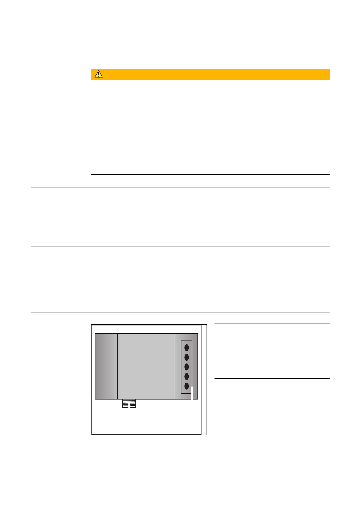
Généralités
(2)
(1)
Sécurité
Principes fondamentaux
AVERTISSEMENT!
Danger dû à un mauvais fonctionnement et à un travail mal effectué.
De graves blessures aux personnes et des dommages aux biens peuvent en résulter.
Tous les travaux décrits dans les présentes instructions de service ne doivent
▶
être effectuées que par un personnel qualifié.
Toutes les fonctions décrites dans les présentes instructions de service ne
▶
doivent être mises en oeuvre que par un personnel qualifié.
N’exécuter les travaux décrits ne mettre en oeuvre les fonctions décrites que
▶
lorsque tous les documents suivants ont été entièrement lus et compris :
les présentes instructions de service
▶
toutes les instructions de service des composants périphériques, en particu-
▶
lier les consignes de sécurité
Profibus est un concepteur de norme indépendante et ouverte de bus de terrain
pour diverses applications dans l’automatisation de la fabrication, des processus
et des constructions. Profibus est adapté aussi bien aux transmissions de
données rapides et critiques en termes de temps qu’aux tâches de communication étendues et complexes.
Conception de
l’appareil
Raccordements
avec l’interface Série d’appareils
TS/TPS, MW/TT
Le Profibus se distingue par un volume de construction peu encombrant et une
grande modularité.
Son montage simple et économe en place sur un rail normalisé C et le câblage
direct des acteurs et des capteurs sans raccordement croisé entre les bornes
normalise l’installation. De plus, le plan de marquage uniforme facilite l’installation.
(1) Anti-traction avec passages de
câbles
pour le passage du câble de
données Profibus et de l’alimentation électrique du coupleur de bus de terrain
(2) Connexion LocalNet
pour le branchement du faisceau de liaison.
74
Page 75

Consignes sup-
(1) (2)
(3)
(4)
(5)
(6) (7)
(8)
(9)
(10)
plémentaires
Exemple d’utilisation - Série
d’appareils TS/
TPS, MW/TT
REMARQUE ! Tant que l’interface robot est connectée au LocalNet, le mode de
service « Mode 2 temps » reste automatiquement sélectionné (affichage : Mode 2
temps).
Vous trouverez des informations plus détaillées concernant le mode de soudage « Mode 2 temps spécial pour interface robot » dans les chapitres « Soudage
MIG/MAG » et « Paramètres Mode de service » des Instructions de service de la
source de courant.
FR
Remarques relatives au montage
de la variante externe de l’interface
(1) Source de courant
(2) Refroidisseur
(3) Profibus
(4) Faisceau de liaison
(5) Câble de données Profibus
REMARQUE ! Lors du montage de la variante externe de l’interface, respecter les
prescriptions suivantes :
La pose des câbles doit s’effectuer séparément des lignes affectées au
-
réseau d’alimentation
Le montage du coupleur de bus doit s’effectuer séparément des lignes af-
-
fectées au réseau d’alimentation ou des composants relié à ce dernier
Le coupleur de bus de terrain doit être installé dans un endroit protégé de la
-
saleté et de l’eau
Veiller à ce que la tension d’alimentation 24 V soit séparée des circuits élec-
-
triques d’une tension supérieure.
(6) Commande robot
(7) Pack Marathon
(8) Robot
(9) Torche de soudage
(10) Dévidoir-fil
75
Page 76

Raccorder et configurer le coupleur de bus de ter-
BK3120
BECKHOFF
(1)
(2)
(3)
rain
Sécurité
Éléments de
commande et
connecteurs
coupleur de bus
de terrain
AVERTISSEMENT!
Risque d'électrocution.
Cela peut entraîner des dommages corporels et matériels graves.
Avant d'entamer les travaux, déconnecter tous les appareils et composants
▶
concernés et les débrancher du réseau électrique.
S'assurer que tous les appareils et composants concernés ne peuvent pas
▶
être remis en marche.
Après ouverture de l'appareil, s'assurer, à l'aide d'un appareil de mesure ap-
▶
proprié, que les composants à charge électrique (condensateurs, par ex.)
sont déchargés.
(1) Connecteur Profibus
(2) Sélecteur d’adresse
(3) Connecteurs pour l’alimentati-
on électrique externe
IMPORTANT! L’alimentation électrique externe ne doit pas provenir de la
source de courant. Pour l’alimentation
électrique externe, utiliser le robot ou
la commande.
Raccorder et
configurer le
coupleur de bus
de terrain
76
ATTENTION!
Risque d'électrocution.
Cela peut entraîner de graves dommages matériels.
Avant le début des travaux, s’assurer que le câble pour l’alimentation électri-
▶
que externe de l’interface soit hors tension et le demeure pendant toute la
durée des travaux.
Page 77

Coupleur de bus de terrain monté sur un profilé chapeau isolé - Série d’appareils TS/TPS, MW/TT
3: RxD/TxD-P
5: DGND
8: RxD/TxD-N
6
1
IMPORTANT ! Pour le montage du coupleur de bus de terrain, utiliser exclusivement des rails profilés « isolés ». Vérifier que le rail profilé n’ait aucun contact
électrique avec la terre de la source de courant.
Démonter le couvercle de l’interface
1
Retirer l’anti-traction de l’interface
2
Passer le câble de données Profibus et le câble pour l’alimentation électrique
3
externe dans l’anti-traction par le passage pour câbles
Raccorder le câble de données
4
Profibus au connecteur Profibus
Raccorder l’alimentation électrique
5
externe du robot ou de la commande aux connecteurs pour l’alimentation électrique externe sur le
coupleur de bus de terrain
Monter le câble de données Profi-
6
bus et le câble pour l’alimentation
électrique externe à l’aide d’attache-câbles dans l’anti-traction par
le passage pour câbles
Monter l’anti-traction sur l’inter-
7
face avec le matériel de fixation
original de manière à ce que l’anti-
Plan de connexion Profibus
traction reprenne sa position initiale
FR
REMARQUE ! Possibilité de perturbation de la communication des données en
raison d’un défaut de liaison blindée. Veiller à ce que le blindage du câble soit bien connecté dans la prise aux deux extrémités.
IMPORTANT ! Avant la mise en service, vérifier si le blindage du côté du robot
est bien relié à la terre du robot.
Pour les systèmes comprenant plus de deux sources de courant, brancher les
sources de courant en parallèle.
REMARQUE ! Mettre en place des résistances aux extrémités du câble de bus de
terrain, afin d’éviter les réflexions et les problèmes de transmission qui y sont
liés.
77
Page 78

Source de courant 1
RxD/TxD-P (3)
DGND (5)
Source de courant 2
RxD/TxD-N (8)
RxD/TxD-P (3)
DGND (5)
RxD/TxD-N (8)
Rail de montage
Rail de montage
Blindage
Plan de connexion Profibus
0
1
2
3
4
5
6
7
8
9
0
1
2
3
4
5
6
7
8
9
x 1
x 10
Sur série d’appareils TS/TransPuls Synergic, MW/TT :
Raccorder la prise LocalNet du faisceau de liaison à la connexion Localnet
8
sur l’interface
Configuration
adresse esclave
Paramétrer l’adresse esclave à l’aide des deux sélecteurs rotatifs.
Paramétrage par défaut = 11
Toutes les adresses sont admises, mais chaque adresse ne peut apparaître qu’une
fois sur le réseau.
S’assurer que tous les appareils et composants concernés sont débranchés
1
du secteur et sont déconnectés.
S’assurer que l’interface est débranchée du secteur
2
À l’aide d’un tournevis, placer le commutateur dans la position souhaitée.
3
le commutateur supérieur est un multiplicateur d’unités
-
le commutateur supérieur est un multiplicateur de dizaines
-
Important ! S’assurer que le commutateur est bien enclenché.
Exemple
Régler l’adresse 34 :
Sélecteur rotatif supérieur : 4
-
Sélecteur rotatif inférieur : 3
-
Remonter le couvercle de l’interface avec les vis d’origine de manière à ce
4
que la couvercle de l’interface reprenne sa position initiale
78
Page 79

Propriétés de la transmission de données
Technique de
transmission RS
485
Topologie du réseau
Bus linéaire, fermeture active de bus aux deux extrémités, câbles de dérivation
possibles
Medium
Câble blindé torsadé, le blindage doit être exécuté.
Nombre de stations
32 stations dans chaque segment sans répéteur. Avec répéteurs, peut être augmenté jusqu’à 127.
Longueur max. du bus sans répéteur
100 m pour 12 MBit/s câble A : 200 m pour 1500 KBit/s, jusqu’à 1,2 km pour
93,75 KBit/s
Longueur max. du bus avec répéteur
Au moyen d’un répéteur de circuit (répéteur), la longueur maximum du bus
peut être augmentée jusqu’à un périmètre de 10 km. Le nombre de répéteurs
possibles est d’au moins 3 et peut monter jusqu’à 10 en fonction du fabricant.
Vitesse de transmission
9,6 ; 19,2 : 93,75 ; 187,5 ; 500 ; 1500 KBit/s, jusqu’à 12 MBit/s réglée automatiquement
Connecteur
Connecteur 9 broches D-Sub
Bande passante de données de processus
Profibus (4,100,231,4,100,233)
Twin Profibus (4,100,403)
112 Bit (configuration standard)
176 Bit (configuration standard)
FR
Réseaux LWL
Format de données de processus
Motorola
Topologie du réseau
Subring
Medium
APF (plastique) - fibres (Z1101)
Longueur min. / max. entre deux stations
Coordinateur - Station : L ≥ 1 m L ≤ 34 m
Station - Station : L ≥ 1 m L ≤ 25 m
Station - Coordinateur : L ≥ 0 m L ≤ 46 m
Nombre de stations
93,75 kBaud : 13 187,5 kBaud :
12
Vitesse de transmission
93,75 187,5 500 1500 KBit/s
500 kBaud :
12
1500 kBaud :
10
Position du commutateur
S1 = 0, S2 = 0 S1 = 0, S2 = 0 S1 = 0, S2 = 0 S1 = 0, S2 = 0
79
Page 80

Connexion bus
2 x HP Simplex
Dispositif de
sécurité
Bande passante de
données de processus
Profibus LWL (4,100,232) 112 Bit
Pour que la source de courant puisse interrompre le processus en cas d’absence
de transmission de données, le noeud du bus de terrain dispose d’une surveillance de mise hors circuit. Si aucune transmission de données n’a lieu dans un délai
de 700 ms, toutes les entrées et sorties sont remises à zéro et la source de courant se trouve à l’état „Stop“. Après la reprise de la transmission de données a
lieu la reprise du processus par les signaux suivants :
Signal “Robot ready”
-
Signal “Valider la panne”
-
80
Page 81

Diagnostic d’erreur, élimination de l'erreur
BK3120
BECKHOFF
(1)
(2)
(3)
Sécurité
Généralités
AVERTISSEMENT!
Risque d'électrocution.
Cela peut entraîner des dommages corporels et matériels graves.
Avant d'entamer les travaux, déconnecter tous les appareils et composants
▶
concernés et les débrancher du réseau électrique.
S'assurer que tous les appareils et composants concernés ne peuvent pas
▶
être remis en marche.
Après ouverture de l'appareil, s'assurer, à l'aide d'un appareil de mesure ap-
▶
proprié, que les composants à charge électrique (condensateurs, par ex.)
sont déchargés.
(1) Voyants DEL d’état de service
(2) Voyants DEL de statut du bus
(3) Voyants DEL d’alimentation
DEL gauche ... indique l’ali-
-
mentation du coupleur de
bus de terrain
DEL droite ... indique l’ali-
-
mentation des contacts
d’alimentation
FR
Voyants DEL
d’état de service
Code de clignotement
Si une erreur se produit, les voyants DEL de statut du bus et d’état de service signalent le type d’erreur et l’endroit où elle s’est produite.
IIMPORTANT ! Après élimination de l’erreur, dans de nombreux cas, la séquence
de clignotement ne se termine pas au niveau du coupleur de bus de terrain.
Redémarrer en éteignant et en rallumant l’alimentation électrique ou en réinitialisant le logiciel du coupleur de bus de terrain.
Les voyants DEL d’état de service indique la communication locale entre le coupleur de bus de terrain et les bornes du bus de terrain. La DEL verte s’allume si le
fonctionnement est normal. La DEL rouge clignote avec deux fréquences
différentes si une erreur de bus se produit.
81
Page 82

(a) (b) (c)
Clignotement rapide :
a)
Démarrage du code d’erreur
Première impulsion lente :
b)
Type d’erreur
Deuxième impulsion lente :
c)
Emplacement de l’erreur
IMPORTANT ! Le nombre d’impulsions
indique la position de la dernière borne
du bus de terrain avant la survenue de
l’erreur. Les bornes passives du bus de
terrain (par exemple bornes d’alimentation) ne sont pas incluses dans ce
nombre.
Code d’erreur
Clignotement immobile permanent
1 impulsion 0 impulsions Erreur du total de
Explication
de l’erreur Cause Remède
0 impulsions Problèmes de com-
patibilité électromagnétique (CEM)
contrôle EEPROM
1 impulsion Dépassement Inline-
Code- Buffer
Trop d’entrées dans
le tableau
Contrôler l’alimentation
électrique afin de
détecter les pics de
sous-tension ou de surtension
Appliquer les mesures
relatives à la compatibilité électromagnétique
En cas d’erreur de bus
de bornes, l’erreur peut
être localisée en
redémarrant (éteindre
et rallumer) le coupleur
de bus de terrain.
Mettre le réglage usine
avec le KS2000
Brancher moins de bornes
2 impulsions 0 impulsions Configuration pro-
3 impulsions 0 impulsions Erreur de commande
82
2 impulsions Type de données in-
connu
grammée
Entrée du tableau incorrecte / Coupleur
de bus
n impulsions
(n>0)
Comparaison tableau
borne(s) incorrecte
bus de bornes
Exécuter la mise à jour
du logiciel du coupleur
de bus de terrain
Vérifier l’exactitude de
la configuration programmée
Entrée du tableau incorrecte /Coupleur de
bus
Pas de borne branchée,
raccorder les bornes
Page 83

Code d’erreur
Une borne est défectu-
Explication
de l’erreur Cause Remède
euse
Dédoubler les bornesraccordées et vérifier si
l’erreur se produit également avec les bornes
restantes. Répéter la
procédure jusqu’à ce
que la borne défectueuse soit détectée.
FR
4 impulsions 0 impulsions Erreur de données
bus de bornes
5 impulsions n impulsions Erreur bus de bornes
9 impulsions 0 impulsions Erreur du total de
13 impulsions
n impulsions Interruption derrière
les bornes (0 : coupleur)
lors de la communication de registre
avec les bornes
contrôle dans Pro-
grammflash.
n impulsions La borne de bus n ne
correspond pas à la
configuration qui
existait au moment
du réglage du projet
d’amorçage.
0 impulsions Erreur de commande
durée de fonctionnement du bus de bornes
Vérifier si la borne n+1
est bien branchée, le
cas échéant remplacer
Vérifier si la borne terminale KL9010 est
branchée
Remplacer les bornes
Mettre le réglage usine
avec le KS 2000
Mettre le réglage usine
avec le KS 2000 pour
effacer le projet
d’amorçage
Une borne de bus est
défectueuse.
Dédoubler les bornes
de bus et vérifier la
présence d’erreurs sur
les autres bornes de
bus. Répéter la
procédure jusqu’à ce
que la borne de bus
défectueuse soit localisée.
14 impulsions
15 impulsions
n impulsions La borne de bus n a
un format incorrect
n impulsions Le nombre de bornes
de bus n’est plus
conforme
Redémarrer le coupleur ; si l’erreur se reproduit, remplacer la
borne de bus
Redémarrer le coupleur.
Si l’erreur se reproduit,
mettre le réglage usine
avec le KS 2000.
83
Page 84

Code d’erreur
Explication
de l’erreur Cause Remède
Voyants DEL de
statut du bus de
terrain
16 impulsions
17 impulsions
18 impulsions
Les voyants DEL de statut de bus de terrain indiquent les états de service du bus
de terrain. Les fonctions du Profibus sont restituées par les DEL „I/O RUN“, „BF“
et „DIA“.
n impulsions La longueur des
données du bus de
bornes (longueur de
bit) n’est plus conforme. n = longueur de
bit après démarrage
n impulsions Le nombre de bornes
de bus n’est plus
conforme. n =
nombre de bornes
après démarrage
n impulsions Après réinitialisation,
la désignation des
bornes de bus n’est
plus conforme. n =
numéro de borne de
bus
Redémarrer le coupleur.
Si l’erreur se reproduit,
mettre le réglage usine
avec le KS 2000.
Redémarrer le coupleur.
Si l’erreur se reproduit,
mettre le réglage usine
avec le KS 2000.
Redémarrer le coupleur.
Si l’erreur se reproduit,
mettre le réglage usine
avec le KS 2000.
I/O
RUN BF DIA Cause Remède
allumé éteint éteint État de service „RUN“
Les entrées sont lues et
les sorties émises
allumé allumé éteint,
clignote
éteint éteint éteint Cycle de bus de bornes
Activité du bus de terrain. L’esclave n’a pas
encore été paramétré
Les erreurs du bus de
terrain avec réaction
des sorties :
sont à 0
-
sont maintenues
-
synchrone avec DPWatchdog hors service,
par d’échange de
données
Fonctionnement conforme.
Aucun intervention requise.
Démarrer le maître
Vérifier les paramètres
(données de diagnostic,
DEL DIA)
Vérifier la configuration
(données de diagnostic,
DEL DIA)
Démarrer le maître
Vérifier les paramètres
(données de diagnostic,
DEL DIA)
Vérifier la configuration
(données de diagnostic,
DEL DIA)
SPS est sur „Stop“.
Démarrer SPS
84
éteint allumé allumé absence d’activité du
bus
Démarrer le maître
Vérifier le câble de bus
Page 85

I/O
RUN BF DIA Cause Remède
Erreur données
de configuration
Profibus
éteint allumé éteint,
clignote
Erreur lors de la montée en régime DP
Indication d’une erreur lors du paramétrage (UserPrmData) ou de la configuration (CfgData). Indication par les DEL du bus de terrain et les données de diagnostic (Diag-Data). Identification par code erreur et explication de l’erreur.
Erreur lors de la vérification des données UserPrmData
Code erreur 1
bit réservé dans UserPrmData réglé sur une valeur incorrecte
-
ou bien la fonction correspondante au bit dans UserPrmData n’est pas
-
compatible
L’explication de l’erreur décrit dans quel byte UserPrmData l’erreur a été
détectée (écart du byte erroné + 1).
Erreur du bus, réaction :
Le cycle du bus de bornes est interrompu
Démarrer le maître
Vérifier les paramètres
(données de diagnostic,
DEL DIA)
Vérifier la configuration
(données de diagnostic,
DEL DIA)
FR
Code erreur 3
une configuration de fonctions choisie n’est pas autorisée. Description par explication de l’erreur.
Explication de
l’erreur
1 En mode synchrone, le réglage de la réaction sur erreur DP
2 La liaison DPV1-MSAC-C1 a été activée par le maître, mais
6 Le mode Multi-Configurator n’est pas autorisé lorsque la véri-
8 Le mode synchrone ne peut être activé que si au moins un
10 Le cycle d’entrée optimisé est uniquement possible en mode
11 La longueur du DP-Buffer est supérieure à la taille de la DP-
12 Le mode Fast-FreeRun ne peut pas être activé en même
Description
sur „Sorties modifiées“ n’est pas autorisé.
aucune liaison DPV1-MSAC_C1 n’est définie
fication des données CfgData est hors service
byte de sortie DP est configuré
synchrone
RAM dans Profibus-Asic
temps que le mode synchrone
Erreur lors de la vérification des données CfgData
Code erreur 2
un byte n’est pas conforme dans CfgData. L’explication de l’erreur décrit dans
quel byte CfgData l’erreur a été détectée (écart du byte erroné + 1).
85
Page 86

Code erreur 5
La longueur de la sortie numérique (en bytes), calculée à partir des données
CfgData, n’est pas conforme. L’explication de l’erreur contient la longueur de
byte attendue.
Code erreur 6
La longueur de l’entrée numérique (en bytes), calculée à partir des données
CfgData, n’est pas conforme. L’explication de l’erreur contient la longueur de
byte attendue.
Code erreur 7
Indique différentes erreurs lors de la vérification des données CfgData. L’explication de l’erreur décrit l’erreur.
Explication de
l’erreur
1 La longueur des données CfgData reçues n’est pas conforme
2 La syntaxe des données CfgData reçues n’est pas conforme
3 La longueur des données d’entrée DP, calculée à partir des
4 La longueur des données de sortie DP, calculée à partir des
Erreur lors de la montée en régime de l’esclave
Code erreur 8
La longueur du DP-Buffer est supérieure à la taille de la DP-RAM dans Profibus-Asic. L’explication de l’erreur contient la différence (divisée par 8). Désactivation de la communication DP.
Code erreur 9
Indique différentes erreurs qui interviennent lors de la montée en régime de
l’appareil. L’explication de l’erreur décrit l’erreur.
Explication de
l’erreur
Description
données CfgData, est trop grande
données CfgData, est trop grande
Description
1 La longueur des données d’entrée DP est trop grande (trop
de modules connectés)
2 La longueur des données de sortie DP est trop grande (trop
de modules connectés)
3 La longueur des données CfgData est trop grande (trop de
modules connectés)
Réaction aux erreurs Profibus
Une erreur Profibus (panne du maître, retrait de la prise du Profibus, etc.) est
détectée par l’extinction du DP-Watchdog (en règle générale dans un délai de
100 ms, si ce maître n’a pas été désactivé) ou par un Timeout du bus (durée de
surveillance du taux de bauds réglée sur 10 s).
Régler la réaction aux données de sortie du coupleur dans les données UserPrmData :
Byte Bit Valeur Description
86
Page 87

10 0-1 00
bin
Réaction aux erreurs Profibus : Le cycle de bus
de bornes est abandonné (par défaut, les sorties
numériques sont sur 0, les sorties complexes
vont sur une valeur de remplacement projetée)
Codes de service
affichés
10 0-1 01
bin
Réaction aux erreurs Profibus : Les sorties du
bus de bornes sont sur 0
10 0-1 10
bin
Réaction aux erreurs Profibus : Les sorties du
bus de bornes restent inchangées
Vous trouverez une description détaillée des codes de service affichés au chapitre „Diagnostic et élimination des pannes“ du mode d’emploi de la source de courant.
FR
87
Page 88

Description des signaux Profibus/Twin Profibus
BK 3120
KL6021-0010
KL9010
Généralités Les descriptions de signaux suivantes s’appliquent à une interface avec une bor-
ne de communication KL 6021-0010 (exécution standard)
Il existe en plus la possibilité d’intégrer d’autres bornes supplémentaires dans
une interface robot. Le nombre est toutefois limité par la taille du boîtier.
IMPORTANT! En cas d’intégration d’autres bornes, le modèle de données du
processus est modifié.
Modes de service
de la source de
courant - Série
d’appareils TS/
TPS, MW/TT
Vue d’ensemble Le chapitre « Profibus/Twin Profibus » se compose des sections suivantes :
En fonction du mode de service sélectionné, l’interface Profibus/Twin Profibus
peut transmettre des signaux d’entrée et de sortie très différents.
Mode de service E05 E04 E03
Soudage MIG/MAG Synergic standard 0 0 0
Soudage MIG/MAG Synergic pulsé 0 0 1
Mode Job 0 1 0
Sélection de paramètres internes 0 1 1
Soudage TIG 1 1 0
CC / CV 1 0 1
Soudage manuel standard 1 0 0
CMT / Procédé spécial 1 1 1
Signaux d’entrée et de sortie pour MIG/MAG - Série d’appareils TS/
-
TPS,MW/TT
Signaux d’entrée et de sortie pour TIG - Série d’appareils TS/TPS,MW/TT
-
Signaux d’entrée et de sortie pour CC/CV - Série d’appareils TS/TPS,MW/TT
-
Signaux d’entrée et de sortie pour manuel standard - Série d’appareils TS/
-
TPS,MW/TT
Signaux d’entrée et de sortie pour Twin Profibus MIG/MAG - Série d’appa-
-
reils TS/TPS, MW/TT
88
Page 89

Signaux d’entrée et de sortie pour MIG/MAG Série d’appareils TS/TPS, MW/T
Signaux d’entrée
(du robot vers la
source de courant)
N° d’ordre Description du signal Plage Activité
E01 Gas Test - High
E02 Amenée de fil - High
E03 Retour de fil - High
E04 Valider la panne de source - High
E05 Recherche de position - High
E06 Soufflage torche - High
E07 Inutilisé - -
E08 Inutilisé - -
E09 Soudage activé - High
E10 Robot prêt - High
E11 Modes de service Bit 0 - High
E12 Modes de service Bit 1 - High
E13 Modes de service Bit 2 - High
E14 Identification maître Twin - High
E15 Inutilisé - -
FR
E16 Inutilisé - -
E17 - E23 Numéro de programme 0 - 127 -
E24 Simulation du soudage - High
E25 - E32 Numéro de tâche 0 - 99 -
Avec RCU 5000i et en mode de service Mode tâche
E17 - E23 Numéro de tâche 256 - 999 -
E24 Simulation du soudage - High
E25 - E32 Numéro de tâche 0 - 255 -
Valeur de consigne puissance 0 - 65535
(0 % - 100 %)
E33 - E40 High Byte - -
E41 - E48 Low Byte - -
Valeur de consigne correc-
tion
de la longueur de l’arc électrique
E49 - E56 High Byte - -
E57 - E64 Low Byte - -
0 - 65535
(-30 % - +30 %)
-
-
E65 - E72 Inutilisé - -
89
Page 90

N° d’ordre Description du signal Plage Activité
E73 - E80 Valeur de consigne brûlure
retour du fil
E81 - E88 Inutilisé - -
E89 - E96 Valeur de consigne correc-
tion
arc pulsé / dynamique
E97 Synchro Puls disable - High
E98 SFI disable - High
E99 Valeur de consigne correc-
tion
arc pulsé / dynamique disable
E100 Valeur de consigne brûlure
retour du fil disable
E101 Power Full Range (0 - 30 m) - High
E102 Inutilisé - -
E103 - E112 Vitesse de soudage 0 - 1023
0 - 255
(-200 ms - +200
ms)
0 - 255
(-5 % - +5 %)
- High
- High
(0 - 1023 cm/min)
-
-
-
Signaux de sortie (de la source
de courant vers
le robot)
N° d’ordre Description du signal Plage Activité
A01 - A08 Numéro d’erreur 0 - 255 High
A09 Arc électrique créé - High
A10 Signal limite (uniquement en
relation avec RCU 5000i)
A11 Processus actif - High
A12 Signal de courant principal - High
A13 Protection collision torche - High
A14 Source de courant prête - High
A15 Communication prête - High
A16 Réserve - -
A17 Contrôle collage du fil - High
A18 Inutilisé - -
A19 Accès robot (en relation avec
RCU 5000i)
A20 Fil disponible - High
A21 Durée dépassée court-circuit - High
- High
- High
90
A22 Données documentation
prêtes
A23 Inutilisé - -
A24 Puissance hors plage - High
- High
Page 91

N° d’ordre Description du signal Plage Activité
A25 - A32 Inutilisé - -
Valeur réelle tension de soudage
A33 - A40 High Byte - -
A41 - A48 Low Byte - -
Valeur réelle courant de soudage
A49 - A56 High Byte - -
A57 - A64 Low Byte - -
A65 - A72 Inutilisé - -
A73 - A80 Inutilisé - -
A81 - A88 Inutilisé - -
A89 - A96 Valeur réelle courant moteur 0 - 255
Valeur réelle dévidoir fil 0 - 65535
A97 - A104 High Byte - -
A105 - A112 Low Byte - -
0 - 65535
(0 - 100 V)
0 - 65535
(0 - 1000 A)
(0 - 5 A)
(-327,68 - +327,67
m/min)
-
-
FR
-
91
Page 92

Signaux d’entrée et de sortie pour TIG - Série
d’appareils TS/TPS, MW/TT
Signaux d’entrée
(du robot vers la
source de courant)
N° d’ordre Description du signal Plage Activité
E01 Gas Test - High
E02 Amenée de fil - High
E03 Retour de fil - High
E04 Valider la panne de source - High
E05 Recherche de position - High
E06 KD disable - High
E07 Inutilisé - -
E08 Inutilisé - -
E09 Soudage activé - High
E10 Robot prêt - High
E11 Modes de service Bit 0 - High
E12 Modes de service Bit 1 - High
E13 Modes de service Bit 2 - High
E14 Inutilisé - -
E15 Inutilisé - -
E16 Inutilisé - -
E17 DC / AC - High
E18 DC - / DC + - High
E19 Formation de calotte - High
E20 Impulsions disable - High
E21 Sélection plage d’impulsion
Bit 0
E22 Sélection plage d’impulsion
Bit 1
E23 Sélection plage d’impulsion
Bit 2
E24 Simulation du soudage - High
E25 - E32 Numéro de tâche 0 - 99 -
Valeur de consigne pour le
courant principal
E33 - E40 High Byte - -
E41 - E48 Low Byte - -
Valeur de consigne pa-
ramètre externe
- High
- High
- High
0 - 65535
(0 - I
0 - 65535 -
max
)
-
92
E49 - E56 High Byte - -
E57 - E64 Low Byte - -
Page 93

N° d’ordre Description du signal Plage Activité
E65 - E72 Inutilisé - -
Réglage de la
plage d’impulsion TIG
E73 - E80 Valeur de consigne Duty Cy-
cle
0 - 255
(10% - 90%)
-
E81 - E88 Inutilisé - -
E89 - E96 Valeur de consigne courant
de base
0 - 255
(0% - 100%)
-
E97 Inutilisé - -
E98 Inutilisé - -
E99 Courant de base disable - High
E100 Duty Cycle disable - High
E101 - E102 Inutilisé - -
E103 - E112 Valeur de consigne vitesse
d’avance fil
0 - 1023
(0 - vD
max
-
)
Fd.1
Mode de service E23 E22 E21
Régler la plage d’impulsion au
0 0 0
niveau de la source de courant
FR
Signaux de sortie (de la source
de courant vers
le robot)
Plage de réglage impulsion
0 0 1
désactivée
0,2 - 2 Hz 0 1 0
2 - 20 Hz 0 1 1
20 - 200 Hz 1 0 0
200 - 2000 Hz 1 0 1
N° d’ordre Description du signal Plage Activité
A01 - A08 Numéro d’erreur - High
A09 Arc électrique créé - High
A10 Inutilisé - -
A11 Processus actif - High
A12 Signal de courant principal - High
A13 Protection collision torche - High
A14 Source de courant prête - High
A15 Communication prête - High
A16 Réserve - -
A17 Inutilisé - -
A18 Haute fréquence active - High
A19 Inutilisé - -
93
Page 94

N° d’ordre Description du signal Plage Activité
A20 Fil disponible (fil froid) - High
A21 Inutilisé - -
A22 Inutilisé - -
A23 Puls High - High
A24 Inutilisé - -
A25 - A32 Inutilisé - -
Valeur réelle tension de soudage
A33 - A40 High Byte - -
A41 - A48 Low Byte - -
Valeur réelle courant de soudage
A49 - A56 High Byte - -
A57 - A64 Low Byte - -
A65 - A72 Inutilisé - -
A73 - A80 Valeur réelle longueur de
l’arc électrique (AVC)
A81 - A88 Inutilisé - -
A89 - A96 Valeur réelle courant moteur
(fil froid)
Valeur réelle vitesse d’avance
fil (fil froid)
A97 - A104 High Byte - -
0 - 65535
(0 - 100 V)
0 - 65535
(0 - 1000 A)
0 - 255 High
0 - 255
(0 - 5 A)
0 - 65535
(-327,68 - +327,67
m/min)
-
-
-
-
A105 - A112 Low Byte - -
94
Page 95

Signaux d’entrée et de sortie pour CC/CV - Série
d’appareils TS/TPS, MW/TT
Signaux d’entrée
(du robot vers la
source de courant)
N° d’ordre Description du signal Plage Activité
E01 Gas Test - High
E02 Amenée de fil - High
E03 Retour de fil - High
E04 Valider la panne de source - High
E05 Recherche de position - High
E06 Soufflage torche - High
E07 Inutilisé - -
E08 Inutilisé - -
E09 Soudage activé - High
E10 Robot prêt - High
E11 Modes de service Bit 0 - High
E12 Modes de service Bit 1 - High
E13 Modes de service Bit 2 - High
E14 Identification maître Twin - High
E15 Inutilisé - -
FR
E16 Inutilisé - -
E17 - E23 Numéro de programme 0 - 127 -
E24 Simulation du soudage - High
E25 - E32 Numéro de tâche 0 - 99 -
Avec RCU 5000i et en mode de service Mode tâche
E17 - E23 Numéro de tâche 256 - 999
E24 Simulation du soudage - High
E25 - E32 Numéro de tâche 0 - 255
Valeur de consigne
courant de soudage
E33 - E40 High Byte - -
E41 - E48 Low Byte - -
Valeur de consigne
vitesse d’avance du fil
E49 - E56 High Byte - -
E57 - E64 Low Byte - -
E65 - E72 Inutilisé - -
0 - 65535
(0 - I
max
0 - 65535
(0,5 - vD
)
max
-
-
)
E73 - E80 Inutilisé - -
E81 - E88 Inutilisé - -
95
Page 96

N° d’ordre Description du signal Plage Activité
Signaux de sortie (de la source
de courant vers
le robot)
E89 - E96 Valeur de consigne
tension de soudage
E97 Synchro Puls disable - High
E98 SFI disable - High
E99 Tension de soudage disable - High
E100 Inutilisé - -
E101 Power Full Range (0 - 30 m) - High
E102 Inutilisé - -
E103 - E112 Vitesse de soudage 0 - 1023
N° d’ordre Description du signal Plage Activité
A01 - A08 Numéro d’erreur - High
A09 Arc électrique créé - High
A10 Signal limite
(uniquement en relation avec
RCU 5000i)
0 - 255
(0 - 50 V)
(0 - 1023 cm/min)
- High
-
-
A11 Processus actif - High
A12 Signal de courant principal - High
A13 Protection collision torche - High
A14 Source de courant prête - High
A15 Communication prête - High
A16 Réserve - -
A17 Contrôle collage du fil - High
A18 Inutilisé - -
A19 Accès robot (en relation avec
RCU 5000i)
A20 Fil disponible - High
A21 Durée dépassée court-circuit - High
A22 Données documentation
prêtes
A23 Inutilisé - -
A24 Puissance hors plage - High
A25 - A32 Inutilisé - -
- High
- High
96
Valeur réelle tension de soudage
A33 - A40 High Byte - -
A41 - A48 Low Byte - -
Valeur réelle courant de soudage
0 - 65535
(0 - 100 V)
0 - 65535
(0 - 1000 A)
-
-
Page 97

Signaux d’entrée et de sortie pour Manuel standard - Série d’appareils TS/TPS, MW/TT
Signaux d’entrée
(du robot vers la
source de courant)
N° d’ordre Description du signal Plage Activité
E01 Gas Test - High
E02 Amenée de fil - High
E03 Retour de fil - High
E04 Valider la panne de source - High
E05 Recherche de position - High
E06 Soufflage torche - High
E07 Inutilisé - -
E08 Inutilisé - -
E09 Soudage activé - High
E10 Robot prêt - High
E11 Modes de service Bit 0 - High
E12 Modes de service Bit 1 - High
E13 Modes de service Bit 2 - High
E14 Identification maître Twin - High
E15 Inutilisé - -
FR
E16 Inutilisé - -
E17 - E23 Numéro de programme 0 - 127 -
E24 Simulation du soudage - High
E25 - E32 Numéro de tâche 0 - 99 -
Avec RCU 5000i et en mode de service Mode tâche
E17 - E23 Numéro de tâche 256 - 999 -
E24 Simulation du soudage - High
E25 - E32 Numéro de tâche 0 - 255 -
Valeur de consigne
vitesse d’avance du fil
E33 - E40 High Byte - -
E41 - E48 Low Byte - -
Valeur de consigne
tension de soudage
E49 - E56 High Byte - -
E57 - E64 Low Byte - -
E65 - E72 Inutilisé - -
0 - 65535
(0,5 - vD
0 - 65535
(10 - 40 V)
max
-
)
-
E73 - E80 Valeur de consigne brûlure
retour du fil
0 - 255
(-200 ms - +200
ms)
-
97
Page 98

N° d’ordre Description du signal Plage Activité
E81 - E88 Inutilisé - -
Signaux de sortie (de la source
de courant vers
le robot)
E89 - E96 Valeur de consigne correc-
tion
arc dynamique
E97 Synchro Puls disable - High
E98 SFI disable - High
E99 Correction arc dynamique
disable
E100 Valeur de consigne brûlure
retour du fil disable
E101 Power Full Range (0 - 30 m) - High
E102 Inutilisé - -
E103 - E112 Vitesse de soudage 0 - 1023
N° d’ordre Description du signal Plage Activité
A01 - A08 Numéro d’erreur - High
A09 Arc électrique créé - High
0 - 255
(0 - 10)
- High
- High
(0 - 1023 cm/min)
-
-
A10 Signal limite
(uniquement en relation avec
RCU 5000i)
A11 Processus actif - High
A12 Signal de courant principal - High
A13 Protection collision torche - High
A14 Source de courant prête - High
A15 Communication prête - High
A16 Réserve - -
A17 Contrôle collage du fil - High
A18 Inutilisé - -
A19 Accès robot (en relation avec
RCU 5000i)
A20 Fil disponible - High
A21 Durée dépassée court-circuit - High
A22 Données documentation
prêtes
A23 Inutilisé - -
- High
- High
- High
98
A24 Puissance hors plage - High
A25 - A32 Inutilisé - -
Valeur réelle tension de soudage
A33 - A40 High Byte - -
0 - 65535
(0 - 100 V)
-
Page 99

N° d’ordre Description du signal Plage Activité
A41 - A48 Low Byte - -
Valeur réelle courant de soudage
0 - 65535
(0 - 1000 A)
-
FR
99
Page 100

Description de signal Twin Profibus pour
MIG/MAG - Série d’appareils TS/TPS,MW/TT
Signaux d’entrée
(du robot vers la
source de courant)
N° d’ordre Description du signal Plage Activité
E01 Soudage activé - High
E02 Robot prêt - High
E03 Modes de service Bit 0 - High
E04 Modes de service Bit 1 - High
E05 Modes de service Bit 2 - High
E06 Identification maître
Twin Source de courant 1
E07 Identification maître
Twin Source de courant 2
E08 Inutilisé - -
E09 Gas Test - High
E10 Amenée de fil - High
E11 Retour de fil - High
E12 Valider la panne de source - High
E13 Recherche de position - High
E14 Soufflage torche - High
- High
- High
E15 Inutilisé - -
E16 Inutilisé - -
E17 - E24 Numéro de tâche 0 - 99 -
E25 - E31 Numéro de programme 0 - 127 -
E32 Simulation du soudage - High
Avec RCU 5000i et en mode de service Mode tâche
E17 - E31 Numéro de tâche 0 - 999 -
E32 Simulation du soudage - High
E33 - E48 Valeur de consigne puissance
source de courant 1
E49 - E64 Valeur de consigne correc-
tion de la longueur de l’arc
électrique
source de courant 1
E65 - E72 Valeur de consigne correc-
tion arc pulsé / dynamique
source de courant 1
E73 - E80 Valeur de consigne brûlure
retour du fil
source de courant 1
0 - 65535
(0 - 100 %)
0 - 65535
(-30 % - +30 %)
0 - 255
(-5 % - +5 %)
0 - 255
(-200 - +200 ms)
-
-
-
-
100
E81 - E88 Inutilisé - -
E89 - E96 Inutilisé - -
 Loading...