

Page 1

/ Perfect Charging / Perfect Welding / Solar Energy
Roboterinterface EtherCAT DPS
EtherCAT DPS robot interface
Bedienungsanleitung
DEEN
Plasma
Operating Instructions
Plasma
42,0410,2368 001-20072017
Page 2

2
Page 3

Sehr geehrter Leser
Einleitung Wir danken Ihnen für Ihr entgegengebrachtes Vertrauen und gratulieren Ihnen zu Ihrem
technisch hochwertigen Fronius Produkt. Die vorliegende Anleitung hilft Ihnen, sich mit
diesem vertraut zu machen. Indem Sie die Anleitung sorgfältig lesen, lernen Sie die vielfältigen Möglichkeiten Ihres Fronius Produktes kennen. Nur so können Sie seine Vorteile
bestmöglich nutzen.
Bitte beachten Sie auch die Sicherheitsvorschriften und sorgen Sie so für mehr Sicherheit
am Einsatzort des Produktes. Sorgfältiger Umgang mit Ihrem Produkt unterstützt dessen
langlebige Qualität und Zuverlässigkeit. Das sind wesentliche Voraussetzungen für hervorragende Ergebnisse.
DE
3
Page 4

4
Page 5

Inhaltsverzeichnis
Allgemeines ............................................................................................................................................... 7
Sicherheit.............................................................................................................................................. 7
Gerätekonzept ...................................................................................................................................... 7
Anschlüsse am Interface....................................................................................................................... 7
Feldbus-Koppler anschließen und konfigurieren ....................................................................................... 8
Sicherheit.............................................................................................................................................. 8
Allgemeines .......................................................................................................................................... 8
Anschlüsse am Feldbus-Koppler BK1120 ............................................................................................ 8
EtherCAT Kabel und Steckverbinder.................................................................................................... 9
Feldbus-Koppler anschließen und konfigurieren ..................................................................................9
Netzkabel am Stecker anschließen ...................................................................................................... 10
Fehlerdiagnose, Fehlerbehebung .............................................................................................................. 11
Sicherheit.............................................................................................................................................. 11
Anzeigen am Feldbus-Koppler BK1120................................................................................................ 11
LEDs zur Diagnose der Spannugsversorgung...................................................................................... 11
LEDs zur Diagnose der EtherCAT State Machine/PLC........................................................................ 12
LEDs zur Feldbus-Diagnose................................................................................................................. 12
LEDs zur Diagnose des K-Bus ............................................................................................................. 13
Eigenschaften der Datenübertragung und technische Daten .................................................................... 15
Eigenschaften der Datenübertragung................................................................................................... 15
Sicherheitseinrichtung........................................................................................................................... 15
Technische Daten des Feldbus-Kopplers BK1120 ............................................................................... 16
Signalbeschreibung EtherCAT................................................................................................................... 17
Allgemeines .......................................................................................................................................... 17
Eingangssignale.................................................................................................................................... 17
Ausgangssignale................................................................................................................................... 18
DE
5
Page 6

6
Page 7

Allgemeines
DE
Sicherheit
Gerätekonzept Das Roboterinterface EtherCat DPS ist eine Schnittstelle zum Anbinden der Plasma-
Stromquelle DPS 2500 an eine Robotersteuerung. Die Ein- und Ausgangssignale werden
über eine EtherCAT-Datenleitung zwischen Interface und Robotersteuerung übertragen.
Das Roboterinterface EtherCat DPS ist bereits an der Stromquelle montiert und angeschlossen. Es ist lediglich notwendig, die Datenleitung und das Netzkabel am Interface anzuschließen.
WICHTIG! Um allfällige Störungen zu vermeiden, die Länge der Datenleitung zwischen Interface und Robotersteuerung möglichst kurz halten.
WARNUNG! Fehlbedienung und fehlerhaft durchgeführte Arbeiten können
schwerwiegende Personen- und Sachschäden verursachen. Die in dieser Anleitung beschriebenen Arbeiten erst dann durchführen, wenn Sie folgende Dokumente vollständig gelesen und verstanden haben:
- Diese Bedienungsanleitung
- Die Bedienungsanleitung der Stromquelle, insbesondere das Kapitel „Sicherheitsvorschriften“
- Sämtliche Bedienungsanleitungen der gesamten Anlage.
WARNUNG! Fehlerhaft durchgeführte Arbeiten können schwerwiegende Personen- und Sachschaden verursachen. Die in dieser Anleitung beschriebenen Arbeiten dürfen nur von geschultem Fachpersonal durchgeführt werden!
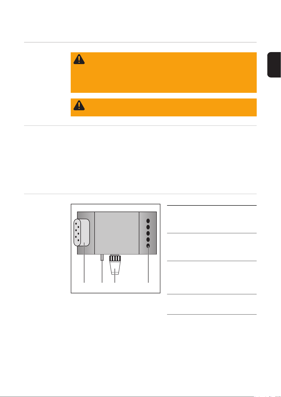
Anschlüsse am
Interface
(1) Zugentlastung
zum Durchführen der Datenleitung
EtherCat und der Spannungsversorgung für den Feldbus-Kopplers
(2) LocalNet-Anschluss mit Ab-
schluss-Stecker
für Software-Updates und Diagnosezwecke
(3) Schutzleiterkontakt
zum Anschließen zusätzlicher Optionen an den Schutzleiter der
(1)(2)(3)(4)
(4) Stecker Netzkabel
Stromquelle
(z.B. Fahrwagen, Lichtbogen-Abschaltbox, etc.)
zum Anschließen der Stromquelle
an das 400 V Netz
7
Page 8

Feldbus-Koppler anschließen und konfigurieren
Sicherheit
Allgemeines Das Anschließen des Interface EtherCAT erfolgt am Feldbus-Koppler BK1120.
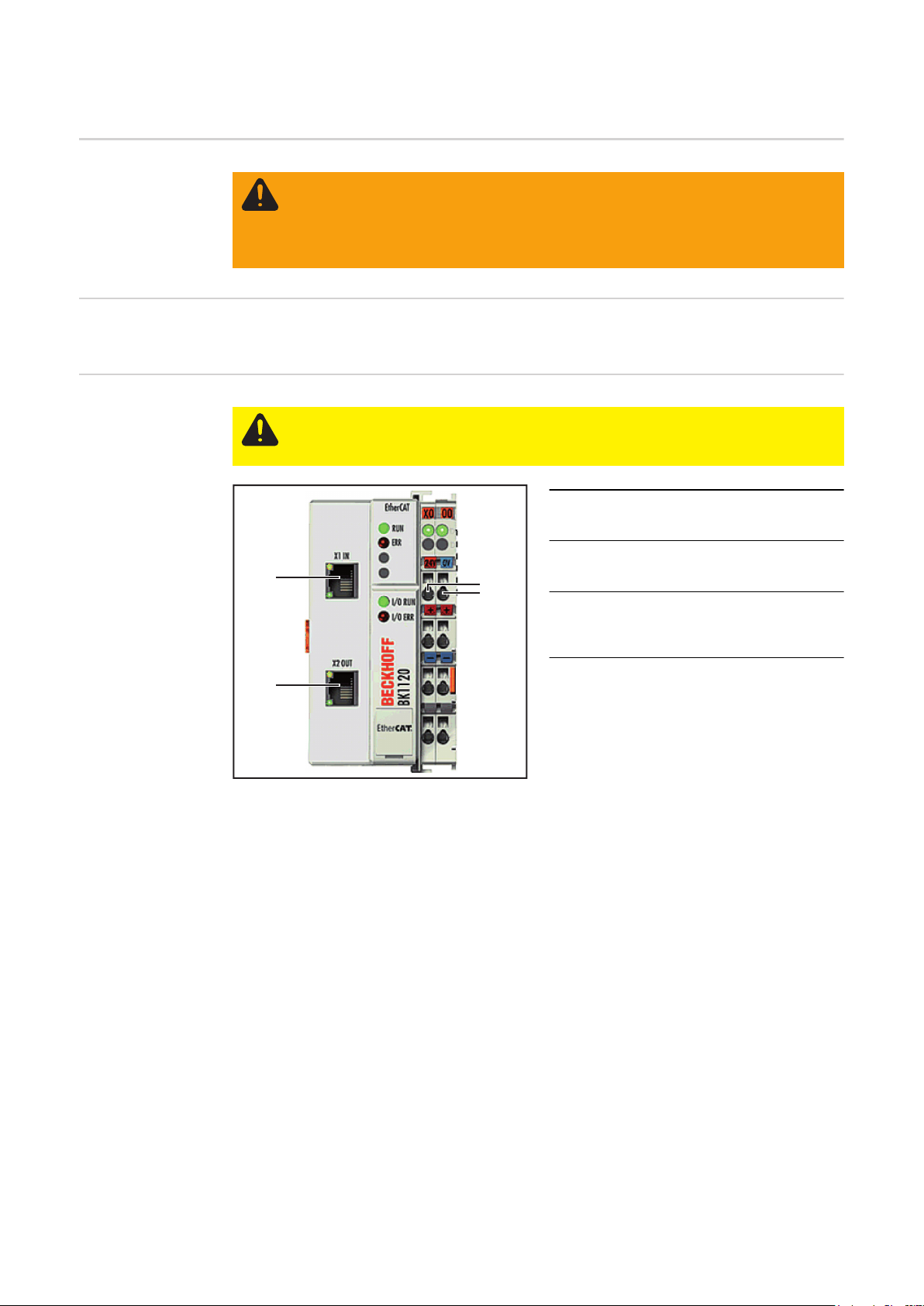
Anschlüsse am
Feldbus-Koppler
BK1120
WARNUNG! Ist die Anlage während der Inbetriebnahme mit dem Stromnetz ver-
bunden, besteht die Gefahr schwerwiegender Personen- und Sachschäden.
Sämtliche Arbeitsschritte nur durchführen, wenn
- der Netzschalter der Stromquelle in Stellung - O - geschaltet ist,
- die Anlage vom Stromnetz getrennt ist.
VORSICHT! Gefahr von Sachschäden. Vor Beginn der Arbeiten sicherstellen,
dass die Kabel für die externe Spannungsversorgung des Interfaces spannungsfrei sind und bis zum Abschluss aller Arbeiten spannungsfrei bleiben.
(1) Anschluss EtherNet RJ 45 - X1 IN
(2) Anschluss EtherNet RJ 45 - X2
(1)
(3)
(3) Anschlüsse DC IN
OUT
zum Anschließen der externen
Spannungsversorgung
(2)
8
Page 9

EtherCAT Kabel
und Steckverbinder
Verwenden Sie zur Verbindung von EtherCAT-Geräten nur Ethernet-Kabel, die mindestens der Kategorie 5 (CAt5) nach EN 50173 bzw. ISO/IEC 11801 entsprechen. EtherCAT
nutzt 4 Adern des Kabels für die Signalübertragung.
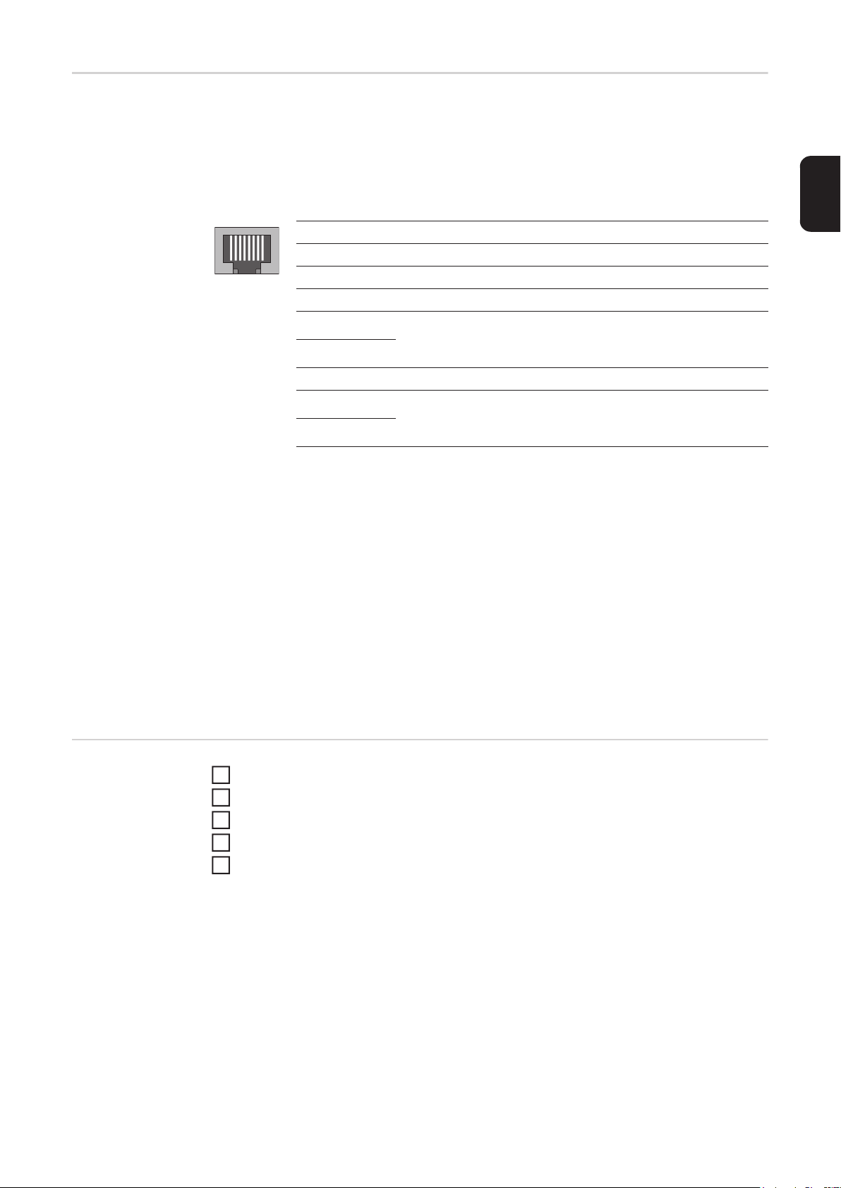
EtherCAT verwendet RJ45-Steckverbinder. Die Kontaktbelegung ist zum Ethernet-Standard (ISO/IEC 8802-3) kompatibel.
Pin Farbe Anmerkung
1 gelb TD+ (Transmission Data Pluspol)
18
2 orange TD- (Transmission Data Minuspol)
3 weiß RD+ (Receiver Data Pluspol)
4 - Normalerweise nicht verwendet; um die Signalvollständig-
5-
keit sicherzustellen, sind diese Pins miteinander verbun-
den und enden über einen Filterkreis am Schutzleiter (PE).
6 blau RD- (Receiver Data Minuspol)
7 - Normalerweise nicht verwendet; um die Signalvollständig-
8-
keit sicherzustellen, sind diese Pins miteinander verbun-
den und enden über einen Filterkreis am Schutzleiter (PE).
Aufgrund der automatischen Kabelerkennung (Auto-Crossing) können Sie zwischen
EtherCAT- Geräten von Beckhoff sowohl symmetrisch (1:1) belegte, wie auch
Cross-Over-Kabel verwenden.
DE
Feldbus-Koppler
anschließen und
konfigurieren
Die folgenden Beckhoff-Kabel und Steckverbinder sind für den Einsatz an EtherCAT-Systemen geeignet:
- ZB9010 (Industrial-Ethernet/EtherCAT-Kabel, feste Verlegung CAT 5e, 4-adrig)
- ZB9020 (Industrial-Ethernet/EtherCAT-Kabel schleppkettentauglich CAT 5e, 4-adrig)
- ZS1090-0003 (RJ45-Stecker, 4-polig, IP 20, feldkonfektionierbar)
- ZS1090-0005 (RJ45 Stecker, 8-polig (GigaBit geeignet), IP 20, feldkonfektionierbar)
- ZK1090-9191-0001 (0.17m EtherCAT Patch-Kabel)
- ZK1090-9191-0005 (0.5m EtherCAT Patch-Kabel)
- ZK1090-9191-0010 (1.0m EtherCAT Patch-Kabel)
- ZK1090-9191-0020 (2.0m EtherCAT Patch-Kabel)
- ZK1090-9191-0030 (3.0m EtherCAT Patch-Kabel)
- ZK1090-9191-0050 (5.0m EtherCAT Patch-Kabel)
Zugentlastung abnehmen und Kabel durchführen
1
Kabel mittels Kabelbindern an der Zugentlastung montieren
2
Externe Spannungsversorgung am Feldbus-Koppler anschließen
3
Datenleitung am Anschluss-Stecker anschließen
4
Zugentlastung montieren
5
9
Page 10

Netzkabel am Stecker anschließen
Interface und Stromquelle sind für die am
Leistungsschild angegebene Netzspannung ausgelegt.
Sind Netzkabel oder Netzstecker bei Ihrer
Geräteausführung nicht angebracht, müssen diese den nationalen Normen entsprechend montiert werden.
Die Absicherung der Netzzuleitung den
Technischen Daten entnehmen.
L1 L2 L3
Belegung Stecker Netzkabel
VORSICHT! Nicht ausreichend dimensionierte Elektroinstallation
kann zu schwerwiegenden Sachschäden führen.
Netzstecker, Netzzuleitung sowie
deren Absicherung sind entsprechend auszulegen.
10
Page 11

Fehlerdiagnose, Fehlerbehebung
DE
Sicherheit
Anzeigen am
Feldbus-Koppler
BK1120
WARNUNG! Ein elektrischer Schlag kann tödlich sein. Vor Beginn von Arbeiten
am Interface alle beteiligten Geräte und Komponenten
- ausschalten
- vom Netz trennen
- gegen Wiedereinschalten sichern.
(1)
(2)
(3)
(4)
(5)
(6)
(7)
(8)
(9)
(10)
LEDs zur Diagnose der Spannugsversorgung
(1) LED Run grün
(2) LED Error rot
(3) LED Link (X1 IN) gelb
(4) LED Aktiv (X1 IN) grün
(5) LED Link (X2 OUT) gelb
(6) LED Aktiv (X2 OUT) grün
(7) LED Power Supply grün
(8) LED Power Contacts grün
(9) LED I/O Run grün
(10) LED I/O Error rot
LED Anzeige Bedeutung
Power Supply Aus Keine Betriebsspannung am Buskoppler vorhanden
Leuchtet 24 VDC Betriebsspannung am Buskoppler vorhan-
Power Contacts Aus Keine Spannungsversorgung an den Powerkontak-
Leuchtet Spannungsversorgung 24 VDC an den Powerkontak-
zur Diagnose der EtherCAT State Machine/
PLC
zur Feldbus-Diagnose
zur Diagnose der Spannungsversorgung
zur Diagnose des K-Bus
den
ten vorhanden
ten vorhanden
11
Page 12

LEDs zur Diagnose der EtherCAT
State Machine/
PLC
LED Anzeige Bedeutung
Run Aus Der Buskoppler ist im Initialisierungs-Zustand
Blinkt Der Buskoppler ist im Zustand Pre-Operational
Einzelblitz Der Buskoppler ist im Zustand Safe-Operational
Leuchtet Der Buskoppler ist im Zustand Operational
Flackert Es wird eine Firmware geladen.
Error Aus Kein Fehler
Blinkt PLC-Fehler / Lost Frames
LEDs zur Feldbus-Diagnose
LED Anzeige Bedeutung
Link (X1 IN) Aus keine Verbindung auf dem ankommenden EtherCAT-
Strang
Leuchtet vorhergehender EtherCAT-Teilnehmer angeschlos-
sen
Aktiv (X1 IN) Blinkt Kommunikation mit vorhergehendem EtherCAT-
Teilnehmer
Aus keine Verbindung auf dem ankommenden EtherCAT-
Strang
Leuchtet keine Kommunikation auf dem ankommenden Ether-
CAT- Strang
Link (X2 OUT) Aus keine Verbindung auf dem weiterführenden Ether-
CAT- Strang
Leuchtet folgender EtherCAT-Teilnehmer angeschlossen
Aktiv (X2 OUT) Blinkt Kommunikation mit nachfolgendem EtherCAT- Teil-
nehmer
Aus keine Verbindung auf dem weiterführenden Ether-
CAT- Strang
Leuchtet keine Kommunikation auf dem weiterführenden
EtherCAT-Strang
12
Page 13

LEDs zur Diagnose des K-Bus
LED Anzeige Bedeutung Abhilfe
I/O Run Aus K-Bus inaktiv -
Leuchtet K-Bus aktiv -
I/O Error
Fehler-
Anzeige
Blinkt EMV Probleme - Spannungsversorgung
1 Implus 0 EEPROM-Prüfsum-
2 Impluse 0 Programmierte Kon-
3 Impulse 0 K-Bus-Kommando-
4 Impulse 0 K-Bus-Datenfehler,
5 Impulse n K-Bus-Fehler bei Re-
argument Bedeutung Abhilfe
auf Unter- oder Überspannungsspitzen kontrollieren
- EMV-Maßnahmen ergreifen
- Liegt ein K-Bus-Fehler
vor, kann durch erneutes
Starten (Aus- und Wiedereinschalten des Koppler) der Fehler lokalisiert
werden
Herstellereinstellung mit der
menfehler
1 Überlauf im Code
Buffer
2 Unbekannter Daten-
typ
figuration, falscher
Tabelleneintrag
n
(n > 0)
n Bruchstelle hinter
Tabellenvergleich
(Busklemme n)
fehler
Bruchstelle hinter
dem Buskoppler
Busklemme n
gister-Kommunikation mit Busklemme n
Konfigurationssoftware
KS2000 setzen (Menü "Online -> Koppler -> Dienste ->
Herstellereinstellung")
Weniger Busklemmen stecken. Bei prog. Konfiguration
sind zu viele Einträge in der
Tabelle
Software Update des Buskopplers notwendig
Programmierte Konfiguration
auf Richtigkeit überprüfen
Falscher Tabelleneintrag
- Keine Busklemme gesteckt
- Eine der Busklemmen ist
defekt; angehängte Busklemmen halbieren und
prüfen ob der Fehler bei
den übrigen Busklemmen
noch vorhanden ist. Dies
weiter durchführen, bis
die defekte Busklemme
lokalisiert ist.
Prüfen ob die n+1 Busklemme
richtig gesteckt ist, gegebenenfalls tauschen
Kontrollieren ob die Busendklemme 9010 gesteckt ist
n-te Busklemme tauschen
DE
13
Page 14

I/O Error
Fehler-
Anzeige
14 Impulse nn-te Busklemme hat
15 Impulse n Anzahl der Busklem-
16 Impulse n Länge der K-Bus-Da-
argument Bedeutung Abhilfe
das falsche Format
men stimmt nicht
mehr
ten stimmt nicht
mehr
Buskoppler erneut Starten,
falls der Fehler erneut auftritt
die Busklemme tauschen.
Buskoppler erneut Starten,
falls der Fehler erneut auftritt,
Herstellereinstellung mit der
Konfigurationssoftware
KS2000 setzen
Buskoppler erneut Starten,
falls der Fehler erneut auftritt,
Herstellereinstellung mit der
Konfigurationssoftware
KS2000 setzen
14
Page 15

Eigenschaften der Datenübertragung und technische Daten
Eigenschaften
der Datenübertragung
Sicherheitseinrichtung
DE
Übertragungstechnik EtherCAT
Netzwerk Topologie Stern / Linie
Medium Twistet-Pair-Kabel
Übertragungsrate 100 Mbit/s
Busanschluss EtherNet RJ 45
Prozessdaten-Breite 296 Bit (Standardkonfiguration)
Prozessdaten-Format Intel
Bei ausgefallener Datenübertragung werden alle Ein- und Ausgänge zurückgesetzt und
die Stromquelle befindet sich im Zustand „Stop“. Nach wiederhergestellter Datenübertragung erfolgt die Wiederaufnahme des Vorganges durch folgende Signale:
- Signal „Roboter ready“
- Signal „Quellen-Störung quittieren“
HINWEIS! Der Ausfall der Datenübertragung kann nur dann festgestellt werden,
wenn im Sync-Manager der Watchdog konfiguriert ist.
15
Page 16

Technische Daten
des FeldbusKopplers BK1120
Anzahl der K-Busklemmen 64
Max. Byte-Anzahl Feldbus 1024 Byte Input / Output
Digitale Peripheriesignale 8192 Inputs / Outputs
Analoge Peripheriesignale 256 Inputs / Outputs
Protokolle EtherCAT (Direct-Mode)
Baudrate 100 MBaud
Konfiguration Konfigurations-Software KS2000, TwinCAT Sys-
tem Manager oder via EtherCAT (ADS)
Busanschluss 2 x RJ45
Spannungsversorgung 24 VDC (-15%/+20%)
Stromaufnahme ca. 100 mA
Potenzialtrennung 500 V
eff
(Powerkontakt / Versorgungsspannung / Ether-
net)
zulässige Umgebungstemperatur im
0°C bis + 55°C
Betrieb
zulässige Umgebungstemperatur bei
-25°C bis + 85°C
Lagerung
zulässige relative Luftfeuchtigkeit 95%, keine Betauung
Abmessungen (B x H x T) ca. 49 mm x 100 mm x 70 mm
Montage auf 35 mm Tragschiene nach EN 50022
Vibrations- / Schockfestigkeit gemäß EN 60068-2-6 / EN 60068-2-27,
EN 60068-2-29
EMV-Festigkeit / Aussendung gemäß EN 61000-6-2 / EN 61000-6-4
Schutzart IP 20
Einbaulage beliebig
Zulassung CE, UL
16
Page 17

Signalbeschreibung EtherCAT
DE
Allgemeines
Eingangssignale Objekt 7000H RxPDO - Signale vom Roboter zur Stromquelle
Die folgenden Signalbeschreibungen gelten für ein Interface mit einer Kommunikationsklemme KL 6021-0010 (Standardausführung)
BK1120
KL6021-0010
Zusätzlich besteht die Möglichkeit, weitere Klemmen in ein Roboterinterface einzubauen.
Die Anzahl ist jedoch durch die Gehäusegröße limitiert.
HINWEIS! Beim Einbau weiterer Klemmen ändert sich das Prozess-Datenbild.
Je nach eingestellter Betriebsart kann das Interface EtherCAT verschiedene Ein- und Ausgangssignale übertragen.
Subindex
0H Anzahl der Einträge 0 - 255
1H 1H Prozess-Start High aktiv -
2H 1H Nicht in Verwendung - -
3H 1H - 8H reserviert - -
4H
5H 1H - 8H Zyklus-Dauer Low Low Byte
6H
Bit Signalbezeichnung Datentyp Bereich
2H Roboter bereit High aktiv 3H Nicht in Verwendung - 4H Nicht in Verwendung - 5H Nicht in Verwendung - 6H Nicht in Verwendung - 7H Nicht in Verwendung - 8H Nicht in Verwendung - -
2H Nicht in Verwendung - 3H Nicht in Verwendung - 4H Quellenstörung quittieren High aktiv 5H Nicht in Verwendung - 6H Toggling Bit High aktiv 7H Nicht in Verwendung - 8H Nicht in Verwendung - 9H - 16H reserviert - -
1H - 8H Strom-Sollwert Low Low Byte
9H - 16H Strom-Sollwert High High Byte
1H - 8H Zyklus-Dauer High High Byte
9H -16H Einschaltdauer Byte 0 - 100 %
KL9010
0 - 2500 dA
0 - 256 ms
17
Page 18

Subindex
7H 1H - 8H Pause Strom-Faktor Byte 0 - 100 %
8H
Ausgangssignale Objekt 6000H TxPDO - Signale von der Stromquelle zum Roboter
Bit Signalbezeichnung Datentyp Bereich
1H - 8H
9H - 16H
Slope Low
7H, 8H ... Slope Lower Bits
Slope High
9H - 16 H ... Slope Higher Bits
Low Byte -
High Byte 0 - 1023 A/ms
Subindex
0H Anzahl der Einträge 0 - 255
1H 1H Stromfluss High aktiv -
2H
3H 1H - 8H Plasma Betriebsstunden High High Byte
4H
5H 1H - 8H Strom-Istwert Low Low Byte
6H
7H 1H - 8H Betriebsstunden Low Low Byte 0 - 65535 h
8H 1H - 16H reserviert - 15H 1H - 8H reserviert - -
Bit Signalbezeichnung Datentyp Bereich
2H Toggling Bit High aktiv 3H Prozess aktiv High aktiv
4H Hauptstrom-Signal High aktiv
5H Nicht in Verwendung - 6H Stromquelle bereit High aktiv 7H Interface bereit High aktiv 8H Nicht in Verwendung - 1H - 8H Fehler-Nummer Byte 0 - 255
9H - 16H Plasma Betriebsstunden Low Low Byte
0 - 65535 h
1H - 8H Spannungs-Istwert Low Low Byte
0 - 999 dV
9H - 16H Spannungs-Istwert High High Byte
0 - 2500 dA
1H - 8H Strom-Istwert High High Byte
9H - 16H Betriebsstunden High High Byte 0 - 65535 h
18
Page 19

Dear reader,
Introduction Thank you for the trust you have placed in our company and congratulations on buying this
high-quality Fronius product. These instructions will help you familiarise yourself with the
product. Reading the instructions carefully will enable you to learn about the many different
features it has to offer. This will allow you to make full use of its advantages.
Please also note the safety rules to ensure greater safety when using the product. Careful
handling of the product will repay you with years of safe and reliable operation. These are
essential prerequisites for excellent results.
EN
19
Page 20

20
Page 21

Contents
General ...................................................................................................................................................... 23
Safety.................................................................................................................................................... 23
Device concept ..................................................................................................................................... 23
Interface connections............................................................................................................................ 23
Connecting and configuring the field bus coupler ...................................................................................... 24
Safety.................................................................................................................................................... 24
General ................................................................................................................................................. 24
Connections on the BK1120 field bus coupler...................................................................................... 24
EtherCAT cables and connectors ......................................................................................................... 25
Connecting and configuring the field bus coupler................................................................................. 25
Connecting the mains cable to the mains plug ..................................................................................... 26
Troubleshooting ......................................................................................................................................... 27
Safety.................................................................................................................................................... 27
Indications on the BK1120 field bus coupler......................................................................................... 27
LEDs for power supply diagnosis.......................................................................................................... 27
LEDs for EtherCAT State Machine/PLC diagnosis............................................................................... 28
LEDs for field bus diagnosis ................................................................................................................. 28
LEDs for K bus diagnosis...................................................................................................................... 29
Data transfer properties and technical data ............................................................................................... 31
Data transfer properties ........................................................................................................................ 31
Safety features...................................................................................................................................... 31
BK1120 field bus coupler technical data............................................................................................... 32
EtherCAT signal description ...................................................................................................................... 33
General ................................................................................................................................................. 33
Input signals.......................................................................................................................................... 33
Output signals....................................................................................................................................... 34
EN
21
Page 22

22
Page 23
General
Safety
Device concept The EtherCAT DPS robot interface is an interface for connecting the DPS 2500 plasma
power source to a robot control. The input and output signals are transferred between the
interface and robot control via an EtherCAT data cable.
The EtherCAT DPS robot interface is already fitted to the power source and connected.
Only the data cable and mains cable must be connected to the interface.
IMPORTANT! In order to avoid any interference, the length of the data cable between the
interface and the robot control must be kept as short as possible.
WARNING! Incorrect operation or poorly executed work can cause serious injury
or damage. Do not carry out any of the operations described in this manual until
you have completely read and understood the following documents:
- these Operating Instructions
- the power source Operating Instructions, particularly the chapter entitled
"Safety rules"
- all Operating Instructions for the complete system
WARNING! Work that is carried out incorrectly can cause serious injury or damage. The work described in these instructions must only be carried out by trained
personnel.
EN
Interface connections
(1) Strain-relief device
for the EtherCAT data line and the
power supply for the field bus coupler
(2) LocalNet connection with termi-
nating plug
for software updates and diagnosis
purposes
(3) Ground conductor contact
for connecting additional options to
the power source's ground conduc-
(1)(2)(3)(4)
(4) Mains cable plug
tor
(e.g. trolley, arc shut off box, etc.)
for connecting the power source to
the 400 V mains
23
Page 24
Connecting and configuring the field bus coupler
Safety
General The EtherCAT interface is connected to the BK1120 field bus coupler.
Connections on
the BK1120 field
bus coupler
WARNING! If the device is connected to the mains supply during commissioning,
there is a risk of serious injury and damage.
Only carry out these steps if
- the power source mains switch is in the "O" position
- the device is unplugged from the mains
CAUTION! Risk of damage. Before starting work ensure that the cable for the external power supply to the interface is de-energised and remains de-energised
until all work is complete.
(1) EtherNet RJ 45 connection - X1
IN
(2) EtherNet RJ 45 connection - X2
(1)
(3)
(3) DC IN connections
OUT
for connecting the external power
supply
(2)
24
Page 25
EtherCAT cables
and connectors
When connecting EtherCAT devices, use only Ethernet cables conforming to at least category 5 (CAt5), as defined in EN 50173 or ISO/IEC 11801. EtherCAT uses 4 cable conductors for signal transmission.
EtherCAT uses RJ45 connectors. Contact assignment is compatible with the Ethernet
standard (ISO/IEC 8802-3).
Pin Colour Remarks
1 yellow TD+ (Transmission Data positive pole)
18
2 orange TD- (Transmission Data negative pole)
3 white RD+ (Receiver Data positive pole)
4 - Not normally in use; to ensure signal integrity, these pins
5-
are connected to each other and terminate via a filter circuit
on the conductor (PE).
6 blue RD- (Receiver Data negative pole)
7 - Not normally in use; to ensure signal integrity, these pins
8-
are connected to each other and terminate via a filter circuit
on the conductor (PE).
Thanks to automatic cable detection (auto-crossing) you can use cables with a symmetrical pin-out (1:1), as well as cross-over -cables between Beckhoff EtherCAT devices.
EN
Connecting and
configuring the
field bus coupler
The following Beckhoff cables and connectors are suitable for use in EtherCAT systems:
- ZB9010 (Industrial Ethernet/EtherCAT cable, CAT 5e fixed installation, 4-core)
- ZB9020 (Industrial Ethernet/EtherCAT cable, CAT 5e suitable for drag chains, 4-core)
- ZS1090-0003 (RJ45 plug connector, 4-pin, IP 20, for field-assembly)
- ZS1090-0005 (RJ45 plug connector, 8-pin (suitable for Gigabit Ethernet), IP 20, for
field-assembly)
- ZK1090-9191-0001 (0.17 m EtherCAT patch cable)
- ZK1090-9191-0005 (0.5 m EtherCAT patch cable)
- ZK1090-9191-0010 (1.0 m EtherCAT patch cable)
- ZK1090-9191-0020 (2.0 m EtherCAT patch cable)
- ZK1090-9191-0030 (3.0 m EtherCAT patch cable)
- ZK1090-9191-0050 (5.0 m EtherCAT patch cable)
Remove strain-relief device and feed through cable
1
Attach cable to strain-relief device using cable ties
2
Connect external power supply to the field bus coupler
3
Connect data line to the connecting plug
4
Fit the strain-relief device
5
25
Page 26

Connecting the
mains cable to
the mains plug
The interface and power source are designed to run on the mains voltage stated on
the rating plate.
If your version of the appliance does not
come with mains cables and plugs readyfitted, these must be fitted in accordance
with national regulations and standards.
For details of fuse protection of the mains
lead, please see the technical data.
L1 L2 L3
Mains cable plug assignment
CAUTION! Inadequately dimensioned electrical installations can
cause serious damage.
The mains plug, mains lead and
their fuse protection must be rated
accordingly.
26
Page 27

Troubleshooting
Safety
Indications on the
BK1120 field bus
coupler
WARNING! An electric shock can be fatal. Before starting work on the interface,
ensure that all devices and components are:
- switched off
- disconnected from the mains
- prevented from being switched back on again.
(1)
(2)
(3)
(4)
(5)
(6)
(7)
(8)
(9)
(10)
EN
LEDs for power
supply diagnosis
(1) Run LED green
for EtherCAT State Machine/PLC diagnosis
(2) Error LED red
(3) Link LED (X1 IN) yellow
(4) Active LED (X1 IN) green
for field bus diagnosis
(5) Link LED (X2 OUT) yellow
(6) Active LED (X2 OUT) green
(7) Power supply LED green
for power supply diagnosis
(8) Power contacts LED green
(9) I/O Run LED green
for K bus diagnosis
(10) I/O Error LED red
LED Indication Meaning
Power supply Off No working voltage on bus coupler
On 24 V DC working voltage on bus coupler
Power contacts Off No power supply on the power contacts
On 24 V DC power supply on the power contacts
27
Page 28

LEDs for EtherCAT State Machine/PLC
diagnosis
LED Indication Meaning
Run Off Bus coupler is being initialised
Flashing Bus coupler is Pre-operational
Single flash Bus coupler is Safe-operational
On Bus coupler is Operational
Flickering Firmware is being loaded.
Error Off No error
Flashing PLC error / lost frames
LEDs for field bus
diagnosis
LED Indication Meaning
Link (X1 IN) Off no link on incoming EtherCAT string
On previous EtherCAT node connected
Active (X1 IN) Flashing Communication with previous EtherCAT node
Off no link on incoming EtherCAT string
On no communication on incoming EtherCAT string
Link (X2 OUT) Off no link on continuing EtherCAT string
On following EtherCAT node connected
Active (X2 OUT) Flashing communication with subsequent EtherCAT node
Off no link on continuing EtherCAT string
On no communication on continuing EtherCAT string
28
Page 29

LEDs for K bus diagnosis
LED Indication Meaning Remedy
I/O Run Off K bus inactive -
On K bus active -
I/O Error
Error
Indication
Flashing EMC problems - Check power supply for
1 pulse 0 EEPROM check sum
2 pulses 0 Programmed config-
3 pulses 0 K bus command er-
4 pulses 0 K bus data error,
5 pulses n K bus error in regis-
14 pulses nn-th bus terminal has
argument Meaning Remedy
extremes in undervoltage
or overvoltage
- Carry out EMC measures
- If there is a K bus error,
the error can be localised
by restarting the coupler
(switching it off and on
again)
Restore manufacturer's set-
error
1 Code buffer overflow Connect fewer bus terminals.
2 Unknown data type Bus coupler software update
uration, incorrect table entry
n
(n > 0)
n Break behind bus
Table comparison
(bus terminal n)
ror
break behind bus
coupler
terminal n
ter communication
with bus terminal n
the incorrect format
ting with the KS2000 configuration software (menu "Online
-> Coupler -> Services ->
Manufacturer's Setting")
Too many entries in the table
for program configuration
required
Check that programmed con-
figuration is correct
Incorrect table entry
- No bus terminal connected
- One of the bus terminals
is faulty; halve the number of attached bus terminals and check whether
the error is still present in
those that remain. Keep
doing this until the faulty
bus terminal is localised.
Check whether the n+1 bus
terminal is correctly connected, replace if necessary
Check whether bus end terminal 9010 is connected
replace the n-th bus terminal
Restart the bus coupler. If error recurs, replace the bus terminal.
EN
29
Page 30

I/O Error
Error
Indication
15 pulses n Number of bus termi-
16 pulses n Length of K bus data
argument Meaning Remedy
nals is no longer correct
is no longer correct
Restart the bus coupler. If error recurs, restore the manufacturer's setting with the
KS2000 configuration software
Restart the bus coupler. If error recurs, restore the manufacturer's setting with the
KS2000 configuration software
30
Page 31

Data transfer properties and technical data
Data transfer
properties
Safety features If there is no data transfer, all inputs and outputs are reset and the power source goes into
Transmission technology EtherCAT
Network topology Star / line
Medium Twisted-pair cable
Transmission rate 100 Mbit/s
Bus connection EtherNet RJ 45
Process data width 296 bits (Standard configuration)
Process data format Intel
"Stop". Once data transfer has been re-established, the following signals resume the process:
- "Robot ready" signal
- "Source error reset" signal
NOTE! The failture of data transfer can only be detected if the watchdog is configured in the sync manager.
EN
31
Page 32

BK1120 field bus
coupler technical
data
Number of K bus terminals 64
Max. field bus byte number 1024 bytes input / output
Digital I/O signals 8192 inputs / outputs
Analog I/O signals 256 inputs / outputs
Protocols EtherCAT (direct mode)
Baud rate 100 MBaud
Configuration KS2000 configuration software, TwinCAT System
Manager or via EtherCAT (ADS)
Bus connection 2 x RJ45
Power supply 24 V DC (-15%/+20%)
Current input approx. 100 mA
Electrical isolation 500 V
eff
(power contact/supply voltage/Ethernet)
Permitted ambient temperature dur-
0°C to + 55°C
ing operation
Permitted ambient temperature when
-25°C to + 85°C
stored
Permitted relative humidity 95%, no condensation
Dimensions (W x H x D) approx. 49 mm x 100 mm x 70 mm
Installation on a 35 mm mounting rail, as defined in EN 50022
Vibration/shock resistance in accordance with EN 60068-2-6 / EN 60068-2-
27, EN 60068-2-29
EMC resistance/emission in accordance with EN 61000-6-2, EN 61000-6-4
Degree of protection IP 20
Installation position any
Approval CE, UL
32
Page 33

EtherCAT signal description
General
Input signals Object 7000H RxPDO - signals from robot to power source
The following signal descriptions apply to an interface with a KL 6021-0010 communication terminal (standard version)
BK1120
KL6021-0010
Extra terminals can also be installed in a robot interface. However, the number that can be
installed is limited by the size of the housing.
NOTE! When installing extra terminals, the process data image changes.
Depending on the selected mode, the EtherCAT interface can transfer numerous types of
input and output signal.
Subindex
0H Number of entries 0 - 255
1H 1H Process start High active -
2H 1H Not in use - -
3H 1H - 8H reserved - -
4H
5H 1H - 8H Cycle duration low Low byte
6H
Bit Signal designation Data type Range
2H Robot ready High active 3H Not in use - 4H Not in use - 5H Not in use - 6H Not in use - 7H Not in use - 8H Not in use - -
2H Not in use - 3H Not in use - 4H Source error reset High active 5H Not in use - 6H Toggling bit High active 7H Not in use - 8H Not in use - 9H - 16H reserved - -
1H - 8H Current set value low Low byte
9H - 16H Current set value high High byte
1H - 8H Cycle duration high High byte
9H -16H Duty cycle Byte 0 - 100%
KL9010
EN
0 - 2500 dA
0 - 256 ms
33
Page 34

Subindex
7H 1H - 8H Pause current factor Byte 0 - 100%
8H
Output signals Object 6000H TxPDO - signals from power source to robot
Bit Signal designation Data type Range
1H - 8H
9H - 16H
Slope low
7H, 8H ... Slope lower bits
Slope high
9H - 16 H ... Slope higher bits
Low byte -
High byte 0 - 1023 A/ms
Subindex
0H Number of entries 0 - 255
1H 1H Current flow High active -
2H
3H 1H - 8H Plasma operating hours high High byte
4H
5H 1H - 8H Current actual value low Low byte
6H
7H 1H - 8H Operating hours low Low byte 0 - 65535 h
8H 1H - 16H reserved - 15H 1H - 8H reserved - -
Bit Signal designation Data type Range
2H Toggling bit High active 3H Process active High active
4H Main current signal High active
5H Not in use - 6H Power source ready High active 7H Interface ready High active 8H Not in use - 1H - 8H Error number Byte 0 - 255
9H - 16H Plasma operating hours low Low byte
0 - 65535 h
1H - 8H Voltage actual value low Low byte
0 - 999 dV
9H - 16H Voltage actual value high High byte
0 - 2500 dA
1H - 8H Current actual value high High byte
9H - 16H Operating hours high High byte 0 - 65535 h
34
Page 35

EN
35
Page 36

FRONIUS INTERNATIONAL GMBH
Froniusplatz 1, A-4600 Wels, Austria
Tel: +43 (0)7242 241-0, Fax: +43 (0)7242 241-3940
E-Mail: sales@fronius.com
www.fronius.com
www.fronius.com/addresses
Under http://www.fronius.com/addresses you will find all addresses
of our Sales & service partners and Locations
 Loading...