


User
Information
Roboter-Interface TS 4000/5000
Roboter-Interface TPS 3200
Roboter-Interface TPS 4000/5000
Roboter-Interface MW 4000/5000
Roboter-Interface TT 4000/5000
Roboter-Interface Acerios
User Information
EN
ZH
用户信息
42,0410,2042 004-20052022


Contents
Input signals to the power source 5
Welding start 5
Robot ready 5
Operating modes 5
Master selection twin 8
Gas Test 8
Wire feed 8
Wire retract 9
Touch sensing 10
Torch blow out 11
Source error reset 11
Job number 11
Program number 12
Welding simulation 12
SynchroPuls disable 12
SFI disable 12
Pulse/dynamic correction disable 12
Full power range 12
Burn-back disable 12
Power (command value) 12
Arc length correction (command value) 13
Pulse correction (command value) 13
Burn-back (command value) 13
Dynamic Power Control DPC enable 13
Other signals used for TIG welding 14
Cold wire disable 14
External box 14
DC/AC process 15
DC- / DC+ process 15
Cap shaping 15
Pulse disable 15
Pulse range selection 15
Main current (set value) 15
External parameter (set value) 15
Base current (set value) 15
Duty cycle (set value) 16
Duty cycle disable 16
Base current disable 16
Wirefeed speed Fd.1 (set value) 16
High frequency active 16
Other signals used for HAP mode 17
Pulse disable 17
Pulse range selection 17
Main current (set value) 17
External parameter (set value) 17
Ground current (set value) 17
Duty cycle (set value) 17
Duty cycle disable 17
Base current disable 17
High frequency active 18
Output signals to the robot 19
Arc stable (current flow signal) 19
Limit signal 19
Process active 19
Main current signal 19
Collision protection 19
Power source ready 19
Communication ready 19
Error number 19
Stick control 20
EN
3

Robot access 20
Welding wire available 20
Short circuit timeout 20
Data documentation ready 20
Pulse high 20
Welding voltage (real value) 20
Welding current (real value) 20
Motor current (real value) 20
Arc length (real value) 21
Wire speed (real value) 21
Power outside range 21
Error number 21
Error number UBST 26
Example of a Program list (M 0164) 27
Program list 27
Signal waveform when selecting via program number and command values with no errors 30
Signal waveform when selecting via job number with no errors 32
Signal waveform when selecting via program number and command values with errors 34
Signal waveform when selecting via job number with errors 36
Signal waveform when selecting via job number with limit signal (warning) 38
Signal waveform when selecting via job number with limit signal (machine stops) 40
Fronius-recommended procedures 42
Simultaneously selecting the “Job number“ or “Program number“ signal and the “Welding
start“ signal
Recommended procedures for job/program selection without changing the characteristics 42
Recommended procedures for job/program selection and changing the characteristic or
operating mode
Setting the time gap 43
42
42
4

Input signals to the power source
Welding start The „Welding start“ signal starts the welding process. The welding process con-
tinues until „Welding start“ is reset. Exceptions:
„Robot ready“ signal deactivated
-
Power source warning of internal error (e.g.: overtemperature, water short-
-
age, etc.).
If the Robot interface has been plugged in, the power source will automatically
be in 2-step mode.
Robot ready Robot sets signal once it is ready to start welding. If the robot resets the signal
during welding, the power source ends the welding process. The robot control
outputs error number 38. "-St oP-" appears on the power source display.
The "Robot ready" signal is reset once the power source is switched on.
NOTE!
If the "Robot ready" signal is not set, the commands or set values listed do not
function.
EN
Operating modes
Standard program
If the welding parameters are selected using the set values and program numbers, the standard programs in the database are accessed.
Pulsed arc program
If the welding parameters are selected using the set values and program numbers, the pulsed-arc programs in the database are accessed.
Job Mode
Welding parameters are selected using the data saved in the jobs.
Internal parameter selection
The control panel or a remote control allows all the set values and program
numbers for the welding operation to be preset. This enables jobs to be created
and stored easily. All other signals are output via the robot. Inputs can also be
made during welding.
Manual
The "Wire speed" and "Welding voltage" parameters can be set independently
when "Manual" mode is activated.
In all other modes, the values for parameters "Wire speed" and "Welding
voltage" are calculated using the input signal for the "Welding power" set value.
In "Manual" mode, the parameters "Wire speed" and "Welding voltage" are adjusted as follows:
Control the "Wire speed" parameter using the input signal "Welding power
-
(set value)"
The "Welding voltage" parameter is controlled using the input signal "Arc
-
length correction (set value)"
5

NOTE!
In "Manual" mode, the "Arc length correction (set value)" input signal (0 - 10 V)
can take one of the following welding voltage values:
TPS 4000 / 5000... 0 - 10 V corresponds to a welding voltage of 10 - 40 V
▶
TPS 2700... 0- 10 V corresponds to a welding voltage of 10 - 34 V
▶
Control the "Arc-force dynamic" parameter using the input signal "Pulse/
▶
dynamic correction"
CC / CV
The "CC / CV" mode (constant current/constant voltage) is available as an option for the field bus interface for robot controls.
System requirements:
Software version 2.85.1 (power source)
-
Software version 1.50.38 (wirefeeder)
-
Option for operating the power source with either constant welding voltage or
constant welding current.
With the "CC / CV" option, there is a limited selection with the "parameter selection" key on the left-hand display (as follows):
Welding current
-
Wire speed
-
and with F2, the wire drive current consumption
-
Limited selection on the right-hand display with the "parameter selection" key
(as follows):
"Welding voltage" parameter
-
Moreover, the following parameters are no longer available with the "CC/CV"
option:
Processes using the "Process" key
-
Modes using the "Modes" key
-
Material using the "Material" key
-
Wire diameter using the "Wire diameter" key
-
Available input signals:
NOTE!
The input signals listed below will be available when "CC/CV" mode is selected.
These input signals assume different functions in this mode compared with other
modes.
"Welding power set value" input signal
Specifies the welding current
"Arc length correction" input signal
Specifies the wire speed
(with official UST V3.21.46 firmware: specifies the welding voltage)
"Puls correction" input signal
Specifies the welding voltage
(with official UST V3.21.46 firmware: specifies the wire speed)
"Welding start" input signal
Starts the welding current
The welding current remains on for as long as the signal is set
6

IMPORTANT!
The input signal "Welding start" only starts the welding current, not the
wirefeed or the gas solenoid valve.
"Wire feed" input signal
Starts the wire feed at the specified wire speed
The wire feed remains on for as long as the signal is set
"Wire retract" input signal
Starts the wire retraction at the specified wire speed
The wire retraction remains on for as long as the signal is set
Input signal "Robot ready"
remains unchanged
Input signal "Gas test"
remains unchanged
Specifying a set value for the welding current:
Use the "Robot ready" and "Source error reset" input signals to set up the
-
power source for welding
Use the "Welding power (set value)" input signal to specify the desired
-
welding current
Use the "Pulse/dynamic correction" input signal to enter a value that the
-
welding voltage is not to exceed
EN
IMPORTANT!
If no maximum welding voltage is required, use the "Pulse/dynamic correction"
input signal to specify the highest possible welding voltage.
If the welding voltage rises above that specified, maintaining the selected welding current will not be possible.
Specifying a set value for the welding voltage:
Use the "Robot ready" and "Source error reset" input signals to set up the
-
power source for welding
Use the "Pulse/dynamic correction (set value)" input signal to specify the
-
required welding voltage
Use the "Welding power (set value)" input signal to enter a value that the
-
welding current is not to exceed.
IMPORTANT!
If no maximum welding current is required, use the "Welding power (set value)"
input signal to specify the highest possible welding current.
If the welding current rises above that specified, maintaining the selected welding voltage will not be possible.
Specifying a set value for the wire speed:
Use the "Arc length correction" input signal to set the required wire speed
-
Use the "Welding start" input signal to start the welding current
-
Start the wire feed with the "Wire feed" input signal
-
IMPORTANT!
Specifying set values can only be done with the robot, as "Internal parameter
selection" is a separate mode.
7

TIG
The TIG welding process is selected. The required welding current is obtained
from the "Welding power" set value input signal.
HAP (Hot Active Plasma)
The HAP welding process is selected. The required process current is obtained
from the "Welding current" set value input signal.
CMT/Special process
The TIG welding process is selected. The required welding current is obtained
from the "Welding power" set value input signal.
CMT / Special Process mode is used in the following CMT processes: CMT,
CMT + Pulse, CMT Advanced
NOTE!
Neither the welding process nor the currently selected characteristic can be
changed during CMT Advanced welding.
To change the welding process or characteristic:
first, end the CMT Advanced process
-
wait 300 - 800 ms
-
Another welding process or characteristic cannot be selected during this
time
Resume the welding process with another welding process or characteristic
-
Master selection
twin
Gas Test The "Gas test" signal operates the gas solenoid valve. It corresponds to the gas
Wire feed
The Master selection twin signal determines which power source will act as master and which as slave.
test button on the power source or wirefeeder control panel. It sets the required
gas-flow rate on the pressure regulator.
IMPORTANT!
During welding, controls the power source gas pre- and post-flow.
This command therefore does not need to be carried out on the robot control.
WARNING!
Risk of injury from emerging welding wire!
Keep the welding torch away from your face and body.
▶
The "Wire feed" signal starts the wirefeed and corresponds to the "Feeder inching" button on the power source control panel or wirefeeder. The wire is fed into
the hosepack without any accompanying current or gas.
The feeder inching speed is determined by the corresponding setting in the
power source setup menu.
8

NOTE!
(2) vD (m/min / ipm)
t (s)
1 2 3 4 52,5
1
Fdi
(1)
The "Wire feed" input signal has priority over the "Wire retract" signal.
If both signals are present at the same time, the wire feed continues.
IMPORTANT!
To facilitate the exact positioning of the wire electrode, the following procedure
is executed when the "wire inching" signal is set:
(1) Wire inching signal
Signal remains for up to one
-
second: irrespective of what value
has been set, the wire speed (2) remains at 1 m/min or 39.37 ipm for
the first second.
Signal remains for up to 2.5
-
seconds: after one second has
elapsed, the wire speed (2) increases at a uniform rate over the
next 1.5 seconds.
Signal remains for more than 2.5
-
seconds: after 2.5 seconds, the
wire is fed at a constant rate equal
Time-path of the wire speed when the digital input signal "Wire inching" is set
to the wire speed set for the Fdi
welding parameter.
EN
IMPORTANT!
If the input signal "Cold wire disable" is also set, then the output signal "Wire
speed" applies, rather than "Fdi".
The input signal "Wire inching" starts immediately with the set value for the wire
speed. In this case, the figure does not apply.
Wire retract The "Wire retract" signal causes the wire to be retracted. The wire speed is de-
termined by the corresponding setting in the power source setup menu.
NOTE!
Do not allow long lengths of wire to be retracted, as the wire is not wound onto
the wirespool.
IMPORTANT!
To facilitate the exact positioning of the wire electrode, the following procedure
is executed when the "Wire retract" signal is set:
9

(2) vD (m/min / ipm)
t (s)
1 2 3 4 52,5
1
Fdi
(1)
(1) Wire inching signal
Signal remains for up to one
-
second: irrespective of what value
has been set, the wire speed (2) remains at 1 m/min or 39.37 ipm for
the first second.
Signal remains for up to 2.5
-
seconds: after one second has
elapsed, the wire speed (2) increases at a uniform rate over the
next 1.5 seconds.
Signal remains for more than 2.5
-
seconds: after 2.5 seconds, the
wire is fed at a constant rate equal
Time-path of the wire speed when the digital input signal "Wire inching" is set
to the wire speed set for the "Fdi"
welding parameter.
IMPORTANT!
If the input signal "Cold wire disable" is also set, then the output signal "Wire
speed" applies to the retract speed, rather than "Fdi".
The digital input signal "Wire retract" starts retracting the wire immediately with
the analogue set value for the wire speed. In this case, the figure does not apply.
Touch sensing
IMPORTANT!
The “Touch sensing“ function is only supported by power sources with serial
numbers 2.65.001 and above.
The “Touch sensing“ signal can be used to indicate that the welding wire/gas
nozzle has made contact with the workpiece (short-circuit between workpiece
and welding wire/gas nozzle).
If the “Touch sensing“ signal is set, the control panel on the power source shows
“touch“. There will be a voltage of 30 V on the filler wire/gas nozzle (current limited to 3 A).
The fact that a short-circuit has occurred is transmitted to the robot control via
the “arc stable“ signal (see “Output signals“).
IMPORTANT!
Output of the “arc stable“ signal takes about 0.5 s longer than the duration of
the short-circuit current.
No welding can take place while the “Touch sensing“ signal is set. To interrupt the
welding process for position detection:
Set the “Touch sensing“ signal using the robot control
1.
Power source stops welding after the set burn-back time has elapsed (can be
2.
set in the power source set-up menu)
Carry out position detection
3.
10
IMPORTANT!
If the position is to be detected when the workpiece touches the gas nozzle (instead of the filler wire), connect the gas nozzle to the welding current lead using
an RC element (see Fig. „Wire inching“).

The use of an RC element is mandatory so that if the gas nozzle touches the
(1)
C1: 2,2 µF / 160 V / 10 %
C2: 4,7 µF / 160 V / 10 %
R: 10 kOhm / 1 W / 10 %
(2)
workpiece during welding,
there are no excessive currents across the gas nozzle - welding current lead
-
connection
the welding process is not affected
-
If the gas nozzle makes contact, the short-circuit current flows for approx. 4ms
until the RC element capacitors are charged. To ensure contact by the robot control is always detected, the current flow signal lasts 0.5 s longer than the shortcircuit current..
(1) Welding current lead
(2) Gas nozzle
EN
RC element for connecting the welding current
lead to the gas nozzle
Torch blow out If an additional solenoid valve for compressed air is installed in the robot feeder,
it can be controlled by the “Torch blow out“ command. The “Torch blow out“ signal is used to clear the gas nozzle of dirt after cleaning the torch.
Source error reset
When a fault occurs, this remains until the robot control sends the "Source error
reset" signal to the power source. The reason for the fault must first however be
rectified. As the signal level is controlled, it does not react to a rising edge. If the
source error reset signal is always HIGH, any error that occurs is reset immediately after it has been rectified.
IMPORTANT!
The "Welding start" signal must not be on the robot, since the power source
would start welding again as soon as the fault is rectified.
If a non-programmed characteristic is selected, "no | PrG" appears on the displays. The robot control turns off the "power source ready" signal. To reset, select an occupied program location.
Job number Using this 8-bit signal, the welding operation is carried out with the welding para-
meters saved under the selected job number. By selecting job number 0, the job
can be selected on the control panel.
11

Program number iWelding does not take place in job mode. If power, arc length correction, pulse
correction and burn-back are all specified, the filler metal, gas and wire diameter
used are specified via this program number.
To select the program on the power source control panel, select program number 0 on the robot control.
Welding simulation
SynchroPuls disable
SFI disable The “SFI disable“ signal deactivates the SFI function in the power source if re-
Pulse/dynamic
correction disable
The power source simulates a „real“ welding process using the „Welding simulation“ command. A welding path programmed in the robot control can therefore
be simulated without actually welding. All signals are set, just like the real thing
(arc stable, process active, main current signal)..However, the following do not
occur:
Arc ignition
-
Wire feed
-
Activation of gas solenoid valve.
-
The “SynchroPuls disable“ signal deactivates the SynchroPuls function in the
power source if required. The signal can be set before or during welding.
quired. The signal can only be set before welding begins.
In synergic mode, the power, arc length correction, arc-force dynamic/pulse correction and burn-back (command values) must be specified from the robot. If
the „Pulse/dynamic correction disable“ signal is set, the internal command value
in the power source is used, rather than that in the interface..
Full power range If the “Full power range“ signal is set, the welding power is not specified in the
same way as in synergic mode, i.e. from vDmin - vDmax (0 - 100%) of the selected
characteristic, but uses an absolute value between 0 - 30 m/min (0 - 100%). The
maximum wirefeed speed of the connected wirefeeder is not taken into account.
Burn-back disable
Power (command value)
In synergic mode, the robot must specify the command values for power, arc
length correction, arc-force dynamic/pulse correction and burn-back. If the
“Burn-back disable“ signal is set, the internal power source (not interface) command value is used.
By specifying a value between 0 - 65535 (0-100 %), the welding power is set to
the selected characteristic. This setting is only active in program standard and
program pulsed-arc modes.
12

Arc length correction (command value)
The arc length is corrected by specifying a value between 0 - 65535 (-30 % to
+30 %). The arc voltage is then changed, but not the wire speed.
0 Arc voltage -30 % (shorter arc)
32767 Arc voltage 0 % (shorter arc)
65535 Arc voltage +30 % (shorter arc)
This setting is only active when program standard and program pulsed-arc modes
are used.
EN
Pulse correction
(command value)
Burn-back (command value)
By specifying a value between 0 - 255 (-5 % to +5 %), the arc-force dynamic
(standard) or droplet detachment force (pulse) is corrected.
0 Pulse voltage correction -5 %
127 Pulse voltage correction 0 %
255 Pulse voltage correction +5 %
This setting is only active when program standard and program pulsed-arc modes
are used.
By specifying a value between 0 - 255 (-200 ms to +200 ms), the length of wire
left free after welding is corrected. The shorter the burn-off time, the longer the
free wire length.
0 programmed value -200 ms
127 saved value 0 ms
255 programmed value +200 ms
This setting is only active when program standard and program pulsed-arc modes
are used..
Dynamic Power
Control DPC enable
When the signal is set, the power source independently calculates the wire feed
speed (power).
The calculation is based on the following values:
the selected characteristic (Synergic mode)
-
the desired a-dimension of the weld seam (fillet weld)
-
he actual robot speed value
-
The set value of the a-dimension (0-20) is determined from the power signal. If
the calculated power is outside of the characteristic range, the “Power out of
range“ signal is output.
13

Other signals used for TIG welding
ProfiNet IRTFO
ProfiNet IRTFO
Cold wire disable The “KD disable” signal facilitates the changeover from internal to external con-
trol of the cold-wire feed unit:
“KD disable“ not set = “KD enable“:
-
Internal control of the cold-wire feed unit via the power source
“KD disable“ set:
-
External control of the cold-wire feed unit via the robot interface
External or internal control of the cold-wire feed unit affects the following functions:
Wire feed
-
Wire retract
-
External box If option 4,101,039 “I-set TIG interference suppression external box“ is installed
on the interface (external box), a cold-wire feeder must not be connected to the
LocalNet sockets of the interface.
Instead, a cold-wire feeder must be connected directly to the TIG power source
via a passive distributor, to ensure trouble-free operation.
14

DC/AC process The “AC/DC“ signal is for selecting the corresponding operating mode.
AC ...HIGH
DC ...LOW
EN
DC- / DC+ process
Cap shaping The cap-shaping signal enables automatic cap-shaping when the AC welding pro-
Pulse disable The “Pulse disable“ signal deactivates the pulse function in the power source if
The “DC- / DC+“ signal is for selecting the corresponding operating mode.
DC+ ...HIGH
DC- ...LOW
cess is selected. For optimum results, this function takes account of the pre-set
electrode diameter. The automatic cap-shaping function ensures that the optimum cap is formed during welding start-up.
IMPORTANT!
No further cap-shaping is needed at the next welding start-up.
After the cap-shaping function has been performed once, it is deactivated for
every subsequent welding start-up.
required.
Pulse range selection
Main current (set
value)
External parameter (set value)
Base current (set
value)
The “Pulse range selection bit 0, bit 1, bit 2“ signal is for setting the pulse frequency range.
By specifying a value between 0 - 65535 (0-100 %), the main current is set to the
selected characteristic.
The “External parameter (set value)“ signal allows a freely definable parameter to
be activated.
IMPORTANT!
The power source operating instructions contain a much more detailed description of the external parameter, as well as the functions it can perform.
By specifying a value between 0 - 255 (0 % to 100 %), the welding current is reduced to the base current in TIG pulse mode.
0 0 %
15

127 50 %
255 100 %
Duty cycle (set
value)
Duty cycle disable
Base current disable
Wirefeed speed
Fd.1 (set value)
Alters the ratio of pulse duration to base current duration when the pulse frequency has been selected. Value range 0 - 255 (10 % to 100 %).
0 0 %
127 40 %
255 100 %
The “Duty cycle disable“ signal deactivates the “Duty cycle (set value)“ function
in the power source if required.
The “Base current disable“ signal deactivates the “Base current (set value)“ function in the power source if required.
The signal is for controlling the wirefeed speed when using a cold-wire feed unit.
High frequency
active
This signal activates the high frequency ignition. The HF pulses depend on the
value set in the power source. (Setting range: 0.01 s - 0.4 s).
NOTE!
If there are problems with sensitive equipment in the immediate vicinity, increase the HFt parameter to a maximum of 0.
4 s. Further details on setting the HFt parameter can be found in the power
source operating instructions.
16

Other signals used for HAP mode
Pulse disable The “Pulse disable“ signal deactivates the pulse function in the power source if
required.
EN
Pulse range selection
Main current (set
value)
External parameter (set value)
Ground current
(set value)
The “Pulse range selection bit 0, bit 1, bit 2“ signal is for setting the pulse frequency range.
By specifying a value between 0 - 65535 (0-100 %), the main current is set to the
selected characteristic.
The “External parameter (set value)“ signal allows a freely definable parameter to
be activated.
IMPORTANT!
The power source operating instructions contain a much more detailed description of the external parameter, as well as the functions it can perform.
By specifying a value between 0 - 255 (0% to 100%), the process current is reduced to the base current in HAP pulse mode.
0 0%
Duty cycle (set
value)
Duty cycle disable
Base current disable
127 50%
255 100%
Alters the ratio of pulse duration to base current duration when the pulse frequency has been selected. Value range 0 - 255 (10 % to 100 %).
0 0 %
127 40 %
255 100 %
The “Duty cycle disable“ signal deactivates the “Duty cycle (set value)“ function
in the power source if required.
The “Base current disable“ signal deactivates the “Base current (set value)“ function in the power source if required.
17

High frequency
active
This signal activates the high frequency ignition. The HF pulses depend on the
value set in the power source. (Setting range: 0.01 s - 0.4 s).
NOTE!
If there are problems with sensitive equipment in the immediate vicinity, increase the HFt parameter to a maximum of 0.
4 s. Further details on setting the HFt parameter can be found in the power
source operating instructions.
18

Output signals to the robot
EN
Arc stable (current flow signal)
Limit signal This signal is only available when connected to the RCU5000i remote control
Process active Robot sets the “Welding start“ signal:
This signal is set if the arc is stable after welding has started. The signal informs
the robot control that ignition was successful and the arc is present.
unit. The signal is set if there is a limit exceed of actual wirefeed speed value, motor current, welding current and welding voltage.
Gas pre-flow time elapses
-
Arc ignites
-
Arc goes out.
-
Gas post-flow time elapses.
-
Robot resets signal
-
Informs the robot that welding is still in progress. So, for example, to ensure optimum gas shielding, the length of time the robot remains in position can be synchronised at the end of the weld seam.
Main current signal
Collision protection
Power source
ready
Communication
ready
This signal shows the main current phase.
For the most part, the robot torch is fitted with a collision cut-off box attached
to the front of the holder on the robot arm. As soon as the robot arm meets a
solid obstacle (component, clamping device, etc.), contact with the collision cutoff box is interrupted and signalled to the system. The control must stop the robot immediately.
If the power source is ready to weld, this output is switched to HIGH. The signal
goes out and error number 38 is output if:
an error occurs on the power source
-
there is no “power source ready” signal
-
The exact cause of the error is transmitted to the field bus by means of an error
number.
As a rule, the field bus node is supplied externally, e.g. via the robot control. The
“Communication ready“ signal informs the robot control that the power source is
ready for data communication.
Error number When an error occurs (“power source ready“ signal not illuminated), the error
number can help to isolate the cause of the error.
19

Stick control If welding is not finished properly, the wire can be welded to the workpiece. The
power source detects the stuck wire and extinguishes the “Robot ready“ signal.
Welding continues once the welded wire is released.
Robot access The “Robot access“ signal shows whether internal or external parameter setting
is selected.
IMPORTANT!
“Robot access“ is only available when connected to the RCU5000i remote control unit.
Welding wire
available
Short circuit
timeout
Data documentation ready
Pulse high The “Pulse high“ signal is for pulse synchronisation (robot)
If no welding wire is detected by the wire-end sensor, the “wire available“ signal is
shown as low.
IMPORTANT!
“Welding wire available“ has no significance unless connected to a wire-end
sensor.
If no wire-end sensor is installed, the “welding wire available“ signal is shown as
high.
This signal shows that the short circuit time has been exceeded (greater than 78
ms).
This signal shows that data documentation is operational via RCU receiver.
Welding voltage
(real value)
Welding current
(real value)
Motor current
(real value)
20
During welding, transmits the welding voltage measured (between 0 - 100 V). The
value on the field bus is between 0 - 65535. In idle, the HOLD value becomes the
welding voltage command value immediately after welding.
During welding, transmits the welding current measured (between 0 - 1000 A).
The value on the field bus is between 0 - 65535. In idle, the HOLD value becomes
the welding current command value immediately after welding.
During welding, transmits the motor current measured (between 0-5 A). The
value on the field bus is between 0 - 255.

Arc length (real
(2)
vD
min
*
vD
max
*
vD (m/min)
0
30
(3)
(1)
(1)
value)
This specially filtered welding voltage signal is the real value for AVC control (0 50 V).
EN
Wire speed (real
value)
Power outside
range
During the welding process, the actual wirefeed speed value measured (0 - vDmax) is transmitted. The value on the field bus is between 0 - 255. In idle the wire
command value is transmitted.
The “Power outside range“ signal is set if the “Full power range“ signal is set and
the wirefeed speed command value on the selected characteristic lies above or
below the possible wirefeed speed.
(1) Power out of range
(2) Synergic mode 0 - 100 %
(3) Full power range 0 - 100 %
* vDmin and vDmax depend on which wirefeeder is connected
Error number After an error has occurred („power source ready“ signal goes out), the error
number (A09 - A16) helps isolate the cause of the error. The following errors may
be transmitted:
Error
no.
Front display Error description
Remedy
0 No error – power source ready
1 no | Prg No pre-programmed program has been selected
Select a pre-programmed program
21

Error
no.
2 ts1 | xxx Over-temperature in secondary circuit of the machine
3 ts2 | xxx Over-temperature in secondary circuit of the machine
4 ts3 | xxx Over-temperature in secondary circuit of the machine
5 tp1 | xxx Over-temperature in primary circuit of the machine
6 tp2 | xxx Over-temperature in primary circuit of the machine
7 tp3 | xxx Over-temperature in primary circuit of the machine
8 tp4 | xxx Over-temperature in primary circuit of the machine
9 tp5 | xxx Over-temperature in primary circuit of the machine
10 tp6 | xxx Over-temperature in primary circuit of the machine
Front display Error description
Remedy
Allow machine to cool down
Allow machine to cool down
Allow machine to cool down
Allow machine to cool down
Allow machine to cool down
Allow machine to cool down
Allow machine to cool down
Allow machine to cool down
Allow machine to cool down
11 Err | tf1 Temperature sensor fault (short circuit or open circuit)
Contact After-Sales Service.
12 Err | tf2 Temperature sensor fault (short circuit or open circuit)
Contact After-Sales Service.
13 Err | tf3 Temperature sensor fault (short circuit or open circuit)
Contact After-Sales Service.
14 Err | tf4 Temperature sensor fault (short circuit or open circuit)
Contact After-Sales Service.
15 Err | tf5 Temperature sensor fault (short circuit or open circuit)
Contact After-Sales Service.
16 Err | tf6 Temperature sensor fault (short circuit or open circuit)
Contact After-Sales Service.
17 DSP | E05 DSP error - Contact After-Sales Service.
18 Err | bPS DSP error - Contact After-Sales Service.
19 Err | IP DSP error - Contact After-Sales Service.
20 Err | AXX DSP error - Contact After-Sales Service.
21 Err | EXX DSP error - Contact After-Sales Service.
22 Err | EPF HOST error - Contact After-Sales Service.
23 Err | 23.X HOST error - Contact After-Sales Service.
22
24 Err | 24.X HOST error - Contact After-Sales Service.
25 Err | 25.X HOST error - Contact After-Sales Service.
26 Err | 26.X HOST error - Contact After-Sales Service.
27 Err | 027 HOST error - Contact After-Sales Service.
29 DSP | CXX DSP error - Contact After-Sales Service.

Error
no.
30 Efd | XX.Y Fault in wirefeeding system (XX and Y -> error list
31 Err | 31.X HOST error - Contact After-Sales Service.
32 Ecf | XXX HOST error - Contact After-Sales Service.
33 tst | XXX Over-temperature in the control circuit
34 Err| tt7 Temperature sensor fault (short circuit or open circuit)
35 DSP | Sy DSP error - Contact After-Sales Service.
36 DSP | nSy DSP error - Contact After-Sales Service.
37 US | POL HOST error - Contact After-Sales Service.
38 -St | op- Robot not ready
39 No | H20 Flow watchdog - Check cooling unit
40 Err | Lic The licence key is faulty
Front display Error description
Remedy
SR40)
Check wirefeeding system
Allow machine to cool down
Contact After-Sales Service
Set “Robot ready” signal and “Source error reset”
Check licence key
EN
49 Err | 049 Intermediate circuit-balance error
Contact After-Sales Service
50 Err | 050 Phase failure
Check the mains fuse protection, the mains supply
lead and plug
51 Err | 051 Mains undervoltage: mains voltage has fallen below
lower limit of tolerance range (+/- 15 %)
Check the mains voltage
52 Err | 052 Mains overvoltage: mains voltage has exceeded upper
limit of tolerance range (+/- 10 %)
Check the mains voltage
53 Err | PE Ground (earth) fault
Remove ground (earth) fault
54 Err | 054 Wire stick control
Detach wire short circuit
55 No | IGn “Ignition time-out” fault: no ignition occurred within
set wire length
Check wirefeeder
56 Err | 056 “Wire end” fault: no more wire available (only if wire
sensor available)
Insert new wirespool
57 No | GAS “Gas flow” fault: no gas flowed out within one second
after gas pre-flow time began
Check gas supply
58 No | Arc “Arc-break monitor” fault: After the arc breaks, no
new arc appears within the timespan set for the “Arc”
parameter (Set- up menu 2nd)
Reignite
59 Err | 059 Secondary overvoltage: safety cut-out has tripped
Check secondary circuit, including TPCEL40 PCB
23

Error
no.
60 Err | 060 DPS500 only: SITRE1A has activated the safety cut-
61 Err | Arc DPS500 only: Digital signal processor (DSP) detected
62 Err | 062 TP08 overtemperature
63 EIF | xxx Interface fault
64 Err | tf8 Faulty cooling unit temperature sensor - Contact
65 hot | H2O Overtemperature in cooling system - Wait until the
66 tJo | XXX JobMaster overtemperature (xxx stands for the tem-
Front display Error description
Remedy
out Close the plasma reactor door (closes external
contact).
Reset Err | 060 by briefly removing the start signal
several unwanted arcs in quick succession
Reset “Err | Arc“ by briefly removing the start signal
Wait until the end of the cooling phase
Further details in the Interbus 2MB operating instructions
After-Sales Service
end of the cooling phase
perature indicator)
Allow machine to cool down
67 Err | tJo Jobmaster temperature sensor faulty - Contact After-
Sales Service
68 Err | 068 Secondary safety cut-out - Contact After-Sales Ser-
vice
69 Err | 069 Illegal mode change during welding
Reignite
70 Err | 70.x Gas error - x stands for
1... Gas sensor not found
2....No gas
3....Calibration error
4....Faulty solenoid valve
5....Solenoid valve not found
6....Check gas supply
71 Err | 71.X Limit error, X stands for:
1... Upper current limit exceed
2....Lower current limit exceed
3....Upper voltage limit exceed
4....Lower voltage limit exceed
5....Exceed of upper vD limit
6....Exceed of lower vD limit
72 Err | Cfg Configuration change (total current or Twin)
Check LHSB link
24
73 noH |ost Host computer not found
Check connection to power source and its software
version
74 Touch Internal dummy for the Touchsensing display on the
RCU I5000
Contact After-Sales Service

Error
no.
75 Err | 75.x MMArc error (BIAS200 only), X stands for:
77 Err | 77.x Motor overcurrent, X stands for:
78 E-Stop Emergency stop - Contact After-Sales Service
79 Err | U0.x VRD error Limitation of open-circuit voltage
Front display Error description
Remedy
1... Null balance error
2....Data for LN_CFGMEMS faulty
4....Data for LN_GETDEVICEVERSION faulty
Contact After-Sales Service
1... Exceed of upper current limit
2....Exceed of lower current limit
3....Exceed of upper voltage limit
4....Exceed of lower voltage limit
5....Exceed of upper vD limit
6....Exceed of lower vD limit
7....Primary motor current exceed
8... PPU motor current exceed
1... Voltage exceed in instrument lead
2....Short circuit in instrument lead
3....Timeout
Contact After-Sales Service
EN
80 Err | 080 Wirefeeder error. Device has become unplugged dur-
ing welding
Check wirefeeder
81 tP7 | hot Overtemperature in the transformer
Allow device to cool down
82 Err | EHF Overtemperature in external HF
Allow device to cool down
83 PHA | SE The number of phases has changed
Check mains voltage
84 No | Gas Problem with gas supply
Check gas supply
86 Err | db No CMTL licence
Load CMTL firmware on device
100 Und | Opc HOST error - Contact After-Sales Service
101 Prt | FIt HOST error - Contact After-Sales Service
102 III | Opa HOST error - Contact After-Sales Service
103 III | Ina HOST error - Contact After-Sales Service
104 III | Bus HOST error - Contact After-Sales Service
105 Err | 105 HOST error - Contact After-Sales Service
106 STK | OVL HOST error - Contact After-Sales Service
107 STK | UVL HOST error - Contact After-Sales Service
108 Err | Dog HOST error - Contact After-Sales Service
109 ASS | Ert HOST error - Contact After-Sales Service
110 Edg | 1 HOST error - Contact After-Sales Service
150 Nothing Power source switched off or no mains voltage
Switch on power source or check mains voltage
25

Error number
UBST
Error
no.
63 EIF | 1.1 No software configuration - Contact After-Sales Ser-
63 EIF | 1.2 Wrong bus module - Contact After-Sales Service
63 EIF | 1.3 Bus module not initialised - Contact After-Sales Ser-
63 EIF | 2.1 Installation set ROB I/O not connected - Contact
63 EIF | 3.1 Invalid interbus cycles occurred
63 EIF | 4.x Error in CFM, x stands for
63 EIF | 5.x Error in EEprom 2464, x stands for
Front display Error description
Remedy
vice
vice
After-Sales Service
Check data lines, otherwise contact After-Sales Service
1...CFM not found
2 - 8...Internal error
Contact After-Sales Service
1...Read error EEprom 1
2...Write error EEprom 1
3...Invalid data EEprom 1
4...Read error EEprom 2
5...Write error EEprom 2
6...Invalid data EEprom 2
Contact After-Sales Service
63 EIF | 6.x Error in Anybus-S module x stands for
1 - 8...Internal error
Contact After-Sales Service
63 EIF | 7.x Ethernet communication error, x stands for
1...Licence not activated in power source
Contact After-Sales Service
63 EIF | 8.x CFM error, x stands for
1 - 4...Internal error
Contact After-Sales Service
63 EIF | 9.1 Phase error (only in conjunction with the software
configuration group interface), check the phases
63 EIF | 10.1 ProfiNet connection is interrupted (only in conjunction
with
Daimler Integra software configuration)
63 EIF | 11.1 Double selection process, (only in conjunction with the
software configuration group interface)
26

Example of a Program list (M 0164)
EN
Program list
Code Filler metal WireDiamet-erGas
1 G3Si1 0,8 C1 100 % CO2
2 G3Si1 1 C1 100 % CO2
3 G3Si1 1,2 C1 100 % CO2
4 G3Si1 1,6 C1 100 % CO2
5 G3Si1 SP M21 Ar+18%CO2
6 G3Si1 0,8 M21 Ar+18%CO2
7 G3Si1 1 M21 Ar+18%CO2
8 G3Si1 1,2 M21 Ar+18%CO2
9 G3Si1 1,6 M21 Ar+18%CO2
10 G3Si1 SP M21 Ar+18%CO2
11 Hardfacing 0,8 M21 Ar+18%CO2
12 Hardfacing 1 M21 Ar+18%CO2
13 Hardfacing 1,2 M21 Ar+18%CO2
14 Hardfacing 1,6 M21 Ar+18%CO2
15 Hardfacing SP M21 Ar+18%CO2
16 AlSi5 0,8 I1 100% Ar
17 AlSi5 1 I1 100% Ar
18 AlSi5 1,2 I1 100% Ar
19 AlSi5 1,6 I1 100% Ar
20 AlSi5 I1 100% Ar
21 AlMg5 0,8 I1 100% Ar
22 AlMg5 1 I1 100% Ar
23 AlMg5 1,2 I1 100% Ar
24 AlMg5 1,6 I1 100% Ar
25 AlMg5 SP I1 100% Ar
26 Al99.5 0,8 I1 100% Ar
27 Al99.5 1 I1 100% Ar
28 Al99.5 1,2 I1 100% Ar
29 Al99.5 1,6 I1 100% Ar
30 Al99.5 SP I1 100% Ar
31 CuAl8 0,8 I1 100% Ar
32 CuAl8 1 I1 100% Ar
33 CuAl8 1,2 I1 100% Ar
34 CuAl8 1,6 I1 100% Ar
35 CuSi3 SP I1 100% Ar
27

Code Filler metal WireDiamet-erGas
36 CuSi3 0,8 I1 100% Ar
37 CuSi3 1 I1 100% Ar
38 CuSi3 1,2 I1 100% Ar
39 CuSi3 1,6 I1 100% Ar
40 CuSi3 SP I1 100% Ar
41 CrNi 19 9 0,8 M12 Ar+2.5%CO
42 CrNi 19 9 1 M12 Ar+2.5%CO
43 CrNi 19 9 1,2 M12 Ar+2.5%CO
44 CrNi 19 9 1,6 M12 Ar+2.5%CO
45 CrNi 19 9 SP M12 Ar+2.5%CO
46 CrNi 18 8 6 0,8 M12 Ar+2.5%CO
47 CrNi 18 8 6 1 M12 Ar+2.5%CO
48 CrNi 18 8 6 1,2 M12 Ar+2.5%CO
49 CrNi 18 8 6 1,6 M12 Ar+2.5%CO
50 CrNi 18 8 6 SP M12 Ar+2.5%CO
51 FCW rutile 0,8 M12 Ar+18%CO
52 FCW rutile 1 M12 Ar+18%CO
53 FCW rutile 1,2 M12 Ar+18%CO
54 FCW rutile 1,6 M12 Ar+18%CO
55 FCW rutile SP M12 Ar+18%CO
56 FCW basic 0,8 M12 Ar+2.5%CO
57 FCW basic 1 M12 Ar+18%CO
58 FCW basic 1,2 M12 Ar+18%CO
59 FCW basic 1,6 M12 Ar+18%CO
60 FCW basic SP M12 Ar+18%CO
61 FCW metall 0,8 M12 Ar+2.5%CO
62 FCW metall 1 M12 Ar+18%CO
63 FCW metall 1,2 M12 Ar+18%CO
64 FCW metall 1,6 M12 Ar+18%CO
65 FCW metall SP M12 Ar+18%CO
66 FCW-CrNi 0,8 M12 Ar+2.5%CO
67 FCW-CrNi 1 M12 Ar+18%CO
28
68 FCW-CrNi 1,2 M12 Ar+18%CO
69 FCW-CrNi 1,6 M12 Ar+18%CO
70 FCW-CrNi SP M12 Ar+18%CO
71 SP1 0,8
72 SP1 1
73 SP1 1,2
74 SP1 1,6

Code Filler metal WireDiamet-erGas
75 SP1 SP
76 SP2 0,8
77 SP2 1
78 SP2 1,2
79 SP2 1,6
80 SP2 SP
EN
29

Signal waveform when selecting via program
number and command values with no errors
Mode bit 0-2
Program standard /
pulsed-arc
Welding power (command
value)
(Welding power)
Arc length correction
(command value)
(Arc length correction)
Pulse correction (com-
mand value)
(Pulse correction)
Burn back time
(Burn back time)
Robot ready
(Robot ready)
Source error reset
(Source error reset)
Program number
(Program bit 0-6)
NOTE! Further information is available in the „Fronius-
Welding start
(Welding start)
recommended procedures“ sub-section
30

Process active signal
(Process active signal)
Arc stable
(Arc stable)
Main current signal
(Main current signal)
Power source ready
(Power source ready)
Error number
(Error number)
(1) (2) (3) (4) (5)
EN
(1) Gas pre-flow time
(2) Starting currrent
(3) Welding current
(4) End current
(5) Gas post-flow time
31

Signal waveform when selecting via job number
with no errors
Robot ready
(Robot ready)
Source error reset
(Source error reset)
Mode bit 0-2
(Job mode)
Job number
(Job / Program bit 0-7)
NOTE! Further information is available in the „Fronius-
Welding start
(Welding start)
recommended procedures“ sub-section
Process active signal
(Process active signal)
Arc stable
(Arc stable)
Main current signal
(Main current signal)
Power source ready
(Power source ready)
Error number
(Error number)
(1) (2) (3) (4) (5)
32

(1) Gas pre-flow time
(2) Starting current
(3) Welding current
(4) End current
(5) Gas post-flow time
EN
33

Signal waveform when selecting via program
number and command values with errors
Mode bit 0-2
Program standard /
pulsed-arc
Welding power (command
value)
(Welding power)
Arc length correction
(Arc length correction)
Pulse correction (com-
mand value)
(Pulse correction)
Burn back time
(Burn back time)
Robot ready
(Robot ready)
Source error reset
(Source error reset)
Program number
(Program bit 0-6)
NOTE! Further information is available in the „Fronius-re-
Welding start
(Welding start)
Error (e.g. „no arc“)
commended procedures“ sub-section
34

Process active signal
(Process active signal)
Arc stable
(Arc stable)
Main current signal
(Main current signal)
Power source ready
(Power source ready)
Error number
(Error number)
1 2 3 5 1 2 3 4 5
EN
(1) Gas pre-flow time
(2) Starting current
(3) Welding current
(4) End current
(5) Gas post-flow time
35

Signal waveform when selecting via job number
with errors
Robot ready
(Robot ready)
Source error reset
(Source error reset)
Mode bit 0-2
(Job mode)
Job number
(Job / Program bit 0-7)
NOTE! Further information is available in the „Fronius-re-
Welding start
(Welding start)
commended procedures“ sub-section
Error (e.g. „no arc“)
Process active signal
(Process active)
Arc stable
(Arc stable)
Main current signal
(Main current signal)
Power source ready
(Power source ready)
36

Error number
(Error number)
1 2 3 5 1 2 3 4 5
(1) Gas pre-flow time
(2) Starting current
(3) Welding current
(4) End current
(5) Gas post-flow time
EN
37

Signal waveform when selecting via job number
with limit signal (warning)
Robot ready
(Robot ready)
Source error reset
(Source error reset)
Mode bit 1
(Job / Program bit 0-7)
Job number
(Job mode)
NOTE! Further information is available in the „Fronius-re-
Welding start
(Welding start)
commended procedures“ sub-section
Error Limit, Warning
(Warning)
Process active signal
(Process active)
Arc stable
(Arc stable)
Main current signal
(Main current signal)
Power source ready
(Power source ready)
38

Error number
(Error number)
1 2 3 4 5
(1) Gas pre-flow time
(2) Starting current
(3) Welding current
(4) End current
(5) Gas post-flow time
EN
39

Signal waveform when selecting via job number
with limit signal (machine stops)
Robot ready
(Robot ready)
Source error reset
(Source error reset)
Mode bit 1
(Job mode)
Job number
(Job / Program bit 0-7)
NOTE! Further information is available in the „Fronius-re-
Welding start
(Welding start)
commended procedures“ sub-section
Process active
(Process active)
Error Limit, Switch-off
(Stop)
Arc stable
(Arc stable)
Main current signal
(Main current signal)
Power source ready
(Power source ready)
40

Error number
(Error number)
1 2 3 5 1 2 3 4 5
(1) Gas pre-flow time
(2) Starting current
(3) Welding current
(4) End current
(5) Gas post-flow time
EN
41

Fronius-recommended procedures
min. 0,1 s
0
1
0
1
t (s)
t (s)
(1)
(2)
min. 0,3 - 0,8 s
0
1
0
1
t (s)
t (s)
(1)
(2)
Simultaneously
selecting the
“Job number“ or
“Program number“ signal and
the “Welding
start“ signal
Recommended
procedures for
job/program selection without
changing the
characteristics
NOTE!
Simultaneously selecting the “Job number“ signal or “Program number“ signal
and the “Welding start“ signal can affect the ignition and the welding data documentation.
To select a job or program without changing the characteristics, Fronius recommends a time gap of at least 0.1 s between the “Job number“ or “Program number“ signal (1) and the “Welding start“ signal (2).
Selecting job/program without changing the characteristics
Recommended
procedures for
job/program se-
To select a job or program with a change to the characteristics or operating mode
as well, Fronius recommends a time gap of at least 0.3 - 0.8 s between the „Job
number“ or „Program number“ signal (1) and the „Welding start“ signal (2).
lection and
changing the
characteristic or
operating mode
Selecting job/program and changing the characteristics or operating mode
42

Setting the time
gap
The time gap between the “Job number“ or “Program number“ signal and the
“Welding start“ signal can be set using the gas pre-flow time:
at the power source: in the set-up menu on the RCU 5000i remote control
-
at the robot control: Gas preflow_time
-
IMPORTANT!
Do not use the “Gas purge_time“ parameter to set the time gap.
EN
43

44

目录
发给电源的输入信号 47
焊接开始 47
机器人就绪 47
操作模式 47
主机识别 Twin 49
气体检测 50
穿丝 50
退丝 50
触摸感应 51
吹净焊枪 52
源错误重置 52
Job 号 52
程序编号 52
焊接模拟 53
SynchroPuls 禁用 53
SFI 禁用 53
脉冲/动态修正禁用 53
完整功率范围 53
焊丝回烧禁用 53
功率(给定值) 53
弧长修正(给定值) 53
脉冲修正(给定值) 53
焊丝回烧(给定值) 54
动态功率控制 DPC 启用 54
用于 TIG 焊接的其他信号 55
冷焊丝禁用 55
外接盒 55
直流/交流处理 55
直流-/直流+ 处理 56
形成截球形 56
脉冲禁用 56
脉冲范围选择 56
主电流(设定值) 56
外部参数(设定值) 56
基础电流(设定值) 56
占空比(设定值) 56
占空比禁用 57
基础电流禁用 57
送丝速度 Fd.1(设定值) 57
高频激活 57
用于 HAP 焊接的其他信号 58
脉冲禁用 58
脉冲范围选择 58
主电流(设定值) 58
外部参数(设定值) 58
基础电流(设定值) 58
占空比(设定值) 58
占空比禁用 58
基础电流禁用 58
高频激活 58
发给机器人的输出信号 60
电弧稳定(电流信号) 60
限制信号 60
工艺激活 60
主电流信号 60
碰撞保护 60
电源就绪 60
通讯就绪 60
错误编号 60
粘结控制 60
ZH
45

机器人访问 61
存在焊丝 61
超过短路时间 61
数据文档就绪 61
高电平脉冲 61
焊接电压(实际值) 61
焊接电流(实际值) 61
马达电流(实际值) 61
弧长(实际值) 61
送丝速度(实际值) 61
功率处于范围外 61
错误编号 62
错误编号 UBST 66
程序列表示例 (M 0164) 68
程序列表 68
通过程序编号和给定值无故障调取时的信号波形 71
通过 Job 号无故障调取时的信号波形 73
通过程序编号和给定值错误调取时的信号波形 75
通过 Job 号错误调取时的信号波形 77
通过 Job 号随限制信号(警告)调取时的信号波形 79
通过 Job 号随限制信号(设备停机)调取时的信号波形 81
Fronius 推荐的步骤 83
同时调取信号“Job 号”或“程序编号”和信号“焊接开始” 83
在不更改特性数据的前提下选择 Job/程序的推荐步骤 83
调取特性曲线或操作模式会发生变化的 Job/程序的推荐步骤 83
设定时间间隔 83
46

发给电源的输入信号
焊接开始 通过“焊接开始”信号可启动焊接工艺。只要“焊接开始”信号存在,则焊接工艺保持运
行。例外:
-
“机器人就绪”信号被禁用
-
电源发出内部错误警告(例如:过热、缺水等)。
插入机器人接口后,电源将自动处于双脉冲模式。
机器人就绪 机器人在焊接准备就绪后,便会设定信号。如果在焊接期间机器人重置信号,则电源会结
束焊接工艺。机器人控制系统输出错误编号 38。“-St oP-”随即显示在电源显示屏上。
在接通电源后便会重置“机器人就绪”信号。
注意!
如果没有设定“机器人就绪”信号,则上述命令或给定值就不会起作用。
ZH
操作模式
标准程序
通过给定值和程序编号调取焊接参数时,会访问数据库中的标准程序。
脉冲电弧程序
通过给定值和程序编号调取焊接参数时,会访问数据库中的脉冲电弧程序。
Job 模式
通过 Job 中保存的数据调取焊接参数。
内部参数调取
用户可通过控制面板或遥控器为焊接操作适用的所有给定值和程序编号预设默认值,从
而轻松创建和保存 Job。所有其他信号都通过机器人输出。也可在焊接时进行输入。
手动
当“手动”模式激活时,可独立设定参数“送丝速度”和“焊接电压”。
在所有其他模式下,参数“送丝速度”和“焊接电压”的值通过“焊接功率”给定值的
输入信号计算得出。
在“手动”模式下,如下调整“送丝速度”和“焊接电压”参数:
-
通过输入信号“焊接功率(给定值)”控制参数“送丝速度”
-
通过输入信号“弧长修正(给定值)”控制参数“焊接电压”
注意!
在“手动”模式下,输入信号“弧长修正(给定值)”(0 - 10 V) 可以采用以下焊接电压值
之一:
TPS 4000 / 5000...0 - 10 V 对应 10 - 40 V 焊接电压
▶
TPS 2700...0 - 10 V 对应 10 - 34 V 焊接电压
▶
通过输入信号“脉冲/动态修正”控制参数 “电弧力动态”
▶
47

CC / CV
“CC / CV”(恒定电流/恒定电压)模式可作为机器人控制系统现场总线接口的备选。
系统要求:
-
软件版本 2.85.1(电源)
-
软件版本 1.50.38 (送丝机)
可以选择电源是在恒定的焊接电压还是在恒定的焊接电流下运行。
在使用“CC / CV”选项时,可以利用左侧屏幕中的按键“参数调取”有限制地调取如下
参数:
-
焊接电流
-
送丝速度
-
或通过按键 F2 选择送丝驱动的电流消耗
可在右侧屏幕上通过按键“参数调取”有限制地调取如下参数:
-
参数“焊接电压”
另外,在使用“CC/CV”选项时不能调取如下参数:
-
利用“工艺”键调取工艺
-
利用“模式”键调取模式
-
利用“材料”键调取材料
-
利用“焊丝直径”键调取焊丝直径
可用的输入信号:
注意!
在调取“CC/CV”模式时,下面列举的输入信号可用。与其他模式相比,这些输入信号的
功能发生改变。
输入信号“焊接功率(给定值)”:
设定焊接电流
输入信号“弧长修正”:
设定送丝速度
(如果固件为 Ocial UST V3.21.46:设定焊接电压)
输入信号“脉冲/动态修正”:
设定焊接电压
(如果固件为 Ocial UST V3.21.46:设定送丝速度)
输入信号“焊接开始”:
接通焊接电流
只要设定了信号,焊接电流便会保持激活状态
重要的!
输入信号“焊接开始”只会启动焊接电流,而不会启动送丝功能或气体磁阀。
48
输入信号“送丝”:
以设定的速度开始送丝。
只要设定了信号,送丝功能便会保持激活状态
输入信号“抽丝”:
以设定的速度开始抽丝。
只要设定了信号,抽丝功能便会保持激活状态。
输入信号“机器人就绪”:
保持不变

输入信号“气体测试”:
保持不变
设定焊接电流的给定值:
-
用输入信号“机器人就绪”和“源错误重置”使焊接电源做好焊接准备
-
用输入信号“焊接功率(给定值)”设定所需的焊接电流
-
用输入信号“脉冲/动态修正”设定一个限制焊接电压的值
重要的!
如果焊接电压没有特别的极限要求,则通过输入信号“脉冲/动态修正”设定最大可能的焊
接电压。如果焊接电压超过设定值,则无法保持调取的焊接电流。
设定焊接电压的给定值:
-
用输入信号“机器人就绪”和“源错误重置”使焊接电源做好焊接准备
-
用输入信号“脉冲/动态修正(给定值)”设定所需的焊接电压
-
用输入信号“焊接功率(给定值)”设定一个限制焊接电流的值。
重要的!
如果焊接电流没有特别的极限要求,则通过输入信号“焊接功率(给定值)”设定最大可
能的焊接电流。如果焊接电流超过设定值,则无法保持调取的焊接电压。
ZH
设定送丝速度的给定值:
-
用输入信号“弧长修正”设定所需的送丝速度
-
用输入信号“焊接开始”接通焊接电流
-
用输入信号“送丝”启动送丝功能
重要的!
只能通过机器人设定给定值,因为“内部参数调取”是自有操作模式。
TIG
TIG 焊接工艺已调取。要求的焊接电流通过输入信号“焊接功率”给定值进行设定。
CMT/特殊工艺
CMT 焊接工艺/特殊程序已调取。要求的焊接电流通过输入信号“焊接功率”给定值进
行设定。
在以下 CMT 工艺中使用 CMT / 特殊工艺操作模式:CMT、CMT + Puls、CMT
Advanced
注意!
在 CMT Advanced 焊接中不能切换焊接工艺或是当前选定的焊接特性曲线。
如需切换焊接工艺或焊接特性曲线:
-
首先,需要结束 CMT Advanced 焊接工艺
-
等待 300 - 800 ms
在此时间段内无法调取其他焊接工艺或焊接特性曲线。
-
采用其他焊接工艺或焊接特性曲线继续焊接工艺
主机识别 Twin 主机识别 Twin 信号决定了哪个电源作为主机或从机。
49

气体检测 信号“气体检测”操纵气体磁阀。相当于在电源或送丝机操作面板上按动气体检测键。用
(2) vD (m/min / ipm)
t (s)
1 2 3 4 52,5
1
Fdi
(1)
于在压力调节器上设定所需的气体流量。
重要的!
焊接时通过电源可控制提前送气和滞后停气时间。因此该命令不需要通过机器人控制系统
执行。
穿丝
危险!
从焊枪中穿出的焊丝可能造成人身伤害。
脸部和身体应远离焊枪。
▶
“送丝”信号启动送丝功能,相当于在电源或送丝机操作面板上按动按键“穿丝”。焊丝
在无电流或无气体的条件下送入综合管线。
穿丝速度取决于电源设置菜单中的相应设置。
注意!
输入信号“送丝”的优先级高于信号“抽线”。如果两个信号同时被设定,则会继续送
丝。
重要的!
为便于精确定位焊丝,在设定信号“穿丝”时可执行以下流程:
(1) 穿丝信号
-
信号保持最多一秒:无论设定值是多
少,送丝速度在第一秒内始终保持 1
m/min 或 39.37 ipm。
-
信号保持最多 2.5 秒:一秒之后,送丝
速度在接下来的 1.5 秒内以恒定加速度
增加。
-
信号保持超过 2.5 秒:经过 2.5 秒后,
按“W”参数设定的送丝速度均匀送
丝。
退丝 “退丝”信号会触发焊丝回退。送丝速度由电源设置菜单中相应的设置确定。
50
设定数字输入信号“穿丝”时,送丝速度与时间变化
的关系图
重要的!
如果额外设定了输入信号“冷焊丝禁用”,则不采用“W”,而是采用输出信号“送丝
速度”。输入信号“穿丝”立即以送丝速度的给定值启动送丝。在这种情况下该图不适
用。

注意!
(2) vD (m/min / ipm)
t (s)
1 2 3 4 52,5
1
Fdi
(1)
请勿回退过长的焊丝,因为回退时焊丝无法缠绕在焊丝盘上。
重要的!
为便于精确定位焊丝,在设定“退丝”信号时可执行以下流程:
(1) 穿丝信号
-
信号保持最多一秒:无论设定值是多
少,送丝速度在第一秒内始终保持 1
m/min 或 39.37 ipm。
-
信号最多保持 2,5 秒:一秒之后,送丝
速度在接下来的 1.5 秒内以恒定加速度
增加。
-
信号保持超过 2.5 秒:经过 2.5 秒后,
按“W”参数设定的送丝速度均匀送
丝。
设定数字输入信号“退丝”时,送丝速度与时间变化
的关系图
重要的!
如果额外设定了输入信号“冷焊丝禁用”,则输出信号“送丝速度”将被用于焊丝回退速
度,而非“W”。数字输入信号“退丝”会立即以送丝速度的模拟命令值启动退丝。在
这种情况下该图不适用。
ZH
触摸感应
重要的!
仅对序列号为 2.65.001 或以上的电源提供“触摸感应”功能。
通过“触摸感应”信号可以识别到焊丝/气体喷嘴与工件的接触(工件与焊丝/气体喷嘴之
间短路)。
如果已设定“触摸感应”信号,则电源的操作面板会显示“touch”(触摸)。在焊丝/气
体喷嘴上施加 30 V 电压(电流限制为 3 A)。
如果出现短路,这一情况将通过“电弧稳定”信号(参见“输出信号”)传输给机器人控
制系统。
重要的!
信号“电弧稳定”的输出时间比短路电流的持续时间长 0.5 s.
在设定“触摸感应”信号时,不可执行任何焊接作业。要中断焊接过程进行位置识别:
1.信号“触摸感应”通过机器人控制系统设定
2.经过设定的回烧时间(可在电源的设置菜单中设置)后,电源停止焊接过程
3.进行位置识别
51

重要的!
(1)
C1: 2,2 µF / 160 V / 10 %
C2: 4,7 µF / 160 V / 10 %
R: 10 kOhm / 1 W / 10 %
(2)
如果通过工件与气体喷嘴(代替焊丝)接触来进行位置识别,则气体喷嘴通过 RC 元件
(参见图“穿丝”)与焊接电流线相连。
如果在焊接期间气体喷嘴可能与工件接触,则必须使用 RC 元件,
-
以避免在气体喷嘴 - 焊接电流线的连接上出现不允许的电流
-
预防对焊接工艺造成不利影响
在通过气体喷嘴进行接触识别的情况下,短路电流只持续 4 ms 左右,然后 RC 元件的电容
器便开始充电。为了确保始终可以识别通过机器人控制系统进行的接触,电流信号持续时
间比短路电流长出 0.5 s。
(1) 焊接电流线
(2) 气体喷嘴
将焊接电流线与气体喷嘴相连的 RC 元件
吹净焊枪 如果机器人送丝机中装配有用于压缩空气的附加电磁阀,则可通过“吹净焊枪”命令对其
加以控制。“吹净焊枪”信号用于在清洁焊枪以后清除气体喷嘴的污物。
源错误重置 发生错误时,错误信号会一直保留,直至机器人控制系统向电源发出信号“源错误重
置”。但是触发错误的原因必须予以排除。由于这一信号受电平控制,因此它对上升沿不
会产生任何反应。如果信号“源错误重置”始终位于高电平,则出现的错误会在排除后立
即被重置。
重要的!
机器人不得发出信号“焊接开始”,因为这样做的话,在排除错误后电源会立即开始重新
焊接。
在调取了某个未编程的特性曲线时,显示屏上出现“no | PrG”。机器人控制系统删除信
号“电源就绪”。为实现重置,应调取一个已占用的程序位。
Job 号 这个 8 位信号能够根据所选 Job 号下保存的焊接参数进行焊接。在调取 Job 号 0 时可在
操作面板上调取 Job。
程序编号 焊接不采用 Job 模式。如果设定了功率、弧长修正、脉冲修正和回烧,则可通过此程序编
52
号来设定使用的填充金属、气体和焊丝直径。

如果要在电源操作面板上调取程序,则应当在机器人控制系统上调取程序编号 0。
焊接模拟 电源通过命令“焊接模拟”来模拟“实际”焊接工艺。因此,在不进行实际焊接时,依然
可以沿着机器人控制系统中编程的焊接路径进行模拟。所有信号的设定都与实际焊接中相
同(电弧稳定、工艺激活、主电流信号)。但不会发生以下情况:
-
起弧
-
送丝
-
激活气体磁阀。
SynchroPuls 禁用 信号“SynchroPuls 禁用”能够在必要时禁用电源中设置的 SynchroPuls 功能。信号可预
先设定或在焊接时设定。
SFI 禁用 信号“SFI 禁用”能够在必要时禁用电源中设置的 SFI 功能。信号只能在焊接开始之前进
行设定。
脉冲/动态修正禁用 在 Synergic 模式中,必须由机器人来设定功率、弧长修正、电弧力动态/脉冲修正和焊丝
回烧(给定值)。如果设定了信号“脉冲/动态修正禁用”,则使用电源而非来自于接口的
内部给定值。
ZH
完整功率范围 设定信号“完整功率范围”时,并不是像正常的 Synergic 模式那样根据调取的特性曲线
将焊接功率设定为 vDmin - vDmax (0 - 100%),而是通过 0 - 30 m/min (0 - 100%) 之间的
绝对值默认设定焊接功率。不考虑相连送丝机的最大送丝速度。
焊丝回烧禁用 在协同模式下,机器人必须指定电源、弧长修正、电弧力动态/脉冲修正和焊丝回烧的命令
值。若设定了“焊丝回烧禁用”信号,则将使用内部电源(非接口)命令值。
功率(给定值) 通过设定一个介于 0 - 65535 (0-100 %) 之间的数值,可以根据调取的特性曲线设定焊接功
率。这一设置仅在使用程序 - 标准和程序 - 脉冲电弧这两种操作模式时激活。
弧长修正(给定
值)
通过设定一个介于 0 - 65535(-30 % 至 +30 %)之间的数值,可以修正弧长。之后,电弧
电压会发生改变,但送丝速度不会改变。
0 电弧电压 -30 % (较短电弧)
32767 电弧电压 0 % (较短电弧)
65535 电弧电压 +30 % (较短电弧)
脉冲修正(给定
值)
这一设置仅在使用程序 - 标准和程序 - 脉冲电弧这两种操作模式时激活。
通过设定一个介于 0 - 255(-5 % 至 +5 %)之间的数值,可以进行电弧力动态(标准)修
正或是熔滴分离能量(脉冲)修正。
53

0 脉冲电压修正 -5 %
127 脉冲电压修正 0 %
255 脉冲电压修正 +5 %
这一设置仅在使用程序 - 标准和程序 - 脉冲电弧这两种操作模式时激活。
焊丝回烧(给定
值)
动态功率控制 DPC
启用
通过设定一个介于 0 - 255(-200 ms 至 +200 ms)之间的数值,可以修正焊接后剩余的焊
丝长度。烧损时间越短,剩余焊丝长度越长。
0 编程值 -200 ms
127 保存值 0 ms
255 编程值 +200 ms
这一设置仅在使用程序 - 标准和程序 - 脉冲电弧这两种操作模式时激活。
当这一信号被设定时,电源可独立计算送丝速度(功率)。
计算基于以下值:
-
调取的特性曲线(Synergic 模式)
-
所需的焊缝(角焊缝)a 尺寸
-
实际的机器人速度值
a 尺寸 (0-20) 的设定值由功率信号决定。如果计算得出的功率超出特性曲线范围,则输出
信号“功率超出范围”。
54

用于 TIG 焊接的其他信号
ProfiNet IRTFO
ProfiNet IRTFO
冷焊丝禁用 “KD 禁用”信号可帮助冷焊丝送丝机单元实现从内部控制转换为外部控制:
-
未设定“KD 禁用” = “KD 启用”:
通过电源从内部控制冷焊丝送丝机单元
-
设定“KD 禁用”:
通过机器人接口从外部控制冷焊丝送丝机单元
从内部或外部控制冷焊丝送丝机单元会对下列功能产生影响:
-
送丝
-
退丝
外接盒 如果接口(外接盒)安装有选件 4,101,039“I-set TIG 干扰抑制外接盒”,则不得将冷焊
丝送丝机连接至接口的 LocalNet 插座。
相反,冷焊丝送丝机必须通过无源分配器直接连接至 TIG 焊接电源,以确保无故障运行。
ZH
直流/交流处理 “直流/交流”信号可用于选择相应的操作模式。
交流 ...高
直流 ...低
55

直流-/直流+ 处理 “直流-/直流+”信号可用于选择相应的操作模式。
直流+ ...高
直流- ...低
形成截球形 在调取 AC 焊接工艺后,通过“形成截球形”信号能够自动形成截球形。为了实现最佳效
果,这里考虑了预设的电极直径。自动形成截球形功能能够确保在焊接启动时形成最佳的
截球形。
重要的!
在下次焊接启动时就不再需要形成截球形。在成功形成截球形之后的所有焊接启动中,
“形成截球形”这一功能都将禁用。
脉冲禁用 信号“脉冲禁用”能够在必要时禁用电源中设置的脉冲功能。
脉冲范围选择 信号“脉冲范围选择 Bit 0、Bit 1、Bit 2”用于设置脉冲频率范围。
主电流(设定值) 通过设定一个介于 0 - 65535 (0-100 %) 之间的数值,可以根据调取的特性曲线设定主电
流。
外部参数(设定
值)
基础电流(设定
值)
可通过信号“外部参数(设定值)”激活自定义参数。
重要的!
关于外部参数的具体说明,请参阅电源操作说明书,其中还说明了这些参数可以执行的功
能。
在 TIG 脉冲模式下,通过设定一个介于 0 - 255(0 % 至 100 %)之间的数值,可以使焊接
电流下降至基础电流。
0 0 %
127 50 %
255 100 %
占空比(设定值) 调取脉冲频率后,脉冲持续时间与基础电流持续时间的比值会变化。数值范围 0 - 255(0
% 至 100 %)。
0 0 %
127 40 %
56

255 100 %
占空比禁用 信号“占空比禁用”能够在必要时禁用电源中设置的“占空比(设定值)”功能。
基础电流禁用 信号“基础电流禁用”能够在必要时禁用电源中设置的“基础电流(设定值)”功能。
ZH
送丝速度 Fd.1(设
定值)
高频激活 通过这一信号可以激活高频起弧。高频脉冲符合电源中所设的数值。(设置范围:0.01 s -
在使用冷焊丝送丝机时,这一信号用于调节送丝速度。
0.4 s)。
注意!
如果周围有易受影响的设备且出现了问题,则将参数 Hft 提高到最大值 0.
4 s。关于 Hft 参数设置的更多信息,请参阅电源操作说明书。
57

用于 HAP 焊接的其他信号
脉冲禁用 信号“脉冲禁用”能够在必要时禁用电源中设置的脉冲功能。
脉冲范围选择 信号“脉冲范围选择 Bit 0、Bit 1、Bit 2”用于设置脉冲频率范围。
主电流(设定值) 通过设定一个介于 0 - 65535 (0-100 %) 之间的数值,可以根据调取的特性曲线设定主电
流。
外部参数(设定
值)
基础电流(设定
值)
占空比(设定值) 调取脉冲频率后,脉冲持续时间与基础电流持续时间的比值会变化。数值范围 0 - 255(0
可通过信号“外部参数(设定值)”激活自定义参数。
重要的!
关于外部参数的具体说明,请参阅电源操作说明书,其中还说明了这些参数可以执行的功
能。
在 HAP 脉冲模式下,通过设定一个介于 0 - 255(0 % 至 100 %)之间的数值,可以使焊
接电流下降至基础电流。
0 0 %
127 50 %
255 100 %
% 至 100 %)。
0 0 %
127 40 %
255 100 %
占空比禁用 信号“占空比禁用”能够在必要时禁用电源中设置的“占空比(设定值)”功能。
基础电流禁用 信号“基础电流禁用”能够在必要时禁用电源中设置的“基础电流(设定值)”功能。
高频激活 通过这一信号可以激活高频起弧。高频脉冲符合电源中所设的数值。(设置范围:0.01 s -
0.4 s)。
58

注意!
如果周围有易受影响的设备且出现了问题,则将参数 Hft 提高到最大值 0.
4 s。关于 Hft 参数设置的更多信息,请参阅电源操作说明书。
ZH
59

发给机器人的输出信号
电弧稳定(电流信
号)
限制信号 只有在与遥控器 RCU5000i 相连时这一信号才可用。在超过送丝速度、马达电流、焊接电
工艺激活 机器人设定信号“焊接开始”:
主电流信号 这一信号显示主电流阶段。
如果焊接开始后电弧稳定,则会设定该信号。从而向机器人控制系统发出信息,告知起弧
成功,并且电弧燃烧。
流和焊接电压的实际值时会设定这一信号。
-
提前送气时间结束
-
电弧起燃
-
电弧熄灭。
-
滞后停气时间结束。
-
机器人重置信号
告知机器人焊接工艺仍在进行中。这样就可以在焊缝末端同步机器人的停留时间,从而确
保最佳的气体保护等效果。
碰撞保护 机器人焊枪通常会加装一个碰撞断路盒,安装在机械手的支架前。只要机械手接触到固体
障碍物(部件、夹紧装置等),就会中断碰撞断路盒上的触点并通报给系统。控制系统必
须立即使机器人停止。
电源就绪 在电源做好焊接准备时,输出端会切换到 HIGH。以下原因可能导致信号删除并输出错误
编号 38:
-
电源出错
-
无“电源就绪”信号
通过错误编号向现场总线传达具体的错误原因。
通讯就绪 通常,通过机器人控制系统等提供现场总线节点。信号“通讯就绪”告知机器人控制系
统,电源已做好数据通讯准备。
错误编号 出现错误(信号“电源就绪”未亮起)后,通过错误编号可以帮助限定错误原因。
粘结控制 如果未正确结束焊接,焊丝可能会被焊接到工件上。电源将检测粘住的焊丝并删除信号
“机器人就绪”。在清除焊丝后焊接过程继续。
60

机器人访问 信号“机器人访问”显示调取的是内部参数设置还是外部参数设置。
重要的!
只有在与遥控器 RCU5000i 相连时“机器人访问”才可用。
存在焊丝 如果焊丝末端传感器没有检测到焊丝,则信号“存在焊丝”处于低电平状态。
重要的!
只有在与焊丝末端传感器相连时“存在焊丝”才有意义。如果没有安装焊丝末端传感器,
则信号“存在焊丝”处于高电平状态。
超过短路时间 这一信号表明已超过短路时间(大于 78 ms)。
数据文档就绪 这一信号表明数据文档可通过 RCU 接收机运行。
ZH
高电平脉冲 信号“高电平脉冲”用于脉冲同步(机器人)
焊接电压(实际
值)
焊接电流(实际
值)
马达电流(实际
值)
弧长(实际值) 这一焊接电压信号经过了特殊过滤,用作 AVC 控制的实际值 (0 - 50 V)。
送丝速度(实际
值)
在焊接过程中传输测得的焊接电压 (0 - 100 V)。现场总线上的数值介于 0 - 65535 之间。在
空转时,HOLD 值将在焊接后立即成为焊接电压给定值。
在焊接过程中传输测得的焊接电流 (0 - 1000 A)。现场总线上的数值介于 0 - 65535 之间。
在空转时,HOLD 值将在焊接后立即成为焊接电流给定值。
在焊接过程中传输测得的马达电流 (0-5 A)。现场总线上的数值介于 0 - 255 之间。
在焊接过程中传输测得的送丝速度实际值 (0 - vDmax)。现场总线上的数值介于 0 - 255 之
间。空转时传输焊丝给定值。
功率处于范围外 在设定信号“完整功率范围”且所调取特性曲线上的送丝速度给定值超出或低于可行的送
丝速度时,会设定信号“功率处于范围外”。
61

(2)
vD
min
*
vD
max
*
vD (m/min)
0
30
(3)
(1)
(1)
(1) 功率处于范围外
(2) Synergic 模式 0 - 100 %
(3) 完整功率范围 0 - 100 %
* vDmin 和 vDmax 取决于相连的送丝机
错误编号
出现错误(“电源就绪”信号熄灭)后,错误编号 (A09 - A16) 可以帮助隔离错误原因。可
传送下列错误:
错误编号界面显示 错误描述
补救措施
0 无错误 – 电源就绪
1 no | Prg 尚未选择预编程序
请选择一个预编程序
2 ts1 | xxx 机器二次回路温度过高
使机器冷却
3 ts2 | xxx 机器二次回路温度过高
使机器冷却
4 ts3 | xxx 机器二次回路温度过高
使机器冷却
5 tp1 | xxx 机器一次回路温度过高
使机器冷却
6 tp2 | xxx 机器一次回路温度过高
使机器冷却
7 tp3 | xxx 机器一次回路温度过高
使机器冷却
8 tp4 | xxx 机器一次回路温度过高
使机器冷却
62

错误编号界面显示 错误描述
补救措施
9 tp5 | xxx 机器一次回路温度过高
使机器冷却
10 tp6 | xxx 机器一次回路温度过高
使机器冷却
11 Err | tf1 温度传感器故障(短路或开路)
联系售后服务部门。
12 Err | tf2 温度传感器故障(短路或开路)
联系售后服务部门。
13 Err | tf3 温度传感器故障(短路或开路)
联系售后服务部门。
14 Err | tf4 温度传感器故障(短路或开路)
联系售后服务部门。
15 Err | tf5 温度传感器故障(短路或开路)
联系售后服务部门。
16 Err | tf6 温度传感器故障(短路或开路)
联系售后服务部门。
17 DSP | E05 DSP 错误 - 联系售后服务部门。
18 Err | bPS DSP 错误 - 联系售后服务部门。
ZH
19 Err | IP DSP 错误 - 联系售后服务部门。
20 Err | AXX DSP 错误 - 联系售后服务部门。
21 Err | EXX DSP 错误 - 联系售后服务部门。
22 Err | EPF HOST 错误 - 联系售后服务部门。
23 Err | 23.X HOST 错误 - 联系售后服务部门。
24 Err | 24.X HOST 错误 - 联系售后服务部门。
25 Err | 25.X HOST 错误 - 联系售后服务部门。
26 Err | 26.X HOST 错误 - 联系售后服务部门。
27 Err | 027 HOST 错误 - 联系售后服务部门。
29 DSP | CXX DSP 错误 - 联系售后服务部门。
30 Efd | XX.Y 送丝系统故障(XX 和 Y -> 错误列表 SR40)
检查送丝系统
31 Err | 31.X HOST 错误 - 联系售后服务部门。
32 Ecf | XXX HOST 错误 - 联系售后服务部门。
33 tst | XXX 控制电路温度过高
使机器冷却
34 Err| tt7 温度传感器故障(短路或开路)
联系售后服务部门
35 DSP | Sy DSP 错误 - 联系售后服务部门。
36 DSP | nSy DSP 错误 - 联系售后服务部门。
37 US | POL HOST 错误 - 联系售后服务部门。
38 -St | op- 机器人未就绪
设定“机器人就绪”信号和“源错误重置”
39 No | H20 流量监测器 - 检查冷却器
63

错误编号界面显示 错误描述
补救措施
40 Err | Lic 许可密钥故障
检查许可密钥
49 Err | 049 中间电路平衡错误
联系售后服务部门
50 Err | 050 相位失效
检查电源保险丝、电源引线和插头
51 Err | 051 电源欠电压:电源电压低于容差范围 (+/- 15 %) 下限
检查电源电压
52 Err | 052 电源过电压:电源电压超出容差范围 (+/- 10 %) 上限
检查电源电压
53 Err | PE 接地故障
排除接地故障
54 Err | 054 焊丝棒控制
拆下短路焊丝
55 No | IGn “点火超时”故障:在设定焊丝长度内未点火
检查送丝机
56 Err | 056 “焊丝终止”故障:无可用焊丝(仅当有焊丝传感器时)
插入新的焊丝盘
57 No | GAS “气流”故障:提前送气时间开始后一秒内无气体流出
检查气体供应系统
58 No | Arc “断弧监控装置”故障:断弧后,在“电弧”参数(设置菜
单 2)设定的时间间隔内未出现新的电弧
重新点火
59 Err | 059 二次回路过电压:断路保护器切断
检查二次回路,包括 TPCEL40 PCB
60 Err | 060 仅适用于 DPS500:SITRE1A 已激活断路保护,关闭等离子
反应器门(切断同外界的接触)。
通过暂时删除启动信号重置 Err | 060
61 Err | Arc 仅适用于 DPS500:数字信号处理器 (DSP) 接连检测到若干
多余电弧
通过暂时删除启动信号重置 "Err | Arc"
62 Err | 062 TP08 温度过高
等待冷却阶段结束
63 EIF | xxx 接口故障
有关详情请参见 Interbus 2MB 操作说明书
64 Err | tf8 冷却器温度传感器故障 - 联系售后服务部门
65 hot | H2O 冷却系统温度过高 - 等待冷却阶段结束
66 tJo | XXX JobMaster 温度过高(xxx 表示温度指示器)
使机器冷却
64
67 Err | tJo JobMaster 温度传感器故障 - 联系售后服务部门
68 Err | 068 二次回路断路保护故障 - 联系售后服务部门
69 Err | 069 焊接期间违规切换操作模式
重新点火

错误编号界面显示 错误描述
补救措施
70 Err | 70.x 气体错误 - x 代表
1...未发现气体传感器
2....无气体
3....校准错误
4....电磁阀故障
5....未发现电磁阀
6....检查供气系统
71 Err | 71.X 限值错误,X 代表:
1...超出了电流上限值
2....超出了电流下限值
3....超出了电压上限值
4....超出了电压下限值
5....超出了 vD 上限值
6....超出了 vD 下限值
72 Err | Cfg 配置变更(总电流或双电流)
检查 LHSB 链接
73 noH |ost 未发现主机
检查同电源的连接及其软件版本
74 Touch RCU I5000 上的 Touchsensing 显示器内部虚设
联系售后服务部门
ZH
75 Err | 75.x MMArc 错误(仅适用于 BIAS200),X 表示:
1...零位平衡错误
2....LN_CFGMEMS 数据错误
4....LN_GETDEVICEVERSION 数据错误
联系售后服务部门
77 Err | 77.x 电机过电流,X 代表:
1...超出了电流上限值
2....超出了电流下限值
3....超出了电压上限值
4....超出了电压下限值
5....超出了 vD 上限值
6....超出了 vD 下限值
7....超出了主电机电流
8...超出了 PPU 电机电流
78 E-Stop 急停 - 联系售后服务部门
79 Err | U0.x VRD 开路电压限制错误
1...仪器导线过电压
2....仪器导线短路
3....超时
联系售后服务部门
80 Err | 080 送丝机故障。设备在焊接期间断开
检查送丝机
81 tP7 | hot 变压器温度过高
使设备冷却
82 Err | EHF 外部 HF 温度过高
使设备冷却
83 PHA | SE 相位数量发生了变化
检查电源电压
84 No | Gas 供气系统故障
检查供气系统
65

错误编号界面显示 错误描述
补救措施
86 Err | db 无 CMTL 许可
在设备上加载 CMTL 固件
100 Und | Opc HOST 错误 - 联系售后服务部门
101 Prt | FIt HOST 错误 - 联系售后服务部门
102 III | Opa HOST 错误 - 联系售后服务部门
103 III | Ina HOST 错误 - 联系售后服务部门
104 III | Bus HOST 错误 - 联系售后服务部门
105 Err | 105 HOST 错误 - 联系售后服务部门
106 STK | OVL HOST 错误 - 联系售后服务部门
107 STK | UVL HOST 错误 - 联系售后服务部门
108 Err | Dog HOST 错误 - 联系售后服务部门
109 ASS | Ert HOST 错误 - 联系售后服务部门
110 Edg | 1 HOST 错误 - 联系售后服务部门
150 Nothing 电源关闭或无电源电压
接通电源或检查电源电压
错误编号 UBST
错误编号界面显示 错误描述
补救措施
63 EIF | 1.1 无软件配置 - 联系售后服务
63 EIF | 1.2 总线模块错误 - 联系售后服务
63 EIF | 1.3 总线模块未初始化 - 联系售后服务
63 EIF | 2.1 安装套件 ROB I/O 未连接 - 联系售后服务
63 EIF | 3.1 出现无效 Interbus 循环
检查数据线,或者联系售后服务
63 EIF | 4.x CFM 错误,x 代表
1...未找到 CFM
2 - 8...内部错误
联系售后服务
63 EIF | 5.x EEprom 2464 错误,x 代表
1...第 1 个 EEprom 读取错误
2...第 1 个 EEprom 写入错误
3...第 1 个 EEprom 数据无效
4...第 2 个 EEprom 读取错误
5...第 2 个 EEprom 写入错误
6...第 2 个 EEprom 数据无效
联系售后服务
66
63 EIF | 6.x Anybus-S 模块错误,x 代表
1 - 8...内部错误
联系售后服务
63 EIF | 7.x 以太网通讯错误,x 代表
1...电源中的许可证未激活
联系售后服务

错误编号界面显示 错误描述
补救措施
63 EIF | 8.x CFM 错误,x 代表
1 - 4...内部错误
联系售后服务
63 EIF | 9.1 相位错误(仅在与软件
配置群组接口相连时),检查相位
63 EIF | 10.1 ProNet 连接中断(仅在与
Daimler Integra 软件配置相连时)
63 EIF | 11.1 双重工艺调取(仅在与
软件配置群组接口相连时)
ZH
67

程序列表示例 (M 0164)
程序列表
代码 填充金属 焊丝直径 气体
1 G3Si1 0.8 C1 100 % CO2
2 G3Si1 1 C1 100 % CO2
3 G3Si1 1.2 C1 100 % CO2
4 G3Si1 1.6 C1 100 % CO2
5 G3Si1 SP M21 Ar+18%CO2
6 G3Si1 0.8 M21 Ar+18%CO2
7 G3Si1 1 M21 Ar+18%CO2
8 G3Si1 1.2 M21 Ar+18%CO2
9 G3Si1 1.6 M21 Ar+18%CO2
10 G3Si1 SP M21 Ar+18%CO2
11 耐磨堆焊 0.8 M21 Ar+18%CO2
12 耐磨堆焊 1 M21 Ar+18%CO2
13 耐磨堆焊 1.2 M21 Ar+18%CO2
14 耐磨堆焊 1.6 M21 Ar+18%CO2
15 耐磨堆焊 SP M21 Ar+18%CO2
16 AlSi5 0.8 I1 100% Ar
17 AlSi5 1 I1 100% Ar
18 AlSi5 1.2 I1 100% Ar
19 AlSi5 1.6 I1 100% Ar
20 AlSi5 I1 100% Ar
21 AlMg5 0.8 I1 100% Ar
22 AlMg5 1 I1 100% Ar
23 AlMg5 1.2 I1 100% Ar
24 AlMg5 1.6 I1 100% Ar
25 AlMg5 SP I1 100% Ar
26 Al99.5 0.8 I1 100% Ar
27 Al99.5 1 I1 100% Ar
28 Al99.5 1.2 I1 100% Ar
29 Al99.5 1.6 I1 100% Ar
30 Al99.5 SP I1 100% Ar
31 CuAl8 0.8 I1 100% Ar
32 CuAl8 1 I1 100% Ar
33 CuAl8 1.2 I1 100% Ar
68
34 CuAl8 1.6 I1 100% Ar
35 CuSi3 SP I1 100% Ar
36 CuSi3 0.8 I1 100% Ar

代码 填充金属 焊丝直径 气体
37 CuSi3 1 I1 100% Ar
38 CuSi3 1.2 I1 100% Ar
39 CuSi3 1.6 I1 100% Ar
40 CuSi3 SP I1 100% Ar
41 CrNi 19 9 0.8 M12 Ar+2.5%CO
42 CrNi 19 9 1 M12 Ar+2.5%CO
43 CrNi 19 9 1.2 M12 Ar+2.5%CO
44 CrNi 19 9 1.6 M12 Ar+2.5%CO
45 CrNi 19 9 SP M12 Ar+2.5%CO
46 CrNi 18 8 6 0.8 M12 Ar+2.5%CO
47 CrNi 18 8 6 1 M12 Ar+2.5%CO
48 CrNi 18 8 6 1.2 M12 Ar+2.5%CO
49 CrNi 18 8 6 1.6 M12 Ar+2.5%CO
50 CrNi 18 8 6 SP M12 Ar+2.5%CO
51 FCW 金红石 0.8 M12 Ar+18%CO
52 FCW 金红石 1 M12 Ar+18%CO
53 FCW 金红石 1.2 M12 Ar+18%CO
54 FCW 金红石 1.6 M12 Ar+18%CO
55 FCW 金红石 SP M12 Ar+18%CO
56 FCW 碱性 0.8 M12 Ar+2.5%CO
ZH
57 FCW 碱性 1 M12 Ar+18%CO
58 FCW 碱性 1.2 M12 Ar+18%CO
59 FCW 碱性 1.6 M12 Ar+18%CO
60 FCW 碱性 SP M12 Ar+18%CO
61 FCW 金属 0.8 M12 Ar+2.5%CO
62 FCW 金属 1 M12 Ar+18%CO
63 FCW 金属 1.2 M12 Ar+18%CO
64 FCW 金属 1.6 M12 Ar+18%CO
65 FCW 金属 SP M12 Ar+18%CO
66 FCW-CrNi 0.8 M12 Ar+2.5%CO
67 FCW-CrNi 1 M12 Ar+18%CO
68 FCW-CrNi 1.2 M12 Ar+18%CO
69 FCW-CrNi 1.6 M12 Ar+18%CO
70 FCW-CrNi SP M12 Ar+18%CO
71 SP1 0.8
72 SP1 1
73 SP1 1.2
74 SP1 1.6
75 SP1 SP
69

代码 填充金属 焊丝直径 气体
76 SP2 0.8
77 SP2 1
78 SP2 1.2
79 SP2 1.6
80 SP2 SP
70

通过程序编号和给定值无故障调取时的信号波形
模式 Bit 0-2
标准/
脉冲电弧程序
焊接功率(给定值)
(Welding pwoer)
弧长修正(给定值)
(Arc length correction)
脉冲修正(给定值)
(Pulse correction)
焊丝回烧时间
(Burn back time)
机器人就绪
ZH
(Robot ready)
源错误重置
(Source error reset)
程序编号
(Program bit 0-6)
提示!更多信息请参见章节“Fronius 推荐的步骤”
焊接开始
(Welding start)
工艺激活信号
(Process active signal)
电弧稳定
(Arc stable)
71

主电流信号
(Main current signal)
电源就绪
(Power source ready)
错误编号
(Error number)
(1) (2) (3) (4) (5)
(1) 提前送气时间
(2) 起弧电流
(3) 焊接电流
(4) 收弧电流
(5) 滞后停气时间
72

通过 Job 号无故障调取时的信号波形
机器人就绪
(Robot ready)
源错误重置
(Source error reset)
模式 Bit 0-2
(Job mode)
Job 号
(Job / Program bit 0-7)
提示!更多信息请参见章节“Fronius 推荐的步骤”
焊接开始
(Welding start)
工艺激活信号
ZH
(Process active signal)
电弧稳定
(Arc stable)
主电流信号
(Main current signal)
电源就绪
(Power source ready)
错误编号
(Error number)
(1) (2) (3) (4) (5)
(1) 提前送气时间
(2) 起弧电流
(3) 焊接电流
73

(4) 收弧电流
(5) 滞后停气时间
74

通过程序编号和给定值错误调取时的信号波形
模式 Bit 0-2
标准/
脉冲电弧程序
焊接功率(给定值)
(Welding power)
弧长修正
(Arc length correction)
脉冲修正(给定值)
(Pulse correction)
焊丝回烧时间
(Burn back time)
机器人就绪
ZH
(Robot ready)
源错误重置
(Source error reset)
程序编号
(Program bit 0-6)
提示!更多信息请参见章节“Fronius 推荐的步骤”
焊接开始
(Welding start)
错误(例如“无电弧”)
工艺激活信号
(Process active signal)
75

电弧稳定
(Arc stable)
主电流信号
(Main current signal)
电源就绪
(Power source ready)
错误编号
(Error number)
1 2 3 5 1 2 3 4 5
(1) 提前送气时间
(2) 起弧电流
(3) 焊接电流
(4) 收弧电流
(5) 滞后停气时间
76

通过 Job 号错误调取时的信号波形
机器人就绪
(Robot ready)
源错误重置
(Source error reset)
模式 Bit 0-2
(Job mode)
Job 号
(Job / Program bit 0-7)
提示!更多信息请参见章节“Fronius 推荐的步骤”
焊接开始
(Welding start)
错误(例如“无电弧”)
ZH
工艺激活信号
(Process active)
电弧稳定
(Arc stable)
主电流信号
(Main current signal)
电源就绪
(Power source ready)
错误编号
(Error number)
1 2 3 5 1 2 3 4 5
77

(1) 提前送气时间
(2) 起弧电流
(3) 焊接电流
(4) 收弧电流
(5) 滞后停气时间
78

通过 Job 号随限制信号(警告)调取时的信号波形
机器人就绪
(Robot ready)
源错误重置
(Source error reset)
模式 Bit 1
(Job / Program bit 0-7)
Job 号
(Job mode)
提示!更多信息请参见章节“Fronius 推荐的步骤”
焊接开始
(Welding start)
错误限制,警告
ZH
(Warning)
工艺激活信号
(Process active)
电弧稳定
(Arc stable)
主电流信号
(Main current signal)
电源就绪
(Power source ready)
错误编号
(Error number)
1 2 3 4 5
79

(1) 提前送气时间
(2) 起弧电流
(3) 焊接电流
(4) 收弧电流
(5) 滞后停气时间
80
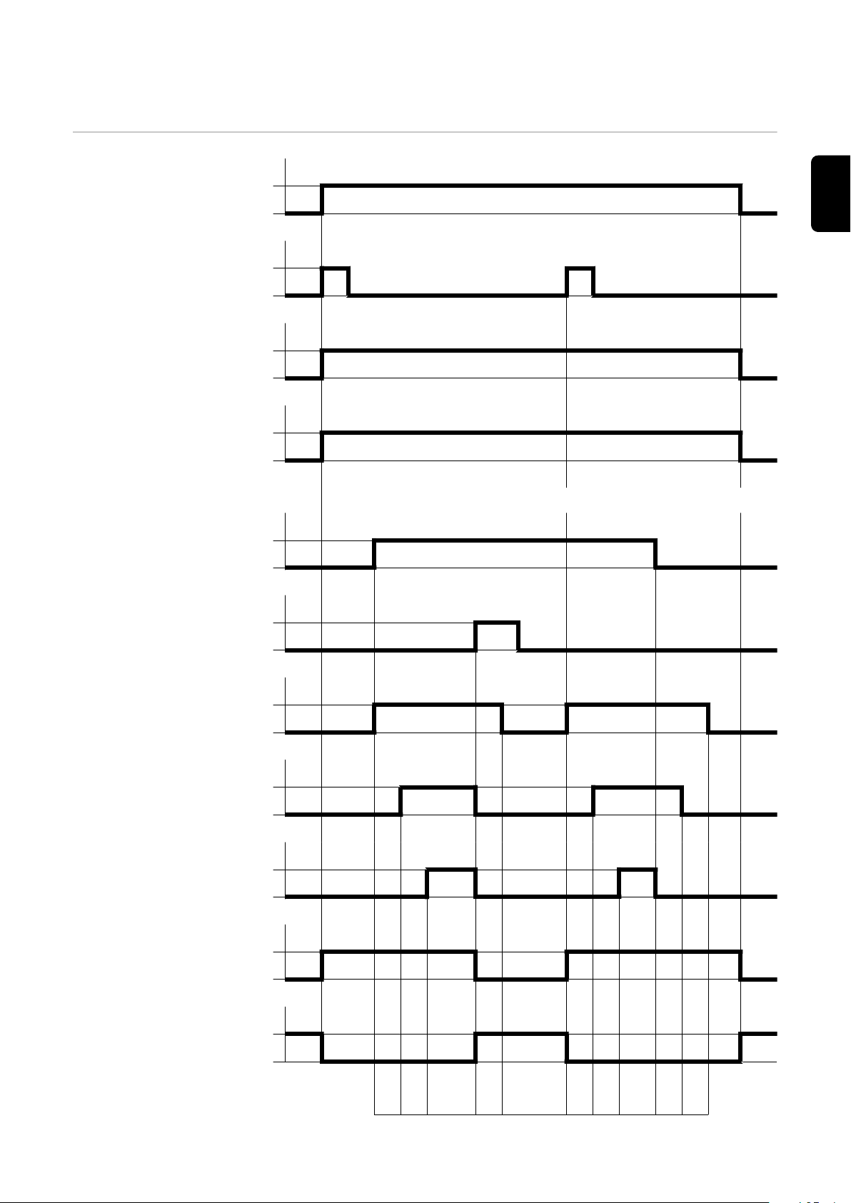
通过 Job 号随限制信号(设备停机)调取时的信号波形
机器人就绪
(Robot ready)
源错误重置
(Source error reset)
模式 Bit 1
(Job mode)
Job 号
(Job / Program bit 0-7)
提示!更多信息请参见章节“Fronius 推荐的步骤”
焊接开始
(Welding start)
工艺激活
ZH
(Process active)
限值错误,关闭
(Stop)
电弧稳定
(Arc stable)
主电流信号
(Main current signal)
电源就绪
(Power source ready)
错误编号
(Error number)
1 2 3 5 1 2 3 4 5
81

(1) 提前送气时间
(2) 起弧电流
(3) 焊接电流
(4) 收弧电流
(5) 滞后停气时间
82

Fronius 推荐的步骤
min. 0,1 s
0
1
0
1
t (s)
t (s)
(1)
(2)
min. 0,3 - 0,8 s
0
1
0
1
t (s)
t (s)
(1)
(2)
同时调取信号
“Job 号”或“程
序编号”和信号
“焊接开始”
在不更改特性数据
的前提下选择 Job/
程序的推荐步骤
注意!
同时调取信号“Job 号”或“程序编号”和信号“焊接开始”会影响到起弧和焊接数据归
档。
在不更改特性数据的前提下选择 Job 或程序时,Fronius 建议在“Job 号”或“程序编
号”信号 (1) 和“焊接开始”信号 (2) 之间至少设定 0.1 s 的时间间隔。
ZH
在不更改特性数据的前提下选择 Job/程序
调取特性曲线或操
作模式会发生变化
在调取特性曲线或操作模式会发生变化的 Job 或程序时,Fronius 建议在“Job 号”或
“程序编号”信号 (1) 和“焊接开始”信号 (2) 之间至少设定 0.3 - 0.8 s 的时间间隔。
的 Job/程序的推荐
步骤
调取特性曲线或操作模式会发生变化的 Job/程序
设定时间间隔 “Job 号”或“程序编号”信号和“焊接开始”信号之间的时间间隔可以借助于提前送气
时间设定:
83

-
在电源上:通过 RCU 5000i 遥控器的设置菜单
-
在机器人控制系统上:Gas preow_time
重要的!
在设置时间间隔时不要使用“Gas purge_time”参数。
84

ZH
85

86

ZH
87

 Loading...