

Page 1

/ Battery Charging Systems / Welding Technology / Solar Electronics
ROB I/O
Bedienungsanleitung
DEENFR
MIG/MAG-Systemerweiterung
Operating Instructions
MIG/MAG system extension
Mode d’emploi
Extension système MIG/MAG
42,0410,1048 002-11042012
Page 2

Page 3

Inhaltsverzeichnis
Kurzbeschreibung ......................................................................................................................................... 2
Allgemeines ............................................................................................................................................. 2
Digitale Eingänge und Ausgänge ............................................................................................................. 2
Prozeßdatenbreite .................................................................................................................................... 2
Eingangssignale vom Roboter zur Stromquelle ....................................................................................... 3
Ausgangssignale vom Roboter zur Stromquelle ...................................................................................... 4
ROB I/O konfigurieren .............................................................................................................................. 5
Gerätespezifische Merkmale ................................................................................................................... 6
Allgemeines................................................................................................................................................... 8
Allgemeine Grundlagen............................................................................................................................ 8
Gerätekonzept.......................................................................................................................................... 8
Montage ROB I/O......................................................................................................................................... 9
Sicherheit ................................................................................................................................................. 9
ROB I/O durch Montage-Bohrungen befestigen ......................................................................................9
ROB I/O an Hutschiene befestigen .......................................................................................................... 9
Technische Daten......................................................................................................................................... 11
Versorgung (über das Local-Net) ............................................................................................................ 11
Digitale Eingänge .................................................................................................................................... 11
Digitale Ausgänge ...................................................................................................................................11
Fronius Worldwide
DE
1
Page 4

Kurzbeschreibung
Allgemeines
Digitale Eingänge
und Ausgänge
Warnung! Fehlbedienung und fehlerhaft durchgeführte Arbeiten können
schwerwiegende Personen- und Sachschäden verursachen. Die in dieser
Anleitung beschriebenen Arbeiten erst dann durchführen, wenn Sie folgende
Dokumente vollständig gelesen und verstanden haben:
- Diese Bedienungsanleitung
- Die Bedienungsanleitung der Stromquelle, insbesondere das Kapitel
„Sicherheitsvorschriften“.
Die Feldbus-Erweiterung ROB I/O dient zur Erweiterung des Signalumfanges für den
Interbus 2 MB. ROB I/O stellt zusätzliche externe Signale am Interbus zur Verfügung.
Zur Verbindung mit der Automatensteuerung, verfügt ROB I/O über einen vorgefertigten
Kabelbaum. Steuerungsseitig ist der Kabelbaum mit einer Lusterklemme vorkonfektioniert.
Hinweis! Zur Vermeidung allfälliger Störungen darf die Leitungslänge, zwischen
ROB I/O und der Steuerung, 1,5 m nicht überschreiten.
Warnung! Gefahr eines Elektroschocks. Mit der Feldbus-Erweiterung ROB I/O
dürfen keine netzbehafteten Komponenten gesteuert werden.
Es sind 4 digitale Eingangssignale und 2 digitale Ausgangssignale verfügbar.
Die digitalen Eingänge und Ausgänge sind galvanisch getrennt
- Gegenseitig
- Gegenüber dem LocalNet und dem Schweißpotential
- Für einen maximalen Spannungsunterschied von 100 V
Prozeßdatenbrei-teROB I/O erhöht die Prozeßdaten-Breite des Interbus 2 MB von 96 Bit auf 112 Bit. Auf-
grund der erweiterten Prozeßdatenbreite, sind am Interbus 2 MB zusätzliche Eingangsund Ausgangssignale verfügbar.
Wichtig! Eine Erweiterung der Prozessdatenbreite findet nur statt:
- Wenn ROB I/O vor dem Einschalten der Versorgungsspannung an die InterbusSteuerung der Stromquelle angeschlossen wurde
- Sobald ROB I/O vom System erkannt wird
Nachfolgende Tabellen zeigen eine Auflistung der
- Standard-Signale für den Interbus 2 MB (in grauer Schrift)
- Zusätzlich von ROB I/O zur Verfügung gestellten Signale (in schwarzer Schrift)
2
Page 5

Eingangssignale
vom Roboter zur
Stromquelle
Eingang Stromquelle Kommentar Bereich Aktivität
E01 Schweißen ein - High
E02 Roboter bereit - High
E03 Betriebsarten Bit 0 - High
E04 Betriebsarten Bit 1 - High
E05 Betriebsarten Bit 2 - High
E06 Unused - -
E07 Unused - -
E08 Unused - -
E09 Gas Test - High
E10 Drahtvorlauf - High
E11 Drahtrücklauf - High
E12 Quellenstörung quittieren - High
E13 Positionssuchen - High
E14 Brennner ausblasen - High
E15 Unused - -
DE
E16 Unused - -
E17 - E24 Job-Nummer - 0 - 99
E25 - E31 Programm-Nummer - 0 - 127
E32 Schweiß-Simulation - High
E33 - E48 Sollwert Leistung 0 - 65535 0 - 100 %
E49 - E64 Sollwert 0 - 65535 -30 - +30 %
Lichtbogenlängenkorrektur
E65 - E72 Sollwert Dynamik / 0 - 255 -5 - +5 %
Puls-Korrektur
E73 - E80 Sollwert Drahtfreibrand 0 - 255 -200 ms -
+200 ms
E81 - E96 Unused - -
E97 Input 1 - -
E98 Input 2 - -
E99 Input 3 - -
E100 Input 4 - -
3
Page 6

Ausgangssignale
vom Roboter zur
Stromquelle
Eingang Stromquelle Kommentar Bereich Aktivität
A01 Stromflußsignal - High
(Lichtbogen aktiv)
A02 Limitsignal (nur RCU 5000i) - -
A03 Prozeß aktiv - High
A04 Hauptstromsignal - High
A05 Kollisionsschutz - High
Schweißbrenner
A06 Stromquelle bereit - High
A07 Kommunikation bereit - High
A08 Reserve - -
A09 Error-Nummer Bit 0 (Wert 1) - High
A10 Error-Nummer Bit 1 (Wert 2) - High
A11 Error-Nummer Bit 2 (Wert 4) - High
A12 Error-Nummer Bit 3 (Wert 8) - High
A13 Error-Nummer Bit 4 (Wert 16) - High
A14 Error-Nummer Bit 5 (Wert 32) - High
A15 Error-Nummer Bit 6 (Wert 64) - High
A16 Error-Nummer Bit 7 (Wert 128) - -
A17 - A24 Unused - Low
A25 Draht-Festbrandkontrolle - High
A26 - A32 Unused - -
A33 - A48 Istwert Schweißspannung 0 - 65535 0 - 100 V
A49 - A64 Istwert Schweißstrom 0 - 65535 0 - 1000 A
A65 - A72 Istwert Motor-Strom 0 - 255 0 - 5 A
Puls-Korrektur
A73 - A80 Unused - -
A81 - A96 Istwert Drahtvorschub 0 - 65535 0 - 22 m
A97 Output 1 - -
A98 Output 2 - -
4
Page 7

ROB I/O konfigurieren
- Software „Servicemodul“ öffnen
- Im Fenster „Servicemodul“ (Knotenliste) den Eintrag „FR Interbus-RL
Fronius ...“ markieren
- Der Button „Konfiguration“ wird
aktiv
- Auf den Button „Konfiguration“ klicken
Es erscheint das Dialogfenster „Configuration Fieldbus“
- Auf den Ordner „System Settings“
klicken
DE
- Im rechten Anzeigefenster „Configuration Fieldbus“ den Eintrag ROB I/O =
„NOT CONNECT“ öffnen
- Es erscheint „Connect“
Das Kontrollfeld neben „Connect“ ankreuzen
- Der Eintrag ROB I/O = „NOT CONNECT“ ändert sich in ROB I/O =
„CONNECT“
- Doppelklick auf den Eintrag ROB I/O
= „CONNECT“
- Doppelklick auf „Filter time“
- Es erscheint der Anzeigewert für
„Filter time“.
Wichtig! Werksseitig ist „Filter time“ auf 30 ms eingestellt. Der Einstellbereich erstreckt
sich von 20 bis 200 ms.
Hinweis! Je höher der Wert desto sicherer, aber auch umso langsamer wird
die Signaländerung.
- Bei Bedarf, den vorgeschlagenen Wert für „Filter time“ ändern
5
Page 8

Gerätespezifische Merkmale
Hinweis! Gilt für Interbus 2 MB Rugged Line, 2 MB Kupfer, FSMA: Die Feld-
bus-Erweiterung ROB I/O wird erst ab Software-Version UBST 1.00.16 (Bussteuerung) unterstützt. Bei älteren Software-Versionen ist ein Update erforderlich.
Der Anschluss von ROB I/O erfolgt über das 10-polige Verbindungskabel an einen 10poligen Anschluss LocalNet der digitalen Stromquelle.
Steht kein freier Anschluss LocalNet zur Verfügung, kann der Verteiler LocalNet passiv
(4,100,261) verwendet werden (z.B. zwischen Stromquelle und Verbindungsschlauchpaket).
Hinweis! Der Verteiler LocalNet passiv ist in Verbindung mit einem Schweißbrenner TIG JobMaster nicht verwendbar.
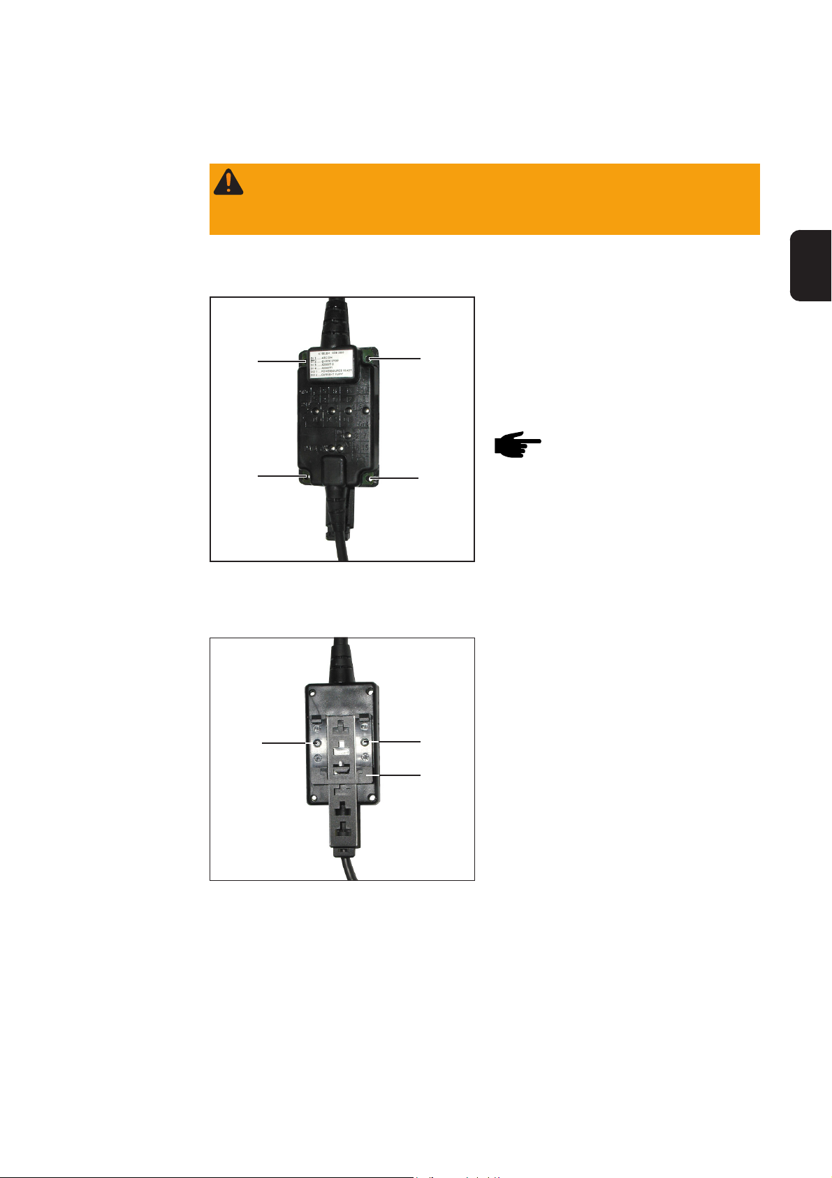
ROB I/O
Lusterklemmen
Stecker
LocalNet
Stromquelle
(2) (3) (4) (5)
(1) (9) (10) (12) (11)
Abb.1 Anzeigen und Anschlüsse an der Feldbus-Systemerweiterung ROB I/O
Klemme1
Klemme2
HI - Input 1
LO - Input 1
HI - Input 2
HI - Input 3
HI - Input 4
LO - Input 4
Output 2
Supply Output 2
GND - Input 1
LO - Input 2
GND - Input 2
LO - Input 3
GND - Input 3
GND - Input 4
Supply Output 1
Output 1
(1) Anzeige DATA OK ... leuchtet, wenn ROB I/O am LocalNet angeschlossen und die
Feldbus-Steuerung versorgt ist
(6) Digitale Eingänge (HI), an Klemme 1, mit externer 24 V - Ansteuerung
Wichtig! Anstelle der Eingänge (6) können auch die potentialfreien Eingänge (7) verwendet werden.
Automatensteuerung
(7) Potentialfreie digitale Eingänge (LO) an Klemme 1
(8) Masse (GND) für die High-aktiven digitalen Eingänge (6), bzw. für die potentialfreien
Eingänge an den Klemmen 1 und 2
(11) Digitale Ausgänge, an den Klemmen 1 und 2
6
Page 9

Gerätespezifische Merkmale:
(Fortsetzung)
(12) Anschlüsse für Versorgung Signalspannung der Digitalen Ausgänge, an den Klem-
men 1 und 2
DE
Automat
V
+ 24 V von der
Automatensteuerung
(Klemme 1/3)
(Klemme 1/11)
Version 1:
externe 24 V
Ansteuerung
GND extern GND input GND input
Klemme 1/3 ........ HI Input 2
Klemme 1/11 ...... GND Input 2
(intern)
V
DC
(Klemme 1/10)
Version 2:
Klemme 1/10 ..... LO Input 2
Klemme 1/11 ..... GND Input 2
(Klemme 1/11)
Potentialfrei
GND inputGND input
(intern)
DC
max. 100 V
max. 100 V
(3)
GND uP
(3)
GND uP
Stromquelle
uP
uP
Abb.2 Eingangssignale Feldbus-Erweiterung ROB I/O
Stromquelle Automat
+ 24 V von der
Automatensteuerung
max. 100 V
(Klemme 2/15)
+ 24 V von der
Automatensteuerung
(9)
uP
Klemme 2/16 ...... Supply Output 1
Klemme 2/15 ...... Output 1
+ 24 V von der
Automatensteuerung
max. 100 V
(9)
Version 2:
„Low-aktiv“
uP
Klemme 2/16 .... Supply Output 1
Klemme 2/15 .... Output 1
Abb.3 Ausgangssignale Feldbus-Erweiterung ROB I/O
(Klemme 2/16)
(Klemme 2/15)
(Klemme 2/16)
/ 20 mA
+ 24 V
DC
+ 24 V von der
Automatensteuerung
/ 20 mA
+ 24 V
DC
7
Page 10

Allgemeines
Allgemeine
Grundlagen
Gerätekonzept ROB I/O ist für den Einbau in einen Schaltschrank geeignet, kann aber praktisch an
beliebiger Position montiert werden.
Vorteile:
- Verbindung zur Feldbus-Steuerung über standardisierte LocalNet-Schnittstelle
- Kein Umbau der Feldbus-Steuerung notwendig
- Einfacher Austausch der Feldbus-Steuerung
- Einfache Steckverbindungen
- Geringer Verdrahtungsaufwand
- Hohe Störsicherheit bei der Datenübertragung
- Montage kann mittels Hutschienenaufnahme erfolgen
Hinweis! Die Feldbus-Erweiterung ROB I/O wird erst ab Software-Version
1.00.16 (Bussteuerung) unterstützt. Bei älteren Software-Versionen ist ein
Update erforderlich.
Hinweis! Der Verteiler LocalNet passiv ist in Verbindung mit einem Schweißbrenner TIG JobMaster nicht verwendbar.
8
Page 11

Montage ROB I/O
DE
Sicherheit
ROB I/O durch
Montage-Bohrungen befestigen
Warnung! Fehlerhaft durchgeführte Arbeiten können schwerwiegende Personen-
und Sachschäden verursachen. Nachfolgend beschriebene Tätigkeiten dürfen nur
von geschultem Fachpersonal durchgeführt werden! Beachten Sie die Sicherheitsvorschriften.
Wichtig! Bei Montage des ROB I/O durch
die Montage-Bohrungen (1) Folgendes
beachten:
(1)
(1)
Abb.4 Montage-Bohrungen Ø 4,2 mm (0,17 in.)
(1)
(1)
- Nur geeignete Schrauben verwenden
(Bohrungsdurchmesser Ø 4,2 mm
(0,17 in.)
- Immer mit 4 Schrauben gleichmäßig
befestigen
Hinweis! Schrauben nicht zu fest
anziehen. Zu hohes Anziehdrehmoment kann das ROB I/O
beschädigen oder sogar zum
Bruch führen.
max. Anziehdrehmoment 0,4 Nm
ROB I/O an
Hutschiene
befestigen
(3)
Abb.5 Hutschienenaufnahme an ROB I/O montie-
ren
(3)
(2)
1. Beiliegende Hutschienenaufnahme
(2) mit 2 Schrauben (3) am Roboterinterface ROB I/O befestigen.
9
Page 12

ROB I/O an
Hutschiene
befestigen
(Fortsetzung)
2. Fixiernasen (4) der Hutschienenaufnahme an der Hutschiene (5) einhaken
(4)(4)
(5)
(4)
Abb.6 ROB I/O an Hutschiene befestigen
3. ROB I/O an der Unterseite gegen die
Hutschiene (5) drücken
4. Arretierung rastet ein
andrücken
Abb.7 Vorderansicht ROB I/O an Hutschiene
10
Page 13

Technische Daten
DE
Versorgung (über
das Local-Net)
Digitale Eingänge
Bedingung minimal typisch maximal
Versorgungsspannung Dauerbetrieb 15 V
DC
24 V
DC
30 V
Stromaufnahme Versorgungsspannung = 24 V 50 mA 100 mA 300 mA
Stromaufnahme Standby Versorgungsspannung = 24 V 50 mA 60 mA 80 mA
Bedingung Potentialfrei (LO) High-aktiv (HI)
U
0
U
On
U
Off
U
Hyst
I
On
C
Input
U
Inv
U
Max
Eingang unbenutzt, keine Stromaufnahme 18 V
Einschaltschwelle 1,2 V
Ausschaltschwelle 1,25 V
DC
DC
DC
Hysterese 50 mV 100 mV
Eingangsstrom beim Einschaltvorgang - 10 mA 330 uA
Eingangskapazität 47 nF 47 nF
falsch gepolte Eingangsspannung 60 VDC (Max.) 60 VDC (Max.)
Überspannungsschutz Eingang 100 VDC / 42 VAC (Max.) 100 VDC / 42 VAC (Max.)
0 V
6,6 V
6,5 V
DC
DC
DC
DC
Digitale Ausgänge
Bedingung minimal typisch maximal
U
0
I
Shift
I
SC
U
Max
U
Invers
R
Open
R
On
U
On
C
Output
falsch gepolte Ausgangsspannung 60 V
Eingangswiderstand bei offenem Ausgang 100 kOhm
Eingangswiderstand bei aktivem Ausgang 8 Ohm 10 Ohm 12 Ohm
Zu schaltende Spannung 24 V
Schaltstrom 0 A - 20 mA
Kurzschlußstrom (dauerhaft) 30 mA
Überspannungsschutz 60 VDC / 42 V
Eingangsrestspannung 1 V
Ausgangskapazität 47 nF
dU / dT Spannungsänderung bei einem Schaltvorgang 0,5 VDC / us
Hinweis! Die angeführten technischen Daten entsprechen dem Stand bei
Drucklegung. Änderungen vorbehalten.
DC
42 V
DC
AC
DC
DC
11
Page 14

12
Page 15

Contents
Brief description ............................................................................................................................................ 2
General remarks ...................................................................................................................................... 2
Digital inputs and outputs ......................................................................................................................... 2
Process data width ................................................................................................................................... 2
Input signals from the robot to the power source ..................................................................................... 3
Output signals from the robot to the power source .................................................................................. 4
How to configure ROB I/O........................................................................................................................ 5
Machine-specific features ........................................................................................................................ 6
General remarks ........................................................................................................................................... 8
General requirements .............................................................................................................................. 8
Machine concept ...................................................................................................................................... 8
Mounting ROB I/O ........................................................................................................................................ 9
Safety ....................................................................................................................................................... 9
Fasten ROB I/O via mounting bores ........................................................................................................ 9
Fastening the ROB I/O to the top-hat rail ................................................................................................. 9
Technical data ..............................................................................................................................................11
Power supply (via the Local-Net) ............................................................................................................11
Digital inputs............................................................................................................................................ 11
Digital outputs ......................................................................................................................................... 11
Fronius Worldwide
EN
1
Page 16

Brief description
General remarks
Digital inputs and
outputs
Warning! Operating the equipment incorrectly and work that is not carried out
correctly can cause serious injury and damage. Do not use the functions
described here until you have read and completely understood all of the following documents:
- this “Operating Instructions“ manual
- the instruction manual of the power source being used, especially the
“Safety rules“.
The ROB I/O fieldbus extend module enables the 2 MB Interbus to send and receive
additional external signals.
The ROB I/O has a pre-assembled cable harness for linking it to the automatic-welder
control system. At the control-system end of the cable harness, it is pre-fabricated with a
lamp-wire connector.
Note! To avoid malfunctions, the length of the cable between the ROB I/O and
the control system must not be more than 1.5 m.
Warning! Electric shock hazard. Do not use the ROB I/O extend module to
control mains-powered components.
Process data
width
4 digital input signals and 2 digital output signals are available on the bus.
The digital inputs and outputs are galvanically separated:
- from one another
- from the LocalNet and the welding potential
- for a maximum voltage difference of 100 V
The ROB I/O module enables the 2 MB Interbus to transfer 112 bit wide instead of 96 bit
wide process data. As a result, additional input and output signals are available on the 2
MB Interbus.
Important! The 112 bit wide process data width is only available:
- if the ROB I/O module has been connected to the power source Interbus control
prior to energising the Interbus control
- as soon as the system recognises the ROB I/O module
In following tables the signals are listed as follows:
- standard signals for the 2 MB Interbus (in grey characters)
- additional signals available when using the ROB I/O module (in black characters)
2
Page 17

Input signals
from the robot to
the power source
Power source input Commentary Range Activity
E01 Welding on - High
E02 Robot ready - High
E03 Operating modes Bit 0 - High
E04 Operating modes Bit 1 - High
E05 Operating modes Bit 2 - High
E06 Unused - -
E07 Unused - -
E08 Unused - -
E09 Gaz test - High
E10 Wire feeding - High
E11 Wire reversing - High
E12 Acknowledge source failure - High
E13 Touch sensing - High
E14 Torch purging - High
E15 Unused - -
E16 Unused - -
E17 - E24 Job number - 0 - 99
E25 - E31 Program number - 0 - 127
E32 Welding simultation - High
EN
E33 - E48 Setpoint: welding performance 0 - 65535 0 - 100 %
E49 - E64 Setpoint: arc voltage control 0 - 65535 -30 - +30 %
E65 - E72 Setpoint: arc force/pulse 0 - 255 -5 - +5 %
correction
E73 - E80 Setpoint: burn-back 0 - 255 -200 ms -
+200 ms
E81 - E96 Unused - -
E97 Input 1 - -
E98 Input 2 - -
E99 Input 3 - -
E100 Input 4 - -
3
Page 18

Output signals
from the robot to
the power source
Power source input Commentary Range Activity
A01 Current-flow signal - High
(with active welding arc)
A02 Limit signal (nur RCU 5000i) - -
A03 Process active - High
A04 Main current signal - High
A05 Welding torch anti-collision - High
sensing
A06 Power source ready - High
A07 Communication ready - High
A08 Reserve - -
A09 Error number bit 0 (value 1) - High
A10 Error number bit 1 (value 2) - High
A11 Error number bit 2 (value 4) - High
A12 Error number bit 3 (value 8) - High
A13 Error number bit 4 (value 16) - High
A14 Error number bit 5 (value 32) - High
A15 Error number bit 6 (value 64) - High
A16 Error number bit 7 (value 128) - -
A17 - A24 Unused - Low
A25 Wire stick control - High
A26 - A32 Unused - -
A33 - A48 Actual value: welding voltage 0 - 65535 0 - 100 V
A49 - A64 Actual value: welding current 0 - 65535 0 - 1000 A
A65 - A72 Actual value: motor current 0 - 255 0 - 5 A
Pulse correction
A73 - A80 Unused - -
A81 - A96 Actual value: wire feeder 0 - 65535 0 - 22 m
A97 Output 1 - -
A98 Output 2 - -
4
Page 19

How to configure
ROB I/O
- Open Service Module software
- On the Service Module screen (node
list), mark the item „FR Interbus-RL
Fronius ...“
- The Configuration button is activa-
ted
- Click the Configuration button
EN
The Configuration Fieldbus dialog box opens.
- Click the System Settings folder.
- In the right-hand Configuration Fieldbus display window, open entry ROB
I/O = „NOT CONNECT“
- “Connect“ appears.
Check the checkbox beside „Connect“
- The entry ROB I/O = „NOT CONNECT“ changes to ROB I/O = „CONNECT“
- Double-click the entry ROB I/O =
„CONNECT“
- Double-click „Filter time“
- The value set for„Filter time“ is displayed.
Important! The value for „Filter time“ is set to 30 ms at the factory. „Filter time“ can be
set to a value ranging from 20 to 200 ms.
Note! The higher the setting, the more safely yet slowly the signal changes.
- If necessary, change the value set for „Filter time“.
5
Page 20

Machine-specific
features
Note! Applicable to Interbuses 2 MB Rugged Line, 2 MB Copper, FSMA: The
ROB I/O fieldbus extend module is supported only by a bus control with a
software version UBST 1.00.16 or higher. Older software versions will need to
be updated.
The ROB I/O is connected via a 10-pole interconnecting cable to a 10-pole LocalNet
connection on the digital power source.
If there is no free LocalNet connection available, the LocalNet passive distributor
(4,100,261) can be used (e.g. between the power source and the interconnecting hosepack).
Note! The LocalNet passive distributor cannot be used together with a TIG
JobMster welding torch.
ROB I/O
Lamp wire
Power source
connectors
Plug LocalNet
(2) (3) (4) (5)
(1) (9) (10) (12) (11)
Terminal1
Terminal2
HI - Input 1
LO - Input 1
HI - Input 2
HI - Input 3
HI - Input 4
LO - Input 4
Output 2
Supply Output 2
GND - Input 1
LO - Input 2
GND - Input 2
LO - Input 3
GND - Input 3
GND - Input 4
Supply Output 1
Output 1
Automatic-welder control system
Fig.1 Indicators and connections of the ROB I/O fieldbus system extend
(1) DATA OK indicator ... lights up when the ROB I/O is connected to the LocalNet and
the field-bus control is switched on
(6) Digital inputs (HI), on Terminal 1, with external 24 V activation
Important! Instead of the inputs (6), it is also possible to use the potential-free inputs (7).
(7) Potential-free digital inputs (LO), on Terminal 1
(8) Earth (GND) for the high-active digital inputs (6), or for the potential-free inputs, on
Terminals 1 and 2
(11) Digital outputs, on Terminals 1 and 2
6
Page 21

Machine-specific
features
(continued)
(12) Connections for signal voltage supply of the digital outputs, on Terminals 1 and 2
Automatic welder
V
+ 24 V from the automaticwelder control system
(Terminal 1/3)
(Terminal 1/11)
Version 1:
external 24 V
activation
GND external GND input GND input
Terminal 1/3 ....... HI Input 2
Terminal 1/11 ..... GND Input 2
(internal)
V
DC
(internal)
DC
max. 100 V
max. 100 V
(3)
GND uP
(3)
Power source
uP
EN
(Terminal 1/10)
Version 2:
Terminal 1/10 .... LO Input 2
Terminal 1/11 .... GND Input 2
(Terminal 1/11)
Potential-free
GND uP
GND inputGND input
uP
Fig.2 Input signals of the ROB I/O fieldbus system extend
Power source Automatic-welder
+ 24 V from the automaticwelder control system
max. 100 V
(Terminal 2/15)
+ 24 V from the
automatic-welder
control system
(9)
uP
Version 1:
„High-activ“
Terminal 2/16 .....Supply Output 1
Terminal 2/15 .....Output 1
+ 24 V from the automaticwelder control system
max. 100 V
(9)
Version 2:
„Low-activ“
uP
Terminal 2/16 ... Supply Output 1
Terminal 2/15 ... Output 1
Fig.3 Output signals of the ROB I/O fieldbus system extend
(Terminal 2/16)
(Terminal 2/15)
(Terminal 2/16)
+ 24 V
/ 20 mA
DC
+ 24 V from the
automatic-welder
control system
/ 20 mA
+ 24 V
DC
7
Page 22

General remarks
General requirements
Machine concept The ROB I/O is designed to be installed in a control cubicle, although it can also be
mounted in practically any desired position.
Advantages:
- Linked up to field-bus control via standardised LocalNet interface
- No need for any modifications to the field-bus control
- Field-bus control can easily be changed
- Simple plug-in connections
- Limited amount of wiring and cabling needed
- High degree of interference immunity during data transmission
- Can be mounted using top-hat rail holder
Note! The ROB I/O fieldbus extend module is supported only by a bus control
with a software version 1.00.16 or higher. Older software versions will need to
be updated.
Note! The LocalNet passive distributor cannot be used together with a TIG
JobMaster welding torch.
8
Page 23

Mounting ROB I/O
Safety
Fasten ROB I/O
via mounting
bores
Warning! Work that is not carried out correctly can cause serious injury and
damage. The actions described below may ONLY be carried out by skilled,
Fronius-trained technicians! Read and follow the section headed “Safety rules”.
Important! When mounting ROB I/O via
the mounting bores (1) the following shall
be observed:
(1)
(1)
Fig.4 Mounting bores Ø 4.2 mm (0.17 in.)
(1)
(1)
- Use only appropriate screws (diameter of bore Ø 4.2 mm (0.17 in.)
- Fix always regularly by means of 4
screws
Note! Don’t tighten the screws
too much. An excessive tightening torque may damage the
ROB I/O and even lead to breakage.
Max. tightening torque 0.4 Nm
EN
Fastening the
ROB I/O to the
top-hat rail
(3)
Fig.5 Mount the top-hat rail holder to the ROB I/O
(3)
(2)
1. Fasten the enclosed top-hat rail
holder (2) onto the robot interface
ROB I/O, using 2 screws (3).
9
Page 24

Fastening the
ROB I/O to the
top-hat rail
(continued)
2. Hook the positioning lugs (4) of the tophat rail holder to the top-hat rail (5)
(4)(4)
(5)
(4)
Fig.6 Fasten ROB I/O to top-hat rail
3. Press the bottom of the ROB I/O up
against the top-hat rail (5)
4. The retainer snaps into place
Press up
Fig.7 Front view of ROB I/O to top-hat rail
10
Page 25

Technical data
Power supply
(via the LocalNet)
Digital inputs
Condition minimum typical maximum
Supply voltage Continous operation 15 V
DC
24 V
DC
30 V
Power consumption Supply voltage = 24 V 50 mA 100 mA 300 mA
Standby power consumtion Supply voltage = 24 V 50 mA 60 mA 80 mA
Condition Potential-free (LO) High-active (HI)
U
0
U
On
U
Off
U
Hyst
I
On
C
Input
U
Inv
U
Max
Input unused, no power consumption 18 V
Switch-ON thresold 1,2 V
Switch-OFF thresold 1,25 V
DC
DC
DC
Hysteresis 50 mV 100 mV
Input current in “make” operation - 10 mA 330 uA
Input capacity 47 nF 47 nF
Inversely poled input voltage 60 VDC (Max.) 60 VDC (Max.)
Input overvoltage protection 100 VDC / 42 VAC (Max.) 100 VDC / 42 VAC (Max.)
0 V
6,6 V
6,5 V
DC
DC
DC
DC
EN
Digital outputs
Condition minimum typical maximum
U
0
I
Shift
I
SC
U
Max
U
Invers
R
Open
R
On
U
On
C
Output
Short-circuit current (continuous) 30 mA
Input resistance where output is open 100 kOhm
Input resistance where output is active 8 Ohm 10 Ohm 12 Ohm
Voltage to be switched 24 V
Switched current 0 A - 20 mA
Overvoltage protection 60 VDC / 42 V
Inversely poled output voltage 60 V
Input residual voltage 1 V
Output capacity 47 nF
dU / dT Change in voltage from a switching operation 0,5 VDC / us
Note! The technical data given above were technically correct at the time of
going to print. We reserve the right to effect alterations.
DC
42 V
DC
AC
DC
DC
11
Page 26

12
Page 27

Sommaire
Description succincte .................................................................................................................................... 2
Généralités ............................................................................................................................................... 2
Digitale Eingänge und Ausgänge ............................................................................................................. 2
Largeur des données du processus ......................................................................................................... 2
Signaux d‘entrée du robot à la source de courant.................................................................................... 3
Signaux de sortie du robot à la source de courant ................................................................................... 4
Configurer ROB I/O .................................................................................................................................. 5
Caractéristiques spécifiques à l‘appareil .................................................................................................. 6
Généralités .................................................................................................................................................... 8
Principes de base..................................................................................................................................... 8
Conception de l‘appareil ........................................................................................................................... 8
Montage de ROB I/O..................................................................................................................................... 9
Sécurité .................................................................................................................................................... 9
Fixer ROB I/O à l´aide des trous de montage .......................................................................................... 9
Fixer le ROB I/O sur le profilé chapeau ................................................................................................... 9
Caractéristiques techniques .........................................................................................................................11
Alimentation (par le Local-Net) ................................................................................................................ 11
Entrées numériques ................................................................................................................................11
Sorties numériques .................................................................................................................................11
Fronius Worldwide
FR
1
Page 28

Description succincte
Généralités
Digitale Eingänge
und Ausgänge
Avertissement ! Toute erreur de manipulation ou tout travail incorrectement
réalisé peut occasionner des dommages matériels ou personnels lourds de
conséquences. N’effectuez les travaux décrits dans ce manuel qu’après avoir
entièrement lu et compris la documentation suivante :
- Ce manuel opératoire
- Le manuel opératoire du générateur de soudage, plus particulièrement le
chapitre “consignes de sécurité“.
Le module d‘extension bus ROB I/O sert à augmenter le nombre des signaux pouvant
être émis et reçus par l‘Interbus 2 MB.
Le ROB I/O dispose d’un faisceau préparé pour la connexion à la commande de
l’automate. Du côté de la commande, le faisceau est doté d’un domino préconfectionné.
Note ! Pour éviter les interférences, le faisceau reliant le ROB I/O à la commande ne devrait pas dépasser 1,5 m de longueur
Avertissement! Danger d‘électrocution. Le module d‘extension bus ROB I/O
ne peut pas être utilisé pour commander des composants alimentés du réseau.
Largeur des
données du
processus
4 signaux d‘entrée numériques et 2 signaux de sortie numériques sont disponibles.
Les entrées et sorties numériques sont isolées galvaniquement
- mutuellement
- par rapport au LocalNet et au potentiel de soudage
- pour un écart de tension de max. 100 V
ROB I/O permet d‘étendre de 96 bit à 112 bit la largeur des données du processus de
l‘Interbus 2 MB. Donc un nombre additionnel de signaux d‘entrée et de sortie est disponible à l‘interbus 2 MB.
Important! La largeur des données du processus n‘est élargie que:
- si le module ROB I/O est raccordé à la commande Interbus de la source de courant
avant sa mise sous tension
- après le système ait reconnu le module ROB I/O
Les tableaux suivants listent
- les signaux standards pour l‘Interbus 2 MB (en caractères gris)
- les signaux additionnels disponibles moyennant l‘emploi du ROB I/O (en caractères
noirs)
2
Page 29

Signaux d‘entrée
du robot à la
source de courant
Entrée source de courant Commentaire Gamme Activité
E01 Soudure Marche - Haut
E02 Robot prêt - Haut
E03 Modes de service Bit 0 - Haut
E04 Modes de service Bit 1 - Haut
E05 Modes de service Bit 2 - Haut
E06 Sans usage - -
E07 Sans usage - -
E08 Sans usage - -
E09 Test de gaz - Haut
E10 Avance de fil - Haut
E11 Retour de fil - Haut
E12 Confirmer malfonctionnement
de la source - Haut
E13 Touch sensing - Haut
E14 Purger torche - Haut
E15 Sans usage - -
FR
E16 Sans usage - -
E17 - E24 Numéro du job - 0 - 99
E25 - E31 Numéro du programme - 0 - 127
E32 Similuation du soudage - Haut
E33 - E48 Puissance de consigne 0 - 65535 0 - 100 %
E49 - E64 Valeur de consigne:
correction de la longueur de l‘arc 0 - 65535 -30 - +30 %
E65 - E72 Valeur de consigne: dynamique / 0 - 255 -5 - +5 %
correction d‘impulsions
E73 - E80 Valeur de consigne: burn-back 0 - 255 -200 ms -
+200 ms
E81 - E96 Sans usage - -
E97 Entrée 1 - -
E98 Entrée 2 - -
E99 Entrée 3 - -
E100 Entrée 4 - -
3
Page 30

Signaux de sortie
du robot à la
source de courant
Entrée source de courant Commentaire Gamme Activité
A01 Signal conduction de courant - Haut
(arc de soudage actif)
A02 Signal limite (seulement RCU 5000i) - -
A03 Processus actif - Haut
A04 Signal courant principal - Haut
A05 Anti-collision - Haut
Torche de soudage
A06 Source de courant prête - Haut
A07 Communication prête - Haut
A08 Réserve - -
A09 Numéro erreur Bit 0 (valeur 1) - Haut
A10 Numéro erreur Bit 1 (valeur 2) - Haut
A11 Numéro erreur Bit 2 (valeur 4) - Haut
A12 Numéro erreur Bit 3 (valeur 8) - Haut
A13 Numéro erreur Bit 4 (valeur 16) - Haut
A14 Numéro erreur Bit 5 (valeur 32) - Haut
A15 Numéro erreur Bit 6 (valeur 64) - Haut
A16 Numéro erreur Bit 7 (valeur 128) - -
A17 - A24 Sans usage - Bas
A25 Contrôle immobilisation fil (wire-stick)- Haut
A26 - A32 Sans usage - -
A33 - A48 Soudage de tension éffective 0 - 65535 0 - 100 V
A49 - A64 Courant de soudage éffectif 0 - 65535 0 - 1000 A
A65 - A72 Courant moteur éffectif 0 - 255 0 - 5 A
Correction d‘impulsions
A73 - A80 Sans usage - -
A81 - A96 Avance de fil éffective 0 - 65535 0 - 22 m
A97 Sortie 1 - -
A98 Sortie 2 - -
4
Page 31

Configurer
ROB I/O
- Ouvrir logiciel «Service module»
- Dans la fenêtre «Service module»
(liste de noeuds), marquer l’élément
«FR Interbus-RL Fronius ...»
- Le bouton «Configuration»
s’active.
- Cliquer sur le bouton «Configuration»
La fenêtre de dialogue «Configuration Fieldbus» s’affiche
- Cliquer sur le classeur «System
Settings»
- Dans la fenêtre d’affichage droite
«Configuration Fieldbus», ouvrir
l’élément ROB I/O = „NOT
CONNECT“
- L’élément «Connect» s’affiche.
FR
Cocher la case à côté de «Connect»
- L’élément ROB I/O = „NOT CONNECT“ se transforme en ROB I/O =
„CONNECT“
- Cliquer deux fois sur l’élément ROB I/
O = „CONNECT“
- Cliquer deux fois sur «Filter time»
- La valeur réglée pour «Filter time»
s’affiche.
Important! «Filter time» est réglée sur 30 ms en usine et peut être réglé sur une valeur
comprise entre 20 et 200 ms.
Note! Plus élevée la valeur, plus sure mais néanmoins plus lente la transformation du signal.
- Si nécessaire, changer la valeur proposée pour «Filter time».
5
Page 32

Caractéristiques
spécifiques à
l‘appareil
Note! Valable pour les Interbus 2 MB Rugged Line, 2 MB Cuivre, FSMA: Le
module d’extension bus de terrain ROB I/O ne fonctionne qu’avec un logiciel
(commande bus) de version UBST 1.00.16 et plus. Une mise à jour des
versions de logiciel plus anciennes est nécessaire,
Le ROB I/O se branche sur un connecteur LocalNet à 10 pôles du générateur de soudage numérique à l’aide d’un câble de liaison à 10 pôles.
Lorsqu’il n’y a pas de connecteur LocalNet disponible, il est possible d’utiliser le distributeur LocalNet passif (4,100,261) (p. ex. entre le générateur de soudage et le faisceau de
liaison).
Note ! Le distributeur LocalNet passif n’est pas utilisable en combinaison avec
une torche TIG JobMaster.
ROB I/O
Dominos
Prise LocalNet
Générateur
(2) (3) (4) (5)
(1) (9) (10) (12) (11)
Fig.1 Indications et connexions sur le module d‘extension de systeme bus de terrain ROB I/O
Borne 1
Borne 2
HI - entrée 1
LO - entrée 1
HI - entrée 2
HI - entrée 3
HI - entrée 4
LO - entrée 4
Sortie 2
Alimentation sortie 2
Terre entrée 1
LO - entrée 2
Terre - entrée 2
LO - entrée 3
Terre - entrée 3
Terre - entrée 4
Alimentation sortie 1
Sortie 1
(1) Voyant DATA OK ... s’allume lorsque le ROB I/O est connecté au LocalNet et que la
commande de bus de terrain est en circuit
(6) Entrées numériques (HI), à la borne 1, avec commande externe 24 V
Important ! Il est également possible d’utiliser les entrées sans potentiel (7) au lieu des
entrées (6).
Commande de l‘automate
(7) Entrées numériques sans potentiel (LO) à la borne 1
(8) Prise de terre pour les entrées numériques activées au niveau HAUT (6) / pour les
entrées sans potentiel aux bornes 1 et 2
(11) Sorties numériques aux bornes 1 et 2
6
Page 33

Caractéristiques
spécifiques à
l‘appareil
(suite)
(12) Connexions pour l’alimentation en tension du signal des sorties numériques aux
bornes 1 et 2
Automate
V
DC
+ 24 V de la commande de
l‘automate
(Borne 1/3)
(Borne 1/11)
Version 1:
commande
24 V externe
Terre externe Terre entrée Terre entrée
Borne 1/3 ............HI entrée 2
Borne 1/11 ..........Terre entrée 2
(interne)
V
DC
max. 100 V
(interne)
max. 100 V
(3)
Terre uP
(3)
Générateur
de soudage
uP
FR
(Borne 1/10)
Version 2:
sans potenteil
Borne 1/10 ......... LO entrée 2
Borne 1/11 ......... Terre entrée 2
(Borne 1/11)
Terre entréeTerre entrée
Fig.2 Signaux d‘entrée module d‘extension bus de terrain ROB I/O
Générateur de
soudage
+ 24 V de la commande de
l‘automate
max. 100 V
(Borne 2/15)
(9)
uP
Version 1:
“état haut -
activé“
Borne 2/16 ..........Alimentation sortie 1
Borne 2/15 ..........Sortie 1
+ 24 V de la commande de
l‘automate
max. 100 V
Version 2:
Borne 2/16 ........ Alimentationsortie 1
Borne 2/15 ........ Sortie 1
(9)
“état bas -
activé“
uP
Fig.3 Signaux de sortie module d‘extension bus de terrain ROB I/O
(Borne 2/16)
(Borne 2/15)
(Borne 2/16)
uP
Terre uP
+ 24 V de la commande
de l‘automate
+ 24 V
/ 20 mA
DC
+ 24 V de la commande
de l‘automate
/ 20 mA
+ 24 V
DC
Automate
7
Page 34

Généralités
Principes de
base
Conception de
l‘appareil
Note! Le module d’extension bus de terrain ROB I/O ne fonctionne qu’avec un
logiciel (commande bus) de version 1.00.16 et plus. Une mise à jour des
versions de logiciel plus anciennes est nécessaire.
Le ROB I/O est conçu pour l’installation dans une armoire de commande, mais peut se
monter à n’importe quelle position.
Avantages
- Connexion à la commande de bus de terrain par interface LocalNet standard
- Pas de transformation de la commande de bus de terrain nécessaire
- Changement aisé de la commande de bus de terrain
- Connecteurs simples
- Travaux de câblage restreints
- Grande insensibilité aux parasites lors de la transmission de données
- Possibilité de montage à l’aide de profilés chapeaux
Note ! Le distributeur LocalNet passif n’est pas utilisable en combinaison avec
une torche TIG JobMaster.
8
Page 35
Montage de ROB I/O
Sécurité
Fixer ROB I/O à
l´aide des trous
de montage
Avertissement! Les travaux mal faits peuvent causer des dommages corporels
et matériels graves. Les opérations décrites ci-après ne doivent être effectuées
que par un membre du personnel formé. Observez les indications du chapitre
‘’Consignes de sécurité’’.
Important! Lors du montage de ROB I/O
à l´aide des trous de montage (1) respectez les consignes suivantes:
(1)
(1)
Fig.4 trous de montage Ø 4,2 mm (0,17 in.)
(1)
(1)
- n´utiliser que des vis appropriées
(diamètre du trou Ø 4,2 mm (0,17 in.))
- toujours serrer régulièrement à l´aide
de 4 vis
Note! Ne pas trop serrer les vis.
Un couple de serrage trop élevé
peut endommager ROB I/O ou
même le briser.
Couple de serrage max. 0,4 Nm
FR
Fixer le ROB I/O
sur le profilé
chapeau
(3)
Fig.5 Monter le support de profilé chapeau sur le
ROB I/O
(3)
(2)
1. Fixer les supports de profilés chapeaux (2) avec les vis (3) - fournis en
équipement standard -sur l’interface
robot ROB I/O.
9
Page 36

Fixer le ROB I/O
sur le profilé
chapeau
(suite)
2. Accrocher les tenons de fixation (4)
du support sur le profilé chapeau (5)
(4)(4)
(5)
(4)
Fig.6 Fixer le ROB I/O sur le profilé chapeau
3. Presser la face inférieure du ROB I/O
contre le profilé chapeau (5)
4. Le dispositif de fixation s’encliquette
presser
Fig.7 Vue avant du ROB I/O sur le profilé
chapeau
10
Page 37

Caractéristiques techniques
Alimentation (par
le Local-Net)
Entrées numériques
Condition min. typ. max.
Tension d‘alimentation Régime permanent 15 V
DC
24 V
DC
30 V
Consommation Tension d‘alimentation = 24 V 50 mA 100 mA 300 mA
Consommation en veille Tension d‘alimentation = 24 V 50 mA 60 mA 80 mA
Condition Sans potentiel (LO) Activé HAUT (HI)
U
Entrée non utilisée, pas de consommation él. 18 V
0
U
On
U
Off
U
Hyst
I
On
C
Input
U
Inv
U
Max
Courant d‘entrée au démarrage - 10 mA 330 uA
Tension d‘entrée mal polarisée 60 VDC (max.) 60 VDC (max.)
Prot. contre les surtensions à l‘entrée 100 VDC / 42 VAC (max.) 100 VDC / 42 VAC (max.)
Seuil de commutation 1,2 V
Seuil d‘arrêt 1,25 V
Hystérésis 50 mV 100 mV
Capacité d‘entrée 47 nF 47 nF
DC
DC
DC
0 V
6,6 V
6,5 V
DC
FR
DC
DC
DC
Sorties numériques
Condition min. typ. max.
U
0
I
Shift
I
SC
U
Max
U
Invers
R
Open
R
On
U
On
C
Output
Courant de court-circuit 8permanent) 30 mA
Protection contre les surtensions 60 VDC / 42 V
Tension de sortie mal polarisée 60 V
Impédance d‘entrée avec sortie ouverte 100 kOhm
Impédance d‘entrée avec sortie activée 8 Ohm 10 Ohm 12 Ohm
Tension à appliquer 24 V
Courant de marche/arrêt 0 A - 20 mA
Tension d‘entrée résiduelle 1 V
Capacité de sortie 47 nF
dU / dT Fluctuation de tension lors d‘une commutation 0,5 VDC / us
Note ! Les caractéristiques techniques indiquées répondent à l’état de la
technique au moment de l’impression. Sous réserve de modifications.
DC
42 V
DC
AC
DC
DC
11
Page 38

FRONIUS INTERNATIONAL GMBH
Froniusplatz 1, A-4600 Wels, Austria
Tel: +43 (0)7242 241-0, Fax: +43 (0)7242 241-3940
E-Mail: sales@fronius.com
www.fronius.com
Under http://www.fronius.com/addresses you will find all addresses
www.fronius.com/addresses
of our Sales & service partners and Locations.
ud_fr_st_so_00082 012011
 Loading...