

Page 1
Fronius prints on elemental chlorine free paper (ECF) sourced from certified sustainable forests (FSC).
/ Perfect Charging / Perfect Welding / Solar Energy
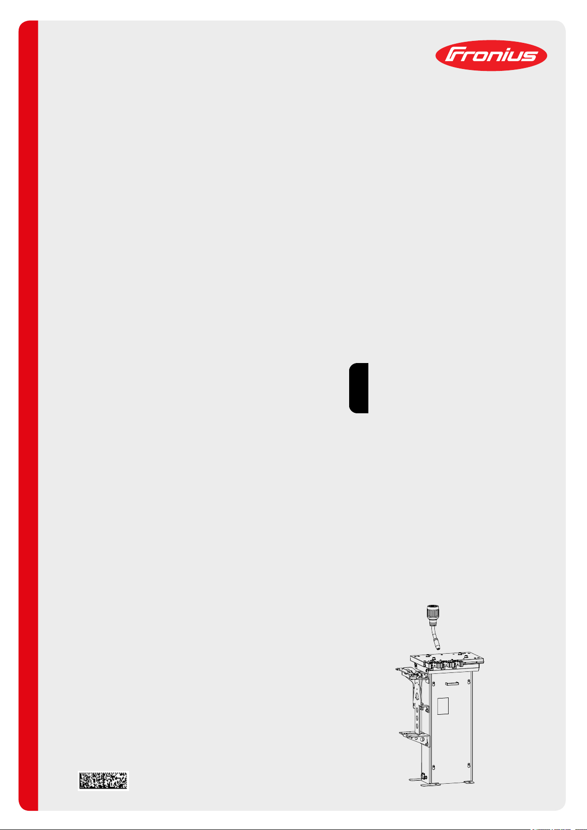
Robacta TX 10i/G/W console
Operating instructions
EN
42,0426,0170,EN 008-27102021
Page 2

Page 3

Contents
Safety rules 6
Explanation of safety notices 6
General 6
Proper use 7
Environmental conditions 7
Obligations of the operator 7
Obligations of personnel 7
Specific hazards 7
Protecting yourself and others 8
EMC Device Classifications 8
EMC measures 8
EMF measures 9
Safety measures at the installation location and during transport 9
Safety measures in normal operation 9
Commissioning, maintenance and repair 10
Safety inspection 10
Disposal 10
Safety symbols 10
Data protection 10
Copyright 10
General information 13
EN
General 15
Device concept 15
Necessary system components 15
Compatible system components for the overall welding system 17
Scope of supply 17
Proper use 17
Note on wire feeding 18
Warning notices on the device 19
Warning notices on the device 19
Transport 20
Transport devices 20
Transport notices on the packaging 20
Controls, connections and mechanical components 21
Controls, connections and mechanical components 23
Safety 23
Controls and connections 23
Mechanical components 24
Pin assignments and signal descriptions 25
Safety 25
Assignment of standard I/O connection for robot control 25
Signal descriptions 27
Assignment of connection to external options 29
Installation and commissioning 31
Safety 33
Safety 33
Before installation and commissioning 35
Operators, maintenance personnel 35
Setup regulations 35
Compressed air supply specifications 35
Application example 36
Application example 36
Installing the torch body change station 37
Bolting the torch body change station to the underlying surface (foundation) 37
Installing the torch body change station 37
3
Page 4

Preparing the torch body 39
Preparing torch bodies with steel inner liners 39
Preparing torch bodies with plastic inner liners 40
Configuring the torch-body racks 41
Safety 41
General 41
Configuring the torch-body rack 42
Checking the torch body sensor and setting the wire sensor 43
Safety 43
Connecting the torch body change station to the robot control 43
Checking the torch body sensor 43
Setting the wire sensor 44
Fitting the torch body coupling to the MHP R hosepack 45
Safety 45
Fitting the torch body coupling 45
Fitting the torch body coupling to the WF 25i Robacta Drive / WF 60i Robacta Drive CMT drive unit 47
Safety 47
Preparing the torch body coupling for plastic inner liners 47
Preparing the torch body coupling for steel inner liners 48
Fitting the torch body coupling 48
Manually unlocking / locking the torch body coupling 49
Manually unlocking / locking the torch body coupling 49
Checking the torch body coupling function 50
Checking the torch body coupling function 50
Converting the torch body coupling from TX/i low to TX/i high 51
General 51
Converting the torch body coupling from TX/i low to TX/i high 51
Setting up the robot 53
General 53
Dimensions of the rack holder including torch-body racks 53
Determining the TCP of the welding torch, determining the X-axis and Y-axis of the torch body
change station
Functions of the robot programming aid 54
Setting up the robot 55
Start-up 57
Prerequisites for start-up 57
Start-up 57
Program sequence 58
Safety 58
Speed data for the program sequence 58
Subprograms in the program sequence 58
Program sequence 59
53
Options 67
Safety 69
Safety 69
Fitting the torch-body rack 71
Fitting the torch-body rack 71
Fitting the compressed air maintenance unit 73
Fitting the compressed air maintenance unit 73
Fitting the wire cutter 74
Fitting the wire cutter 74
Fitting the Robacta Reamer V Easy, Robacta Reamer brush head Alu edition 75
Fitting the Robacta Reamer V Easy, Robacta Reamer brush head Alu edition 75
Fitting the Robacta Reamer V 76
Fitting the Robacta Reamer V 76
Connecting the torch body change station to the Robacta TC 1000 / Robacta TC 2000 77
Connecting the torch body change station to the Robacta TC 1000 / Robacta TC 2000 77
Installing the pneumatic Robacta TX cover 78
Installing the pneumatic Robacta TX cover 78
4
Page 5

Troubleshooting 81
Safety 83
Safety 83
Troubleshooting 85
Troubleshooting 85
Care, maintenance and disposal 87
Safety 89
Safety 89
Replacing the inner liner in the torch body 91
Replacing a steel inner liner in the torch body 91
Replacing a plastic inner liner in the torch body 92
Replacing the inner liner in the core bolt 94
Replacing a steel inner liner in the core bolt 94
Replacing a plastic inner liner in the core bolt 94
Replacing the inner liner in the MHP R hosepack 96
Replacing the inner liner 96
Replacing the O-rings in the torch body coupling 98
Replacing the O-rings in the torch body coupling 98
Changing coolant stops 99
Replacing coolant stops 99
Disposal 100
Disposal 100
Technical data 101
EN
Technical data 103
Torch body change station 103
Torch body coupling 103
5
Page 6

Safety rules
Explanation of
safety notices
DANGER!
Indicates immediate danger.
If not avoided, death or serious injury will result.
▶
WARNING!
Indicates a potentially hazardous situation.
If not avoided, death or serious injury may result.
▶
CAUTION!
Indicates a situation where damage or injury could occur.
If not avoided, minor injury and/or damage to property may result.
▶
NOTE!
Indicates a risk of flawed results and possible damage to the equipment.
General The device is manufactured using state-of-the-art technology and according to recog-
nised safety standards. If used incorrectly or misused, however, it can cause:
- injury or death to the operator or a third party,
- damage to the device and other material assets belonging to the operating company,
- inefficient operation of the device.
All persons involved in commissioning, operating, maintaining and servicing the device
must:
- be suitably qualified,
- have sufficient knowledge of automated welding, and
- read and carefully follow these operating instructions as well as the operating instructions for all system components.
The operating instructions must always be at hand wherever the device is being used. In
addition to the operating instructions, attention must also be paid to any generally applicable and local regulations regarding accident prevention and environmental protection.
All safety and danger notices on the device
- must be in a legible state,
- must not be damaged,
- must not be removed,
- must not be covered, pasted or painted over.
For the location of the safety and danger notices on the device, refer to the section
headed "General" in the operating instructions for the device.
Before commissioning the device, rectify any faults that could compromise safety.
This is for your personal safety!
6
Page 7

Proper use The device is to be used exclusively for its intended purpose.
Any use above and beyond this purpose is deemed improper. The manufacturer shall not
be held liable for any damage arising from such usage.
Proper use includes:
- carefully reading and following all the instructions given in the operating instructions
- studying and obeying all safety and danger notices carefully
- performing all stipulated inspection and servicing work.
The device is designed for use in industry and the workshop. The manufacturer accepts
no responsibility for any damage caused through use in a domestic setting.
The manufacturer likewise accepts no liability for unexpected or incorrect results.
EN
Environmental
conditions
Obligations of the
operator
Operation or storage of the device outside the stipulated area will be deemed as not in
accordance with the intended purpose. The manufacturer shall not be held liable for any
damage arising from such usage.
Ambient temperature range:
- during operation: -10 °C to + 40 °C (14 °F to 104 °F)
- during transport and storage: -20 °C to +55 °C (-4 °F to 131 °F)
Relative humidity:
- up to 50% at 40 °C (104 °F)
- up to 90% at 20 °C (68 °F)
The surrounding air must be free from dust, acids, corrosive gases or substances, etc.
Can be used at altitudes of up to 2000 m (6561 ft. 8.16 in.)
The operator must only allow persons to work with the device who:
- are familiar with the fundamental instructions regarding safety at work and accident
prevention and have been instructed in how to use the device
- have read and understood these operating instructions, especially the section
"safety rules", and have confirmed as much with their signatures
- are trained to produce the required results.
Checks must be carried out at regular intervals to ensure that operators are working in a
safety-conscious manner.
Obligations of
personnel
Specific hazards
Before using the device, all persons instructed to do so undertake:
- to observe the basic instructions regarding safety at work and accident prevention
- to read these operating instructions, especially the "Safety rules" section and sign to
confirm that they have understood them and will follow them.
Before leaving the workplace, ensure that people or property cannot come to any harm
in your absence.
Stay out of the working area of the robot.
The device must be incorporated into a higher-level safety system within a secured area.
7
Page 8

If this area has to be accessed when setup and maintenance work is carried out, make
sure that
- the entire system is switched off for the duration of the work in this area
- and that it is prevented from starting up accidentally, e.g. as the result of a control
fault
In addition to these operating instructions, the robot manufacturer's operating instructions
and safety instructions must also be observed.
Covers may only be opened/removed for the duration of any maintenance, installation or
repair work.
If this area has to be accessed when setup and maintenance work is carried out, make
sure that
- the entire system is switched off for the duration of the work in this area
- and that it is prevented from starting up accidentally, e.g. as the result of a control
fault
Protecting yourself and others
EMC Device Classifications
When welding, you expose yourself to numerous dangers. In addition to these operating
instructions, the safety instructions of the manufacturer of the entire welding system must
also be observed.
Keep all persons, especially children, out of the working area while any devices are in
operation or welding is in progress. If, however, there are people in the vicinity,
- make them aware of all the dangers and health risks (crushing by mechanicallypowered parts, flying shavings and similar matter, escaping compressed air, flying
sparks, dazzling by arc, inhalation of harmful welding fumes, noise, possible danger
from mains or welding current, etc.),
- provide suitable protective equipment or
- erect suitable safety screens/curtains.
Devices in emission class A:
- Are only designed for use in industrial settings
- Can cause line-bound and radiated interference in other areas
Devices in emission class B:
- Satisfy the emissions criteria for residential and industrial areas. This is also true for
residential areas in which the energy is supplied from the public low-voltage mains.
EMC device classification as per the rating plate or technical data.
EMC measures In certain cases, even though a device complies with the standard limit values for emis-
sions, it may affect the application area for which it was designed (e.g. when there is
sensitive equipment at the same location, or if the site where the device is installed is
close to either radio or television receivers).
If this is the case, then the operator is obliged to take appropriate action to rectify the
situation.
Check for possible problems, and check and evaluate neighbouring devices' resistance
to interference according to national and international requirements:
- Safety devices
- Power, signal and data transfer lines
- IT and telecommunications devices
- Measuring and calibrating devices
8
Page 9

Supporting measures for avoidance of EMC problems:
1. Mains supply
- If electromagnetic interference arises despite correct mains connection, addi-
tional measures are necessary (e.g. use a suitable line filter).
2. Control lines
- must be kept as short as possible
- must run close together (to avoid EMF problems)
- must be kept well apart from other leads
3. Equipotential bonding
4. Shield, if necessary
- Shield off other nearby devices
- Shield off entire welding installation
EMF measures Electromagnetic fields may pose as yet unknown risks to health:
- effects on the health of others in the vicinity, e.g. wearers of pacemakers and hearing aids
- wearers of pacemakers must seek advice from their doctor before approaching the
device or any welding that is in progress
- for safety reasons, keep distances between the welding cables and the welder's
head/torso as large as possible
- do not carry welding cables and hosepacks over the shoulders or wind them around
any part of the body
EN
Safety measures
at the installation
location and during transport
Safety measures
in normal operation
A device toppling over could easily kill someone. Place the device on a solid, level surface such that it remains stable
- The maximum permissible tilt angle is 10°.
Special regulations apply in rooms at risk of fire or explosion
- Observe relevant national and international regulations.
Use internal directives and checks to ensure that the workplace environment is always
clean and clearly laid out.
Only set up and operate the device in accordance with the protection class shown on the
rating plate.
When transporting the device, observe the relevant national and local guidelines and accident prevention regulations. This applies especially to guidelines regarding the risks
arising during transport.
After transporting the device, the device must be visually inspected for damage before
commissioning. Any damage must be repaired by trained service technicians before
commissioning the device.
Only operate the device when all safety devices are fully functional. If the safety devices
are not fully functional, there is a risk of
- injury or death to the operator or a third party,
- damage to the device and other material assets belonging to the operator,
- inefficient operation of the device.
Any safety devices that are not functioning properly must be repaired before switching on
the device.
Never bypass or disable safety components.
Before switching on the device, ensure that no one is likely to be endangered.
9
Page 10

Check the device at least once a week for obvious damage and proper functioning of
safety devices.
Commissioning,
maintenance and
repair
Safety inspection The manufacturer recommends that a safety inspection of the device is performed at
It is impossible to guarantee that bought-in parts are designed and manufactured to meet
the demands made of them, or that they satisfy safety requirements.
- Use only original spare and wearing parts (also applies to standard parts).
- Do not carry out any modifications, alterations, etc. to the device without the manufacturer's consent.
- Components that are not in perfect condition must be replaced immediately.
- When ordering, please give the exact designation and part number as shown in the
spare parts list, as well as the serial number of your device.
The housing screws provide the ground conductor connection for earthing the housing
parts.
Only use original housing screws in the correct number and tightened to the specified
torque.
least once every 12 months.
A safety inspection should be carried out by a qualified electrician
- after any changes are made
- after any additional parts are installed, or after any conversions
- after repair, care and maintenance has been carried out
- at least every twelve months.
For safety inspections, follow the appropriate national and international standards and
directives.
Further details on safety inspection and calibration can be obtained from your service
centre. They will provide you on request with any documents you may require.
Disposal Do not dispose of this device with normal domestic waste! To comply with the European
Directive on Waste Electrical and Electronic Equipment and its implementation as national law, electrical equipment that has reached the end of its life must be collected separately and returned to an approved recycling facility. Any device that you no longer require
must either be returned to your dealer or given to one of the approved collection and recycling facilities in your area. Ignoring this European Directive may have potentially adverse affects on the environment and your health!
Safety symbols Devices with the CSA test mark satisfy the requirements of the relevant standards in
Canada and the USA.
Data protection The user is responsible for the safekeeping of any changes made to the factory settings.
The manufacturer accepts no liability for any deleted personal settings.
Copyright Copyright of these operating instructions remains with the manufacturer.
10
Page 11

The text and illustrations are all technically correct at the time of printing. We reserve the
right to make changes. The contents of the operating instructions shall not provide the
basis for any claims whatsoever on the part of the purchaser. If you have any suggestions for improvement, or can point out any mistakes that you have found in the instructions, we will be most grateful for your comments.
EN
11
Page 12

12
Page 13

General information
13
Page 14

14
Page 15
General
Device concept Robacta TX/i is an automatic torch body
change system comprising:
- Torch body change station Robacta
TX10i/G/W console
- Torch body coupling TX/i
- Core bolt TX/i G or core bolt TX/i W depending on the system
- Torch body MTB G R TX / torch body
MTB W R TX - depending on the system
With Robacta TX/i, robots are used to
automatically place worn torch bodies onto
the torch body change station and replace
them with new torch bodies. Even switching between different torch body geometries is easy with Robacta TX/i.
In conjunction with a welding-torch cleaning device, Robacta TX/i is converted into
a fully autonomous torch body maintenance station that increases system availability and significantly reduces setup time.
EN
Necessary system components
To operate the torch body change station, the following system components are needed
in addition to the welding system:
- Torch body change station Robacta TX 10i/G/W console
- Tool kit TX/i
- Torch body coupling TX/i
- Core bolt TX/i G or core bolt TX/i W - depending on the system
- Torch body MTB G R TX or torch body MTB W R TX - depending on the system
- Wire cutter
- The wirefeeder of the WF 15i/25i/30i R and R PAP series with the "16 bar gas purging" option
- Compressed air maintenance unit with filter
- Robot
15
Page 16
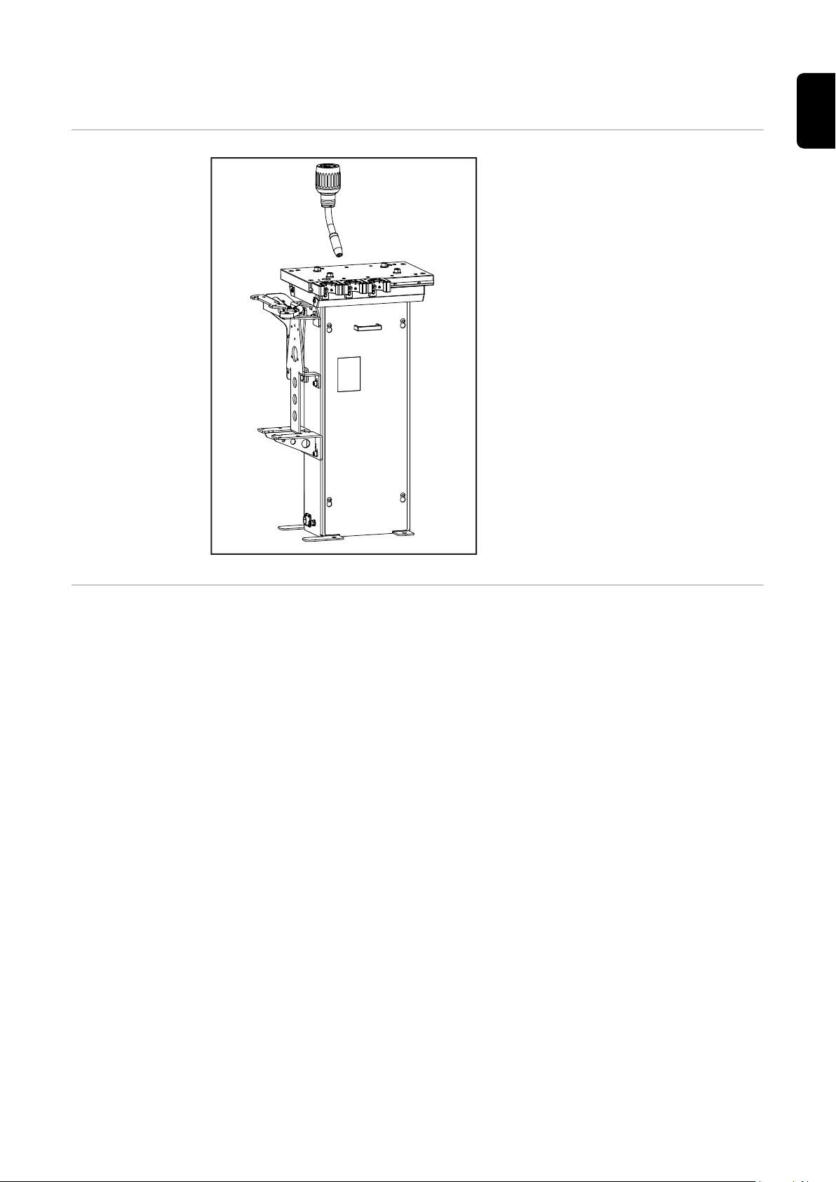
Torch body change station
(3)
(1)
(2)
(4)
(5)
(6)
(1)(2)(3)
The torch body change station is used
to:
- hold up to 10 torch bodies
- hold a welding-torch cleaning
device
- hold a wire cutter
- hold a TCP measurement system
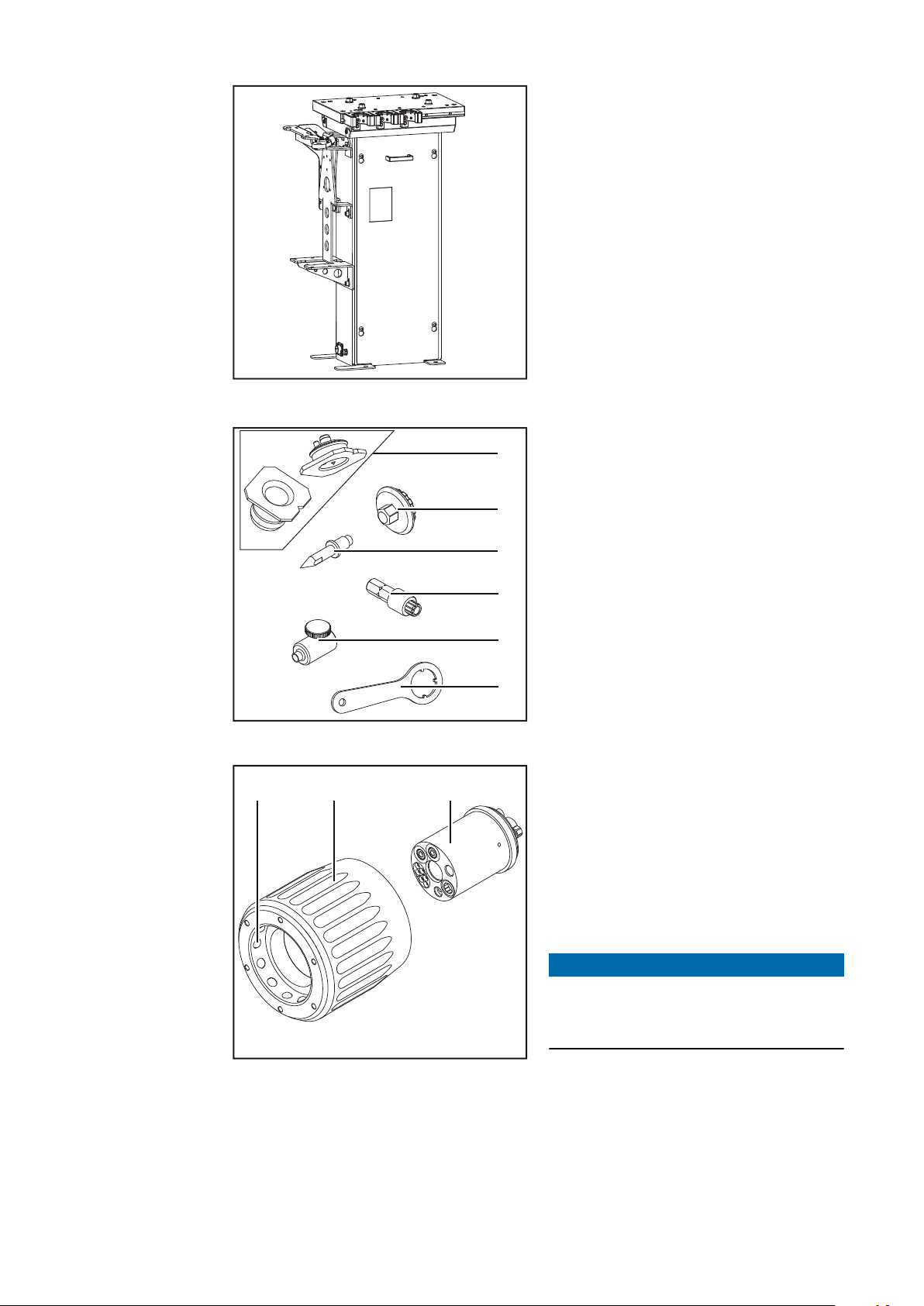
Tool kit TX/i comprising:
(1) Robot programming aid (2 parts)
(2) Installation tool for torch body
coupling TX/i
(3) 3 TCP tips
(4) Bit insert for coolant stop
(5) Cutting aid
(6) Key for fume extraction torch
body
Tool kit TX/i
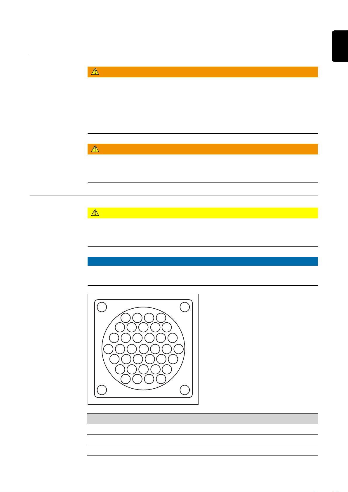
Torch body coupling, core bolt TX/i G / core bolt TX/i
W
- The core bolt (1) is for media transfer
in the torch body coupling (2)
- The torch body coupling (2) enables
the torch body to be changed
- Length of the coupling = 67.5 mm
(2.66 in.)
- The TCP moves by 47 mm (1.85
in.) with the coupling.
NOTE!
The locking balls (3) are intended for
dry operation.
Do not lubricate the locking balls.
16
Page 17

Torch body MTB G R TX / torch body MTB W R TX Wire cutter
(1)
(2)
(3)
(4)
(5)
(6)
(7)
EN
Compatible system components
for the overall
welding system
Scope of supply
Only use the torch body change system in conjunction with the following system components:
- Any power source from the TPS/i series
- Any Fronius robot wirefeeder from the WF R and WF R PAP series
- Any Fronius unreeling wirefeeder from the WF REEL R series that is synchronised
by the power source
- Any MHP R hosepack
- Any MHP RD hosepack and the associated drive units
- WF 25i Robacta Drive G, WF 25i Robacta Drive W
- WF 60i Robacta Drive CMT G, WF 60i Robacta Drive CMT W
- Any MTB G R TX and MTB W R TX torch body
- Robacta Reamer V Easy, Robacta Reamer V
- Robacta Reamer brush head Alu edition
- Any device from the Robacta TC series
(1) Torch body change station (with
3 torch-body racks in the standard version)
(2) Torch body coupling TX/i with
core bolt TX/i G or core bolt TX/i
W - depending on the system
(3) 2 wire cutter holders
(4) 4 screws for wire cutter holders
(5) 4 washers for wire cutter holders
(6) 4 adjustment plates 1 mm (0.04
inch)
(7) 4 adjustment plates 1.5 mm
(0.06 inch)
(8) Operating instructions (not
shown)
Proper use The device is intended solely for changing Fronius torch bodies.
17
Page 18

The device is intended solely for use in conjunction with Fronius system components.
This applies to the cooling units and coolant in particular - only use the device in conjunction with Fronius cooling units and Fronius coolant.
Any use above and beyond this purpose is deemed improper. The manufacturer is not
liable for any damage, inadequate or incorrect results arising out of such misuse.
Proper use also includes
- carefully reading and obeying all operating instructions and safety and danger notices
- performing all stipulated inspection and servicing work
The device is designed for use in industry and the workshop. The manufacturer shall not
be liable for any damage resulting from use of the welding torch in residential premises.
Note on wire
feeding
NOTE!
The use of wire drums is required for a perfect workflow.
18
Page 19

Warning notices on the device
24 VDC
Ser.No.
Model No.
Art.No.
U
I max
1,5 A
Pmax
6 bar
IP23
www.fronius.com
EN
Warning notices
on the device
The device is fitted with safety symbols and a rating plate. The safety symbols and rating
plate must not be removed or painted over. The symbols warn against operating the
equipment incorrectly, as this may result in serious injury and damage.
WARNING! Risk of serious injury from mechanically powered parts. Keep
the device free from current and pressure during maintenance and servicing.
Do not use the functions described here until you have thoroughly read
and understood the following documents:
- these operating instructions
- all the operating instructions for the system components, especially
the safety rules
For indoor use only
19
Page 20

Transport
Transport
devices
Transport notices
on the packaging
The device is to be transported by the following devices:
- on pallets using a forklift truck
- on pallets using a lift truck
WARNING!
Danger from equipement toppling over or falling.
This can result in serious personal injury and damage to property.
Secure the device to prevent it from falling over when transporting on a forklift truck
▶
or lift truck
Do not suddenly change direction, brake or accelerate
▶
CAUTION!
Danger due to improper transport.
This can result in damage to property.
Observe the transport notices on the device packaging.
▶
20
Page 21

Controls, connections and mechan-
ical components
21
Page 22

22
Page 23

Controls, connections and mechanical components
(5)
(4)
(3)
(2)
(1)
EN
Safety
Controls and
connections
WARNING!
Danger from incorrect operation and work that is not carried out properly.
This can result in serious personal injury and damage to property.
All the work and functions described in this document must only be carried out by
▶
technically trained and qualified personnel.
Read and understand this document in full.
▶
Read and understand all safety rules and user documentation for this device and all
▶
system components.
(1) Connection for external op-
tions
(2) Standard I/O connection for
robot control
For connecting the robot control
to the torch body change station
(3) Blanking cover
Preparation for installation of an
optional interface for connection
to the robot control
(4) Blanking cover
Preparation for installation of an optional interface for connection to the robot
control
(5) Blanking cover
Preparation for installation of an optional interface for connection to the robot
control
23
Page 24

(8)
(7)
(9)
(6)
(6) Compressed air connection
(3)
(1)
(2)
"A"
Connection to supply the torch
body change station with dry
and oil-free compressed air at
5.50 - 6.00 bar (79.77 - 87.02
psi)
- Size: 3/8" (0.375 in.)
(7) Wire sensor
Checks whether the wire electrode is protruding from the
welding torch
(8) Compressed air connection
"B"
Connection for supplying the
Fronius accessory equipment
with compressed air (wire cutters, welding-torch cleaning
devices)
Mechanical components
(9) I/O connection for accessory equipment
To connect Fronius accessory equipment to the torch body change station
(1) Rack holder
for holding up to 10 torch-body
racks
(2) Bracket
for attaching accessory equipment
(3) Torch-body rack
for depositing a torch body
24
Page 25
Pin assignments and signal descriptions
1234
9 8 7 6 5
101112131415
22 21 20 19 18 17 16
28 27 26 25 24 23
33 32 31 30 29
37 36 35 34
EN
Safety
Assignment of
standard I/O connection for robot
control
WARNING!
Danger from incorrect operation and work that is not carried out properly.
This can result in serious personal injury and damage to property.
All the work and functions described in this document must only be carried out by
▶
technically trained and qualified personnel.
Read and understand this document in full.
▶
Read and understand all safety rules and user documentation for this device and all
▶
system components.
WARNING!
Danger from machines that start up automatically.
This can result in serious personal injury and damage to property.
The device may only be powered through an Emergency Stop circuit.
▶
CAUTION!
Danger due to overcurrent.
Damage to connection supply can be the result.
Secure supply against overcurrent with a 1.5 A slow-blow fuse.
▶
To avoid faults, keep the cable between the torch body change station and the robot control as short as possible.
NOTE!
Pin Input* Output** Signal
1 X + 24 V
2 X GND
3 X Torch body sensor 1
25
Page 26

Pin Input* Output** Signal
4 X Torch body sensor 2
5 X Torch body sensor 3
6 X Torch body sensor 4
7 X Torch body sensor 5
8 X Torch body sensor 6
9 X Torch body sensor 7
10 X Torch body sensor 8
11 X Torch body sensor 9
12 X Torch body sensor 10
13 X Sensor 1st Robacta TX cover
14 X Sensor 2nd Robacta TX cover
15 X Valve 1st Robacta TX cover
16 X Valve 2nd Robacta TX cover
17 X 'C-Act. 3' signal 1
18 X Chute signal
19 X Wire sensor signal
20 X 'C-Sens. 4' signal 2
21 X 'C-Sens. 4' signal 1
22 X 'C-Sens. 22' signal 1
23 X 'C-Act. 23' signal 2
24 X Reserve relay OUT
25 X 'C-Sens. 5' signal 1
26 X Clamp gas nozzle and cleaning motor on /
Start cleaning
27 X Gas nozzle free / 'TC Ready'
28 X Gas nozzle free / cleaning motor lowered
29 X Cleaning motor running
30 X Spraying in parting agent
31 X Fill level of parting agent OK
32 X Cleaning motor up
33 X Cleaning motor lowered / 'Cleaning Error'
34 X Cleaning motor raised
35 X Cut wire electrode
26
36 X Wire cutter closed
37 X Wire cutter open
* from the torch body change station to the robot
** from the robot to the torch body change station
Page 27

Signal descriptions
Pin Signal Signal description
3 Torch body sensor 1 The respective torch body is deposited in the cor-
4 Torch body sensor 2
5 Torch body sensor 3
6 Torch body sensor 4
7 Torch body sensor 5
8 Torch body sensor 6
9 Torch body sensor 7
10 Torch body sensor 8
11 Torch body sensor 9
12 Torch body sensor 10
responding torch-body rack
EN
13 Sensor 1st Robacta TX
cover
14 Sensor 2nd Robacta TX
cover
15 Valve 1st Robacta TX
cover
16 Valve 2nd Robacta TX
cover
17 'C-Act. 3' signal 1 Reserve signal for actuator
18 Chute signal Signal only available as an option.
19 Wire sensor signal Indicates that the wire electrode is protruding from
20 'C-Sens. 4' signal 2 Reserve signal for sensor
21 'C-Sens. 4' signal 1 Reserve signal for sensor
22 'C-Sens. 22' signal 1 Reserve signal for sensor
23 'C-Act. 23' signal 1 Reserve signal for actuator
Signal only available as an option.
- 1st Robacta TX cover is open
Signal only available as an option.
- 2nd Robacta TX cover is open
Signal only available as an option.
- Opens and closes the 1st Robacta TX cover
Signal only available as an option.
- Opens and closes the 2nd Robacta TX cover
- Torch body has been deposited in the Robacta
TX chute / Robacta TX XL chute
the torch body after a successful torch body
change
24 Reserve relay OUT Reserve signal for actuator (relay contact)
25 'C-Sens. 5' signal 1 Reserve signal for sensor
26 Clamp gas nozzle and
cleaning motor on / Start
cleaning
Signal only available as an option.
"Clamp gas nozzle and cleaning motor on" signal
for Robacta Reamer V only:
- Activates the gas nozzle clamping device and
the cleaning motor
"Start cleaning" signal for Robacta Reamer
devices (excluding Robacta Reamer V), Robacta
TC devices:
- Activates the cleaning process
27
Page 28

Pin Signal Signal description
27 Gas nozzle free / 'TC
Ready'
28 Gas nozzle free / cleaning
motor lowered
29 Cleaning motor running Signal is only available for Robacta Reamer V:
30 Spraying in parting agent Signal is only available for Robacta Reamer V:
Signal only available as an option.
"Gas nozzle free" signal for Robacta Reamer V
only:
- Gas nozzle clamping device on welding-torch
cleaning device is not holding a gas nozzle
'TC Ready' signal for Robacta TC devices only:
- Welding-torch cleaning device is ready
Signal only available as an option.
"Gas nozzle free" signal for Robacta Reamer V
Easy only:
- Gas nozzle clamping device on welding-torch
cleaning device is not holding a gas nozzle
"Cleaning motor lowered" signal for Robacta
Reamer brush head Alu edition only:
- Cleaning motor was lowered
- Cleaning motor running and emitting constant
pulses
- Activates the spraying in of the parting agent
31 Fill level of parting agentOKSignal is only available for Robacta Reamer V:
- Parting agent is in the parting agent container
32 Cleaning motor up Signal is only available for Robacta Reamer V:
- Activates the upward movement of the cleaning motor
33 Cleaning motor lowered /
'Cleaning Error'
34 Cleaning motor raised Signal is only available for Robacta Reamer V:
35 Cut wire electrode Signal only available as an option:
36 Wire cutter closed Signal only available as an option:
37 Wire cutter open Signal only available as an option:
Signal only available as an option.
"Cleaning motor lowered" signal for Robacta
Reamer V and Robacta Reamer brush head Alu
edition only:
- Cleaning motor was lowered
'Cleaning Error' signal for Robacta TC devices
only:
- Error during cleaning
- Cleaning motor was raised
- Activates the wire cutter
- Wire cutter is closed
- Wire cutter is open
28
Page 29
Assignment of
1
2
3
4
5
connection to external options
CAUTION!
Danger due to overcurrent.
Damage to connection supply can be the result.
Secure supply against overcurrent with a 1.5 A slow-blow fuse.
▶
NOTE!
To avoid faults, keep the cable between the torch body change station and the robot control as short as possible.
1 + 24 V
2 GND
3 -
4 -
5 -
EN
29
Page 30

30
Page 31

Installation and commissioning
31
Page 32

32
Page 33

Safety
Safety Observe the following safety rules for all work described in the "Installation and start-up"
section.
WARNING!
Danger from incorrect operation and work that is not carried out properly.
This can result in serious personal injury and damage to property.
All the work and functions described in this document must only be carried out by
▶
technically trained and qualified personnel.
Read and understand this document in full.
▶
Read and understand all safety rules and user documentation for this device and all
▶
system components.
WARNING!
Danger due to machines that start up automatically.
This can result in serious personal injury and damage to property.
In addition to these Operating Instructions, the safety rules issued by the manufac-
▶
turer of the robot and welding system must also be observed.
For your personal safety, ensure that all protective measures have been taken and
▶
will remain in place while you are in the working area of the robot.
EN
WARNING!
Danger from the robot arm.
This can result in serious personal injury and damage to property.
Ensure there is no one else within the working area of the robot whenever work is
▶
carried out.
WARNING!
Danger from electrical current.
This can result in serious personal injury and damage to property.
Before starting work, switch off all devices and components involved and disconnect
▶
them from the grid.
Secure all devices and components involved so they cannot be switched back on.
▶
After opening the device, use a suitable measuring instrument to check that electric-
▶
ally charged components (such as capacitors) have been discharged.
WARNING!
Danger due to hot system components and/or equipment.
Can result in serious burns or scalding.
Before starting work, allow all hot system components and/or equipment to cool to
▶
+25°C/+77°F (e.g., coolant, water-cooled system components, wirefeeder drive motor, etc.)
Wear suitable protective equipment (e.g., heat-resistant gloves, safety goggles, etc.)
▶
if cooling down is not possible.
33
Page 34

WARNING!
Danger from compressed air escaping from the torch body coupling, flying parts,
and sharp components.
This can result in serious personal injury and damage to property.
During the work described below, always wear the following protective equipment:
▶
Protective goggles with side protection, Gloves - electrically insulated and providing
protection against heat, Safety helmet.
34
Page 35

Before installation and commissioning
EN
Operators, maintenance personnel
Setup regulations
WARNING!
Risk of machines starting automatically.
This can result in serious injury and damage to property.
The device must only be used by 1 person at a time. It is also necessary to ensure
▶
that no one else is within the working area of the device when the device is being
used.
The device must only be serviced by 1 person at a time. It is also necessary to en-
▶
sure that no one else is within the working area of the device when the device is being serviced.
NOTE!
The torch body change station must be incorporated into a higher-level safety system within a secured area.
If this area has to be accessed when setup and maintenance work is carried out, make
sure that
the entire system is switched off for the duration of the work in this area.
▶
and that it is prevented from starting up accidentally, for example as the result of a
▶
control fault
Compressed air
supply specifications
The device is tested to degree of protection IP 23, meaning:
- protection against penetration by solid foreign bodies with diameters > 12.5 mm
(0.49 in.)
- protection against spraywater at any angle up to 60° to the vertical
Dust
Make sure that metallic dust cannot accumulate directly on the device (for example from
grinding work).
To ensure that the torch body change system functions correctly, the following compressed air supply specifications must be met:
- Compressed air is free of oil
- Compressed air is free of dust - no dirt particles larger than 5 µm
- Compressed air is free of water
- Compressed air supply at 5.50 - 6.00 bar (79.77 - 87.02 psi)
- Minimum inner diameter of compressed air lines 5.5 mm (0.22 in.)
35
Page 36

Application example
(8)(13) (12) (10) (9)(11)
(1) (2) (3) (4)
(7) (6) (5)
Application example
NOTE!
Irrespective of the overall welding system setup
adhere to the compressed air specifications
▶
provide the compressed air supply to the torch body change station as shown
▶
(1) Interconnecting hosepack (8) Robot
(2) Wirefeeding hose (9) Wire drum
(3) Wirefeeder with "16 bar gas pur-
ging" option
(4) Torch hosepack with torch body
coupling and torch body MTB G R
TX / MTB W R TX
(5) Compressed air supply line for
torch body change station 5.50 -
6.00 bar (79.77 - 87.02 psi) - for
supplying the accessory equipment
(6) Compressed air maintenance unit
with filter
(7) Torch body change station
(10) Power source with cooling unit
(11) Data cable
(12) Data cable
(13) Robot control
36
Page 37

Installing the torch body change station
EN
Bolting the torch
body change station to the underlying surface
(foundation)
WARNING!
Danger from mechanically powered parts and escaping compressed air.
This can result in serious personal injury and damage to property.
Before starting any work, take the measures listed below and make sure that these
▶
measures remain in effect until all work is completed:
disconnect the compressed air supply line to the torch body change station from the
▶
compressed air supply
disconnect the "16 bar gas purging" option connection for the wirefeeder from the
▶
compressed air supply
NOTE!
Different fixings may be required to set up the device depending on the type of underlying surface (foundation).
Fixings are therefore not included in the scope of supply of the device. The installer is
responsible for selecting the right type of fixing.
1 2
Installing the
torch body
change station
* only use the adjustment plates if necessary
WARNING!
Danger from mechanically powered parts and escaping compressed air.
This can result in serious personal injury and damage to property.
Make sure that the compressed air supply line to the torch body change station re-
▶
mains free of compressed air until the installation and start-up are concluded
Make sure that the compressed air supply line to the "16 bar gas purging" option for
▶
the wirefeeder remains free of compressed air until the installation and start-up are
concluded .
37
Page 38

1 2
38
Page 39

Preparing the torch body
(1)
(2)
EN
Preparing torch
bodies with steel
inner liners
1
Make sure when fitting that the inner
liner (1) is pushed in as far as it will go
against the contact tip (2).
2 3
NOTE!
NOTE!
The coupling surface of the torch body must always be free of oil, grease, dust
and moisture.
39
Page 40

Preparing torch
(1)
(2)
bodies with
plastic inner
liners
1
Make sure when fitting that the inner
liner (1) is pushed in as far as it will go
against the contact tip (2).
2 3
NOTE!
NOTE!
The coupling surface of the torch body must always be free of oil, grease, dust
and moisture.
40
Page 41

Configuring the torch-body racks
EN
Safety
General
WARNING!
Danger due to mechanical moving parts moving unexpectedly.
This can result in serious personal injury and damage to property.
Before starting work, disconnect all devices and system components involved from
▶
all pneumatic and/or hydraulic supply lines and ensure that the supply lines remain
disconnected until the work is completed.
Before starting work, disconnect all devices and system components involved from
▶
the power supply and ensure that the power supply remains disconnected until the
work is completed.
- Every torch-body rack is equipped
with a locating element
- Every torch body has a groove in
which the locating element of the
torch-body rack engages when the
torch body is deposited in the torchbody rack. The torch body must always be deposited in the torch-body
rack so that the locating element of
the torch-body rack engages in the
groove in the torch body.
Some examples for orientation of the torch body at
+90°, 0°, -90°
- The locating element may be attached at various positions in the torch-body rack.
- At the factory, the locating element is attached in the torch-body rack in the 0° position - if the torch body in the 0° position is deposited in the torch-body rack, this
shows that the end of the torch body is away from the torch body change station.
- To change the orientation of the deposited torch body, the locating element may be
moved in the torch-body rack in 45° increments (-90°, -45°, 0°, +45°, +90°)
41
Page 42

Configuring the
torch-body rack
1 2
42
Page 43

Checking the torch body sensor and setting the
wire sensor
Safety
Danger due to mechanical moving parts moving unexpectedly.
This can result in serious personal injury and damage to property.
▶
▶
Connecting the
torch body
change station to
the robot control
1
EN
WARNING!
Before starting work, disconnect all devices and system components involved from
all pneumatic and/or hydraulic supply lines and ensure that the supply lines remain
disconnected until the work is completed.
Before starting work, disconnect all devices and system components involved from
the power supply and ensure that the power supply remains disconnected until the
work is completed.
NOTE!
The torch body change station can also
be connected to the robot control via a
field-bus system.
Checking the
torch body
sensor
1
2
43
Page 44

* Check that the LED lights up on the torch body sensor. If the LED does not
(2) (1)
(4) (3)
light up, check the connection between the robot control and the torch body
change station
Check all the other torch body sensors
3
Setting the wire
sensor
Rotate the wire electrode in the open-
1
ing (2) of the wire sensor (1) during
the entire setting process
- LED (4) lights up if the wire
sensor (1) detects the wire electrode
Turn the adjusting screw (3) back until
2
the LED (4) goes out
- Wire sensor is deactivated
Keep turning the adjusting screw (3)
3
only until the LED (4) lights up again
- Wire sensor (1) is now set at the
lowest sensitivity level
- This prevents the wire sensor
from being triggered accidentally
44
Page 45

Fitting the torch body coupling to the MHP R
1
2
hosepack
Safety
Fitting the torch
body coupling
WARNING!
Danger due to mechanical moving parts moving unexpectedly.
This can result in serious personal injury and damage to property.
Before starting work, disconnect all devices and system components involved from
▶
all pneumatic and/or hydraulic supply lines and ensure that the supply lines remain
disconnected until the work is completed.
Before starting work, disconnect all devices and system components involved from
▶
the power supply and ensure that the power supply remains disconnected until the
work is completed.
NOTE!
The coupling surfaces between the torch body coupling and torch body must always be free of oil, grease, dust and moisture.
EN
1 2
3 4
45
Page 46

5 6
**
*
1
1
1
***
7 8
* Steel inner liner
** Plastic inner liner
9
10
*** Screw the cap onto the inner liner
as far as it will go. The inner liner
must be visible through the hole in
the cap.
46
Page 47

Fitting the torch body coupling to the WF 25i
Robacta Drive / WF 60i Robacta Drive CMT drive
unit
Safety
Preparing the
torch body coupling for plastic inner liners
Danger due to mechanical moving parts moving unexpectedly.
This can result in serious personal injury and damage to property.
▶
▶
1
WARNING!
Before starting work, disconnect all devices and system components involved from
all pneumatic and/or hydraulic supply lines and ensure that the supply lines remain
disconnected until the work is completed.
Before starting work, disconnect all devices and system components involved from
the power supply and ensure that the power supply remains disconnected until the
work is completed.
2
EN
* use the cutting pipe from the original equipment kit for the drive unit used
3
47
Page 48

Preparing the
torch body coupling for steel inner liners
1
2
* use the cutting pipe from the original equipment kit for the drive unit used
Fitting the torch
body coupling
3
1
NOTE!
The coupling surfaces between the
torch body coupling and torch body
must always be free of oil, grease, dust
and moisture.
48
Page 49

Manually unlocking / locking the torch body coup-
(1)
(1)
ling
Manually unlocking / locking the
torch body coupling
EN
NOTE!
When the torch body coupling is unlocked, the locking balls (1) do not protrude out of the inside of the torch body
coupling.
Unlocking the torch body coupling
NOTE!
Locking the torch body coupling
When the torch body coupling is
locked, the locking balls (1) protrude
out of the inside of the torch body
coupling as shown.
NOTE!
To lock a torch body in the torch body
coupling, insert the torch body into the
unlocked torch body coupling and turn
the handle of the torch body coupling
to the right as far as it will go (end position).
Locking the torch body in the torch body coupling
If there is a torch body in the torch body
coupling, the handle of the torch body
coupling can be turned through roughly
90° before it reaches the end position.
49
Page 50

Checking the torch body coupling function
Checking the
torch body coupling function
Actuate the torch body coupling 5 times with a robot signal and check that the torch
1
body coupling opens and closes
- If the torch body coupling opens and closes correctly, then check that a torch
body can be locked in the torch body coupling manually
Torch body coupling closed Torch body coupling open
2
NOTE!
If the torch body can be locked in the
torch body coupling manually, the torch
body coupling is ready to use.
50
Page 51

Converting the torch body coupling from TX/i low
1
to TX/i high
General Robacta TX/i can be operated with a system pressure of 5-16 bar.
There are two versions here:
Robacta TX/i low
- For system pressures of 5-7.5 bar
- With vent valve in the torch body coupling
Robacta TX/i high
- For system pressures of 8-16 bar
- Without vent valve in the torch body coupling
NOTE!
Avoid pressures between 7.
5 and 8.5 bar where possible!
Converting the
torch body coupling from TX/i low
to TX/i high
The torch body coupling must be converted from TX/i low to TX/i high for pressures in
excess of 8 bar.
The vent valve is then removed as follows:
Manually unlock the torch body coup-
1
ling
(see page 49)
EN
51
Page 52

2
3
44,0450,1443
Insert fitting tool 44,0450,1443 into the
4
2
1
6
7
13 mm
5
2
torch body coupling
Unscrew the brass washer from the
3
torch body coupling
Remove the vent valve (e.g. with a
4
scriber or needle-nosed pliers or with
a 1.5 mm drill)
Insert the brass washer into the torch
5
body coupling
Insert fitting tool
6
Secure brass washer with the fitting
7
tool
52
Page 53

Setting up the robot
EN
General
Dimensions of
the rack holder
including torchbody racks
NOTE!
Before starting automated operation, set up the robot with the robot programming
aid supplied.
Determining the
TCP of the welding torch, determining the X-axis
and Y-axis of the
torch body
change station
CAUTION!
Risk of injury from razor-sharp TCP tips.
Do not touch the pointed end of the TCP tips.
53
Page 54

(1)(1)(1)
Screw 3 TCP tips into the holes (1) of
(1)
(1)
(1)
1
the rack holder
Measure TCP of the welding torch be-
2
ing used
Determine the X-axis and Y-axis of the
3
torch body change station using the
TCP tips and record in the coordinate
system of the robot
Functions of the
robot programming aid
- The notch (1) on the robot programming aid symbolises the gas nozzle of
the torch body - the gas nozzle of the
torch body would point in the same
direction as the notch (1) if there were
a torch body locked in the torch body
coupling.
- When setting up the robot, make sure
that the two parts of the robot programming aid lie flat and flush with
one another as shown.
- In automated mode, use the end position of the robot programming aid on
the respective torch-body rack as the
end position for depositing the torch
body (end position of robot programming aid on the torch-body rack = end
position of torch body in the torchbody rack).
54
Page 55

Setting up the robot
1 2
3 4
EN
5 6
55
Page 56

7
If present, set up the robot for all further torch-body racks
8
56
Page 57

Start-up
EN
Prerequisites for
start-up
Start-up The torch body change station is started up by an active signal from the robot control.
The following prerequisites must be fulfilled for start-up:
- Torch body change station installed
- All torch body sensors checked and wire sensor set
- All torch bodies prepared
- Torch body coupling fitted
- Torch bodies oriented for special rack positions (only if necessary)
- Torch body coupling function checked
- Robot set up using robot programming aid
57
Page 58

Program sequence
Safety
Speed data for
the program sequence
CAUTION!
Danger from incomplete installations.
This can result in serious damage to property.
Do not start in automated mode until the torch body change system has been prop-
▶
erly installed and started up.
A list of all speeds and corresponding units in the program sequence:
cm/min m/s ipm
1000 = 0.17 = 393.70
600 = 0.1 = 236.22
100 = 0.017 = 39.37
70 = 0.012 = 27.56
50 = 0.008 = 19.69
35 = 0.006 = 13.78
30 = 0.005 = 11.81
10 = 0,0017 = 3.94
Subprograms in
the program sequence
To facilitate programming, the program sequence is split into the following subprograms:
- Cut wire electrode
- Wind back wire electrode
- Deposit torch body
- Pick up torch body
- Advance wire electrode
- Cut wire electrode
58
Page 59

Program sequence
EN
Start
Move to pos. A
- above torch-body rack
Query power
source ready
'True'
Set
- Select job to advance wire electrode
- Feeder inching speed:
600 cm/min (236.22 ipm)
Move to pos. B
- approx. 25 mm (0.98 in.) next
to the wire cutter
Set
- "Advance wire electrode" signal
Cut wire electrode
- Signal duration: 2 seconds
Query wire cutter
open
'False'
'False'
Stop program
- Power source error
Reset
- "Cut wire" signal
'True'
Move to pos. C
Enter wire cutter
Set
- "Cut wire electrode" signal
Wait 0.5 seconds
'True'
Query wire cutter
open
'False'
Stop program
- Wire cutter error
59
Page 60

- 5 mm (0.2 in.) above wire cutter
(continued)
Cut wire electrode
"Cut wire electrode" signal
- "Wind back wire electrode" signal
- Wind back wire electrode until
behind coupling point
- Feeder inching speed:
Wind back
wire electrode
600 cm/min (236.22 ipm)
- Signal duration: calculated using
torch body length
Query wire
cutter
closed
'True'
Move to pos. D
Reset
Set
'False'
Stop program
- Wire cutter error
Move to pos. E
Above the rack positions
Query torch
body sensor
(torch-body rack
empty)
'False'
Set
- "Valve 1st Robacta TX cover" signal
Deposit torch body
Query
sensor 1st
Robacta TX
cover
TX
'True'
Wait 10
seconds
Stop program
- Torch body change error
Stop program
'False'
- Robacta TX cover
error
60
'True'
Move to pos. F
- 50 mm (1.97 in.) next to centre of
torch-body rack
- 75 mm (2.95 in.) above top of torchbody rack
Only with Robacta TX cover option
Page 61

Move to pos. G
- Insert 75 mm (2.95 in.) above
centre of torch-body rack
- Speed:
max. 100 cm/min (39.37 ipm)
Move to pos. H
- Move down into torch-body rack
Speed:
max. 50 cm/min (19.69 ipm)
Wait 0.5 seconds
Query torch body
sensor (torch body
inserted into torch-body
rack)
'True'
Wait 0.5
seconds
'False'
EN
Stop inserting into torch-
body rack
Stop program
- Torch body change
error
Stop
Insert into torch-body rack
Set
Deposit torch body (continued)
- "Change torch body" signal
Wait 2.5 seconds
Move to pos. I
- Raise 25 mm (0.98 in.) above
centre of torch-body rack
- Speed:
max. 30 cm/min (11.81 in.)
Move to pos. J
- Raise 75 mm (2.95 in.) above
centre of torch-body rack
- Speed: high speed
61
Page 62

Wait 0.5 seconds
Query
torch body
sensor (new
torch body
present)
'True'
Move to pos. K
- 75 mm (2.95 in.) above centre of
torch body to be picked up
Query torch
body sensor
'True'
Reset
- "Valve 1st Robacta TX cover"
signal
'False'
'False'
Stop program
- Torch body change error
Stop program
- Torch body change error
Pick up torch body
Query sensor
1st Robacta TX
- "Valve 2nd Robacta TX cover"
Query sensor
2nd Robacta TX
cover
'False'
Set
signal
cover
'True'
Wait 10
seconds
Wait 10
seconds
'True'
'False'
Stop program
- Robacta TX cover
error
Stop program
- Robacta TX cover
error
62
Page 63

Move to pos. L
- 25 mm (0.98 in.) above centre of torch
body to be picked up
Move to pos. M
- Pick up torch body flush
- Speed: max. 100 cm/min (39.37 ipm)
Reset
- "Change torch body" signal
Wait 2 - 3 seconds
Move to pos. N
- Raise 75 mm (2.95 in.) above centre
of torch-body rack
- Speed: max. 100 cm/min (39.37 ipm)
EN
Pick up torch body (continued)
Wait 0.5 seconds
Query torch body
sensor (torch body
successfully
picked up)
'False'
'True'
Stop program
- Torch body change error
63
Page 64

Move to pos. O
- 75 mm (2.95 in.) above top of torchbody rack
- 50 mm (1.97 in.) next to centre of
torch-body rack
- Speed: max. 1000 cm/min (393.70
ipm)
Reset
- "Valve 2nd Robacta TX cover" signal
Pick up torch body (continued)
- Align gas nozzle approx. 10 mm
(0.39 in.) above centre of wire sensor
- "Advance wire electrode" signal
Query sensor
2nd Robacta TX
cover
'False'
Move to pos. P
Set
- Feeder inching speed:
600 cm/min (236.22 ipm)
Wait 10
seconds
Only with Robacta TX cover option
Stop program
'True'
- Robacta TX cover
error
Query wire
sensor (wire
electrode
Advance wire electrode
- "Advance wire electrode" signal
- approx. 25 mm (0.98 in.) next to the
Cut
wire electrode
present)
'True'
Reset
Move to pos. B
wire cutter
Wait 10
seconds
'False'
Reset
- "Advance wire
electrode" signal
Stop program
- Torch body change
error
64
Page 65

Set
- "Advance wire electrode" signal
- Signal duration: 1 second
EN
- Enter wire cutter
- "Cut wire electrode"
Wait 0.5 seconds
Cut wire electrode
Query wire
cutter open
'True'
Move to pos. C
Set
signal
Query wire
cutter closed
'False'
'True'
'False'
Reset
- "Cut wire" signal
Query wire
cutter open
'False'
Stop program
- Wire cutter error
Stop program
- Wire cutter error
'True'
Move to pos. D
- 5 mm (0.2 in.) above wire cutter
Reset
- "Cut wire electrode" signal
Query power
source ready
'True'
End
'False'
Stop program
- Torch body change error
65
Page 66

66
Page 67

Options
67
Page 68

68
Page 69

Safety
Safety Observe the following safety rules for all work described in the "Options" section.
WARNING!
Danger from incorrect operation and work that is not carried out properly.
This can result in serious personal injury and damage to property.
All the work and functions described in this document must only be carried out by
▶
technically trained and qualified personnel.
Read and understand this document in full.
▶
Read and understand all safety rules and user documentation for this device and all
▶
system components.
WARNING!
Danger from machines that start up automatically.
This can result in serious personal injury and damage to property.
In addition to these operating instructions, the safety rules issued by the manufac-
▶
turer of the robot and welding system must also be observed.
For your personal safety, ensure that all protective measures have been taken and
▶
will remain in place while you are in the working area of the robot.
EN
WARNING!
Danger from the robot arm.
This can result in serious personal injury and damage to property.
Ensure there is no one else within the working area of the robot whenever work is
▶
carried out.
WARNING!
Danger from mechanically powered parts and escaping compressed air.
This can result in serious personal injury and damage to property.
disconnect the torch body change station from the compressed air supply
▶
disconnect the torch body change station from the power supply
▶
disconnect the "16 bar gas purging" option connection for the wirefeeder from the
▶
compressed air supply
make sure that these measures remain in effect until all work is completed.
▶
WARNING!
Danger from electrical current.
This can result in serious personal injury and damage to property.
Before starting work, switch off all devices and components involved and disconnect
▶
them from the grid.
Secure all devices and components involved so they cannot be switched back on.
▶
After opening the device, use a suitable measuring instrument to check that electric-
▶
ally charged components (such as capacitors) have been discharged.
69
Page 70

WARNING!
Danger due to mechanical moving parts moving unexpectedly.
This can result in serious personal injury and damage to property.
Before starting work, disconnect all devices and system components involved from
▶
all pneumatic and/or hydraulic supply lines and ensure that the supply lines remain
disconnected until the work is completed.
Before starting work, disconnect all devices and system components involved from
▶
the power supply and ensure that the power supply remains disconnected until the
work is completed.
WARNING!
Danger from compressed air escaping from the torch body coupling, flying parts
and sharp components.
This can result in serious personal injury and damage to property.
During the work described below, always wear the following protective equipment:
▶
protective goggles with side protection, gloves - electrically insulated and providing
protection against heat, Safety helmet.
70
Page 71

Fitting the torch-body rack
EN
Fitting the torchbody rack
1 2
3 4
5 6
NOTE!
Connect the torch-body rack to the torch body change station as shown in the circuit diagram.
71
Page 72

7 8
9
72
Page 73

Fitting the compressed air maintenance unit
EN
Fitting the compressed air maintenance unit
1 2
73
Page 74

Fitting the wire cutter
Fitting the wire
cutter
1
* Use the screws supplied with the torch body change station
3 4
2
74
Page 75

Fitting the Robacta Reamer V Easy, Robacta Reamer brush head Alu edition
Fitting the
Robacta Reamer
V Easy, Robacta
Reamer brush
head Alu edition
1
3 4
EN
2
75
Page 76

Fitting the Robacta Reamer V
Fitting the
Robacta Reamer
V
1
3 4
2
76
Page 77

Connecting the torch body change station to the
Robacta TC 1000 / Robacta TC 2000
Connecting the
torch body
change station to
the Robacta TC
1000 / Robacta
TC 2000
1
* Use the screws supplied with the torch body change station
3
2
EN
4
77
Page 78

Installing the pneumatic Robacta TX cover
Installing the
pneumatic
Robacta TX cover
1 2
3
4
NOTE!
Reuse the two screws shown to screw
down the pneumatic cover - just the
screws, not the washers.
78
Page 79

5 6
7 8
EN
9
NOTE!
Connect the cover connectors to the
PC board in the torch body change station as shown in the circuit diagram.
79
Page 80

10 11
12
If present, install the second cover in the same way
13
14 15
80
Page 81

Troubleshooting
81
Page 82

82
Page 83

Safety
Safety Observe the following safety rules for all work described in the "Troubleshooting" section.
WARNING!
Danger from incorrect operation and work that is not carried out properly.
This can result in serious personal injury and damage to property.
All the work and functions described in this document must only be carried out by
▶
technically trained and qualified personnel.
Read and understand this document in full.
▶
Read and understand all safety rules and user documentation for this device and all
▶
system components.
WARNING!
Danger from machines that start up automatically.
This can result in serious personal injury and damage to property.
In addition to these Operating Instructions, the safety rules issued by the manufac-
▶
turer of the robot and welding system must also be observed.
For your personal safety, ensure that all protective measures have been taken and
▶
will remain in place while you are in the working area of the robot.
EN
WARNING!
Danger from the robot arm.
This can result in serious personal injury and damage to property.
Ensure there is no one else within the working area of the robot whenever work is
▶
carried out.
WARNING!
Danger from mechanically powered parts and escaping compressed air.
This can result in serious personal injury and damage to property.
Disconnect the torch body change system from the compressed air supply
▶
Disconnect the torch body change system from the power supply
▶
Disconnect the connection for the "16 bar gas purging" option of the wirefeeder from
▶
the compressed air supply
Make sure that these measures remain in effect until all work is completed.
▶
WARNING!
Danger from electrical current.
This can result in serious personal injury and damage to property.
Before starting work, switch off all devices and components involved and disconnect
▶
them from the grid.
Secure all devices and components involved so they cannot be switched back on.
▶
After opening the device, use a suitable measuring instrument to check that electric-
▶
ally charged components (such as capacitors) have been discharged.
83
Page 84

WARNING!
Danger due to hot system components and/or equipment.
Can result in serious burns or scalding.
Before starting work, allow all hot system components and/or equipment to cool to
▶
+25°C/+77°F (e.g., coolant, water-cooled system components, wirefeeder drive motor, etc.)
Wear suitable protective equipment (e.g., heat-resistant gloves, safety goggles, etc.)
▶
if cooling down is not possible.
WARNING!
Danger from compressed air escaping from the torch body coupling, flying parts
and sharp components.
This can result in serious personal injury and damage to property.
During the work described below, always wear the following protective equipment:
▶
protective goggles with side protection, gloves - electrically insulated and providing
protection against heat, Safety helmet.
84
Page 85

Troubleshooting
EN
Troubleshooting
Only for a water-cooled welding torch: After a torch body has been changed, there
is some residual coolant on the torch body
Cause:
Remedy:
Cause:
Remedy:
Cause:
Remedy:
Only for a water-cooled welding torch: After the torch body has been deposited,
coolant sprays out of the torch body
Cause:
Remedy:
Torch body coupling does not open
Cause:
Remedy:
Torch body coupling is worn
Send the torch body coupling to the manufacturer's service department
Compressed air escaping from the torch body coupling is causing coolant to
be blown out of the deposited torch body when the torch body coupling is
locked
Do not lock the torch body coupling until it is beside the torch body change
station
Robot speed too fast when picking up and depositing the torch body
Reduce robot speed when picking up and depositing the torch body
Torch body is very hot
Use water-cooled gas nozzle
Compressed air supply to torch body coupling is too low
Ensure compressed air supply is as per the specifications in the operating
instructions
Torch body coupling does not open
Cause:
Remedy:
Torch body coupling is faulty
Unlock the torch body coupling manually and send the torch body coupling
to the manufacturer's service department.
85
Page 86

86
Page 87

Care, maintenance and disposal
87
Page 88

88
Page 89

Safety
Safety Observe the following safety rules for all work described in the "Care, maintenance and
disposal" section.
WARNING!
Danger from incorrect operation and work that is not carried out properly.
This can result in serious personal injury and damage to property.
All the work and functions described in this document must only be carried out by
▶
technically trained and qualified personnel.
Read and understand this document in full.
▶
Read and understand all safety rules and user documentation for this device and all
▶
system components.
WARNING!
Danger from machines that start up automatically.
This can result in serious personal injury and damage to property.
In addition to these Operating Instructions, the safety rules issued by the manufac-
▶
turer of the robot and welding system must also be observed.
For your personal safety, ensure that all protective measures have been taken and
▶
will remain in place while you are in the working area of the robot.
EN
WARNING!
Danger from the robot arm
This can result in serious personal injury and damage to property.
Ensure there is no one else within the working area of the robot whenever work is
▶
carried out.
WARNING!
Danger from mechanically powered parts and escaping compressed air.
This can result in serious personal injury and damage to property.
Disconnect the torch body change system from the compressed air supply
▶
Disconnect the torch body change system from the power supply
▶
Disconnect the connection for the "16 bar gas purging" option of the wirefeeder from
▶
the compressed air supply
Make sure that these measures remain in effect until all work is completed.
▶
WARNING!
Danger from electrical current.
This can result in serious personal injury and damage to property.
Before starting work, switch off all devices and components involved and disconnect
▶
them from the grid.
Secure all devices and components involved so they cannot be switched back on.
▶
After opening the device, use a suitable measuring instrument to check that electric-
▶
ally charged components (such as capacitors) have been discharged.
89
Page 90

WARNING!
Danger due to hot system components and/or equipment.
Can result in serious burns or scalding.
Before starting work, allow all hot system components and/or equipment to cool to
▶
+25°C/+77°F (e.g., coolant, water-cooled system components, wirefeeder drive motor, etc.)
Wear suitable protective equipment (e.g., heat-resistant gloves, safety goggles, etc.)
▶
if cooling down is not possible.
WARNING!
Danger from compressed air escaping from the torch body coupling, flying parts
and sharp components.
This can result in serious personal injury and damage to property.
During the work described below, always wear the following protective equipment:
▶
protective goggles with side protection, gloves - electrically insulated and providing
protection against heat, Safety helmet.
90
Page 91

Replacing the inner liner in the torch body
(1)
(2)
EN
Replacing a steel
inner liner in the
torch body
Removing the torch body from the torch body coupling
1
2 3
4
5
NOTE!
When refitting, make sure that the inner
liner (1) is pushed in as far as it will go
against the contact tip (2).
91
Page 92

6 7
NOTE!
The coupling surface of the torch body must always be free of oil, grease, dust
and moisture.
Replacing a
plastic inner liner
in the torch body
Removing the torch body from the torch body coupling
1
2 3
4
92
Page 93

(1)
(2)
5
NOTE!
When refitting, make sure that the inner
liner (1) is pushed in as far as it will go
against the contact tip (2).
6 7
EN
NOTE!
The coupling surface of the torch body must always be free of oil, grease, dust
and moisture.
93
Page 94

Replacing the inner liner in the core bolt
Replacing a steel
inner liner in the
core bolt
Removing the torch body from the torch body coupling
1
Unscrew the torch body coupling from the drive unit
2
3
4
* use the cutting pipe from the ori-
ginal equipment kit for the drive
unit used
Replacing a
plastic inner liner
in the core bolt
94
Fit the torch body coupling correctly on the drive unit
5
(see section "Fitting the torch body coupling to the WF 25i Robacta Drive / WF 60i
Robacta Drive CMT drive unit", depending on which hosepack is used)
Removing the torch body from the torch body coupling
1
Unscrew the torch body coupling from the drive unit
2
Page 95

3
4
* use the cutting pipe from the ori-
ginal equipment kit for the drive
unit used
EN
Fit the torch body coupling correctly on the drive unit
5
(see section "Fitting the torch body coupling to the WF 25i Robacta Drive / WF 60i
Robacta Drive CMT drive unit", depending on which hosepack is used)
95
Page 96

Replacing the inner liner in the MHP R hosepack
1
2
1
2
**
*
1
1
1
Replacing the inner liner
Removing the torch body from the torch body coupling
1
Disconnect the hosepack from all system components
2
For water-cooled hosepacks: Close the coolant connections on the hosepack with
3
the cover provided
4 5
6 7
8
9
96
Page 97

10
***
11
* Steel inner liner
** Plastic inner liner
*** Screw the cap onto the inner liner as far as it will go. The inner liner must be vis-
ible through the hole in the cap.
12
EN
Connect the hosepack to the system components once more
13
97
Page 98

Replacing the O-rings in the torch body coupling
Replacing the Orings in the torch
body coupling
Removing the torch body from the torch body coupling
1
Unscrew the torch body coupling from the drive unit / hosepack
2
3 4
Fit the torch body coupling correctly on the hosepack / drive unit
5
(see section "Fitting the torch body coupling to the MHP R hosepack" or "Fitting the
torch body coupling to the WF 25i Robacta Drive / WF 60i Robacta Drive CMT drive
unit", depending on which hosepack is used)
98
Page 99

Changing coolant stops
EN
Replacing
coolant stops
Removing the torch body from the torch body coupling
1
Unscrew the torch body coupling from the drive unit / hosepack
2
Remove the core bolt from the torch body coupling
3
4 5
6 7
Fit the torch body coupling correctly on the hosepack / drive unit
8
(see section "Fitting the torch body coupling to the MHP R hosepack" or "Fitting the
torch body coupling to the WF 25i Robacta Drive / WF 60i Robacta Drive CMT drive
unit", depending on which hosepack is used)
99
Page 100

Disposal
Disposal Dispose of in accordance with the applicable national and local regulations.
100
 Loading...