

Page 1

Operating
instructions
Robacta Twin Compact
Operating instructions
EN
ZH
操作说明书
42,0410,2043 012-30052022
Page 2

Page 3

Contents
Safety 4
Safety 4
Start-up 6
Device concept 6
Fitting the mounting bracket (standard) 6
Fitting the mounting bracket (individually) 7
Mount robot torch neck 8
Fitting the wire guide core 8
Connect robot hosepack 10
Robacta Twin Compact Pro - Replacing components 11
Care, maintenance and disposal 12
General 12
Every time before starting up 12
Every time the wirespool is exchanged 12
Disposal 12
Troubleshooting 13
Troubleshooting 13
Technical data 18
Torch necks 18
Hosepacks 20
EN
3
Page 4

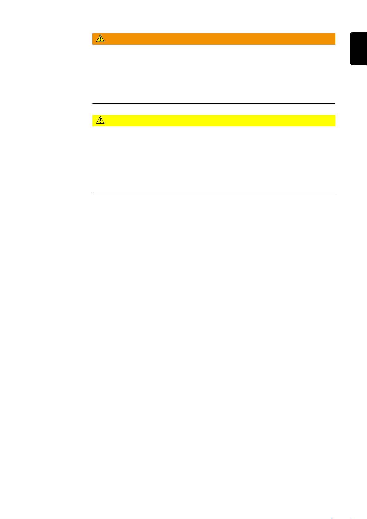
Safety
Safety
WARNING!
Danger from incorrect operation and work that is not carried out properly.
This can result in serious personal injury and damage to property.
All the work and functions described in this document must only be carried
▶
out by technically trained and qualified personnel.
Read and understand this document in full.
▶
Read and understand all safety rules and user documentation for this device
▶
and all system components.
WARNING!
Danger from electrical current.
This can result in serious personal injury and damage to property.
Before starting work, switch off all devices and components involved and dis-
▶
connect them from the grid.
Secure all devices and components involved so they cannot be switched back
▶
on.
WARNING!
Danger from electric current due to defective system components and incorrect operation.
This can result in serious personal injury and damage to property.
All cables, leads and hosepacks must always be securely connected, undam-
▶
aged and correctly insulated.
Only use adequately dimensioned cables, leads and hosepacks.
▶
WARNING!
Risk of coolant escaping.
This can result in serious personal injury and damage to property.
When disconnecting a welding torch from the cooling unit or other system
▶
components, always seal the coolant hoses using the plastic seal attached to
the torch.
WARNING!
Danger due to hot system components and/or equipment.
Can result in serious burns or scalding.
Before starting work, allow all hot system components and/or equipment to
▶
cool to +25°C/+77°F (e.g., coolant, water-cooled system components,
wirefeeder drive motor, etc.)
Wear suitable protective equipment (e.g., heat-resistant gloves, safety
▶
goggles, etc.) if cooling down is not possible.
4
Page 5
WARNING!
Danger from contact with toxic welding fumes.
This can result in serious personal injuries.
Always extract welding fumes.
▶
Ensure an adequate supply of fresh air. Ensure that there is a ventilation rate
▶
of at least 20 m³ (169070.1 US gi) per hour at all times.
If in doubt, a safety engineer should be commissioned to check the pollution
▶
level in the workplace.
CAUTION!
Danger from operation without coolant.
This can result in damage to property.
Never operate water-cooled welding torches without coolant.
▶
During welding, ensure that the coolant is circulating correctly – this will be
▶
the case for Fronius cooling units if a regular return flow of coolant can be
seen in the coolant container of the cooling unit.
The manufacturer will not be liable for any damages due to non-observance
▶
of the above mentioned points. All claims against the warranty are void.
EN
5
Page 6

Start-up
Reibahle /
Reamer /
Alésoir /
Alesatore /
Escariador /
Alar gador
Ø6G7
Bohrer /
Drill /
Foret /
Punta del
trapano /
Broca /
Broca
Ø5,8
Device concept The robot hosepack Robacta Twin Compact is distinguished by small dimensions
for the best possible accessibility to weld seams, low weight and high temperature stability. Through a closed gas conduit the gas is led to the robot torch neck
free from loss. In addition, the robot hosepack Robacta Twin Compact is
equipped with a separate compressed air piping for purging the robot torch neck.
The robot torch neck Robacta Twin Compact possesses a revolutionary connection system and is distinguished by small dimensions and so the best possible accessibility. By the water-cooled gas nozzle the system is suitable for the
MIG/MAG high-performance welding.
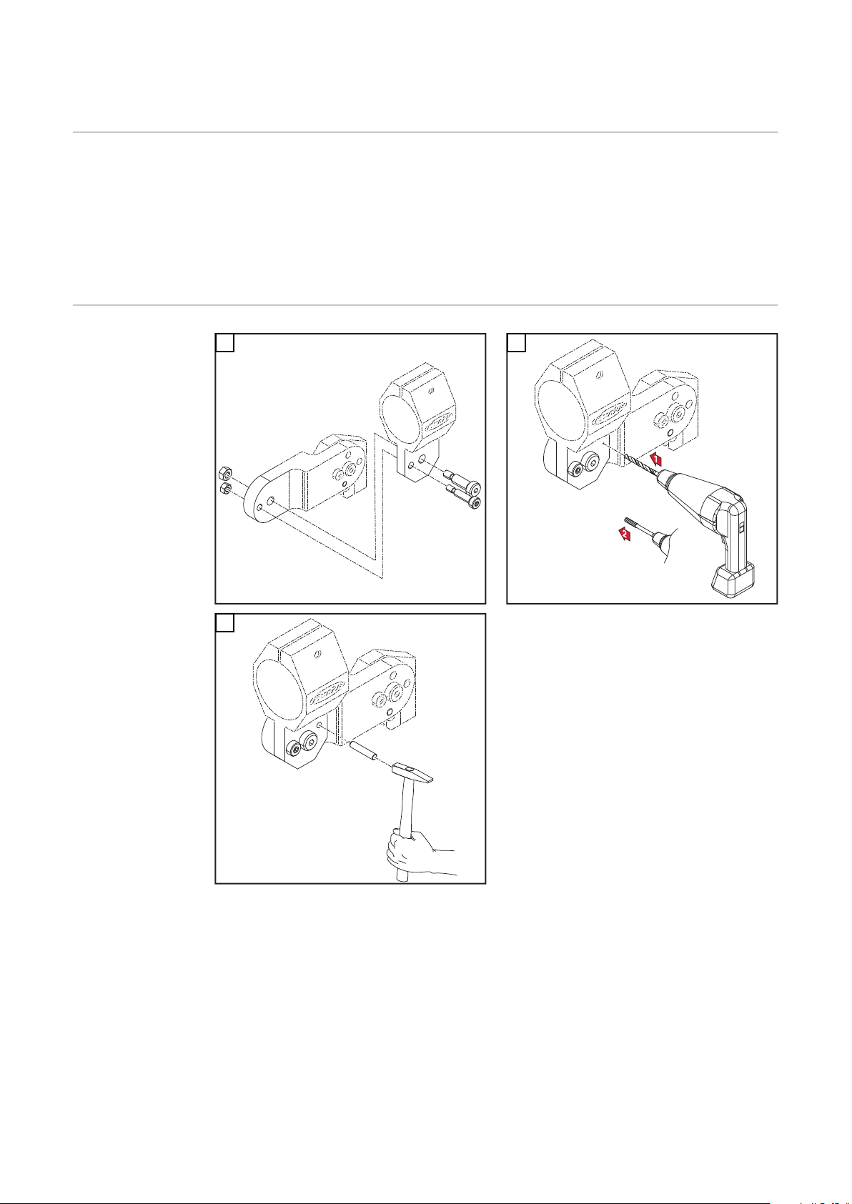
Fitting the
mounting bracket (standard)
1
3
2
IMPORTANT! Drill a Ø5.8 mm hole for the mounting bracket and use a reamer to
enlarge the hole so it can accommodate the dowel pin (Ø6G7).
IMPORTANT! The mounting bracket must be fitted using an M8 shoulder screw
and an M6 screw. After screwing the mounting bracket in place, another dowel
pin (Ø6 mm) must be driven in to secure it.
6
Page 7

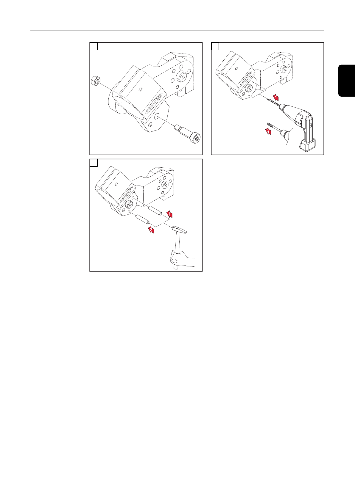
Fitting the
Reibahle /
Reamer /
Alésoir /
Alesatore /
Escariador /
Alar gador
Ø6G7
Bohrer /
Drill /
Foret /
Punta del
trapano /
Broca /
Broca
Ø5,8
mounting bracket (individually)
1
2
EN
3
IMPORTANT! Drill a Ø5.8 mm hole for the mounting bracket and use a reamer to
enlarge the hole so it can accommodate the dowel pin (Ø6G7).
IMPORTANT! The mounting bracket must be fitted using an M8 shoulder screw.
The required bracket must then be positioned and two dowel pins (Ø6 mm) driven in to secure it.
7
Page 8
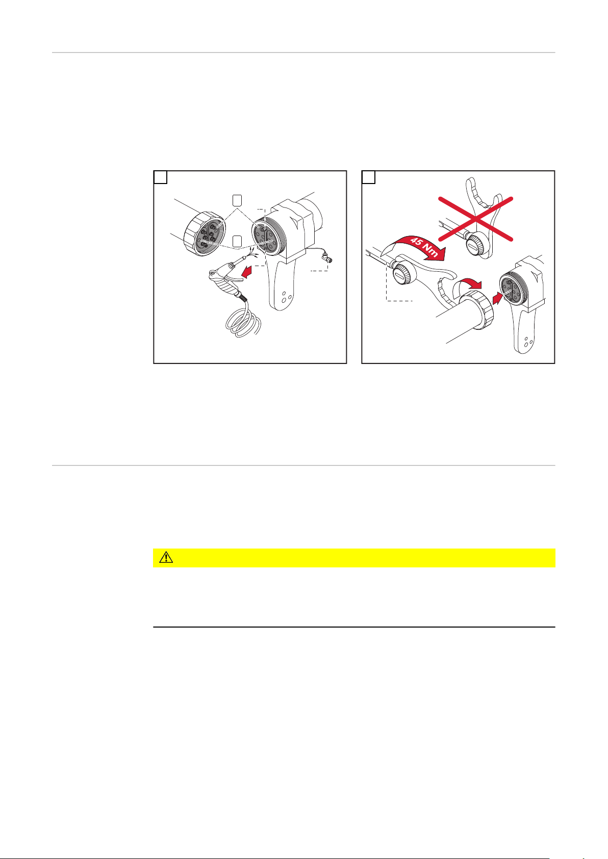
Mount robot
*
**
***
1
2
****
2
1
torch neck
IMPORTANT! Risk of serious damage to pipe bends and hosepack.
During installation, ensure that the grey contact surfaces remain totally free
-
of any contamination. If necessary, clean contact surfaces with dry reduced
compressed air.
The pipe bends must be tightened to the specified torque.
-
If a contact point is damaged, both the pipe bend and the hosepack must be
-
replaced.
1
* Centering pin
** Contact Touch Sensing
*** Connection plug switch-off box
***** The torques specified are applicable exclusively to the torque wrench op-
tionally available. See spare parts list for item number
2
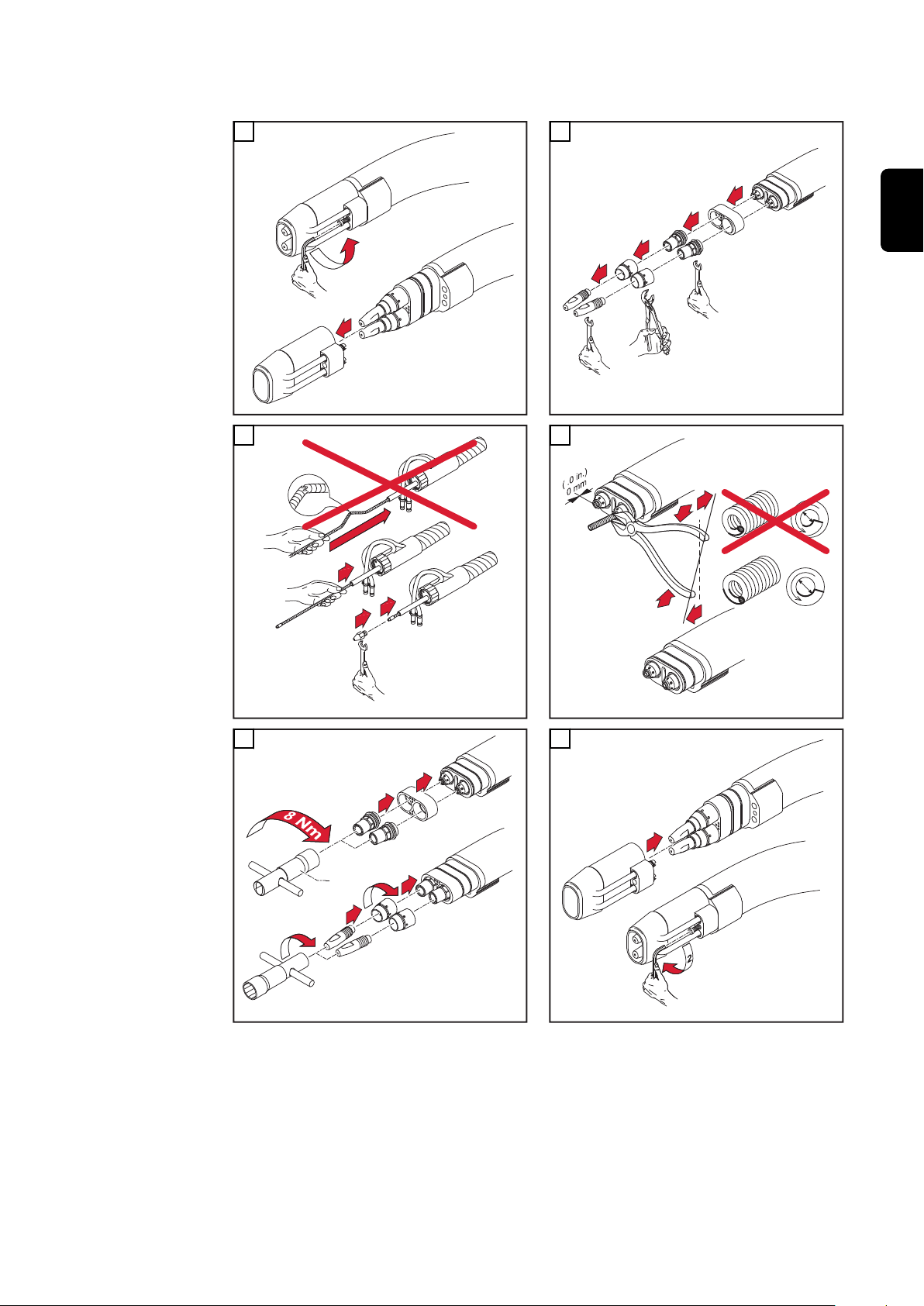
Fitting the wire
guide core
IMPORTANT! When cutting the wire guide core, ensure that:
no burr juts out into the wire guide core on cutting
-
place the side cutter slightly at an angle (burr is pulled outward)
-
grind the burr off
-
CAUTION!
Danger from work that is not carried out properly.
This can result in serious damage to property.
It is imperative that the sequence of work steps is complied with and the
▶
torques specified adhered to.
* A torque wrench and the matching socket wrench are available instead of the
tool supplied as standard. This ensures that it is possible to tighten the components with the torque specified. See spare parts list for item number.
8
Page 9

1
2
1
1
2
3
4
2
3
1
1
1
2
3
*
1
2
4
3
1
2
EN
3
5
4
6
9
Page 10
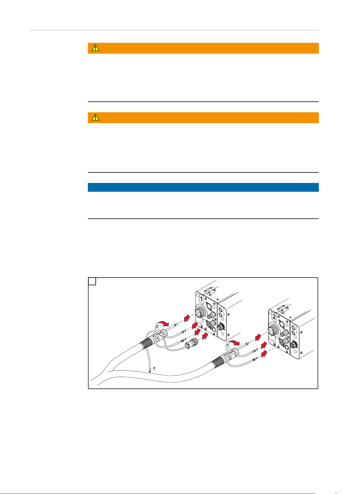
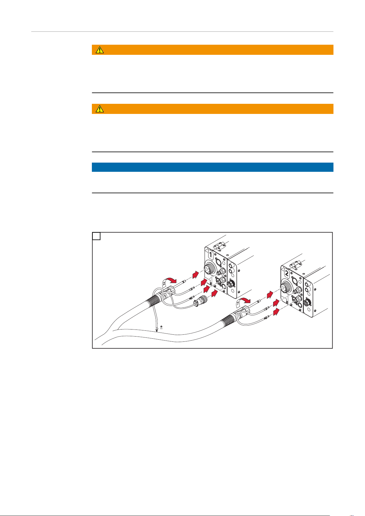
Connect robot
1
3
4
5
6
8
9
hosepack
WARNING!
Danger from electrical current.
This can result in serious personal injury and damage to property.
Before starting work, switch off all devices and components involved and dis-
▶
connect them from the grid.
Secure all devices and components involved so they cannot be switched back
▶
on.
WARNING!
Danger from electric current due to defective system components and incorrect operation.
This can result in serious personal injury and damage to property.
All cables, leads and hosepacks must always be securely connected, undam-
▶
aged and correctly insulated.
Only use adequately dimensioned cables, leads and hosepacks.
▶
NOTE!
Never start welding with a water-cooled torch if there is no coolant in the system! Fronius will not be liable for any resulting damage, and all warranty claims
shall be null and void.
IMPORTANT! Shielding gas mixed with extraneous air has an adverse effect on
welding results.
The end of the hose must be sealed off with the stopper supplied if the torch
-
blow-off connection is not in use
Do not connect the hose if no compressed air is connected to the solenoid
-
valve for the blow-off function. Seal hose with stopper.
1
* Connection for option Purge welding torch
10
Page 11
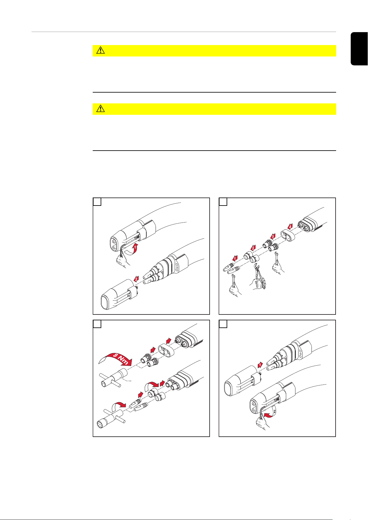
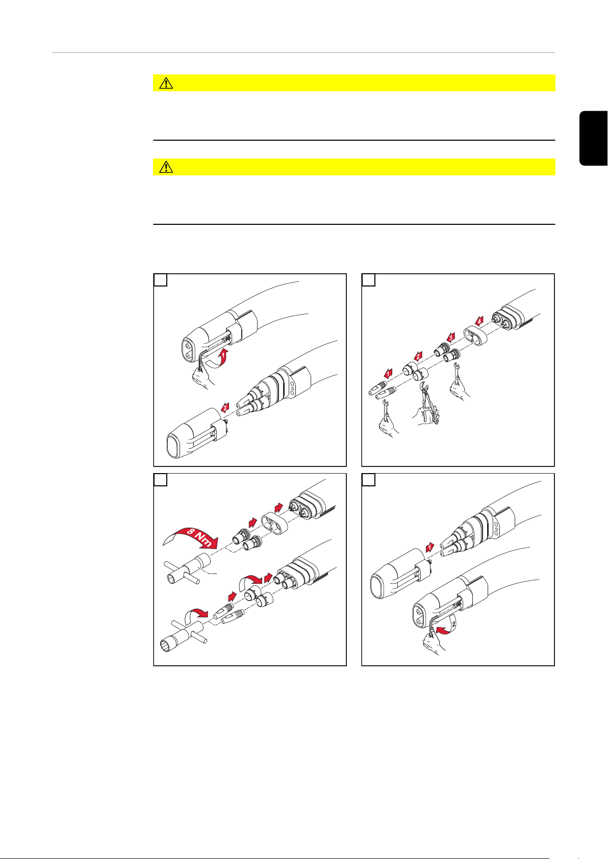
Robacta Twin
1
2
3
4
*
Compact Pro Replacing components
CAUTION!
Danger of burning by strongly heated welding torch or hot coolant.
This can result in severe scalds.
The exchange of the components as well as the cleaning and check of the
▶
components may only occur in the cooled-down state of the welding torch.
CAUTION!
Danger due to incorrect operation and incorrectly performed work.
This can result in serious damage to property.
It is imperative that the sequence of work steps is complied with and the
▶
torques specified adhered to.
* A torque wrench and the matching socket wrench are available instead of
the tool supplied as standard. This ensures that it is possible to tighten
the components with the torque specified. See spare parts list for item
number.
1 2
EN
3 4
11
Page 12
Care, maintenance and disposal
General Regular preventive maintenance of the welding torch is essential if troublefree
operation is to be ensured. The welding torch is subjected to high temperatures
and heavy soiling. For this reason, the torch needs more frequent maintenance
than other components of the welding system.
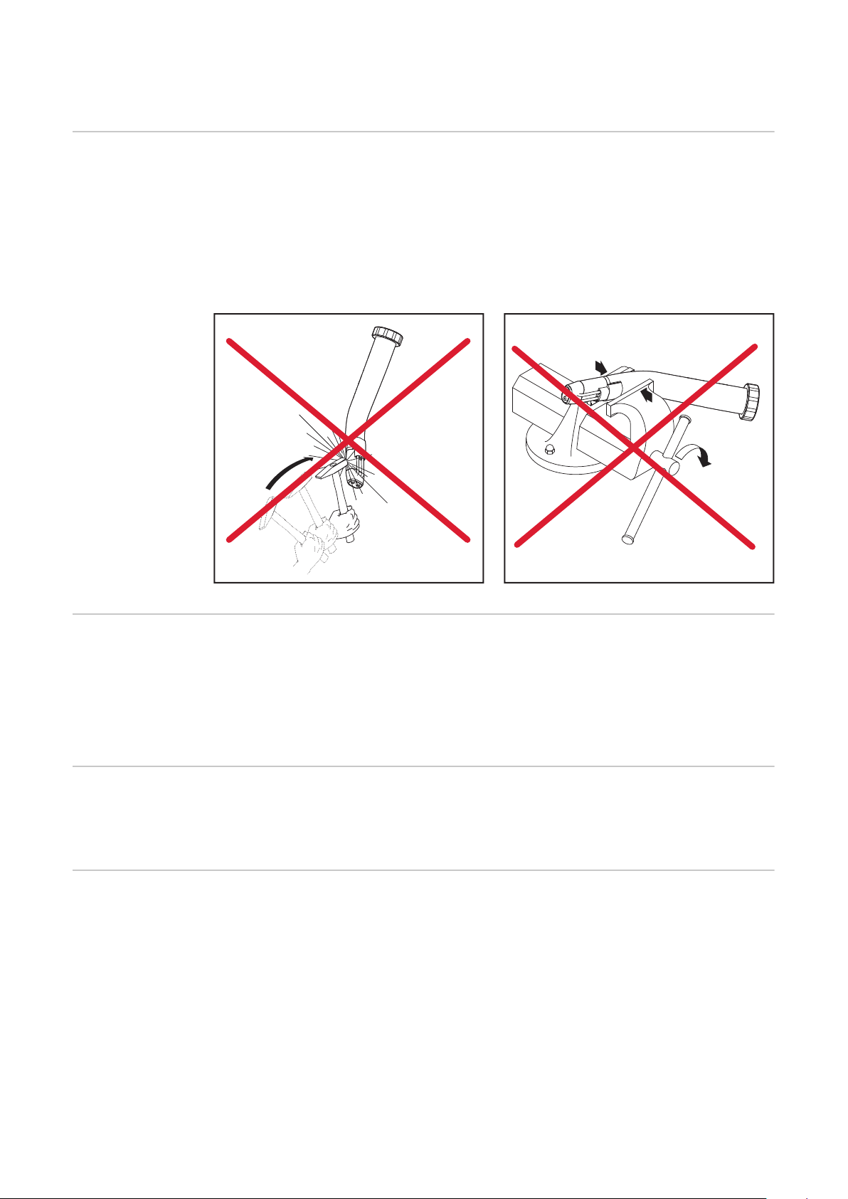
IMPORTANT! When removing welding spatter, avoid making any drag-lines and
scratches. Future welding spatter could get lodged firmly in these.
Do NOT bend the torch neck
-
Every time before starting up
Every time the
wirespool is exchanged
Disposal Waste electrical and electronic equipment must be collected separately and re-
Check the contact tubes
-
If the contact tubes are worn out, exchange them for new ones
-
Clean welding spatter out of the gas nozzle
-
In case of not removable impurities exchange gas nozzle
-
* Check the spatter-guard and all insulation pieces for damage
Recommended: Exchange the inner liner
-
Clean the wirefeed hose with reduced-blow compressed air
-
Clean all wearing parts before fitting them
-
cycled in an environmentally-friendly way, in accordance with the European Directive and national legislation. Used equipment must be returned to the distributor or disposed of via an approved local collection and disposal facility. Correct
disposal of used equipment promotes the sustainable recycling of material resources. Failing to dispose of used equipment correctly can lead to adverse
health and/or environmental impacts.
Packaging materials
Separate collection according to material. Check your local authority regulations.
Crush containers to reduce size.
12
Page 13

Troubleshooting
EN
Troubleshooting
No welding current
Mains switch ON, indicators on the power source are lit up, shielding gas flows
Cause:
Remedy:
Cause:
Remedy:
No protective gas shield
All other functions are OK
Cause:
Remedy:
Cause:
Remedy:
Cause:
Remedy:
Faulty earth (ground) connection
Check the earth (ground) connection and clamp for correct polarity
There is a break in the current cable in the welding torch
Change the torch
The gas cylinder is empty
Change the gas cylinder
The gas pressure regulator is faulty
Replace the gas pressure regulator
The gas hose is not connected, damaged or kinked
Connect/replace the gas hose, or straighten out kinks
Cause:
Remedy:
Cause:
Remedy:
Poor welding properties
Cause:
Remedy:
Cause:
Remedy:
Cause:
Remedy:
Cause:
Remedy:
Cause:
Remedy:
The welding torch is faulty
Replace welding torch
Gas solenoid valve is faulty
Replace gas solenoid valve
Incorrect welding parameters
Check the settings
Poor connection to earth (ground)
Ensure good contact to workpiece
Not enough shielding gas, or none at all
Check the pressure regulator, gas hose, gas solenoid valve and torch
gas connection. On gas cooled welding torches, inspect the gas seals,
use a suitable inner liner.
Welding torch leaking
Exchange the welding torch
Contact tube either too big, or worn out
Change the contact tube
13
Page 14

Poor welding properties
Cause:
Remedy:
Wrong wire alloy and/or wrong wire diameter
Check the wire spool that has been inserted; check the weldability of
the base metal
Cause:
Remedy:
Cause:
Remedy:
Cause:
Remedy:
Cause:
Remedy:
Cause:
Remedy:
Cause:
Remedy:
The shielding gas is not suitable for this wire alloy
Use the correct shielding gas
Unfavourable welding conditions: Shielding gas is contaminated (by
moisture, air), inadequate gas shielding (weld-pool “boiling”,
draughts), contaminants in the workpiece (rust, paint, grease)
Optimise the welding conditions
Welding spatter in the gas nozzle
Remove the welding spatter
Turbulence caused by too high a rate of shielding-gas flow
Reduce the shielding-gas flow-rate. Recommendation:
Shielding-gas flow-rate (l/min) = wire diameter (mm) x 10
(e.g. 16 l/min for a 1.6 mm wire)
Too large a distance between the torch and the workpiece.
Reduce the distance between the torch and the workpiece (recom-
mended: 10-15 mm)
Tilt angle of the welding torch is too large
Reduce the tilt angle of the welding torch
Cause:
Remedy:
Wrong diameter of wirefeed components
Use wirefeed components of the correct diameter
14
Page 15

Poor wirefeed
Cause:
Remedy:
Braking force set too high
Set the brake to a looser setting
EN
Cause:
Remedy:
Cause:
Remedy:
Cause:
Remedy:
Cause:
Remedy:
Cause:
Remedy:
Cause:
Remedy:
Cause:
Remedy:
Hole in contact tube is dislocated
Exchange the contact tube
The wire feed inner liner is defective
Check the wire fee inner liner for kinks, dirt etc.
The wirefeed rollers are not suitable for the wire electrode being used
Use suitable wirefeed rollers
The wirefeed rollers are exerting the wrong contact pressure
Optimise the contact pressure
The wirefeed rollers are soiled or damaged
Clean the wirefeed rollers, or exchange them for new ones
Inner liner dislocated or kinked
Exchange the inner liner
The inner liner or wire inlet nozzle are of the wrong dimension
Ensure that the inner liner or wire inlet nozzle are correctly dimen-
sioned
Cause:
Remedy:
Cause:
Remedy:
Cause:
Remedy:
Cause:
Remedy:
The inner liner was kinked while being inserted
When inserting the inner liner, only touch and hold it near the infeed
tube
After being cut to length, the inner liner is too short
Exchange the inner liner and shorten it to the correct length
The wire is being abraded due to excessive contact pressure on the
wirefeed rollers
Reduce the contact pressure on the wirefeed rollers
Welding wire is dirty / slightly rusty
Use only high-quality wires that are free of contaminants
15
Page 16

The welding torch becomes very hot
Cause:
Remedy:
The swivel nut on the central connector is loose
Tighten the swivel nut
Cause:
Remedy:
Cause:
Remedy:
Cause:
Remedy:
Contact tip has a short service life
Cause:
Remedy:
Cause:
Remedy:
Cause:
Remedy:
The torch has been operated beyond its maximum amperage rating.
Lower the welding power or use a higher-capacity torch
The design dimensions of the torch are not sufficient for this task
Respect the duty cycle and loading limits
Only on water-cooled installations: Coolant through-flow is insufficient
Check the coolant level, through-flow rate, cleanliness of coolant, arrangement of hosepack etc.
Incorrect wirefeeder rollers
Use correct wirefeeder rollers
Wire electrode worn due to excessive contact pressure on the
wirefeeder rollers
Reduce contact pressure on the wirefeeder rollers
Wire electrode contains impurities/is corroded
Use high-quality wire electrode with no impurities
Cause:
Remedy:
Cause:
Remedy:
Cause:
Remedy:
Cause:
Remedy:
NOTE!
When using CrNi, the contact tip may be subject to a higher degree of wear due
to the nature of the surface of the CrNi wire electrode.
Uncoated wire electrode
Use wire electrode with suitable coating
Wrong dimension of contact tip
Use a contact tip of the correct dimension
Duty cycle of welding torch has been exceeded
Shorten the duty cycle or use a more powerful welding torch
Contact tip has overheated. No thermal dissipation as the contact tip
is too loose
Tighten the contact tip
16
Page 17

Weld seam porosity
Cause:
Remedy:
Spatter build-up in the gas nozzle causing inadequate gas-shielding
of the weld seam
Remove welding spatter
EN
Cause:
Remedy:
Cause:
Remedy:
Cause:
Remedy:
Cause:
Remedy:
Cause:
Remedy:
Cause:
Remedy:
Cause:
Remedy:
Either the protective gas shield hose has holes in it, or the hose is not
connected properly
Replace protective gas shield hose
The O-ring seals on the connection points have been cut through or
are faulty
Replace the O-ring seals
Moisture/condensation in the protective gas shield line
Dry protective gas shield line
Protective gas shield flow is either too high or too low
Correct the protective gas shield flow
Insufficient protective gas shield flow rate when welding starts or finishes
Increase gas pre-flow and gas post-flow
Rusty or poor quality wire electrode
Use high-quality wire electrode with no impurities
For gas-cooled welding torches: protective gas is escaping through a
non-insulated inner liner
Use only insulated inner liners with gas-cooled welding torches
Cause:
Remedy:
Too much parting agent applied
Remove excess parting agent/apply less parting agent
17
Page 18

Technical data
Ø
Ø
Ø
Torch necks Explanation of symbols:
water-cooled
X Duty cycle
X / I
40°C)
M21 (EN 439)
X / I
40°C)
C1 (EN 439)
(10 min /
max
(10 min /
max
I
max
(M6) with contact tube M6
(M8) with contact tube M8
Voltage measurement (V-Peak):
for mechanically driven welding torches: 141 V
-
This product conforms to the requirements of IEC 60974-7.
Robacta 160 Robacta 280 Robacta 300 Robacta 400
[%] / [A]
[%] / [A]
[%] / [A]
[%] / [A]
[%] / [A]
[%] / [A]
max. welding current in A
Electrode diameter
-
100 / 160
-
100 / 160
-
100 / 280
-
100 / 280
-
100 / 350
-
100 / 350
-
100 / 250 (M6);
400 (M8)
-
100 / 250 (M6);
400 (M8)
X / I
40°C)
M21 (EN 439)
X / I
40°C)
C1 (EN 439)
(10 min /
max
(10 min /
max
[mm]
[in.]
Robacta 500 Robacta 700 Robacta 700
[%] / [A]
[%] / [A]
[%] / [A]
[%] / [A]
[%] / [A]
[%] / [A]
[mm]
[in.]
0,8 - 1,2
.031 - .047
-
100 / 500
-
100 / 500
0,8 - 1,6
.031 - .063
0,8 - 1,2
.031 -. 047
-
100 / 700
-
100 / 700
1,0 - 1,6
.039 - .063
0,8 - 1,2
.031 - .047
TIME
-
100 / 700
-
100 / 700
1,0 - 1,6
.039 - .063
0,8 - 1,2
.031-.047
Robacta 2500
-
100 / 250
-
100 / 250
0,8 - 1,2
.031-.047
18
Page 19

Ø
Ø
Ø
X / I
(10 min /
max
40°C)
M21 (EN 439)
Robacta 5000 Robacta 7000 Rob. 500-M
(Con-Drive)
[%] / [A]
[%] / [A]
[%] / [A]
-
100 / 500
-
100 / 700
-
100 / 500
Laser HD/W
-
100 / 250
EN
X / I
(10 min /
max
40°C)
C1 (EN 439)
X / I
(10 min /
max
40°C)
M21 (EN 439)
X / I
(10 min /
max
40°C)
M21 (EN 439)
[%] / [A]
[%] / [A]
[%] / [A]
[mm]
[in.]
-
100 / 500
0,8 - 1,6
.031 - .063
Robacta Twin
Single 300
[%] / [A]
[%] / [A]
[%] / [A]
[mm]
[in.]
-
100 / 300
0,8 - 1,6
.031 - .063
Robacta Twin
900 Compact
[%] / [A]
[%] / [A]
[%] / [A]
-
100 / 900
(2x450)
-
100 / 700
1,0 - 1,6
.039 - .063
Robacta Twin
500
-
100 / 500
(2x250)
1,0 - 1,6
.039 - .063
Robacta Twin
Compact
PRO
-
100 / 900
(2x450)
-
100 / 500
0,8 - 1,6
.031 - .063
Robacta Twin
600
-
100 / 600
(2x300)
0,8 - 1,6
.031 - .063
-
100 / 250
1,0 - 1,6
.039 - .063
Robacta Twin
900
-
100 / 900 (2x450)
1,0 - 1,6
.039 - .063
[mm]
[in.]
1,0 - 1,6
.039 - .063
1,0 - 1,6
.039 - .063
19
Page 20

Hosepacks Explanation of symbols:
Ø
Ø
water-cooled
Length of the hosepack
X Duty cycle in %
X / I
(10 min /
max
40°C)
M21 (EN 439)
X / I
(10 min /
max
40°C)
C1 (EN 439)
I
max
max. welding current in A
Electrode diameter
* Lowest cooling power as per IEC 60974-2,
depends on the length of the hosepack
Voltage measurement (V-Peak):
for mechanically driven welding torches: 141 V
-
This product conforms to the requirements of IEC 60974-7.
Robacta Robacta W/CB-PAP
[%] / [A]
[%] / [A]
[%] / [A]
[%] / [A]
[%] / [A]
[%] / [A]
[mm]
[in.]
-
100 / 700
-
100 / 700
0,8 - 1,6
.031 - .063
-
100 / 500
-
100 / 500
0,8 - 1,6
.031 - .063
P
*
min
Q
min
P
min
Q
min
[m] ([W])
[m] ([W])
[m] ([W])
[m] ([W])
[m] ([W])
[m] ([W])
[ft.] ([W])
[ft.] ([W])
[ft.] ([W])
[ft.] ([W])
[ft.] ([W])
[L/min]
[gal./min]1.26 [US]
[bar]
[psi.]
[bar]
[psi.]
1,20 (1100) / 1,50
(1300) / 1,75 (1400) /
2,50 (1400) / 3,50
(1700) / 4,50 (2100) /
3.90 (1100) / 4.90
(1300) /
5.70 (1400) / 8.20
(1400) / 11.4 (1700) /
14.7 (2100)
3
43
5,5
79.74
1,19 (550) / 1,30 (550) / 1,33 (550) /
1,38 (550) / 1,39 (600) / 1,41 (600) /
1,43 (600) / 1,44 (600) / 1,46 (600) /
1,48 (600) / 1,51 (600) / 1,59 (650) /
1,60 (650) / 1,65 (650) / 1,67 (650) /
1,68 (650) / 1,72 (650) / 1,80 (700)
3.90 (550) / 4.20 (550) / 4.30 (550) /
4.50 (550) / 4.50 (600) / 4.60 (600) /
4.70 (600) / 4.80 (600) / 4.90 (600) /
5.20 (650) / 5.20 (650) / 5.40 (650) /
5.50 (650) / 5.60 (650) / 5.90 (700)
1
.26 [US]
3
43
5,5
79.74
20
Page 21

Ø
X / I
40°C)
M21 (EN 439)
(10 min /
max
Robacta Twin Robacta Twin Robacta Twin
Compact/Complete
[%] / [A]
[%] / [A]
[%] / [A]
[mm]
[in.]
-
100 / 900 (2x450)
0,8 - 1,2
.031 - .047
-
100 / 720 (2x360)
0,8 - 1,2
.031 - .047
-
100 / 900 (2x450)
0,8 - 1,6
.031 - .063
EN
P
*
min
[m] ([W])
[m] ([W])
[ft.] ([W])
[ft.] ([W])
Q
min
P
min
Q
min
[L/min]
[gal./min]1.26 [US]
[bar]
[psi.]
[bar]
[psi.]
1,6 (1400) / 2,6
(1900)
5.25 (1400) / 8.53
(1900)
3
43
5,5
79.74
4,5 (2000) 1,6 (1400) / 2,6 (1900) /
3,6 (2400)
14.76 (2000) 5.25 (1400) / 8.53
(1900) / 11.81 (2400)
1
.26 [US]
3
43
5,5
79.74
1
.26 [US]
3
43
5,5
79.74
21
Page 22

22
Page 23

目录
安全 24
安全标识 24
调试 26
设备设计方案 26
安装安装支架(标准) 26
安装安装支架(个性化) 27
安装机器人直颈 28
安装导丝芯 28
连接机器人中继线 30
Robacta Twin Compact Pro – 更换部件 31
维护、保养和废料处理 32
概要 32
每次启动前 32
每次更换焊丝盘时 32
废料处理 32
错误诊断和错误排除 33
错误诊断和错误排除 33
技术数据 38
焊枪体 38
中继线 40
ZH
23
Page 24

安全
安全标识
危险!
误操作和工作不当时存在危险。
此时可能导致严重的人身伤害和财产损失。
仅接受过技术培训且有资质人员方可执行本文档中所述的全部操作和功能。
▶
完整阅读并充分理解本文档。
▶
阅读并理解本设备以及全部系统组件的所有安全规程和用户文档。
▶
危险!
电流存在危险。
此时可能导致严重的人身伤害和财产损失。
在开始工作之前,关闭所有相关的设备和部件,并将它们同电网断开。
▶
保护所有相关设备和部件以使其无法重新开启。
▶
危险!
系统组件故障以及误操作引起的电流存在危险。
此时可能导致严重的人身伤害和财产损失。
所有电缆、引线及中继线必须连接牢固、完好无损且正确绝缘。
▶
仅使用尺寸适当的电缆、引线和中继线。
▶
危险!
冷却剂溢出时存在危险。
此时可能导致严重的人身伤害和财产损失。
当将焊枪与冷却器或其他系统组件断开时,务必使用焊枪附带的塑料密封件密封冷却
▶
剂软管。
危险!
高温系统组件和/或设备存在危险。
此时可能导致严重烧伤或烫伤。
在开始工作前,将所有高温系统组件和/或设备冷却至 +25°C/+77°F(例如冷却剂、水
▶
冷系统组件、送丝机驱动电机等)。
如果无法降温,则必须穿戴合适的保护装置(例如隔热手套、防护眼镜等)。
▶
危险!
接触有毒焊接烟尘时存在危险。
此时可能导致严重的人身伤害。
始终抽取焊接烟尘。
▶
确保足够的新鲜空气供应量。始终确保通风流量至少为每小时 20 m³ (169,070.1 US
▶
gi)。
如有疑问,应请一名安全技术人员对工作场所有毒物质的浓度进行专业评估。
▶
24
Page 25

小心!
无冷却剂操作时存在危险。
此时可能导致财产损失。
切勿在没有冷却剂的情况下操作水冷式焊枪。
▶
在焊接期间,请确保冷却剂正确循环 - 对于伏能士原厂冷却器而言,判断标准为在冷
▶
却器的冷却剂容器中是否可以看到有规律的冷却剂回流。
因不遵守上述规定而造成的任何损失,制造商概不负责。且所有质保索赔均无效。
▶
ZH
25
Page 26
调试
Reibahle /
Reamer /
Alésoir /
Alesatore /
Escariador /
Alar gador
Ø6G7
Bohrer /
Drill /
Foret /
Punta del
trapano /
Broca /
Broca
Ø5,8
设备设计方案 Robacta Twin Compact 机器人中继线体积小重量轻,易于触及焊缝,具有高温稳定性。
可通过一根封闭式的气体管道向机器人的焊枪体导气,从而确保不会出现气体损失。此
外,Robacta Twin Compact 机器人中继线还装配有一根独立的压缩空气管道,用于为机
器人焊枪体排气。
Robacta Twin Compact 机器人焊枪体使用了开创性的连接系统,尺寸极小,能够完美进
入任何狭小空间。该系统采用水冷式气体喷嘴,适用于 MIG/MAG 高性能焊接。
安装安装支架(标
准)
1
3
2
26
重要!为安装支架钻一个 Ø5.8 mm 的孔,再用铰刀将孔扩大,以安装定位销 (Ø6G7)。
重要!必须使用 M8 肩螺钉和 M6 螺钉安装安装支架。用螺钉将安装支架拧入到位后,必
须再打入一个定位销 (Ø6 mm) 将其固定。
Page 27
安装安装支架(个
Reibahle /
Reamer /
Alésoir /
Alesatore /
Escariador /
Alar gador
Ø6G7
Bohrer /
Drill /
Foret /
Punta del
trapano /
Broca /
Broca
Ø5,8
性化)
1
2
ZH
3
重要!为安装支架钻一个 Ø5.8 mm 的孔,再用铰刀将孔扩大,以安装定位销 (Ø6G7)。
重要!必须使用 M8 肩螺钉安装安装支架。放置所需支架并打入两个定位销 (Ø6 mm) 将其
固定。
27
Page 28

安装机器人直颈 重要!弯头和中继线可能受到严重损坏。
*
**
***
1
2
****
2
1
-
在安装过程中,确保灰色接触面不受任何污染。必要时使用干燥的减压压缩空气清洁
接触面。
-
弯头必须拧紧至指定的扭矩。
-
如果接触点损坏,必须更换弯头和中继线。
1
* 定位销
** 接触式触摸感应
*** 连接插头开关盒
***** 规定的扭矩仅适用于可选的扭矩扳手。项目编号见备件清单
2
安装导丝芯
重要!切割导丝芯时,请注意:
-
切割时避免毛刺进入导丝芯
-
将侧刀略微倾斜放置(将毛刺向外拉)
-
磨掉毛刺
小心!
工作不当时存在危险。
此时可能导致严重的财产损失。
必须严格遵守工作步骤顺序和规定的扭矩。
▶
* 可采用扭矩扳手和配套的套筒扳手来代替随附的标准工具。这样可确保将部件以规定的
扭矩拧紧。项目编号见备件清单。
28
Page 29
1
2
1
1
2
3
4
2
3
1
1
1
2
3
*
1
2
4
3
1
2
ZH
3
5
4
6
29
Page 30
连接机器人中继线
1
3
4
5
6
8
9
危险!
电流存在危险。
此时可能导致严重的人身伤害和财产损失。
在开始工作之前,关闭所有相关的设备和部件,并将它们同电网断开。
▶
保护所有相关设备和部件以使其无法重新开启。
▶
危险!
系统组件故障以及误操作引起的电流存在危险。
此时可能导致严重的人身伤害和财产损失。
所有电缆、引线及中继线必须连接牢固、完好无损且正确绝缘。
▶
仅使用尺寸适当的电缆、引线和中继线。
▶
注意!
在使用水冷式焊枪进行焊接作业之前,必须确认系统中有冷却剂!由此造成的任何损失,
伏能士概不负责,且所有保修索赔均无效。
重要!保护气体中混入外来空气会影响焊接效果。
-
如果不使用焊枪吹扫接口,则必须使用随附的塞子将软管末端密封
-
如果压缩空气未连接到用于吹扫功能的电磁阀,请勿连接软管。用塞子密封软管。
1
* 用于可选吹扫焊枪的连接
30
Page 31
Robacta Twin
1
2
3
4
*
Compact Pro – 更
换部件
小心!
小心高温焊枪或冷却剂,避免火灾。
此时可能导致严重烫伤。
只能在焊枪冷却状态下更换、清洁和检查部件。
▶
小心!
误操作及工作不当时存在危险。
此时可能导致严重的财产损失。
必须严格遵守工作步骤顺序和规定的扭矩。
▶
* 可采用扭矩扳手和配套的套筒扳手来代替随附的标准工具。这样可确保将部件以规
定的扭矩拧紧。项目编号见备件清单。
1 2
ZH
3 4
31
Page 32

维护、保养和废料处理
概要 要确保无故障操作,定期对焊枪进行预防性维护至关重要。焊枪容易受到高温和重污的影
响。因此,与焊接系统的其他部件相比,焊枪需要更频繁的维护。
重要!清除焊接飞溅物时,避免产生拖线和划痕。否则,后来产生的焊接飞溅物将牢固地
附着其上。
-
请勿弯曲焊枪体
每次启动前
每次更换焊丝盘时
废料处理 废弃的电气和电子设备必须单独收集,并按照欧洲指令和国家相关法律法规以无害于环境
-
检查导电嘴
-
如果导电嘴出现磨损,请更换
-
清除气体喷嘴中的焊接飞溅物
-
如杂质无法清除,请更换气体喷嘴
* 检查防溅罩和所有绝缘件是否损坏
-
建议:更换导丝管
-
用减压压缩空气吹扫送丝管
-
所有易损件均应在清洗后再进行安装
的方式回收。使用过的设备必须归还经销商或通过当地批准的收集和处理设施进行处置。
正确处置使用过的设备可促进材料资源的可持续循环利用。未能正确处置使用过的设备可
能会对健康和/或环境造成不利影响。
包装材料
需根据材料分类收集,并检查当地政府的规章制度,同时,挤压容器以缩小体积。
32
Page 33

错误诊断和错误排除
错误诊断和错误排
除
无焊接电流
主开关处于“打开”状态,电源上的指示灯点亮,保护气体流动
原因:
解决方法:
原因:
解决方法:
无保护气体
所有其他功能可用
原因:
措施:
原因:
措施:
原因:
措施:
接地连接错误
检查接地连接并检查固定卡夹的极性
焊枪中的载流电缆损坏
更换焊枪
气瓶空了
更换气瓶
保护气流量计损坏
更换保护气流量计
气管未安装或受损,弯折
安装、拉直或更换气管
ZH
原因:
措施:
原因:
措施:
焊接特性差
原因:
解决方法:
原因:
解决方法:
原因:
解决方法:
原因:
解决方法:
原因:
解决方法:
焊枪损坏
更换焊枪
气体磁阀损坏
更换气体磁阀
焊接参数错误
检查设置
接地连接不良
确保与工件良好接触
保护气体不足或根本没有
检查压力调节器、气管、气路电磁阀和焊枪气体接口。检查气冷式焊枪的气
密性,使用合适的导丝管。
焊枪泄漏
更换焊枪
导电嘴太大或磨损
更换导电嘴
33
Page 34

焊接特性差
原因:
解决方法:
焊丝合金及/或直径错误
检查是否已插入焊丝盘;检查母材的可焊性
原因:
解决方法:
原因:
解决方法:
原因:
解决方法:
原因:
解决方法:
原因:
解决方法:
原因:
解决方法:
原因:
解决方法:
保护气体不适用于目前的电极丝合金
使用适当的保护气体
不适宜的焊接条件:保护气体受污染(由潮气、空气造成),气体保护不充
足(熔池“沸腾”,气流),工件污染(锈蚀、涂料、油脂)
优化焊接条件
气体喷嘴处有焊接飞溅物
清除焊接飞溅物
由于保护气体流速过高而导致紊流
降低保护气体流速。建议:
保护气体流速 (l/min) = 焊丝直径 (mm) x 10
(例如,对于 1.6 mm 的焊丝采用 16 l/min 的流速)
焊枪和工件之间的距离过大。
缩短焊枪和工件之间的距离(建议:10–15 mm)
焊枪倾角过大
减小焊枪倾角
送丝部件直径错误
使用正确直径的送丝部件
34
Page 35

送丝不良
原因:
解决方法:
制动力设置过高
将制动器设置略微调松
原因:
解决方法:
原因:
解决方法:
原因:
解决方法:
原因:
解决方法:
原因:
解决方法:
原因:
解决方法:
原因:
解决方法:
导电嘴孔错位
更换导电嘴
送丝导丝管有缺陷
检查送丝导丝管是否扭结、有灰尘等
送丝轮与正在使用的焊丝不匹配
使用合适的送丝轮
送丝轮压紧力错误
优化接触压紧力
送丝轮脏污或损坏
清洁送丝轮或更换新的送丝轮
导丝管布设错误或打结
更换导丝管
导丝管或焊丝入口喷嘴尺寸错误
确保导丝管或焊丝入口喷嘴尺寸正确
ZH
原因:
解决方法:
原因:
解决方法:
原因:
解决方法:
原因:
解决方法:
焊枪变得很热
原因:
解决方法:
原因:
解决方法:
原因:
解决方法:
导丝管插入时打结
插入导丝管时,仅触摸并握住焊丝导入管部分
导丝管剪切后长度太短
更换导丝管并将其剪切到正确的长度
由于送丝轮上的压紧力过大,焊丝受到磨损
减小送丝轮上的压紧力
焊丝脏污/轻度锈蚀
仅使用无污染的优质焊丝
中央接口上的旋转螺母松动
拧紧旋转螺母
使用焊枪时超出最大额定电流强度。
降低焊接功率或使用更高电容的焊枪
焊枪的设计尺寸不能胜任这样的任务
遵守暂载率和负载的限制要求
原因:
解决方法:
只在水冷式机器上:冷却剂贯流量不足
检查冷却剂液位、贯流量、冷却剂的清洁度、中继线的布置等。
35
Page 36

导电嘴使用寿命过短
原因:
解决方法:
送丝轮不正确
使用正确的送丝轮
原因:
解决方法:
原因:
解决方法:
原因:
解决方法:
原因:
解决方法:
原因:
解决方法:
原因:
解决方法:
由于送丝轮上的压紧力过大而导致焊丝磨损
减小送丝轮上的压紧力
焊丝含有杂质或被腐蚀
使用无杂质的优质焊丝
无涂层焊丝
使用带有合适涂层的焊丝
导电嘴尺寸不合适
使用合适尺寸的导电嘴
焊枪暂载率过长
缩短暂载率或使用更高功率的焊枪
导电嘴过热。由于导电嘴过松而导致无法散热
紧固导电嘴
注意!
使用 CrNi 时,由于 CrNi 焊丝自身的特性,导电嘴可能需要承受更高程度的磨损。
36
Page 37

焊缝存在多孔
原因:
措施:
瓦嘴内积聚飞溅物导致焊缝保护气体不足
清除焊接飞溅物
原因:
措施:
原因:
措施:
原因:
措施:
原因:
措施:
原因:
措施:
原因:
措施:
原因:
措施:
保护气体软管内有孔或保护气体软管连接错误
更换保护气体软管
接口上的 O 形圈被切断或损坏
更换 O 形圈
保护气体管内有湿气/冷凝水
对保护气体管进行干燥处理
保护气体流量过大或过小
修正保护气体流量
焊接开始或焊接结束时保护气体流量不足
延长提前送气时间和滞后停气时间
焊丝生锈或焊丝质量差
使用未被污染的高品质焊丝
适用于气冷式焊枪:使用非绝缘送丝管时保护气体流出
采用气冷式焊枪时只能使用绝缘送丝管
ZH
原因:
措施:
分离剂涂抹过多
清除多余的分离剂/涂较少的分离剂
37
Page 38

技术数据
Ø
Ø
Ø
焊枪体 符号说明:
X 暂载率
水冷
X / I
40°C)
M21 (EN 439)
X / I
40°C)
C1 (EN 439)
最大值
最大值
(10 min /
(10 min /
I
最大值
(M6) 带 M6 导电嘴
(M8) 带 M8 导电嘴
电压测量(V 峰值):
-
针对机械驱动焊枪:141 V
产品符合 IEC 60974-7 标准的相关要求。
Robacta 160 Robacta 280 Robacta 300 Robacta 400
[%] / [A]
[%] / [A]
[%] / [A]
[%] / [A]
[%] / [A]
[%] / [A]
最大焊接电流 (A)
电极直径
-
100 / 160
-
100 / 160
-
100 / 280
-
100 / 280
-
100 / 350
-
100 / 350
-
100 / 250 (M6);400
(M8)
-
100 / 250 (M6);400
(M8)
X / I
40°C)
M21 (EN 439)
X / I
40°C)
C1 (EN 439)
最大值
最大值
(10 min /
(10 min /
[mm]
[in.]
Robacta 500 Robacta 700 Robacta 700
[%] / [A]
[%] / [A]
[%] / [A]
[%] / [A]
[%] / [A]
[%] / [A]
[mm]
[in.]
0.8 – 1.2
0.031 – 0.047
-
100 / 500
-
100 / 500
0.8 – 1.6
0.031 – 0.063
0.8 – 1.2
0.031 –0.047
-
100 / 700
-
100 / 700
1.0 – 1.6
0.039 – 0.063
0.8 – 1.2
0.031 – 0.047
TIME
-
100 / 700
-
100 / 700
1.0 – 1.6
0.039 – 0.063
0.8 – 1.2
0.031 – 0.047
Robacta 2500
-
100 / 250
-
100 / 250
0.8 – 1.2
0.031 – 0.047
38
Page 39

Ø
Ø
Ø
X / I
最大值
(10 min /
40°C)
M21 (EN 439)
Robacta 5000 Robacta 7000 Rob. 500-M
(Con-Drive)
[%] / [A]
[%] / [A]
[%] / [A]
-
100 / 500
-
100 / 700
-
100 / 500
Laser HD/W
-
100 / 250
X / I
最大值
(10 min /
40°C)
C1 (EN 439)
X / I
最大值
(10 min /
40°C)
M21 (EN 439)
X / I
最大值
(10 min /
40°C)
M21 (EN 439)
[%] / [A]
[%] / [A]
[%] / [A]
[mm]
[in.]
-
100 / 500
0.8 – 1.6
0.031 – 0.063
Robacta Twin
Single 300
[%] / [A]
[%] / [A]
[%] / [A]
[mm]
[in.]
-
100 / 300
0.8 – 1.6
0.031 – 0.063
Robacta Twin
900 Compact
[%] / [A]
[%] / [A]
[%] / [A]
-
100 / 900
(2x450)
-
100 / 700
1.0 – 1.6
0.039 – 0.063
Robacta Twin
500
-
100 / 500
(2x250)
1.0 – 1.6
0.039 – 0.063
Robacta Twin
Compact PRO
-
100 / 900
(2x450)
-
100 / 500
0.8 – 1.6
0.031 – 0.063
Robacta Twin
600
-
100 / 600
(2x300)
0.8 – 1.6
0.031 – 0.063
-
100 / 250
1.0 – 1.6
0.039 – 0.063
Robacta Twin
900
-
100 / 900 (2x450)
1.0 – 1.6
0.039 – 0.063
ZH
[mm]
[in.]
1.0 – 1.6
0.039 – 0.063
1.0 – 1.6
0.039 – 0.063
39
Page 40

中继线 符号说明:
Ø
Ø
X 暂载率 (%)
水冷
中继线的长度
X / I
最大值
(10 min /
40°C)
M21 (EN 439)
X / I
最大值
(10 min /
40°C)
C1 (EN 439)
I
最大值
最大焊接电流 (A)
电极直径
* 最低冷却功率符合 IEC 60974-2 标准,
具体取决于中继线长度
电压测量(V 峰值):
-
针对机械驱动焊枪:141 V
产品符合 IEC 60974-7 标准的相关要求。
Robacta Robacta W/CB-PAP
[%] / [A]
[%] / [A]
[%] / [A]
[%] / [A]
[%] / [A]
[%] / [A]
[mm]
[in.]
-
100 / 700
-
100 / 700
0.8 – 1.6
0.031 – 0.063
-
100 / 500
-
100 / 500
0.8 – 1.6
0.031 – 0.063
P
Q
P
Q
最小值
最小值
最小值
最小值
[m] ([W])
*
1.20 (1100) / 1.50 (1300) /
[m] ([W])
[m] ([W])
1.75 (1400) / 2.50 (1400) /
3.50 (1700) / 4.50 (2100) /
[m] ([W])
[m] ([W])
[m] ([W])
[ft.] ([W])
[ft.] ([W])
[ft.] ([W])
3.90 (1100) / 4.90 (1300) /
5.70 (1400) / 8.20 (1400) /
11.4 (1700) / 14.7 (2100)
[ft.] ([W])
[ft.] ([W])
[L/min]
[gal./min]1.26 [US]
[bar]
[psi.]
[bar]
[psi.]
3
43
5.5
79.74
1.19 (550) / 1.30 (550) / 1.33 (550) / 1.38
(550) / 1.39 (600) / 1.41 (600) / 1.43
(600) / 1.44 (600) / 1.46 (600) / 1.48
(600) / 1.51 (600) / 1.59 (650) / 1.60
(650) / 1.65 (650) / 1.67 (650) / 1.68
(650) / 1.72 (650) / 1.80 (700)
3.90 (550) / 4.20 (550) / 4.30 (550) / 4.50
(550) / 4.50 (600) / 4.60 (600) / 4.70
(600) / 4.80 (600) / 4.90 (600) / 5.20
(650) / 5.20 (650) / 5.40 (650) / 5.50
(650) / 5.60 (650) / 5.90 (700)
1
.26 [US]
3
43
5.5
79.74
40
Page 41

Ø
X / I
40°C)
最大值
(10 min /
M21 (EN 439)
P
Q
最小值
最小值
*
P
最小值
Q
最小值
Robacta Twin Robacta Twin Robacta Twin
[%] / [A]
[%] / [A]
[%] / [A]
[mm]
[in.]
[m] ([W])
[m] ([W])
[ft.] ([W])
[ft.] ([W])
[L/min]
[gal./min]1.26 [US]
[bar]
[psi.]
[bar]
[psi.]
Compact/Complete
-
100 / 900 (2x450)
0.8 – 1.2
0.031 – 0.047
-
100 / 720 (2x360)
0.8 – 1.2
0.031 – 0.047
-
100 / 900 (2x450)
0.8 – 1.6
0.031 – 0.063
1.6 (1400) / 2.6 (1900) 4.5 (2000) 1.6 (1400) / 2.6 (1900) /
3.6 (2400)
5.25 (1400) / 8.53
(1900)
3
43
5.5
79.74
14.76 (2000) 5.25 (1400) / 8.53 (1900) /
11.81 (2400)
1
.26 [US]
3
43
5.5
79.74
1
.26 [US]
3
43
5.5
79.74
ZH
41
Page 42

42
Page 43

ZH
43
Page 44

Fronius International GmbH
Froniusstraße 1
4643 Pettenbach
Austria
contact@fronius.com
www.fronius.com
Under www.fronius.com/contact you will find the adresses
of all Fronius Sales & Service Partners and locations.
spareparts.fronius.com
SPAREPARTS
ONLINE
 Loading...