

Page 1

Operating
Instructions
Robacta TTW 4500
Robacta TTW 5500
Bedienungsanleitung
DE
Operating Instructions
EN
Instructions de service
FR
Instrukcja obsługi
PL
42,0410,1341 008-13052022
Page 2

Page 3

Inhaltsverzeichnis
Allgemeines 4
Gerätekonzept 4
Einsatzgebiete 4
Lieferumfang und Optionen 5
Haltewinkel montieren (Standard) 6
Sicherheit 6
Haltewinkel montieren (Standard) 6
Haltewinkel montieren (Individuell) 7
Sicherheit 7
Haltewinkel montieren (Individuell) 7
Robacta TTW 4500 zusammenbauen 8
Sicherheit 8
Robacta TTW 4500 zusammenbauen 8
Option Engspalt-Gasdüse montieren 8
Wolframelektrode einstellen 10
Sicherheit 10
Wolframelektrode einstellen 10
Inbetriebnahme 11
Sicherheit 11
Bestimmungsgemäße Verwendung 11
Inbetriebnahme 11
Fehlerdiagnose, Fehlerbehebung 12
Sicherheit 12
Fehlerdiagnose, Fehlerbehebung 12
Pflege, Wartung und Entsorgung 13
Allgemeines 13
Bei jeder Inbetriebnahme 13
Monatlich 13
Entsorgung 13
Technische Daten 14
TTW 4500 14
TTW 5500 14
DE
3
Page 4

Allgemeines
(6) (1)(5)
(2)(3)
(4)
Gerätekonzept Der wassergekühlte Roboter-Schweißbrenner Robacta TTW 4500 dient zum au-
tomatisierten WIG-Schweißen und Wig-Löten.
Der Robacta TTW 4500 ist serienmäßig mit einem Fronius F++ Anschluss ausgestattet.
Robacta TTW 4500 mit erhältlichen Optionen
(1) Schlauchpaket Robacta TTW 4500
(2) Option Robacta KD Drive / KD Drive
(3) Option Heißdraht
(4) Option Zündhilfe
(5) Option Schleppgasdüse
(6) Anschluss für Kollisionsbox
Einsatzgebiete Der Roboter-Schweißbrenner Robacta TTW 4500 kommt bei automatisierten
Anwendungen zum Einsatz, z.B.:
im Rohrleitungs- und Apparatebau
-
im Behälterbau
-
in der Automobilindustrie
-
bei höchsten Qualitätsanforderungen
-
zum Verschweißen von Materialien mit einer Blechdicke von 0,6 - 10 mm
-
4
Page 5
Lieferumfang
*
(1)
(5)
(2)
(3)
(4)
(6)
(9)
(8)
(7)
und Optionen
DE
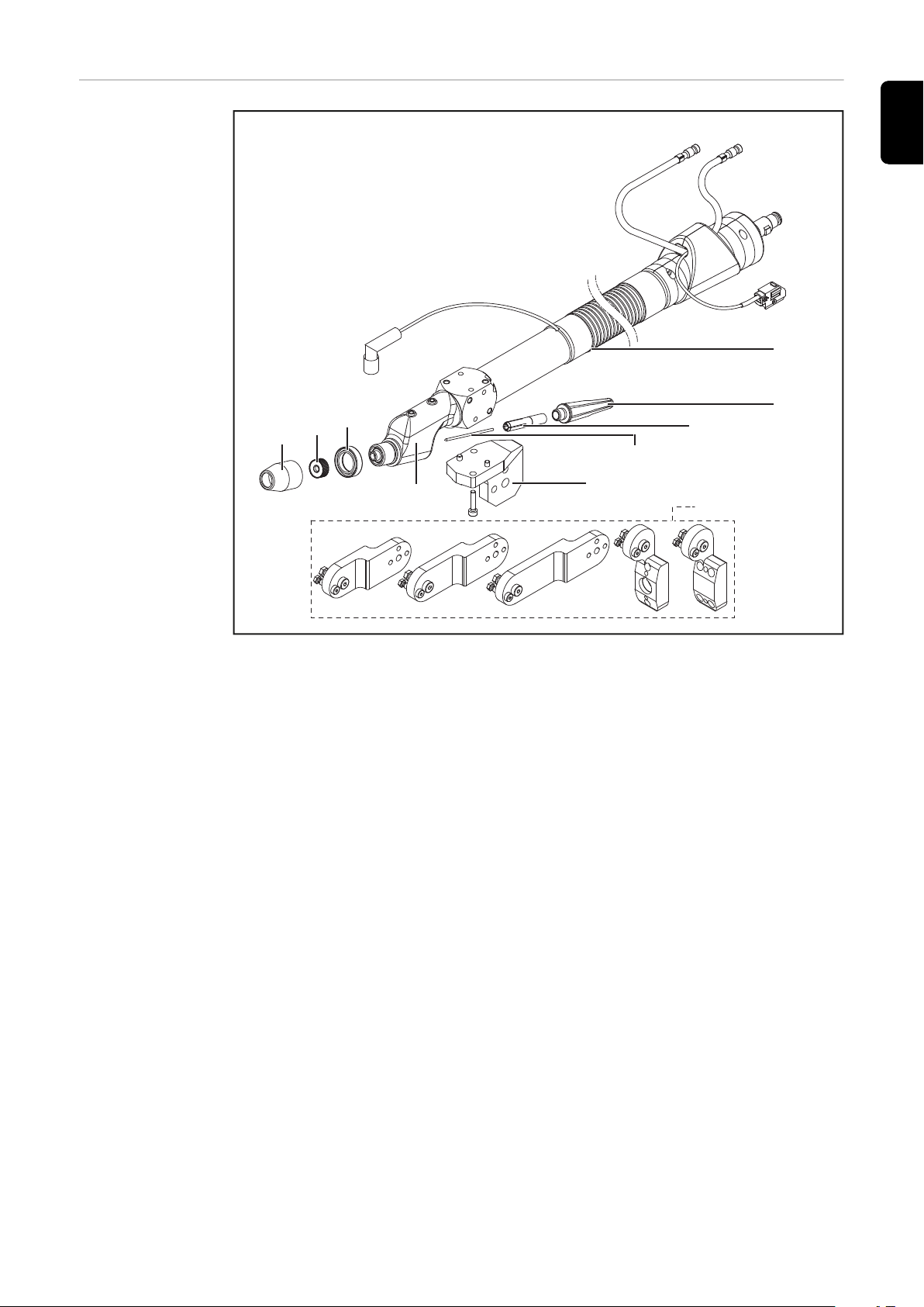
Lieferumfang Robacta TTW 4500
(1) Schlauchpaket 6 m (19.7 ft.) / 8 m (26 ft.), Fronius F++ Anschluss
(2) Schweißbrenner-Kappe TTW 4500
(3) Spannhülse D = 3,2 mm (1/8 in.)
(4) Wolfram Elektrode WL 20 D = 3,2 mm (1/8 in.)
(5) Schweißbrenner-Halterung
(6) Schweißbrenner-Körper
(7) Anschlagring
(8) Gaslinse
(9) Schutzgas-Düse
Folgende Optionen sind für den Roboter-Schweißbrenner Robacta TTW 4500
verfügbar:
* Verlängerung für Schweißbrenner-Halterung am Roboter
Ohne Abbildung:
Kaltdraht-Zuführung mit Antrieb (Push-Pull-System): Robacta Plasma KD
-
Drive
Kaltdraht-Zuführung (Push-System): Robacta Plasma KD
-
Option Heißdraht
-
Option Gaslinse für Gasdüsen 3/4 in.
-
Option Zündhilfe
-
Spannhülse 1,6 / 2,4 / 4,0 / 4,8 mm (1/16, 3/32, 5/32, 3/16)
-
Adapter für Fronius Z Zentralanschluss
-
5
Page 6

Haltewinkel montieren (Standard)
Reibahle
Ø6G7
Bohrer
Ø5,8
1
2
Sicherheit
Haltewinkel
montieren (Standard)
WARNUNG!
Gefahr durch Fehlbedienung und fehlerhaft durchgeführte Arbeiten.
Schwere Personen- und Sachschäden können die Folge sein.
Alle in diesem Dokument beschriebenen Arbeiten und Funktionen dürfen
▶
nur von technisch geschultem Fachpersonal ausgeführt werden.
Dieses Dokument vollständig lesen und verstehen.
▶
Sämtliche Sicherheitsvorschriften und Benutzerdokumentationen dieses
▶
Gerätes und aller Systemkomponenten lesen und verstehen.
WICHTIG!
Zum Fixieren der eingerichteten Stellung verbohren Sie die Halter mit Ø5,8
-
mm und reiben mittels einer Reibahle die Bohrung für den Pass-Stift Ø6G7
auf.
Der Haltewinkel muss mit einer Pass-Schulter-Schraube M8 und mit einer
-
Schraube M6 montiert werden.
Nach dem Verschrauben muss noch ein Pass-Stift (Ø6 mm) zur Sicherung
eingepresst werden.
1
2
6
3
Page 7

Haltewinkel montieren (Individuell)
Reibahle
Ø6G7
Bohrer
Ø5,8
1
6
1
2
DE
Sicherheit
Haltewinkel
montieren (Individuell)
WARNUNG!
Gefahr durch Fehlbedienung und fehlerhaft durchgeführte Arbeiten.
Schwere Personen- und Sachschäden können die Folge sein.
Alle in diesem Dokument beschriebenen Arbeiten und Funktionen dürfen
▶
nur von technisch geschultem Fachpersonal ausgeführt werden.
Dieses Dokument vollständig lesen und verstehen.
▶
Sämtliche Sicherheitsvorschriften und Benutzerdokumentationen dieses
▶
Gerätes und aller Systemkomponenten lesen und verstehen.
WICHTIG!
Zum Fixieren der eingerichteten Stellung verbohren Sie die Halter mit Ø5,8
-
mm und reiben mittels einer Reibahle die Bohrung für den Pass-Stift Ø6G7
auf.
Der Haltewinkel muss mit einer Pass-Schulter-Schraube M8 montiert wer-
-
den.Danach muss der gewünschte Winkel eingestellt und zwei Pass-Stifte
(Ø6 mm) zur Sicherung eingepresst werden.
1
2
3
7
Page 8
Robacta TTW 4500 zusammenbauen
1
3
2
4
1
4
3
2
5
Sicherheit
Robacta TTW
4500 zusammenbauen
WARNUNG!
Gefahr durch Fehlbedienung und fehlerhaft durchgeführte Arbeiten.
Schwere Personen- und Sachschäden können die Folge sein.
Alle in diesem Dokument beschriebenen Arbeiten und Funktionen dürfen
▶
nur von technisch geschultem Fachpersonal ausgeführt werden.
Dieses Dokument vollständig lesen und verstehen.
▶
Sämtliche Sicherheitsvorschriften und Benutzerdokumentationen dieses
▶
Gerätes und aller Systemkomponenten lesen und verstehen.
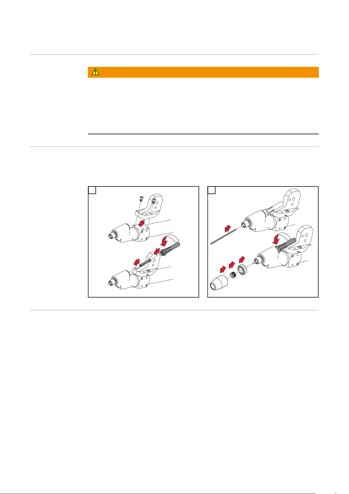
WICHTIG! Die Wolframelektrode so einsetzen, dass die Spitze ca. 10 mm (.4 in.)
aus dem Brennerkörper ragt. Brennerkappe nur leicht anziehen, damit die Wolframelektrode im Brennerkörper noch verschiebbar ist.
1
2
Option EngspaltGasdüse montieren
8
Für die Montage der Engspalt-Gasdüse sind folgende Artikel zusätzlich erforderlich:
Isolierring D 35,5 mm - 42,0100,0010
-
Gasmantelring M18 x 1,5 mm - 42,0001,6781
-
Engspalt-Gasdüse - 42,0300,3210
-
Page 9

1
2
3
4
5
5
1
1
*
2
*
2
1
3
~ 15 mm
1
**
1
2
2
DE
* Bis auf Anschlag aufschrauben
3
4
** Bis auf Anschlag montieren
5
9
Page 10
Wolframelektrode einstellen
1
3
2
(0 in.)
0 mm
2
1
3
2
3
1
Sicherheit
Wolframelektrode einstellen
WARNUNG!
Gefahr durch Fehlbedienung und fehlerhaft durchgeführte Arbeiten.
Schwere Personen- und Sachschäden können die Folge sein.
Alle in diesem Dokument beschriebenen Arbeiten und Funktionen dürfen
▶
nur von technisch geschultem Fachpersonal ausgeführt werden.
Dieses Dokument vollständig lesen und verstehen.
▶
Sämtliche Sicherheitsvorschriften und Benutzerdokumentationen dieses
▶
Gerätes und aller Systemkomponenten lesen und verstehen.
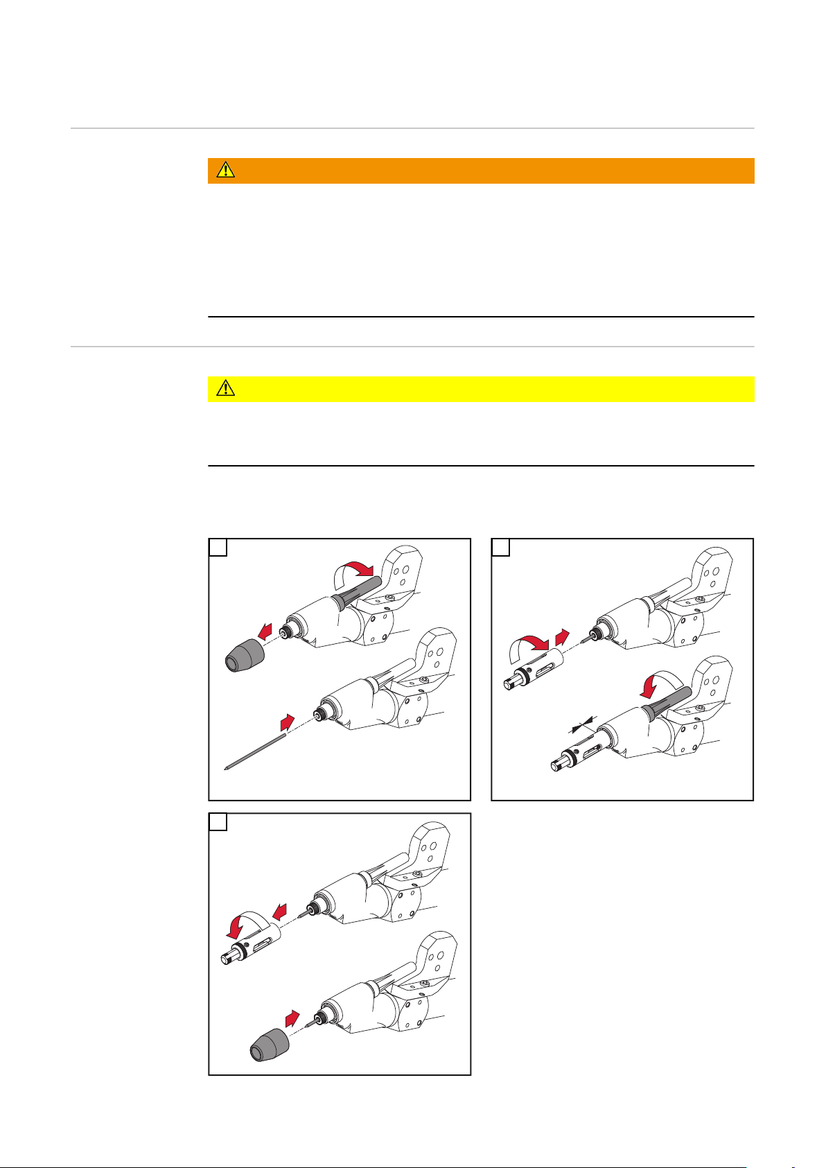
VORSICHT!
Eine falsch eingestellte Wolframelektrode kann die Gasdüse beschädigen.
Wolframelektrode entsprechend der Gasdüse und gemäß der jeweiligen An-
▶
wendung einstellen.
WICHTIG! Beim Einstellen der Wolframelektrode Schweißbrenner in senkrechte
Position bringen.
1
2
3
10
Page 11

Inbetriebnahme
(1)
(3)
(2)
(4)
DE
Sicherheit
Bestimmungsgemäße Verwendung
Inbetriebnahme
WARNUNG!
Fehlbedienung kann schwerwiegende Personen- und Sachschäden verursachen.
Beschriebene Funktionen erst anwenden, wenn folgende Dokumente vollständig
gelesen und verstanden wurden:
diese Bedienungsanleitung
▶
sämtliche Bedienungsanleitungen der Systemkomponenten, insbesondere
▶
Sicherheitsvorschriften
Die WIG Roboter-Schweißbrenner ist ausschließlich zum WIG-Schweißen und
WIG-Löten bestimmt.
Eine andere oder darüber hinausgehende Benutzung gilt als nicht bestimmungsgemäß. Für hieraus entstehende Schäden haftet der Hersteller nicht.
Zur bestimmungsgemäßen Verwendung gehört auch
das Beachten aller Hinweise aus der Bedienungsanleitung
-
die Einhaltung der Inspektions- und Wartungsarbeiten
-
Schweißbrenner am Roboter aufbauen
1
Schweißbrenner auf Vollständigkeit und richtiger Montage kontrollieren
2
VORSICHT!
Eine Eine falsch eingestellte Wolframelektrode kann die Gasdüse beschädigen!
Wolframelektrode entsprechend der Gasdüse und gemäß der jeweiligen An-
▶
wendung einstellen!
Einstellung Wolframelektrode kontrollieren
3
Schlauchpaket anschließen
4
(1) Strom / Schutzgas
(2) Wasserrücklauf
(3) Wasservorlauf
(4) Kabel für Kollisionsbox
Bei Erstinbetriebnahme auf korrek-
5
te Gasströmung achten
Schweißbrenner positionieren (Ro-
6
boter einrichten)
Schutzgas für mindestens 30 s
7
spülen
Der Schweißbrenner ist einsatzbe-
8
reit
Anschlüsse Schweißbrenner
11
Page 12

Fehlerdiagnose, Fehlerbehebung
Sicherheit
Fehlerdiagnose,
Fehlerbehebung
WARNUNG!
Gefahr durch elektrischen Strom.
Schwere Personen- und Sachschäden können die Folge sein.
Vor Beginn der Arbeiten alle beteiligten Geräte und Komponenten ausschal-
▶
ten und von Stromnetz trennen.
Alle beteiligten Geräte und Komponenten gegen Wiedereinschalten sichern.
▶
Nach dem Öffnen des Gerätes mit Hilfe eines geeigneten Messgerätes si-
▶
cherstellen, dass elektrisch geladene Bauteile (beispielsweise Kondensatoren) entladen sind.
Lichtbogen zündet nicht
Ursache:
Behebung:
Ursache:
Behebung:
Schutzgas-Abdeckung nicht ausreichend
Ursache:
Behebung:
Wolframelektrode verschmutzt
Wolframelektrode reinigen
Wolframelektrode falsch positioniert
Wolframelektrode richtig positionieren
Gaslinse im Schweißbrenner fehlt
Gaslinse montieren
12
Page 13
Pflege, Wartung und Entsorgung
Allgemeines Regelmäßige und vorbeugende Wartung des Schweißbrenners sind wesentliche
Faktoren für einen störungsfreien Betrieb. Der Schweißbrenner ist hohen Temperaturen ausgesetzt. Daher benötigt der Schweißbrenner eine häufigere Wartung
als andere Komponenten einer Schweißanlage.
WARNUNG!
Ein elektrischer Schlag kann tödlich sein.
Vor Arbeiten am Schweißbrenner:
Netzschalter von Stromquelle in Stellung - O - schalten
▶
Stromquelle vom Netz trennen
▶
ein verständliches Warnschild gegen Wiedereinschalten anbringen
▶
DE
Bei jeder Inbetriebnahme
Monatlich
Entsorgung Die Entsorgung nur gemäß den geltenden nationalen und regionalen Bestimmun-
Schweißbrenner, Schlauchpaket und Stromanschlüsse auf Beschädigung
-
prüfen
Gas- und Wasseranschlüsse auf Dichtheit prüfen
-
Kühlgerät auf einwandfreie Funktion überprüfen, Wasser Rückflussmenge im
-
Kühlmittelbehälter überwachen und gegebenenfalls Kühlgerät entlüften
Verschleißteile auf einwandfreien Zustand prüfen, Verschleißteile vor dem
-
Einbau reinigen
Falls vorhanden, Filter im Kühlkreislauf auf Verunreinigung prüfen
-
Kühlmittel auf Reinheit prüfen. Bei Verunreinigung das Kühlmittel austau-
-
schen und Schweißbrenner über Kühlmittel-Vorlauf und Kühlmittel-Rücklauf
mehrmals durchspülen
HINWEIS!
Ablagerungen im Inneren des Schweißbrenners können Hochfrequenz-Überschläge verursachen und somit den Schweißbrenner beschädigen
Schweißbrenner zerlegen und auf Ablagerungen / Verunreinigungen prüfen
-
gen durchführen.
13
Page 14

Technische Daten
TTW 4500
Technische Daten nach IEC 60974-7
Spannungsbemessung (V-Peak)* 141 V
Zündspannung (Up) 10 kV
Schutzgas Argon EN 439
Kühlsystem Flüssigkeitskühlung
Kühlmittel Original Fronius Kühlmittel
Kühlmitteldruck min. / max. 3,0 / 5,5 bar
43,50 / 79,74 psi
Kühlmittel-Mindestdurchfluss 1,0 l/min
1.06 qt/min
Schweißstrom DC bei 10 min / 40°C (104°F)
Schweißstrom AC bei 10 min / 40°C (104°F)
100 % ED
60 % ED
100 % ED
60 % ED
1)
1)
1)
1)
350 A
450 A
250 A
320 A
Schlauchpaket-Länge 1,35 m / 6 m / 8 m
4,4 ft / 19,7 ft, / 26 ft
Mindest Kühlleistung Kühlgerät lt. IEC 60974 - 2 450 W / 850 W / 1000 W
TTW 5500
Elektroden-Durchmesser 1,6 - 4,8 mm
1/16 - 3/16 in.
*) Für maschinell geführte Schweißbrenner
1) ED = Einschaltdauer
Technische Daten nach IEC 60974-7
Spannungsbemessung (V-Peak)* 141 V
Zündspannung (Up) 10 kV
Schutzgas Argon EN 439
Kühlsystem Flüssigkeitskühlung
Kühlmittel Original Fronius Kühlmittel
Kühlmitteldruck min. / max. 3,0 / 5,5 bar
43,50 / 79,74 psi
Kühlmittel-Mindestdurchfluss 1,0 l/min
1.06 qt/min
Schweißstrom DC bei 10 min / 40°C (104°F)
Schweißstrom AC bei 10 min / 40°C (104°F)
100 % ED
60 % ED
100 % ED
60 % ED
1)
1)
1)
1)
430 A
550 A
300 A
400 A
14
Page 15

Schlauchpaket-Länge 6 m / 8 m
19,7 ft, / 26 ft
Mindest Kühlleistung Kühlgerät lt. IEC 60974 - 2 1100 W / 1400 W
DE
Elektroden-Durchmesser
*) Für maschinell geführte Schweißbrenner
1) ED = Einschaltdauer
3,2 - 6,4 mm
1/8 - 1/4 in.
15
Page 16

16
Page 17

Contents
General 18
Device concept 18
Application areas 18
Scope of supply and options 19
Fitting the mounting bracket (standard) 20
Safety 20
Fitting the mounting bracket (standard) 20
Fitting the mounting bracket (individually) 21
Safety 21
Fitting the mounting bracket (individually) 21
Assembling the Robacta TTW 4500 22
Safety 22
Assembling the Robacta TTW 4500 22
Fitting the narrow-gap gas nozzle (option) 22
Adjusting the tungsten electrode 24
Safety 24
Adjusting the tungsten electrode 24
Start-up 25
Safety 25
Utilisation in accordance with „intended purpose“ 25
Commissioning 25
Troubleshooting 26
Safety 26
Troubleshooting 26
Care, maintenance and disposal 27
General remarks 27
At every start-up 27
Monthly 27
Disposal 27
Technical data 28
TTW 4500 28
TTW 5500 28
EN
17
Page 18

General
(6) (1)(5)
(2)(3)
(4)
Device concept The water-cooled Robacta TTW 4500 robot welding torch is used for automated
TIG welding and TIG brazing.
The Robacta TTW 4500 has a Fronius F++ connection as standard.
Robacta TTW 4500 with available options
(1) Robacta TTW 4500 hosepack
(2) Robacta KD Drive / KD Drive option
(3) Hot wire option
(4) Ignition aid option
(5) Drag gas nozzle option
(6) Collision box interface
Application are-asThe Robacta TTW 4500 robot welding torch is used in automated applications,
e.g.:
in pipeline and equipment construction
-
in container construction
-
in the automobile industry
-
in applications requiring the highest quality standards
-
for welding materials with a sheet thickness of 0.6 - 10 mm
-
18
Page 19

Scope of supply
*
(1)
(5)
(2)
(3)
(4)
(6)
(9)
(8)
(7)
and options
EN
Scope of supply Robacta TTW 4500
(1) Hosepack 6 m (19.7 ft.) / 8 m (26 ft.), Fronius F++ connection
(2) Torch cap TTW 4500
(3) Clamping sleeve D = 3.2 mm (1/8 in.)
(4) Tungsten electrode WL 20 D = 3.2 mm (1/8 in.)
(5) Torch holder
(6) Torch body
(7) Stop ring
(8) Gas lens
(9) Shielding gas nozzle
The following options are available with the Robacta TTW 4500 robot welding
torch:
* extension of welding torch holder on robot
Not illustrated:
Cold wire feeder with drive (push-pull system): Robacta Plasma KD Drive
-
Cold wire feeder (push system): Robacta Plasma KD
-
Hot wire option
-
Gas lens for 3/4“ gas nozzles option
-
Ignition aid option
-
Clamping sleeve 1.6 / 2.4 / 4.0 / 4.8 mm (1/16, 3/32, 5/32, 3/16)
-
Adapter for Fronius Z central connector
-
19
Page 20

Fitting the mounting bracket (standard)
Reamer
Ø6G7
Drill
Ø5,8
1
2
Safety
Fitting the
mounting bracket (standard)
WARNING!
Danger from incorrect operation and work that is not carried out properly.
This can result in serious personal injury and damage to property.
All the work and functions described in this document must only be carried
▶
out by technically trained and qualified personnel.
Read and understand this document in full.
▶
Read and understand all safety rules and user documentation for this device
▶
and all system components.
IMPORTANT!
Drill a Ø5.8 mm hole for the mounting bracket and use a reamer to enlarge
-
the hole so it can accommodate the dowel pin (Ø6G7).
The mounting bracket must be fitted using an M8 shoulder screw and an M6
-
screw.After screwing the mounting bracket in place, another dowel pin (Ø6
mm) must be driven in to secure it.
1
2
20
3
Page 21

Fitting the mounting bracket (individually)
Reamer
Ø6G7
Drill
Ø5,8
1
6
1
2
Safety
Fitting the
mounting bracket (individually)
WARNING!
Danger from incorrect operation and work that is not carried out properly.
This can result in serious personal injury and damage to property.
All the work and functions described in this document must only be carried
▶
out by technically trained and qualified personnel.
Read and understand this document in full.
▶
Read and understand all safety rules and user documentation for this device
▶
and all system components.
IMPORTANT!
Drill a Ø5.8 mm hole for the mounting bracket and use a reamer to enlarge
-
the hole so it can accommodate the dowel pin (Ø6G7).
The mounting bracket must be fitted using an M8 shoulder screw.
-
The required bracket must then be positioned and two dowel pins (Ø6 mm)
driven in to secure it.
1
2
EN
3
21
Page 22

Assembling the Robacta TTW 4500
1
3
2
4
1
4
3
2
5
Safety
Assembling the
Robacta TTW
4500
WARNING!
Danger from incorrect operation and work that is not carried out properly.
This can result in serious personal injury and damage to property.
All the work and functions described in this document must only be carried
▶
out by technically trained and qualified personnel.
Read and understand this document in full.
▶
Read and understand all safety rules and user documentation for this device
▶
and all system components.
IMPORTANT! Insert the tungsten electrode so that the tip protrudes approx. 10
mm (0.4“) out of the torch body. Slightly tighten the torch cap so that the tungsten electrode can still be moved inside the torch body.
1
2
Fitting the narrow-gap gas
nozzle (option)
22
You will also need the following items to fit the narrow-gap gas nozzle:
Insulation ring D 35.5 mm - 42,0100,0010
-
Gas shield M18 x 1.5 mm - 42,0001,6781
-
Narrow-gap gas nozzle - 42,0300,3210
-
Page 23

1
2
3
4
5
5
1
1
*
2
*
2
1
3
~ 15 mm
1
**
1
2
2
EN
* Screw on as far as it will go
3
4
** Push on as far as it will go
5
23
Page 24

Adjusting the tungsten electrode
1
3
2
(0 in.)
0 mm
2
1
3
2
3
1
Safety
Adjusting the
tungsten electrode
WARNING!
Danger from incorrect operation and work that is not carried out properly.
This can result in serious personal injury and damage to property.
All the work and functions described in this document must only be carried
▶
out by technically trained and qualified personnel.
Read and understand this document in full.
▶
Read and understand all safety rules and user documentation for this device
▶
and all system components.
CAUTION!
An incorrectly adjusted tungsten electrode can damage the gas nozzle.
Adjust the tungsten electrode according to the gas nozzle used and the app-
▶
lication.
IMPORTANT! Position the torch vertically when adjusting the tungsten electrode.
1
2
3
24
Page 25

Start-up
(1)
(3)
(2)
(4)
Safety
Utilisation in accordance with
„intended purpose“
Commissioning
WARNING!
Operating the equipment incorrectly can cause serious injury and damage.
Do not use the functions described until you have thoroughly read and understood the following documents:
these operating instructions
▶
all the operating instructions for the system components, especially the
▶
safety rules
The TIG robot welding torch is to be used solely for TIG welding and TIG brazing.
Utilisation for any other purpose, or in any other manner, shall be deemed to be
„not in accordance with the intended purpose“. The manufacturer shall not be liable for any damage resulting from such improper use.
Utilisation in accordance with the “intended purpose” also comprises
following all the instructions given in this manual
-
performing all stipulated inspection and servicing work.
-
Fit plasma torch to robot
1
Check torch for completeness and correct fitting
2
EN
CAUTION!
An incorrectly adjusted tungsten electrode can damage the gas nozzle.
Adjust the tungsten electrode according to the gas nozzle used and the app-
▶
lication.
Check the tungsten electrode setting
3
Connect the hosepack
4
(1) Shielding gas/current
(2) Water return
(3) Water flow
(4) Cable for collision box
When starting for the first time,
5
make sure the gas flow is correct
Position welding torch (adjust ro-
6
bot)
Purge shielding gas for at least 30
7
seconds
The torch is now ready to use
8
Welding torch connections
25
Page 26

Troubleshooting
Safety
Troubleshooting
WARNING!
Danger from electrical current.
This can result in serious personal injury and damage to property.
Before starting work, switch off all devices and components involved and dis-
▶
connect them from the grid.
Secure all devices and components involved so they cannot be switched back
▶
on.
After opening the device, use a suitable measuring instrument to check that
▶
electrically charged components (such as capacitors) have been discharged.
Arc not igniting
Cause:
Remedy:
Cause:
Remedy:
Insufficient shielding gas cover
Cause:
Remedy:
Tungsten electrode dirty
Clean tungsten electrode
Tungsten electrode positioned incorrectly
Position tungsten electrode correctly
No gas lens in welding torch
Fit gas lens
26
Page 27

Care, maintenance and disposal
General remarks Regular preventive maintenance of the welding torch is essential for problem-
free operation. The welding torch is subjected to high temperatures. It therefore
requires more frequent maintenance than other components in the welding system.
WARNING!
An electric shock can be fatal.
Before carrying out any work on the welding torch:
Switch the power source mains switch to the „O“ position
▶
Unplug power source from the mains
▶
Put up an easy-to-understand warning sign to stop anybody inadvertently
▶
switching it back on again
EN
At every startup
Monthly
Disposal Dispose of in accordance with the applicable national and local regulations.
Check welding torch, hosepack and power connections for signs of damage
-
Check gas and water connections for leaks
-
Check that the cooling unit is working properly, monitor the water return le-
-
vel in the coolant container, vent the cooling unit if necessary
Check that the wearing parts are in perfect condition, clean wearing parts
-
before fitting them
If applicable, check filter in the cooling circuit for contamination.
-
Check that coolant is not contaminated. If contaminated, replace coolant
-
and rinse out welding torch several times through coolant flow and return
NOTE!
Deposits inside the welding torch can cause high frequency arc-overs, thereby
damaging the torch
Dismantle the welding torch and check for deposits/contamination
-
27
Page 28

Technical data
TTW 4500
Technical data according to IEC 60974-7
Voltage measurement (V-Peak) * 141 V
Striking voltage (Up) 10 kV
Shielding gas Argon EN 439
Cooling system Liquid cooling
Coolant Original Fronius coolant
Min/max coolant pressure 3,0 / 5,5 bar
43,50 / 79,74 psi
Minimum coolant flowrate 1,0 l/min
1.06 qt/min
DC welding current at 10 min / 40°C (104°F)
AC welding current at 10 min / 40°C (104°F)
100 % d.c.
60 % d.c.
100 % d.c.
60 % d.c.
1)
1)
1)
1)
350 A
450 A
250 A
320 A
Length of hosepack 1,35 m / 6 m / 8 m
4,4 ft / 19,7 ft, / 26 ft
Min. cooling power of cooling unit acc. to IEC
60974 - 2 940 W
450 W / 850 W / 1000 W
TTW 5500
Electrode diameter 1,6 - 4,8 mm
1/16 - 3/16 in.
*) For mechanically-driven welding torches
1) d.c. = duty cycle
Technical data according to IEC 60974-7
Voltage measurement (V-Peak) * 141 V
Striking voltage (Up) 10 kV
Shielding gas Argon EN 439
Cooling system Liquid cooling
Coolant Original Fronius coolant
Min/max coolant pressure 3,0 / 5,5 bar
43,50 / 79,74 psi
Minimum coolant flowrate 1,0 l/min
1.06 qt/min
DC welding current at 10 min / 40°C (104°F)
AC welding current at 10 min / 40°C (104°F)
100 % d.c.
60 % d.c.
100 % d.c.
60 % d.c.
1)
1)
1)
1)
430 A
550 A
300 A
400 A
28
Page 29

Length of hosepack 6 m / 8 m
19,7 ft, / 26 ft
Min. cooling power of cooling unit acc. to IEC
60974 - 2
Electrode diameter 3,2 - 6,4 mm
*) For mechanically-driven welding torches
1) d.c. = duty cycle
1100 W / 1400 W
1/8 - 1/4 in.
EN
29
Page 30

30
Page 31

Sommaire
Généralités 32
Conception de l’appareil 32
Applications 32
Livraison et options 33
Monter l'angle d'arrêt (standard) 34
Sécurité 34
Monter l’angle d’arrêt (standard) 34
Monter l’angle d’arrêt (individuel) 35
Sécurité 35
Monter l’angle d’arrêt (individuel) 35
Assemblage de Robacta TTW 4500 36
Sécurité 36
Assemblage de Robacta TTW 4500 36
Monter l'option buse de gaz pour chanfrein étroit 36
Régler l'électrode tungstène 38
Sécurité 38
Régler l’électrode de tungstène 38
Mise en service 39
Sécurité 39
Utilisation conforme à la destination 39
Mise en service 39
Diagnostic d’erreur, élimination de l'erreur 40
Sécurité 40
Diagnostic d’erreur - Élimination de l’erreur 40
Maintenance, entretien et élimination 41
Généralités 41
À chaque mise en service 41
Tous les mois 41
Élimination des déchets 41
Caractéristiques techniques 42
TTW 4500 42
TTW 5500 42
FR
31
Page 32

Généralités
(6) (1)(5)
(2)(3)
(4)
Conception de
l’appareil
La torche de soudage pour robot refroidie par eau Robacta TTW 4500 sert au
soudage TIG automatisé et au brasage TIG.
Robacta TTW 4500 est équipée de série d’un raccord Fronius F++.
Robacta TTW 4500 avec options disponibles
(1) Faisceau de liaison Robacta TTW 4500
(2) Option Robacta KD Drive / KD Drive
(3) Option cordon chaud
(4) Option aide à l’amorçage
(5) Option buse à gaz de traînage
(6) Raccord pour boîte de collision
Applications La torche de soudage pour robot Robacta TTW 4500 s’utilise pour les applicati-
ons automatisées, par exemple :
dans la construction de conduites et d’appareils
-
dans la construction de conteneurs
-
dans l’industrie automobile
-
si des exigences de qualité élevées sont imposées
-
pour souder des matériaux avec une épaisseur de tôle de 0,6 à 10 mm
-
32
Page 33

Livraison et opti-
*
(1)
(5)
(2)
(3)
(4)
(6)
(9)
(8)
(7)
ons
FR
Livraison Robacta TTW 4500
(1) Faisceau de liaison 6 m (19.7 ft.) / 8 m (26 ft.), raccord Fronius F++
(2) Cache de la torche de soudage TTW 4500
(3) Douille de serrage D = 3,2 mm (1/8 in.)
(4) Électrode de tungstène WL 20 D = 3,2 mm (1/8 in.)
(5) Support pour torche de soudage
(6) Corps de la torche de soudage
(7) Bague de butée
(8) Lentille de gaz
(9) Buse gaz protecteur
Les options suivantes sont disponibles pour la torche de soudage pour robot Robacta TTW 4500 :
* Rallonge pour support de torche de soudage sur le robot
Non illustrés :
Alimentation de fil froid avec entraînement (système Push-Pull) : Robacta
-
Plasma KD Drive
Alimentation de fil froid (système Push) : Robacta Plasma KD
-
Option cordon chaud
-
Option lentille de gaz pour buses gaz 3/4 in.
-
Option aide à l’amorçage
-
Douille de serrage 1,6 / 2,4 / 4,0 / 4,8 mm (1/16, 3/32, 5/32, 3/16)
-
Adaptateur pour Fronius Z raccord central
-
33
Page 34

Monter l'angle d'arrêt (standard)
Alésoir
Ø6G7
Foret
Ø5,8
1
2
Sécurité
Monter l’angle
d’arrêt (standard)
AVERTISSEMENT!
Danger dû à une erreur de manipulation et d'erreur en cours d'opération.
Cela peut entraîner des dommages corporels et matériels graves.
Toutes les fonctions et tous les travaux décrits dans le présent document
▶
doivent uniquement être exécutés par du personnel techniquement qualifié.
Ce document doit être lu et compris dans son intégralité.
▶
Lire et comprendre toutes les consignes de sécurité et la documentation uti-
▶
lisateur de cet appareil et de tous les composants périphériques.
IMPORTANT!
Pour assurer la fixation dans la position définie, percer le support au
-
diamètre 5,8 mm et, à l’aide d’un alésoir, adapter le perçage pour la goupille
de serrage Ø6 G7.
L’angle d’arrêt doit être monté avec une vis ajustable à épaulement M8 et
-
avec une vis M6.
Lorsque le vissage est terminé, enfoncer une goupille de serrage (Ø 6 mm)
pour bloquer.
1
2
34
3
Page 35

Monter l’angle d’arrêt (individuel)
Alésoir
Ø6G7
Foret
Ø5,8
1
6
1
2
Sécurité
Monter l’angle
d’arrêt (individuel)
AVERTISSEMENT!
Danger dû à une erreur de manipulation et d'erreur en cours d'opération.
Cela peut entraîner des dommages corporels et matériels graves.
Toutes les fonctions et tous les travaux décrits dans le présent document
▶
doivent uniquement être exécutés par du personnel techniquement qualifié.
Ce document doit être lu et compris dans son intégralité.
▶
Lire et comprendre toutes les consignes de sécurité et la documentation uti-
▶
lisateur de cet appareil et de tous les composants périphériques.
IMPORTANT!
Pour assurer la fixation dans la position définie, percer le support au
-
diamètre 5,8 mm et, à l’aide d’un alésoir, adapter le perçage pour la goupille
de serrage Ø6 G7.
L’angle d’arrêt doit être monté avec une vis ajustable à épaulement M8.
-
Régler ensuite l’angle souhaité et enfoncer deux goupilles de serrage (Ø 6
mm) pour bloquer.
1
2
FR
3
35
Page 36

Assemblage de Robacta TTW 4500
1
3
2
4
1
4
3
2
5
Sécurité
Assemblage de
Robacta TTW
4500
AVERTISSEMENT!
Danger dû à une erreur de manipulation et d'erreur en cours d'opération.
Cela peut entraîner des dommages corporels et matériels graves.
Toutes les fonctions et tous les travaux décrits dans le présent document
▶
doivent uniquement être exécutés par du personnel techniquement qualifié.
Ce document doit être lu et compris dans son intégralité.
▶
Lire et comprendre toutes les consignes de sécurité et la documentation uti-
▶
lisateur de cet appareil et de tous les composants périphériques.
IMPORTANT! Insérer l’électrode de tungstène de manière à ce que la pointe
dépasse d’env. 10 mm (.4 in.) hors du corps de la torche. Ne pas visser à fond le
cache de la torche de manière à ce que l’électrode au tungstène puisse encore
coulisser dans le corps de la torche.
1
2
Monter l'option
buse de gaz pour
chanfrein étroit
36
Pour monter la buse de gaz pour chanfrein étroit, les articles suivants sont également nécessaires :
Bague d'isolation D 35,5 mm – 42,0100,0010
-
Bague d'enveloppe à gaz M18 x 1,5 mm – 42,0001,6781
-
Buse de gaz pour chanfrein étroit – 42,0300,3210
-
Page 37

1
2
3
4
5
5
1
1
*
2
*
2
1
3
~ 15 mm
1
**
1
2
2
FR
* Dévisser jusqu'à la butée
3
4
** Monter jusqu'à la butée
5
37
Page 38

Régler l'électrode tungstène
1
3
2
(0 in.)
0 mm
2
1
3
2
3
1
Sécurité
Régler l’électrode de tungstène
AVERTISSEMENT!
Danger dû à une erreur de manipulation et d'erreur en cours d'opération.
Cela peut entraîner des dommages corporels et matériels graves.
Toutes les fonctions et tous les travaux décrits dans le présent document
▶
doivent uniquement être exécutés par du personnel techniquement qualifié.
Ce document doit être lu et compris dans son intégralité.
▶
Lire et comprendre toutes les consignes de sécurité et la documentation uti-
▶
lisateur de cet appareil et de tous les composants périphériques.
ATTENTION!
Une électrode de tungstène mal réglée risque d’endommager la buse gaz.
Régler l’électrode de tungstène en fonction de la buse gaz et de l’application
▶
respective.
IMPORTANT! Lors du réglage de l’électrode de tungstène, placer la torche de
soudage en position verticale.
1
2
3
38
Page 39

Mise en service
(1)
(3)
(2)
(4)
Sécurité
Utilisation conforme à la destination
AVERTISSEMENT!
Les erreurs de manipulation peuvent entraîner des dommages corporels et
matériels graves.
N'utiliser les fonctions décrites qu'après avoir lu et compris l'intégralité des documents suivants :
les présentes Instructions de service
▶
toutes les instructions de service des composants du système, en particulier
▶
les consignes de sécurité
La torche de soudage pour robot TIG est conçue exclusivement pour le soudage
TIG et le brasage TIG.
Toute autre utilisation est considérée comme non conforme. Le fabricant ne saurait être tenu pour responsable des dommages consécutifs.
Font également partie de l’utilisation conforme
l’observation de toutes les indications du mode d’emploi
-
le respect des travaux d’inspection et de maintenance
-
FR
Mise en service
Monter la torche de soudage sur le robot
1
Vérifier que la torche de soudage est complète et montée correctement
2
ATTENTION!
Une électrode de tungstène mal réglée risque d’endommager la buse gaz !
Régler l’électrode de tungstène en fonction de la buse gaz et de l’application
▶
respective !
Contrôler le réglage de l’électrode de tungstène
3
Raccorder le faisceau de liaison
4
(1) Courant / Gaz protecteur
(2) Retour d’eau
(3) Arrivée d’eau
(4) Câble pour boîte de collision
Lors de la mise en service initiale,
5
vérifier que le débit de gaz est correct
Positionner la torche de soudage
6
(mettre en place le robot)
Rincer au gaz protecteur pendant
7
au moins 30 s
La torche de soudage est prête à
8
l’emploi.
Raccords de la torche de soudage
39
Page 40

Diagnostic d’erreur, élimination de l'erreur
Sécurité
Diagnostic d’erreur - Élimination
de l’erreur
AVERTISSEMENT!
Risque d'électrocution.
Cela peut entraîner des dommages corporels et matériels graves.
Avant d'entamer les travaux, déconnecter tous les appareils et composants
▶
concernés et les débrancher du réseau électrique.
S'assurer que tous les appareils et composants concernés ne peuvent pas
▶
être remis en marche.
Après ouverture de l'appareil, s'assurer, à l'aide d'un appareil de mesure ap-
▶
proprié, que les composants à charge électrique (condensateurs, par ex.)
sont déchargés.
L’arc ne s’amorce pas
Cause:
Reméde:
Cause:
Reméde:
Couverture de gaz protecteur insuffisante
Cause:
Reméde:
Électrode de tungstène encrassée
Nettoyer l’électrode de tungstène
Électrode de tungstène mal positionnée
Positionner l’électrode de tungstène correctement
Absence de lentille de gaz dans la torche de soudage
Monter la lentille de gaz
40
Page 41

Maintenance, entretien et élimination
Généralités Un entretien régulier et préventif de la torche de soudage constitue un facteur
important permettant d’en garantir le bon fonctionnement. La torche de soudage
est soumise à des températures élevées. Elle nécessite donc une maintenance
plus fréquente que les autres composants d’une installation de soudage.
AVERTISSEMENT!
Une décharge électrique peut être mortelle.
Avant tous travaux sur la torche de soudage :
Commuter l’interrupteur du secteur de la source de courant sur - O -
▶
Débrancher la prise secteur de la source de courant
▶
Apposer un panneau d’avertissement compréhensible afin de prévenir toute
▶
remise en marche
FR
À chaque mise
en service
Tous les mois
Vérifier les éventuels dommages sur la torche de soudage, le faisceau de liai-
-
son et les connexions au réseau électrique
Vérifier l'étanchéité des raccords de gaz et d'eau
-
Vérifier le fonctionnement correct du refroidisseur, surveiller le débit de re-
-
tour d'eau dans le réservoir de réfrigérant et le cas échéant purger le refroidisseur
Vérifier l'état des pièces d'usure, nettoyer les pièces d'usure avant de les
-
mettre en place
Le cas échéant, vérifier l’encrassement du filtre dans le circuit de refroidisse-
-
ment
Vérifier la pureté du réfrigérant. En présence d’impuretés, remplacer le
-
réfrigérant et rincer plusieurs fois la torche de soudage en passant par l’arrivée de réfrigérant et le retour de réfrigérant
REMARQUE!
La présence de dépôts à l’intérieur de la torche de soudage peut provoquer des
décharges haute fréquence et endommager ainsi la torche de soudage.
Démonter la torche de soudage et vérifier l’absence de dépôts / impuretés
-
Élimination des
déchets
L'élimination doit être réalisée conformément aux prescriptions nationales et
régionales en vigueur.
41
Page 42

Caractéristiques techniques
TTW 4500
Caractéristiques techniques conformément à IEC 60974-7
Mesure de la tension (V-Peak) * 141 V
Tension d‘amorçage (Up) 10 kV
Gaz protecteur Argon EN 439
Système de refroidissement Refroidissement par liqui-
de
Réfrigérant Réfrigérant d’origine Fronius
Pression du réfrigérant min. / max 3,0 / 5,5 bar
43,50 / 79,74 psi
Débit minimal de réfrigérant 1,0 l/min
1.06 qt/min
Courant de soudage CCà10 min / 40°C (104°F)
Courant de soudage CAà10 min / 40°C (104°F)
Longueur du faisceau de câble 1,35 m / 6 m / 8 m
100 % f.m.
60 % f.m.
100 % f.m.
60 % f.m.
1)
1)
1)
1)
4,4 ft / 19,7 ft, / 26 ft
350 A
450 A
250 A
320 A
TTW 5500
Puissance minimale de refroidissement du refroidisseur selon IEC 60974-2
Diamètre de l’électrode 1,6 - 4,8 mm
*) Pour les torches de soudage à guidage mécanique
1) f.m. = facteur de marche
Caractéristiques techniques conformément à IEC 60974-7
Mesure de la tension (V-Peak) * 141 V
Tension d‘amorçage (Up) 10 kV
Gaz protecteur Argon EN 439
Système de refroidissement Refroidissement par liqui-
Réfrigérant Réfrigérant d’origine Fro-
Pression du réfrigérant min. / max. 3,0 / 5,5 bar
450 W / 850 W / 1000 W
1/16 - 3/16 in.
nius
43,50 / 79,74 psi
de
42
Débit minimal de réfrigérant 1,0 l/min
1.06 qt/min
Courant de soudage CCà10 min / 40°C (104°F) 100 % f.m. 430 A
60 % f.m.
1)
550 A
Page 43

Courant de soudage CAà10 min / 40°C (104°F)
100 % f.m.
60 % f.m.
1)
1)
300 A
400 A
Longueur du faisceau de câble 6 m / 8 m
19,7 ft, / 26 ft
Puissance minimale de refroidissement du refroidisseur selon IEC 60974-2
1100 W / 1400 W
Diamètre de l’électrode 3,2 - 6,4 mm
1/8 - 1/4 in.
*) Pour les torches de soudage à guidage mécanique
1) f.m. = facteur de marche
FR
43
Page 44

44
Page 45

Spis treści
Informacje ogólne 46
Koncepcja urządzenia 46
Obszary zastosowań 46
Zakres dostawy i wyposażenie opcjonalne 47
Montaż kątownika mocującego (standardowy) 48
Bezpieczeństwo 48
Montaż kątownika mocującego (standardowy) 48
Montaż kątownika mocującego (indywidualny) 49
Bezpieczeństwo 49
Montaż kątownika mocującego (indywidualny) 49
Montaż Robacta TTW 4500 50
Bezpieczeństwo 50
Montaż Robacta TTW 4500 50
Montaż opcjonalnej wąskoszczelinowej dyszy gazowej 50
Ustawianie elektrody wolframowej 52
Bezpieczeństwo 52
Ustawianie elektrody wolframowej 52
Uruchamianie 54
Bezpieczeństwo 54
Użytkowanie zgodne z przeznaczeniem 54
Uruchamianie 54
Lokalizacja i usuwanie usterek 55
Bezpieczeństwo 55
Diagnostyka i usuwanie usterek 55
Czyszczenie, konserwacja i utylizacja 56
Informacje ogólne 56
Podczas każdego uruchamiania 56
Co miesiąc 56
Utylizacja 56
Dane techniczne 57
TTW 4500 57
TTW 5500 57
PL
45
Page 46

Informacje ogólne
(6) (1)(5)
(2)(3)
(4)
Koncepcja
urządzenia
Chłodzony wodą palnik spawalniczy robota Robacta TTW 4500 służy do zautomatyzowanego spawania TIG i lutowania TIG.
Robacta TTW 4500 jest seryjnie wyposażony w przyłącze Fronius F++.
Robacta TTW 4500 z dostępnym wyposażeniem opcjonalnym
(1) Wiązka uchwytu Robacta TTW 4500
(2) Opcja Robacta KD Drive / KD Drive
(3) Opcja gorącego drutu
(4) Opcja pomocniczego łuku spawalniczego
(5) Opcja dyszy osłony gazowej wleczonej
(6) Przyłącze CrashBox
Obszary zastosowań
Palnik spawalniczy robota Robacta TTW 4500 jest przeznaczony do zastosowań
zautomatyzowanych, np.:
podczas konstruowania rurociągów oraz agregatów
-
podczas budowy zbiorników,
-
w przemyśle motoryzacyjnym,
-
w przypadku konieczności spełnienia najwyższych wymogów jakościowych,
-
do zgrzewania materiałów o grubości blachy od 0,6 do 10 mm.
-
46
Page 47

Zakres dostawy i
*
(1)
(5)
(2)
(3)
(4)
(6)
(9)
(8)
(7)
wyposażenie opcjonalne
PL
Zakres dostawy Robacta TTW 4500
(1) Wiązka uchwytu 6 m (19.7 ft.) / 8 m (26 ft.), przyłącze Fronius F++
(2) Kapturek palnika spawalniczego TTW 4500
(3) Tuleja mocująca D = 3,2 mm (1/8 in.)
(4) Elektroda wolframowa WL 20 D = 3,2 mm (1/8 in.)
(5) Uchwyt palnika spawalniczego
(6) Korpus palnika spawalniczego
(7) Pierścień mocujący
(8) Soczewka gazowa
(9) Dysza gazu ochronnego
Do palnika spawalniczego robota Robacta TTW 4500 jest dostępne następujące
wyposażenie opcjonalne:
* przedłużenie uchwytu palnika spawalniczego przy robocie
Nieprzedstawione na ilustracji:
doprowadzanie zimnego drutu z napędem (system Push-Pull): Robacta Plas-
-
ma KD Drive
doprowadzanie zimnego drutu (system Push): Robacta Plasma KD
-
opcja gorącego drutu;
-
opcja soczewki gazowej do dysz gazowych 3/4 in.;.
-
opcja pomocniczego łuku spawalniczego;
-
tuleja mocująca 1,6 / 2,4 / 4,0 / 4,8 mm (1/16, 3/32, 5/32, 3/16);
-
adapter do przyłącza centralnego Fronius Z.
-
47
Page 48

Montaż kątownika mocującego (standardowy)
Rozwiertak
Ø6G7
Wiertło
Ø5,8
1
2
Bezpieczeństwo
Montaż kątownika mocującego
(standardowy)
NIEBEZPIECZEŃSTWO!
Niebezpieczeństwo wskutek błędów obsługi i nieprawidłowego wykonywania
prac.
Skutkiem mogą być poważne uszczerbki na zdrowiu i straty materialne.
Wszystkie prace i funkcje opisane w tym dokumencie mogą wykonywać tylko
▶
technicznie przeszkoleni pracownicy.
Przeczytać i zrozumieć cały niniejszy dokument.
▶
Przeczytać i zrozumieć wszystkie przepisy dotyczące bezpieczeństwa i doku-
▶
mentację użytkownika niniejszego urządzenia i wszystkich komponentów systemu.
WAŻNE!
W celu zablokowania w ustalonej pozycji, uchwyt należy nawiercić wiertłem Ø
-
5,8 mm i rozwiercić otwór za pomocą rozwiertaka pod kołek pasowany Ø
6G7.
Kątownik mocujący należy zamontować przy użyciu śruby pasowanej z cz-
-
opem M8 i śruby M6.Po skręceniu należy, w celu zabezpieczenia, wcisnąć jeszcze kołek pasowany (Ø 6 mm).
1
2
48
3
Page 49

Montaż kątownika mocującego (indywidualny)
Rozwiertak
Ø6G7
Wiertło
Ø5,8
1
6
1
2
Bezpieczeństwo
Montaż kątownika mocującego
(indywidualny)
NIEBEZPIECZEŃSTWO!
Niebezpieczeństwo wskutek błędów obsługi i nieprawidłowego wykonywania
prac.
Skutkiem mogą być poważne uszczerbki na zdrowiu i straty materialne.
Wszystkie prace i funkcje opisane w tym dokumencie mogą wykonywać tylko
▶
technicznie przeszkoleni pracownicy.
Przeczytać i zrozumieć cały niniejszy dokument.
▶
Przeczytać i zrozumieć wszystkie przepisy dotyczące bezpieczeństwa i doku-
▶
mentację użytkownika niniejszego urządzenia i wszystkich komponentów systemu.
WAŻNE!
Kątownik mocujący należy zamontować przy użyciu śruby pasowanej z cz-
-
opem M8.Następnie należy nadać jej żądany kąt i, w celu zabezpieczenia,
wcisnąć dwa kołki pasowane (Ø 6 mm).
Kątownik mocujący należy zamontować przy użyciu śruby pasowanej z cz-
-
opem M8. Następnie należy nadać jej żądany kąt i, w celu zabezpieczenia,
wcisnąć dwa kołki pasowane (Ø 6 mm).
1
2
PL
3
49
Page 50

Montaż Robacta TTW 4500
1
3
2
4
1
4
3
2
5
Bezpieczeństwo
Montaż Robacta
TTW 4500
NIEBEZPIECZEŃSTWO!
Niebezpieczeństwo wskutek błędów obsługi i nieprawidłowego wykonywania
prac.
Skutkiem mogą być poważne uszczerbki na zdrowiu i straty materialne.
Wszystkie prace i funkcje opisane w tym dokumencie mogą wykonywać tylko
▶
technicznie przeszkoleni pracownicy.
Przeczytać i zrozumieć cały niniejszy dokument.
▶
Przeczytać i zrozumieć wszystkie przepisy dotyczące bezpieczeństwa i doku-
▶
mentację użytkownika niniejszego urządzenia i wszystkich komponentów systemu.
WAŻNE! Elektrodę wolframową należy włożyć tak, aby jej wierzchołek wystawał z
korpusu palnika spawalniczego na ok. 10 mm (.4 in.). Pociągnąć lekko kapturek
palnika spawalniczego tak, aby elektroda wolframowa mogła jeszcze przesuwać
się w korpusie palnika spawalniczego.
1
2
Montaż opcjonalnej wąskoszczelinowej dyszy
gazowej
50
Do montażu wąskoszczelinowej dyszy gazowej są dodatkowo wymagane
następujące artykuły:
Pierścień izolacyjny D 35,5 mm — 42,0100,0010
-
Pierścień płaszcza gazowego M18 x 1,5 mm — 42,0001,6781
-
Wąskoszczelinowa dysza gazowa — 42,0300,3210
-
Page 51

1
2
3
4
5
5
1
1
*
2
*
2
1
3
~ 15 mm
1
**
1
2
2
* Nakręcić do oporu
3
5
4
** Zamontować do oporu
PL
51
Page 52

Ustawianie elektrody wolframowej
1
3
2
(0 in.)
0 mm
2
1
3
Bezpieczeństwo
Ustawianie elektrody wolframowej
NIEBEZPIECZEŃSTWO!
Niebezpieczeństwo wskutek błędów obsługi i nieprawidłowego wykonywania
prac.
Skutkiem mogą być poważne uszczerbki na zdrowiu i straty materialne.
Wszystkie prace i funkcje opisane w tym dokumencie mogą wykonywać tylko
▶
technicznie przeszkoleni pracownicy.
Przeczytać i zrozumieć cały niniejszy dokument.
▶
Przeczytać i zrozumieć wszystkie przepisy dotyczące bezpieczeństwa i doku-
▶
mentację użytkownika niniejszego urządzenia i wszystkich komponentów systemu.
OSTROŻNIE!
Źle ustawiona elektroda wolframowa może uszkodzić dyszę gazową.
Elektrodę wolframową należy ustawić odpowiednio do dyszy gazowej i dane-
▶
go przypadku zastosowania.
WAŻNE! Podczas ustawiania elektrody wolframowej palnik spawalniczy należy
ustawić w pozycji pionowej.
1
2
52
Page 53

2
3
1
3
PL
53
Page 54

Uruchamianie
(1)
(3)
(2)
(4)
Bezpieczeństwo
Użytkowanie
zgodne z przeznaczeniem
NIEBEZPIECZEŃSTWO!
Nieprawidłowa obsługa może spowodować poważne obrażenia i straty materialne.
Z opisanych funkcji można korzystać dopiero po dokładnym zapoznaniu się
z następującymi dokumentami:
niniejszą instrukcją obsługi;
▶
wszystkimi instrukcjami obsługi urządzeń peryferyjnych, szczególnie przepi-
▶
sami dotyczącymi bezpieczeństwa.
Palnik spawalniczy robota TIG jest przeznaczony wyłącznie do spawania TIG i lutowania TIG.
Inne lub wykraczające poza ww. użytkowanie jest uważane za niezgodne z przeznaczeniem. Producent nie odpowiada za powstałe w ten sposób szkody.
Do zastosowania zgodnego z przeznaczeniem zalicza się również:
przestrzeganie wszystkich wskazówek podanych w instrukcji obsługi,
-
przestrzeganie terminów czynności związanych z przeglądem i czynności
-
konserwacyjnych.
Uruchamianie
Zamontować palnik spawalniczy na robocie.
1
Skontrolować palnik spawalniczy pod kątem jego kompletności oraz pra-
2
widłowości montażu.
OSTROŻNIE!
Źle ustawiona elektroda wolframowa może uszkodzić dyszę gazową!
Elektrodę wolframową należy ustawić odpowiednio do dyszy gazowej i dane-
▶
go przypadku zastosowania!
Skontrolować ustawienie dyszy gazowej.
3
Podłączyć wiązkę uchwytu
4
(1) prąd / gaz ochronny
(2) odpływ wody
(3) dopływ wody
(4) kabel CrashBox
Przy pierwszym uruchomieniu na-
5
leży zwracać uwagę na prawidłowy
przepływ gazu
Ustawić palnik spawalniczy na
6
właściwej pozycji (ustawić robota).
Płukać gazem ochronnym przez co
7
najmniej 30 s.
Palnik spawalniczy jest gotowy do
8
pracy.
54
Przyłącza palnika spawalniczego
Page 55

Lokalizacja i usuwanie usterek
Bezpieczeństwo
Diagnostyka i
usuwanie usterek
NIEBEZPIECZEŃSTWO!
Niebezpieczeństwo stwarzane przez energię elektryczną.
Skutkiem mogą być poważne uszczerbki na zdrowiu i straty materialne.
Przed rozpoczęciem prac wyłączyć wszystkie używane urządzenia i kompo-
▶
nenty i odłączyć je od sieci zasilającej.
Zabezpieczyć wszystkie używane urządzenia i komponenty przed ponownym
▶
włączeniem.
Po otwarciu urządzenia sprawdzić odpowiednim przyrządem pomiarowym,
▶
czy wszystkie elementy naładowane elektrycznie (np. kondensatory) są
rozładowane.
Łuk spawalniczy nie zajarza się
Przyczyna:
Usuwanie:
Przyczyna:
Usuwanie:
Niewystarczająca osłona gazu ochronnego
Przyczyna:
Usuwanie:
Zabrudzenie elektrody wolframowej
Oczyścić elektrodę wolframową
Nieprawidłowe ustawienie pozycji elektrody wolframowej
Nadać elektrodzie wolframowej właściwą pozycję
Brak soczewki gazowej w palniku spawalniczym
Zamontować soczewkę gazową
PL
55
Page 56

Czyszczenie, konserwacja i utylizacja
Informacje
ogólne
Podczas każdego
uruchamiania
Regularna i profilaktyczna konserwacja palnika spawalniczego to istotne czynniki,
zapewniające bezawaryjną eksploatację. Palnik spawalniczy jest wystawiony na
działanie bardzo wysokich temperatur. Z tego powodu wymaga on częstszej konserwacji niż pozostałe podzespoły systemu spawania.
NIEBEZPIECZEŃSTWO!
Porażenie prądem elektrycznym może spowodować śmierć.
Przed wykonaniem prac przy palniku spawalniczym:
Ustawić wyłącznik sieciowy źródła prądu spawalniczego w pozycji – O –.
▶
Odłączyć źródło prądu spawalniczego od sieci.n
▶
Umieścić wyraźną tabliczkę ostrzegającą przed ponownym włączeniem.
▶
Sprawdzić palnik spawalniczy, wiązkę uchwytu i przyłącza prądu pod kątem
-
uszkodzeń.
Sprawdzić szczelność przyłączy wody i gazu.
-
Skontrolować chłodnicę pod kątem prawidłowego działania, monitorować
-
ilość powracającej wody w zbiorniku płynu chłodzącego, ewentualnie odpowietrzyć chłodnicę.
Skontrolować elementy ulegające zużyciu pod kątem ich niebudzącego zastr-
-
zeżeń stanu; przed montażem elementów ulegających zużyciu należy je oczyścić.
Co miesiąc
Utylizacja Utylizację przeprowadzać zgodnie z obowiązującymi krajowymi przepisami w tym
Jeśli jest obecny: skontrolować filtr w układzie chłodzenia pod kątem zab-
-
rudzenia.
Sprawdzić czystość płynu chłodzącego. W przypadku zanieczyszczenia płynu
-
chłodzącego należy go wymienić i wielokrotnie przepłukać palnik spawalniczy
przez dopływ i odpływ płynu chłodzącego.
WSKAZÓWKA!
Osady we wnętrzu palnika spawalniczego mogą wywołać przepięcia wysokiej
częstotliwości i w ten sposób uszkodzić palnik spawalniczy
Rozmontować palnik spawalniczy na części i skontrolować pod kątem os-
-
adów/zanieczyszczeń.
zakresie.
56
Page 57

Dane techniczne
TTW 4500
Dane techniczne zgodnie z IEC 60974-7
Pomiar napięcia (V-Peak) * 141 V 141 V
Napięcie zajarzenia (Up) 10 kV
Gaz ochronny Argon EN 439
System chłodzący chłodzenie cieczą
Płyn chłodzący oryginalny płyn chłodzący
firma Fronius
Ciśnienie płynu chłodzącego min./maks. 3,0 / 5,5 bar
43,50 / 79,74 psi
Minimalny przepływ płynu chłodzącego 1,0 l/min
1.06 qt/min
Prąd spawalniczy 10 min / 40°C (104°F)
(prąd stały) przy
Prąd spawalniczy 10 min / 40°C (104°F)
(prąd przemienny) przy
100 % ED
60 % ED
100 % ED
60 % ED
1)
1)
1)
1)
350 A
450 A
250 A
320 A
Długość wiązki uchwytu 1,35 m / 6 m / 8 m
4,4 ft / 19,7 ft, / 26 ft
PL
TTW 5500
Minimalna wydajność chłodzenia chłodnicy zgodnie z IEC 60974 - 2
450 W / 850 W / 1000 W
Średnica elektrody 1,6 - 4,8 mm
1/16 - 3/16 in.
*) dla maszynowych palników spawalniczych
1) ED = czas włączenia
Dane techniczne zgodnie z IEC 60974-7
Pomiar napięcia (V-Peak) * 141 V 141 V
Napięcie zajarzenia (Up) 10 kV
Gaz ochronny Argon EN 439
System chłodzący chłodzenie cieczą
Płyn chłodzący oryginalny płyn chłodzący
firma Fronius
Ciśnienie płynu chłodzącego min./maks. 3,0 / 5,5 bar
43,50 / 79,74 psi
Minimalny przepływ płynu chłodzącego 1,0 l/min
1.06 qt/min
Prąd spawalniczy 10 min / 40°C (104°F)
(prąd stały) przy
Prąd spawalniczy 10 min / 40°C (104°F)
100 % ED
60 % ED
100 % ED
1)
1)
1)
430 A
550 A
300 A
57
Page 58

(prąd przemienny) przy
60 % ED
1)
400 A
Długość wiązki uchwytu 6 m / 8 m
19,7 ft, / 26 ft
Minimalna wydajność chłodzenia chłodnicy zgodnie z IEC 60974 - 2
1100 W / 1400 W
Średnica elektrody 3,2 - 6,4 mm
1/8 - 1/4 in.
*) dla maszynowych palników spawalniczych
1) ED = czas włączenia
58
Page 59

PL
59
Page 60

 Loading...