

Fronius prints on elemental chlorine free paper (ECF) sourced from certified sustainable forests (FSC).
/ Perfect Charging / Perfect Welding / Solar Energy
Robacta TSS /i
Operating instructions
EN-US
42,0426,0000,EA 009-28012022


Table of contents
Safety Instructions 6
Explanation of Safety Instructions 6
General 6
Intended Use 7
Environmental Conditions 7
Obligations of the Operating Company 7
Obligations of Personnel 7
Particular hazard areas 7
Personal Protection and Protection of Others 8
EMC Device Classifications 8
Safety Measures at the Setup Location and During Transport 8
Safety Measures in Normal Operation 9
Maintenance and repair 9
Safety Inspection 9
Disposal 10
Safety symbols 10
Data backup 10
Copyright 10
General 11
General 13
Device Concept 13
Applications 13
Warning Notices on the Device 14
Types of Parting Agent and Their Use 15
Options 15
Detailed Information on the Optional Equipment 16
Transport 17
Transport Instructions on the packaging 17
Transport 17
EN-US
Operating controls, connections and mechanical components 19
Operating controls, connections and mechanical components 21
Detailed Information on the Optional Equipment 21
Safety 21
Connections and mechanical components 21
Connector pin assignments and signal descriptions 24
Safety 24
Assignment of standard I/O connection for robot control 24
Optional Connections Robot Control Unit (Fieldbus) 26
Assignment of external optional equipment connection 26
Installation and Startup 29
Safety 31
Detailed Information on the Optional Equipment 31
Safety 31
Before installation 33
Operating personnel, maintenance personnel 33
Setup Regulations 33
Specifications for the Compressed Air Supply 33
Bolting the Welding Torch Service Station to the Surface 34
Bolting the Welding Torch Service Station to the Surface 34
Installing Optional Equipment 35
Optional Equipment on Delivery 35
Installing optional equipment - overview 35
1. Installing Touch Sense 36
Tools required 36
Installing Touch Sense 36
3

2. Installing the wire cutter 40
Tools Required 40
Additionally required 40
Installing the Wire Cutter 40
Operating Instructions 41
3. Installing the Robacta TC 2000 cleaning unit 42
General 42
Tools required 42
Additionally Required 42
Installing the Robacta TC 2000 Cleaning Unit 42
4. Installing the level sensor 44
Tools Required 44
Installing the Level Sensor 44
5. Inserting the parting agent container 46
Inserting the Parting Agent Container 46
6. Installing the TCP Tip 47
Tools Required 47
Installing the TCP Tip 47
7. Installing the Robacta Reamer V Easy / Robacta Reamer V 70 Han12P cleaning unit 48
General 48
Tools required 48
Additionally required 48
Installing the Reamer V Easy / Robacta Reamer V 70 Han12P cleaning unit 48
Starting Up the Welding Torch Service Station 52
General 52
Opening the Welding Torch Service Station 52
Requirements for Starting Up 52
Starting Up the Welding Torch Service Station 52
Cleaning Program Sequence 55
Program sequence—overview 57
Detailed Information on the Optional Equipment 57
Program Sequence—Overview 57
General information 59
Wire cutter 59
TC 2000 dipping bowl 59
Robacta TC 2000 59
Specification of the Parting Agent Volume 59
Cleaning End without Touch Sense Option 59
Program sequence 60
Wire cutter program sequence 60
Robacta TC 2000 dipping bowl program sequence 62
TC 2000 program sequence 63
High-pressure gas purging with parting agent program sequence (1st contact tip) 64
Outer gas nozzles cleaning brush program sequence 66
Inner gas nozzle cleaning brush program sequence 68
High-pressure gas purging with parting agent program sequence (2nd contact tip) 70
Touch Sense (option) program sequence 72
Wire cutter - cleaning end program sequence 73
Troubleshooting, Maintenance, and Disposal 75
Safety 77
Detailed Information on the Optional Equipment 77
Safety 77
Troubleshooting 79
Detailed Information on the Optional Equipment 79
Troubleshooting 79
Service, maintenance and disposal 81
Detailed Information on the Optional Equipment 81
Releasing Pressure before Maintenance Work 81
Before Every Start-up 81
4

Daily 81
Weekly 82
Monthly 82
Every 6 Months 82
Every 12 Months 82
Disposal 82
Change cleaning brushes and nozzle for the high-pressure gas purging 83
Releasing Pressure before Maintenance Work 83
Replacing the Outer Gas Nozzle Cleaning Brushes 83
Replacing the inner gas nozzle cleaning brush 84
Changing the nozzle for the high-pressure gas purging 85
Appendix 87
Technical data 89
Detailed Information on the Optional Equipment 89
Robacta TSS /i 89
EN-US
5
Safety Instructions
Explanation of
Safety Instructions
DANGER!
Indicates an immediate danger.
Death or serious injury may result if appropriate precautions are not taken.
▶
WARNING!
Indicates a possibly dangerous situation.
Death or serious injury may result if appropriate precautions are not taken.
▶
CAUTION!
Indicates a situation where damage or injury could occur.
Minor injury or damage to property may result if appropriate precautions are not
▶
taken.
NOTE!
Indicates the possibility of flawed results and damage to the equipment.
General The device has been manufactured using state-of-the-art technology and according to
recognized safety standards. If used incorrectly or misused, however, it can cause
- injury or death to the operator or a third party,
- damage to the device and other material assets belonging to the operating company,
- inefficient operation of the device.
All persons involved in the commissioning, operation, maintenance, and servicing of the
device must
- be suitably qualified,
- have knowledge of automated welding and
- have read these Operating Instructions and any system component operating instructions in full and follow them carefully.
The Operating Instructions must always be at hand wherever the device is being used. In
addition to the Operating Instructions, all applicable local rules and regulations regarding
accident prevention and environmental protection must also be followed.
All safety and danger notices on the device must
- must be kept in a legible state
- not be damaged/marked
- not be removed
- not be covered, pasted, or painted over
For the location of the safety and danger notices on the device, refer to the section
headed "General" in the Operating Instructions for the device.
Before switching on the device, remove any faults that could compromise safety.
Your personal safety is at stake!
6

Intended Use The device is to be used exclusively for its intended purpose.
The device is intended exclusively for the cleaning of Fronius welding torches.
Utilization for any other purpose, or in any other manner, shall be deemed to be “not in
accordance with the intended purpose.” The manufacturer accepts no liability for any
damage resulting from improper use.
Proper use also means
- Reading and adhering to all instructions in the Operating Instructions
- Reading and adhering to all safety instructions and danger notices
- Carrying out all the specified inspection and servicing work
The device is designed for operation in industry and business. The manufacturer shall
not be liable for any damage resulting from use in a living area.
The manufacturer shall also not be liable for faulty or incorrect work results.
EN-US
Environmental
Conditions
Obligations of the
Operating Company
Operation or storage of the device outside the stipulated area will be deemed as not in
accordance with the intended purpose. The manufacturer is not responsible for any damage resulting from improper use.
Temperature range of the ambient air:
- During operation: 0°C to + 40°C (32°F to 104°F)
- During transport and storage: -25°C to +55°C (-13°F to 131°F)
Relative humidity:
- Up to 50% at 40°C (104°F)
- Up to 90% at 20°C (68°F)
Ambient air: free of dust, acids, corrosive gases or substances, etc.
Altitude above sea level: up to 2000 m (6500 ft.)
The operating company must only allow persons to work with the device if they
- Are familiar with the basic occupational safety and accident prevention regulations
and are trained in handling the device
- Have read and understood these Operating Instructions, especially the section
"Safety Rules," and have confirmed this with their signature
- Are trained according to the requirements for the work results
The safety-conscious work of the personnel must be checked regularly.
Obligations of
Personnel
Particular hazard
areas
All persons who are assigned to work with the device must do the following before beginning the work:
- Follow the basic regulations for occupational safety and accident prevention
- Read these Operating Instructions, especially the section "Safety Rules," and confirm that they have understood and will follow them by signing
Before leaving the workplace, ensure that no personal injury or property damage can occur in one's absence.
Do not linger in the operating area of the robot.
Always integrate the device into a higher-level safety system in a secured area.
7

If this area has to be accessed for preparatory or maintenance work, ensure that
- the entire system is shut down for the duration of access to this area
- and remains shut down to prevent unintended operation, e.g., as a result of a control
error
In addition to these Operating Instructions, the safety rules of the robot manufacturer
must be followed.
Covers and side parts must only be opened/removed during maintenance and repair
work.
During operation:
- Ensure that all covers are closed and all side parts have been mounted properly.
- Keep all covers and side parts closed.
Personal Protection and Protection of Others
EMC Device Classifications
Magnetic fields generated by high amperage may eject ferromagnetic parts, such as
spatter accumulations, from the cleaning aperture. To prevent injury, always wear protective goggles with side protection and never look into the cleaning aperture when the
device is switched on.
Keep persons, especially children, away during the operation of the devices and during
the welding process. If persons are in the vicinity, however:
- Instruct them about all dangers (blinding hazard due to arcs, injury hazard due to flying sparks, welding fumes hazardous to health, noise exposure, possible hazard due
to grid current or welding current, possible hazard due to electromagnetic fields,
possible hazard due to the magnetic field of the cleaning aperture, moving mechanical parts, compressed air/parting agent mixture discharged from the cleaning aperture, flying chips or similar, etc.),
- Provide suitable protective equipment or
- Construct suitable protective walls and curtains.
Devices in emission class A:
- Are only designed for use in industrial settings
- Can cause line-bound and radiated interference in other areas
Devices in emission class B:
- Satisfy the emissions criteria for residential and industrial areas. This is also true for
residential areas in which the energy is supplied from the public low-voltage grid.
Safety Measures
at the Setup Location and During
Transport
8
EMC device classification as per the rating plate or technical data.
A toppling device can be deadly! Set up the device securely on an even, solid surface
- A tilt angle of no more than 10° is permitted.
Special regulations apply in areas at risk of fire or explosion
- Follow the appropriate national and international regulations.
Use instructions and checks within the company to ensure that the vicinity of the workplace is always clean and organized.
Only set up and operate the device in accordance with the degree of protection shown
on the rating plate.
Install the device with an all-round clearance of at least 0.5 m (19.69 in.) to walls, neighboring devices, or other objects.

Install the device at a minimum distance of 1 m (40 in.) away from IT equipment and control lines, as well as from the welding process.
Safety Measures
in Normal Operation
Set up the device in such a way that welding spatter cannot hit the cleaning device.
Before transporting the device, always completely drain the parting agent.
Take care to ensure that the applicable national and regional guidelines and accident
prevention regulations are observed when transporting the device, especially guidelines
concerning hazards during transport and shipment.
It is essential to conduct a visual inspection of the device to check for damage after it has
been transported but before it is commissioned. Have any damage repaired by trained
service technicians before commissioning the device.
Only operate the device when all safety devices are fully functional. If the safety devices
are not fully functional, there is a danger of:
- Injury or death to the operator or a third party
- Damage to the device and other material assets belonging to the operating company
- Inefficient operation of the device
Safety devices that are not fully functional must be repaired before the device is started
up.
Never bypass or disable safety devices.
Before starting up the device, ensure that no one can be put in danger.
EN-US
Maintenance and
repair
The device must be examined at least once a week for externally detectable damage
and functionality of the safety devices.
- Only use appropriate original parting agents from the manufacturer.
- When handling parting agents, observe the information on the parting agent safety
data sheets. The parting agent safety data sheets can be obtained from your service
center or via the manufacturer’s website.
- Do not mix parting agents from the manufacturer with other parting agents.
- If damage occurs due to the use of other parting agents, the manufacture is not liable for this and all warranty claims are forfeited.
- Properly dispose of used parting agents according to national and international regulations.
It is impossible to guarantee that bought-in parts are designed and manufactured to meet
the demands made of them, or that they satisfy safety requirements.
- Use only original spare and wearing parts (also applies to standard parts).
- Do not carry out any modifications, alterations, etc. to the device without the manufacturer's consent.
- Components that are not in perfect condition must be replaced immediately.
- When ordering, please give the exact designation and part number as shown in the
spare parts list, as well as the serial number of your device.
The housing screws provide the ground conductor connection for earthing the housing
parts.
Only use original housing screws in the correct number and tightened to the specified
torque.
Safety Inspection The manufacturer recommends that a safety inspection of the device be performed at
least every 12 months.
9

A safety inspection by a certified electrician is recommended:
- after changes
- after alterations
- after repair, care, and maintenance
- at least every 12 months.
For the safety inspection, follow the appropriate national and international standards and
guidelines.
You can obtain more information about the safety inspection and calibration from your
service center. The service center will provide the necessary documents upon request.
Disposal Do not dispose of this device with normal domestic waste! To comply with the European
Directive on Waste Electrical and Electronic Equipment and its implementation as national law, electrical equipment that has reached the end of its life must be collected separately and returned to an approved recycling facility. Any device that you no longer require
must be returned to your dealer, or you must locate the approved collection and recycling
facilities in your area. Ignoring this European Directive may have potentially adverse affects on the environment and your health!
Safety symbols Devices with the CE label satisfy the essential requirements of the low-voltage and elec-
tromagnetic compatibility directive (e.g., relevant product standards of the EN 60974
series).
Fronius International GmbH declares that the device complies with Directive
2014/53/EU. The full text of the EU Declaration of Conformity is available on the following website: http://www.fronius.com
Devices marked with the CSA test mark satisfy the requirements of the relevant standards for Canada and the USA.
Data backup The user is responsible for backing up any changes made to the factory settings. The
manufacturer accepts no liability for any deleted personal settings.
Copyright Copyright of these Operating Instructions remains with the manufacturer.
Text and illustrations were accurate at the time of printing. Fronius reserves the right to
make changes. The contents of the Operating Instructions shall not provide the basis for
any claims whatsoever on the part of the purchaser. If you have any suggestions for improvement, or can point out any mistakes that you have found in the Operating Instructions, we will be most grateful for your comments.
10

General
11

12

General
EN-US
Device Concept
Robacta TSS /i with the options wire cutter and
Robacta TC 2000
Applications The welding torch service station is used in automated MIG/MAG applications in a robot
cell:
- In the automotive and supply industry
- In equipment engineering
- In chemical plant construction
- In mechanical engineering
- In rail vehicle construction
- In shipyards
The Robacta TSS /i welding torch service
station is a complete system for the cleaning of a wide range of MIG/MAG robot
welding torches.
All optional equipment required for effective welding torch cleaning can be installed
directly on the welding torch service station.
13

Warning Notices
Type
Art.No.
Chargen No.
U1
I1
Wels - Austria
p
max
24 V
0.25 A
6 bar (87PSI)
on the Device
NOTE!
The welding torch service station is equipped with warning notices and a rating
plate.
These warning notices and the rating plate must not be removed or painted over.
14
Warning Notices on the Device
WARNING! Risk of serious injuries due to:
- moving mechanical parts
- compressed air/parting agent mixture discharged from the parting-agent injection
nozzles
- flying debris (chips, etc.)
- compressed air stored at 16 bar in the pressure booster
Release stored compressed air before maintenance and servicing!
During maintenance and servicing, keep the device de-energized and de-pressurized.
Do not use the functions described here until you have fully read and understood the following documents:
- these Operating Instructions
- all Operating Instructions for system components, especially the safety rules
For indoor use only
Wear eye protection
EN-US
Types of Parting
Agent and Their
Use
Options
Warning before the device switches on automatically
NOTE!
The parting agents are not included in the scope of supply.
Types of parting agent and their use:
- “Robacta Reamer” parting agent for spraying the welding torch after the cleaning
process
It is recommended that the welding torch be sprayed with the “Robacta Reamer” parting
agent for all applications.
OPT/i Robacta TSS BK Profinet 4,101,127,CK
OPT/i Robacta TSS BK Profibus 4,101,179,CK
OPT/i Robacta TSS BK DeviceNet 4,101,180,CK
OPT/i Robacta TSS BK EtherCAT 4,101,181,CK
OPT/i Robacta TSS BK Ethernet IP 4,101,236,CK
OPT/i TSS TCP Touch Sense 4,001,003,CK
OPT/i TSS/i TCP tip 4,001,072,CK
OPT/i TSS level sensor 4,001,014,CK
15

Parting agent canister 10 l 42,0411,8042
Robacta TC 2000 cleaning unit *
TC 1000/2000 0.85 m connection cable 43,0004,5929
OPT/i TSS TC2000 ** 4,001,012,CK
Twin wire cutter 44,0450,1027
OPT/i TSS Wire Cutter ** 4,001,098,CK
OPT/i TSS /i parting agent screen 4,001,106,CK
Robacta Reamer cleaning unit *
OPT/i TSS Reamer Twin ** 43,0004,5928
Reamer Twin 600 mm connection cable 4,001,109
Robacta Reamer Twin cleaning unit 44,0450,1282
Detailed Information on the Optional Equipment
Robacta Reamer V Easy (Single) cleaning unit
Robacta Reamer V 70 Han12P cleaning
unit
OPT/i TSS Reamer Single ** 4,001,123
OPT/i TSS Reamer V70 ** 4,001,133
Reamer Single 600 mm connection cable 43,0009,6290
* depending on the system configuration
** installation set; required for the installation of the respective device
NOTE!
For detailed information on the optional equipment, consult the available installation instructions or Operating Instructions for the optional equipment.
44,0450,1444
44,0450,1961
16
Transport
1
1
EN-US
Transport Instructions on the
packaging
Transport
CAUTION!
Danger due to improper transport.
This can result in damage to property.
Follow the transport instructions on the device packaging.
▶
WARNING!
Danger from machines toppling over or falling.
May result in serious injuries or death.
When transporting the device by counterbalanced lift truck or lift truck, secure the
▶
device to prevent it from falling
Do not turn, brake, or accelerate in a sudden, jerking manner
▶
The welding torch service station can be transported as follows:
- manually, by at least two people
- on a pallet using a low lift truck
- on a pallet using a counterbalanced lift truck
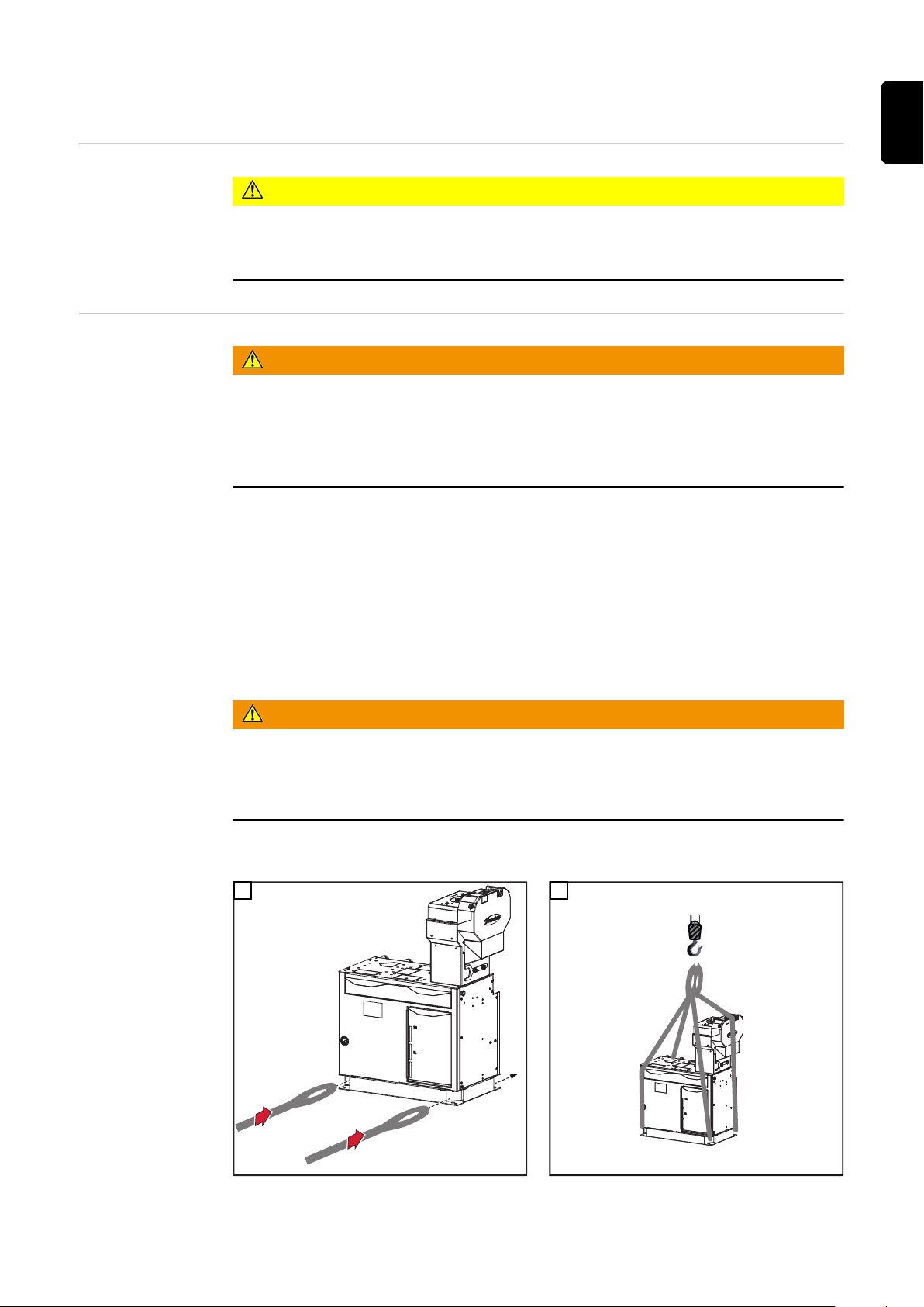
The welding torch service station can be lifted from the pallet and positioned at the installation site using a crane and two belts.
When selecting the belt length for this, ensure that the welding torch service station will
not be damaged when lifting down from the pallet.
WARNING!
Danger from falling objects.
May result in serious injuries or death.
The only form of crane transport permitted is lifting the device down from the pallet
▶
using a crane and belts.
Lifting Welding Torch Service Station from the Pallet using Crane and Belts
1 2
17

18

Operating controls, connections and
mechanical components
19

20
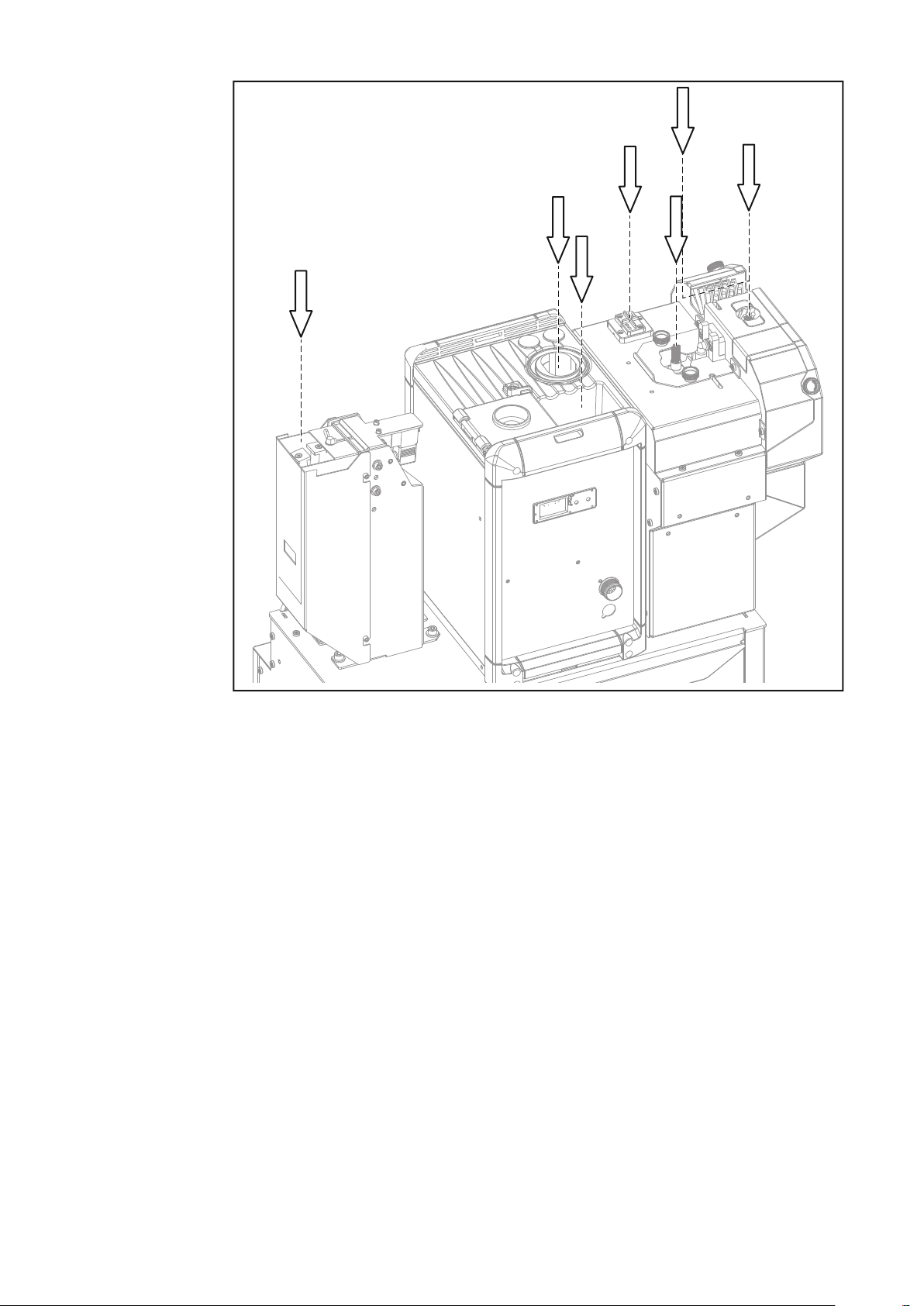
Operating controls, connections and mechanical
(1)
(2)
(3)
(4)
(5)
(6)
(7)
(8)
B
A
1
components
Detailed Information on the Optional Equipment
Safety
NOTE!
For detailed information on the optional equipment, consult the available installation instructions or Operating Instructions for the optional equipment.
Danger due to incorrect operation.
This can result in severe personal injury and damage to property.
▶
▶
EN-US
WARNING!
The functions described may only be used by trained personnel.
Do not perform the work described below until you have thoroughly read and under-
stood the following documents:
This document
All Operating Instructions for system components, especially the safety rules.
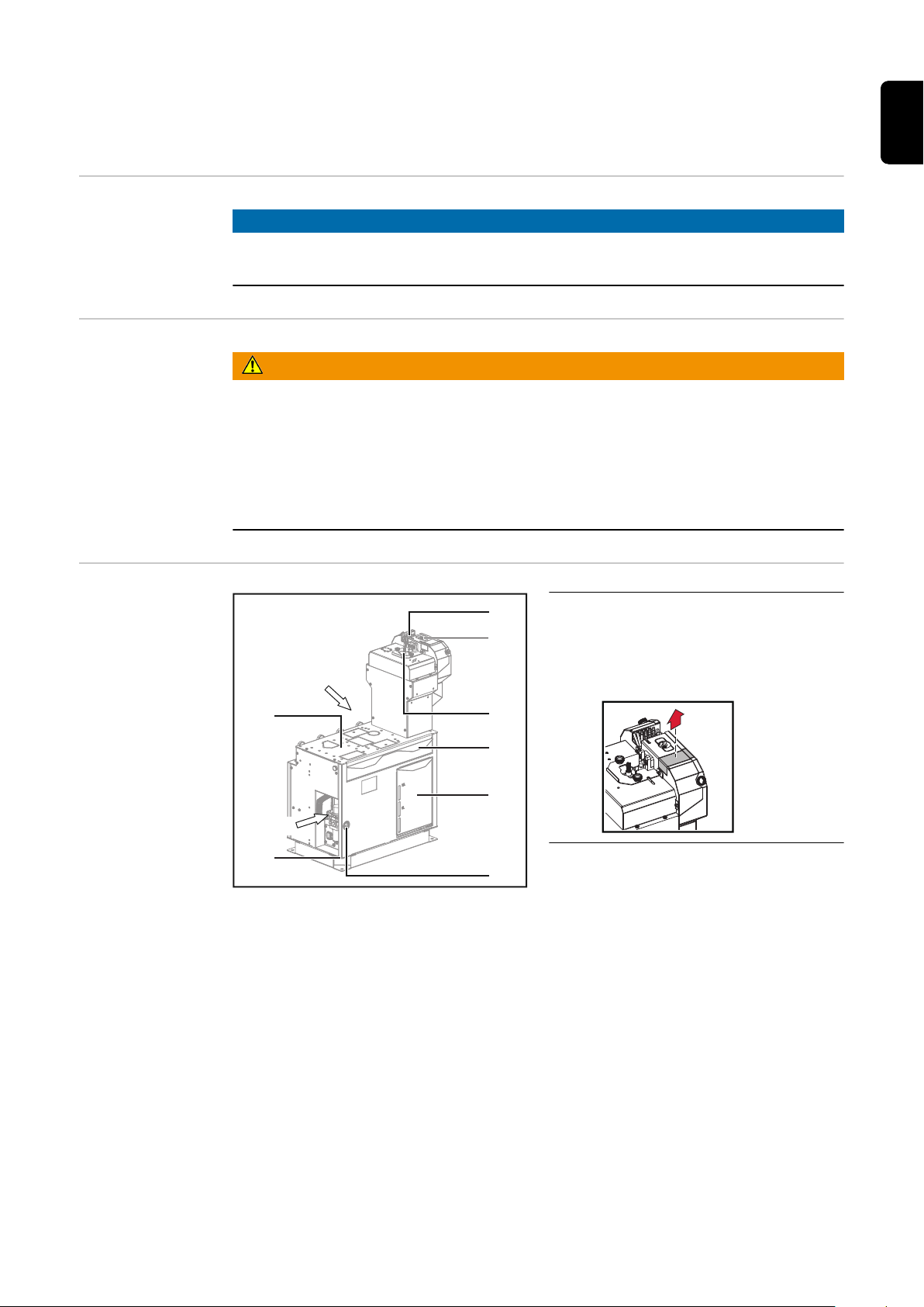
Connections and
mechanical components
(1) Outer gas nozzle cleaning brush
The second outer gas nozzle
cleaning brush can be released by
breaking away the metal parts
21

(2) High-pressure gas purging
1
1
(10)
(9)
Std. I/O
with parting agent
The opening for the high-pressure gas purging can be enlarged by breaking
away the metal parts, e.g., for oval gas nozzles.
(3) Inner gas nozzle cleaning brush
for cleaning the contact tip
(4) Collecting tray
(5) Flap for parting agent container
(6) Manometer
(7) Ground connection
(8) Installation area for optional equipment
(9) Robot control unit connection
Standard I/O, 37-pin
(10) Pressure regulator
Connection devices—supply air
Operating pressure 5.5–6 bar
View A
22

(16)
(15)
(14)
(13)
(12)
(11)
(18)
(17)
(19)
(21)
(20)
(11) External optional equipment
connection
(12) External optional equipment
connection
(13) External optional equipment
connection
(14) External optional equipment
connection
The 37-pin connections (11)–(14) for external optional equipment are equal.
EN-US
View B
(17) Compressed air connection
Nominal pressure 6 bar
(18) Compressed air connection
Nominal pressure 6 bar
(19) Compressed air connection
Nominal pressure 6 bar
(20) Parting agent connection
(21) Compressed air connection
Gas purging through hosepack, 16 bar
(15) Compressed air connection
Nominal pressure 6 bar
(16) Compressed air connection
Nominal pressure 6 bar
23

Connector pin assignments and signal descriptions
1234
9 8 7 6 5
101112131415
22 21 20 19 18 17 16
28 27 26 25 24 23
33 32 31 30 29
37 36 35 34
Safety
Assignment of
standard I/O connection for robot
control
WARNING!
Danger from incorrect operation and work that is not carried out properly.
This can result in serious personal injury and damage to property.
All the work and functions described in this document must only be carried out by
▶
technically trained and qualified personnel.
Read and understand this document in full.
▶
Read and understand all safety rules and user documentation for this equipment
▶
and all system components.
WARNING!
Danger due to machines starting automatically.
This can result in severe personal injury and damage to property.
The device must only be supplied with power using an emergency stop voltage cir-
▶
cuit.
CAUTION!
Danger from overcurrent.
Damage to the bearings may result.
Provide the power supply with 1.5 A fuse protection against overcurrent.
▶
To avoid interference, keep the line length between the welding torch service station and the robot control unit as short as possible.
Pin Signal
I 1 + 24 V DC
I 2 GND
NOTE!
I = Input:
from the robot control unit to the welding
torch service station
O = Output:
from the welding torch service station to
the robot control unit
24

I 3 High-end gas purging (from the front)
I 4 High-end gas purging (through the hosepack)
I 5 External valve brush cleaning
I 6 Internal valve brush cleaning
I 7 Pump for parting agent
8 NC
O 9 Pressure switch
O10 Parting agent fill level (optional)
11 Reserved
12 Reserved
O13 Gas nozzle free / cleaning ready (Braze +) / motor bottom / ready (TC
devices) - check, which signal belongs to which device
14 Reserved
I 15 Start cleaning (devices with 6-pin connector)
Clamp gas nozzle / cleaning motor on (devices with 17-pin connector)
16 Reserved
EN-US
I 17 Reserved
I 18 Reserved
O19 Reserved
O20 Reserved
O21 Cleaning error (TC devices); cleaning motor is running (RRV)
I 22 Spray In (TC devices);
spray parting agent at RRV (Twin / 70Han12P / Comfort);
adjust the measuring head on RRB+
O23 Ready (TC devices);
gas nozzle free at RRV (Twin / 70Han12P / Comfort);
gas nozzle free / motor bottom / cleaning ready for other devices
I 24 TC start cleaning
O25 TC parting agent low level OK
I 26 TC quick stop
27 NC
O28 RR Twin gas nozzle free
29 Reserved
30 Reserved
I 31 RR Twin start cleaning
32 Reserved
33 Reserved
25

I 34 WC cut wire electrode
1234
9 8 7 6 5
101112131415
22 21 20 19 18 17 16
28 27 26 25 24 23
33 32 31 30 29
37 36 35 34
I 35 Reserved
36 Reserved
37 NC
TC = Robacta TC 2000
WC = wire cutter
RR = Robacta Reamer
RRV = Robacta Reamer V
RRB+ = Robacta Reamer Braze+
Optional Connections Robot Control Unit (Fieldbus)
Assignment of
external optional
equipment connection
If the welding torch service station is equipped with an optional fieldbus as a robot control unit connection, then the connection is described in the separate Operating Instructions for the fieldbus:
42,0410,2245 ... ProfiNet Robacta TSS /i
42,0410,2434 … DeviceNet Robacta TSS /i
42,0410,2435 … ProfiBus Robacta TSS /i
42,0410,2436 … EtherCAT Robacta TSS /i
42,0410,2550 ... Ethernet IP Robacta TSS/i
CAUTION!
Danger from overcurrent.
Damage to the bearings may result.
Provide the power supply with 1.5 A fuse protection against overcurrent.
▶
NOTE!
To avoid interference, keep the line length between the welding torch service station and the robot control unit as short as possible.
26
I = Input:
from the optional equipment to the welding
torch service station
O = Output:
from the welding torch service station to
the optional equipment

Pin Signal
O 1 + 24 V DC
O 2 GND
3 NC
4 Occupied
5 Occupied
6 Occupied
7 Occupied
8 NC
9 Occupied
10 Occupied
I 11 Signal Gas OK Single
I 12 Signal Gas OK Twin
I 13 RR Single gas nozzle free
14 Reserved
O15 RR Single start cleaning
EN-US
16 Reserved
O17 Reserved
O18 Reserved
I 19 Reserved
I 20 Reserved
I 21 TC cleaning error
O22 TC spraying
I 23 TC ready
O24 TC start cleaning
I 25 TC agent low level OK
O26 TC quick stop
27 NC
I 28 RR Twin gas nozzle free
I 29 Reserved
30 Reserved
O31 RR Twin start cleaning
I 32 RR motor bottom
I 33 RR motor top
O34 WC / RR cut wire electrode
27

O35 RR clamp gas nozzle
O36 RR lifting device upwards
O37 Reserved
TC = Robacta TC 2000
WC = wire cutter
RR = Robacta Reamer
28

Installation and Startup
29

30

Safety
EN-US
Detailed Information on the Optional Equipment
Safety Please follow the safety rules below during all the tasks described in the "Installation and
NOTE!
For detailed information on the optional equipment, consult the available installation instructions or Operating Instructions for the optional equipment.
Commissioning" chapter.
WARNING!
Danger from incorrect operation and work that is not carried out properly.
This can result in severe personal injury and damage to property.
All work listed in these Operating Instructions may only be performed by trained spe-
▶
cialist personnel.
All functions described in these Operating Instructions may only be used by trained
▶
specialist personnel.
Do not perform the work or use the functions described below until you have thor-
▶
oughly read and understood the following documents:
these Operating Instructions,
all Operating Instructions for system components, especially the safety rules.
WARNING!
Danger due to machines starting automatically.
This can result in severe personal injury and damage to property.
In addition to these Operating Instructions, observe the safety rules of the robot
▶
manufacturer and welding system manufacturer.
For your personal safety, make sure that all protective measures have been taken in
▶
the robot's operating area and remain in effect while you are in this area.
WARNING!
Danger due to mechanically moving parts.
Serious injuries may result.
Before starting any work on the welding torch service station or the system compon-
▶
ents connected to it, disconnect the welding torch service station from the existing
compressed air supply, disconnect the existing options from the grid.
Ensure that the available compressed air supply to the welding torch service station
▶
and the electrical supply to the connected system components remain disconnected
until all work is finished.
31

WARNING!
Danger due
to flying parts (chips, metal particles, etc.),
escaping compressed air/parting agent mixture,
electrically supplied, activated options.
If compressed air is supplied to the welding torch service station, serious injury can result.
If work needs to be carried out on the device while the welding torch service station is
being supplied with compressed air or the optional equipment is being supplied with
electricity:
if there are TC cleaning units, keep all ferromagnetic parts (e.g., tools) away from
▶
the device
keep hands, hair, the face, items of property, and all items of clothing away from the
▶
optional devices
wear hearing protection
▶
wear protective goggles with side protection
▶
WARNING!
Danger due to insufficient ground conductor connection!
Serious injury or damage to property can result.
The housing screws are a suitable ground conductor connection for grounding the housing.
The housing screws must not under any circumstances be replaced by other screws
▶
without a reliable ground conductor connection.
32

Before installation
EN-US
Operating personnel, maintenance personnel
Setup Regulations
WARNING!
Danger due to machines starting automatically.
This can result in severe personal injury and damage to property.
In all situations, the device must only ever be operated by one person. In addition,
▶
make sure that there are no other people in the device's operating area while it is in
operation.
In all situations, the device must only ever be maintained by one person. In addition,
▶
make sure that there are no other people in the device's operating area while work
on it is ongoing.
The device has been tested according to protection class IP21. This means:
- Protection against contact with the fingers, protection against penetration of solid
foreign bodies with a diameter of more than 12.5 mm (0.49 in.)
- Protection against dripping water falling vertically
The device can be operated in accordance with protection class IP21.
Direct moisture (e.g. from rain) must be avoided.
NOTE!
Install the device at a minimum distance of 1 m (40 in.) away from IT equipment
and control lines, as well as from the welding process.
Specifications for
the Compressed
Air Supply
NOTE!
Install the device with an all-round clearance of at least 0.5 m (19.69 in.) to walls,
neighboring devices, or other objects.
NOTE!
Set up the device so that
welding spatter cannot hit the cleaning device,
▶
the device is accessible from all sides for maintenance and service work.
▶
To ensure the proper functioning of the cleaning device, fulfill the following specifications
for the compressed air supply:
- Set up a compressed air supply using the pressure relief valve and compressed air
filter
- Guarantee the compressed air quality in accordance with ISO 8573-1:2001, class 7
4 3, instrument air
-
Solid particle concentration £ 10 mg/m
- Pressure concentration point vapor £ + 3°C
-
Oil concentration £ 1 mg/m
3
3
33
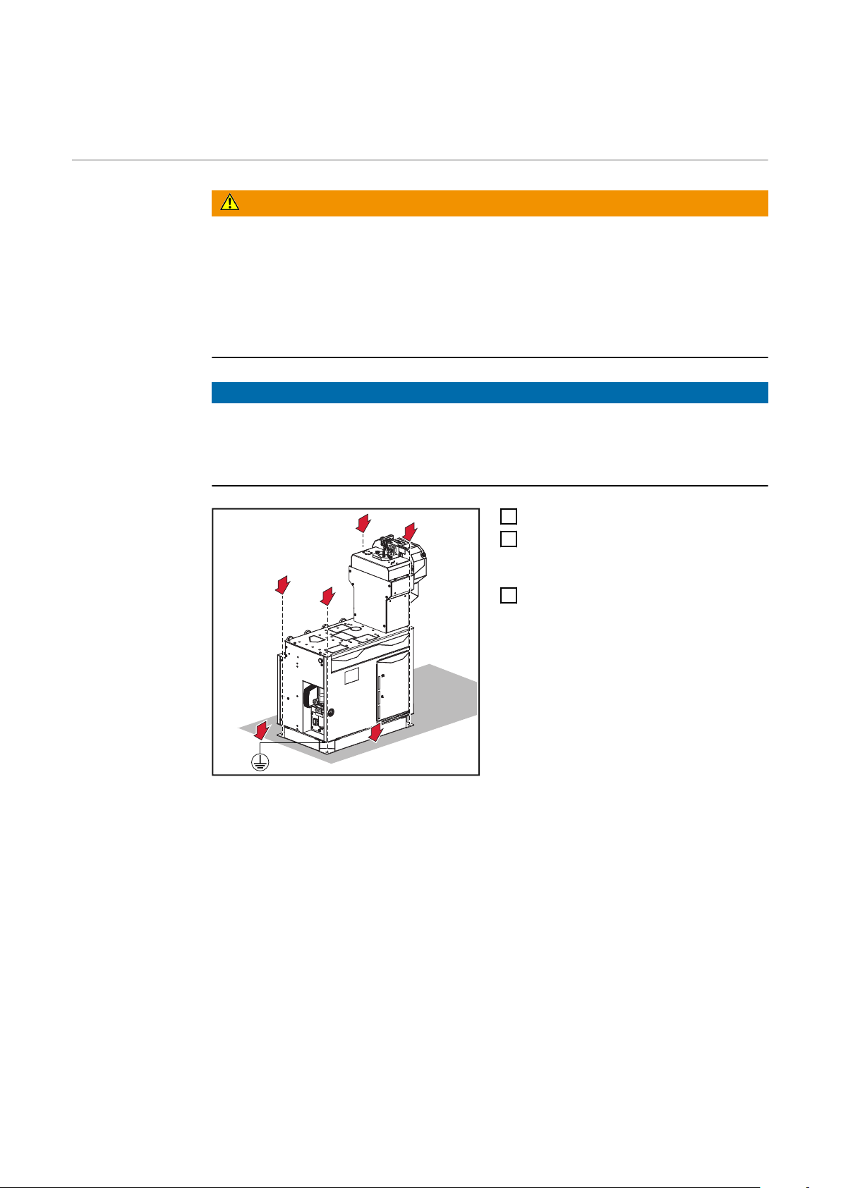
Bolting the Welding Torch Service Station to the
2
2
2
2
3
1
Surface
Bolting the Welding Torch Service
Station to the
Surface
WARNING!
Danger due to the welding torch service station toppling over.
It can cause injuries.
Even out any unevenness in the floor
▶
Set the service station up on an even, solid, and vibration-free surface or a corres-
▶
ponding base
Only set up the service station so that it is horizontal
▶
Use four screws to anchor the service station to the surface
▶
NOTE!
Depending on the surface, different dowels and screws may be required to anchor
the service station to the surface.
Therefore, dowels and screws are not part of the scope of supply for the service station.
The system installer is responsible for selecting the proper dowels and screws.
Position the service station
1
Use four dowels and four screws ap-
2
propriate for the surface to anchor the
service station to the surface
Ground the service station at its base
3
34

Installing Optional Equipment
EN-US
Optional Equipment on Delivery
Installing optional equipment overview
Depending on the configuration, optional equipment is installed on the welding torch service station on delivery.
The following installation descriptions apply for a welding torch service station without
optional equipment or for the retrofitting of the optional equipment.
The installation of the optional equipment available for the welding torch service station
is made up of the following sections:
1. Installing Touch Sense
2. Installing the wire cutter
3. Installing the cleaning unit
Robacta TC 2000
Robacta Reamer Twin
4. Installing the level sensor
5. Inserting the parting agent container
6. Installing the TCP tip
7. Installing the Robacta Reamer V Easy / Robacta Reamer V 70 Han12P
IMPORTANT! Follow the order listed here when installing the individual pieces of optional equipment!
35

1. Installing Touch Sense
2
1
1
2
2
2
2
3
2
6x TX25
5
4
Tools required - Torx screwdriver TX20
- Torx screwdriver TX25
- Size 17 mm wrench
- 4 mm Allen key
- Cable ties
- Diagonal cutting pliers
- Slotted screwdriver
- Hammer
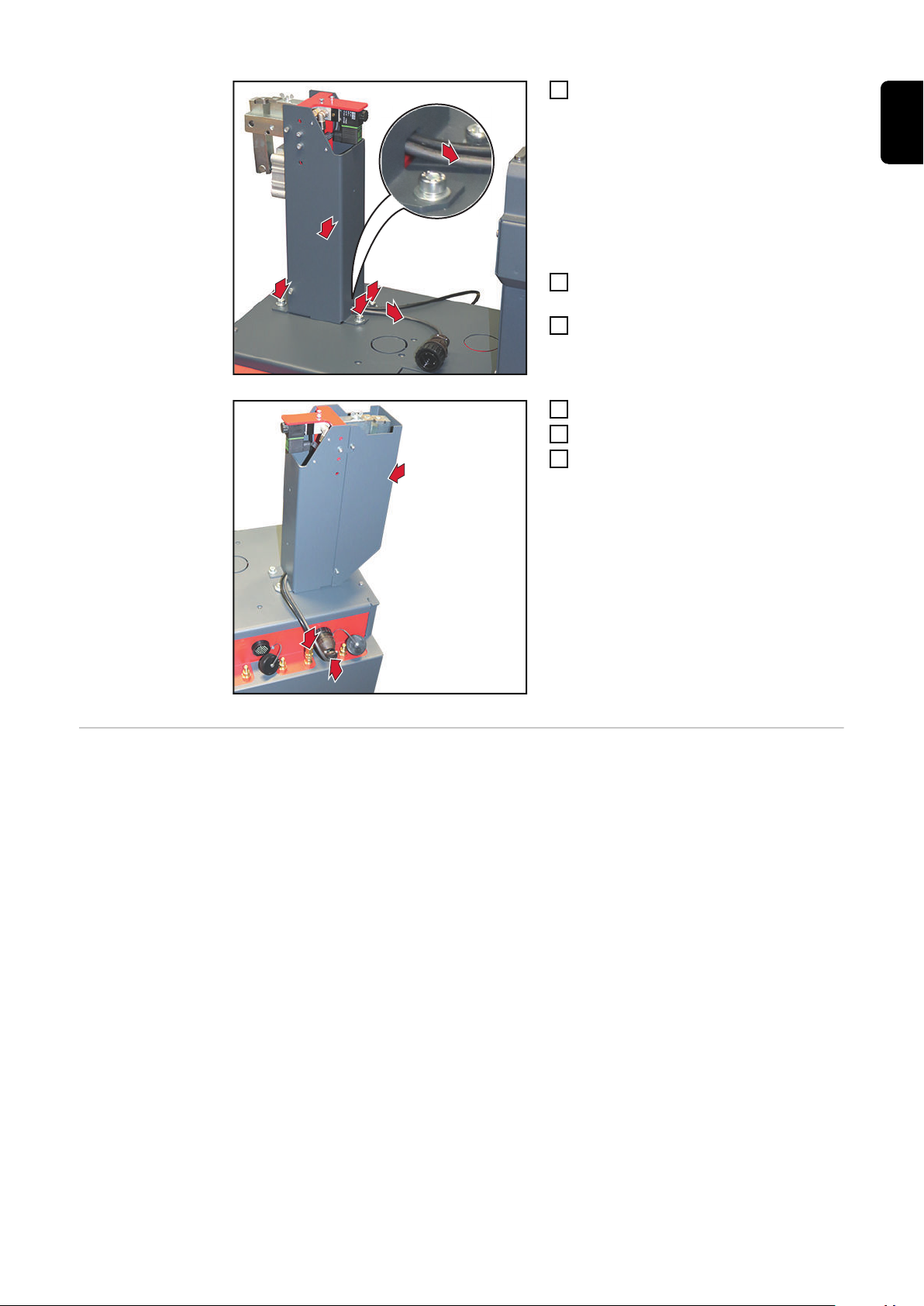
Installing Touch
Sense
Knock out the side round opening
1
Remove the 6 TX25 screws
2
Remove the cover
3
Knock out the top round opening
4
Remove the knocked-out material
5
from above
36

6
2 x TX20
7
7
Position the Touch Sense on the
9
8
10
10
2x TX20
1,4
1,8
2,2
2,6
1,4
1,8
2,2
2,6
1,4
1,8
2,2
2,6
1,4
1,8
2,2
2,6
6
plastic support
Secure the Touch Sense with 2 TX20
7
screws
Secure the cable to the bottom of the
8
Touch Sense with a 3 mm Allen screw
Insert the cable into the knocked-out
9
opening
EN-US
NOTE!
When installing the Touch Sense, do
not pinch, kink, shear off, or otherwise
damage the cable!
Install the Touch Sense on the service
10
station with 2 TX20 screws
The Touch Sense can be installed in
all 90° positions.
37

12
13
Insert the plastic insert into the open-
(1)
(2)
(3)
15
1
4
16
16
11
ing from the outside inwards
Use hexagonal nuts and wrench to at-
12
tach the plastic insert to the housing
wall
size 17 mm
Arrange serrated washer and cable
13
lug on the Allen screw according to
the diagram:
cable lug (1)—serrated washer (2)—
screw (3)
Screw the Allen screw into the plastic
14
insert
size 4 mm and then tighten
Fix the cable in place using 2 cable
15
ties
Trim cable ties
16
38
17
18
18
18
18
18
18
6x
TX25
*
Position cover
17
Install cover using 6 TX25 screws
18
Apply cable lug of an additional cable
19
to the screw protruding out of the
housing and use the serrated washer
and 8 mm hexagonal nut from the
scope of supply to secure the OPT/i
TSS TCP Touch Sense
Use the additional cable to establish a
20
connection to the workpiece/ground
EN-US
39
2. Installing the wire cutter
1
2
3
3
4
3
3
4
4
3
3
Tools Required - Slotted screwdriver
- Hammer
- 5 mm Allen key
- 6 mm Allen key
- 10 mm wrench
Additionally required
Installing the
Wire Cutter
The following accessories are required for attaching a wire cutter to the welding torch
service station:
OPT/i TSS Wire Cutter (installation set for wire cutter) ... 4,001,098,CK
Knock out the opening
1
Remove the knocked-out material
2
from above
Install the wire cutter on the wire cutter installation set:
using two 5 mm Allen screws and two
3
10 mm hexagonal nuts
using one 5 mm Allen screw and one
4
10 mm hexagonal nut
40
5
6
5
7
7
7
4x
Lay the control cable and compressed
8
10
9
5
air hose of the wire cutter backwards
through the recess
IMPORTANT! When positioning the
wire cutter, ensure that the control
cable and compressed air hose are
not pinched, kinked, cut, or otherwise
damaged.
Position the wire cutter according to
6
the diagram
Use four 6 mm Allen screws and four
7
washers to install the wire cutter on
the service station
Connect the control cable
8
Connect the compressed air hose
9
Apply the cover
10
EN-US
Operating Instructions
The wire cutter can be used to cut two wire electrodes with a diameter of up to 1.6 mm
(0.063 in.).
With the 0° welding torch, the wire electrodes must be cut one after the other.
The wire cutter is grounded.
41

3. Installing the Robacta TC 2000 cleaning unit
1
1
2
3
3
3
3
General A Robacta TC 2000 cleaning unit or a Robacta Reamer Twin cleaning unit can be moun-
ted on the service station.
Tools required - Torx screwdriver TX25
- 6 mm Allen key
- Slotted screwdriver
- Hammer
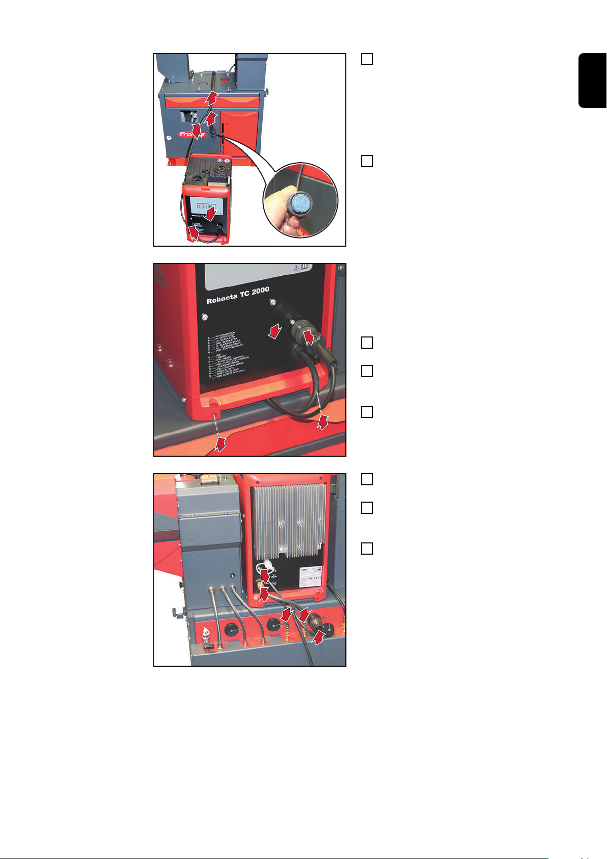
Additionally Required
Installing the
Robacta TC 2000
Cleaning Unit
The following accessories are required for installing a Robacta TC 2000 cleaning unit on
the welding torch service station:
OPT/i TSS TC2000 (installation set for Robacta TC 2000) ... 4,001,012,CK
Knock out the round opening
1
Position the mounting plate
2
Use four 6 mm Allen screws and four
3
washers to install the mounting plate
42
5
5
5
4
5
Place Robacta TC 2000 cleaning unit
6
8
7
7
4 x TX25
9
11
10
1
0
11
4
in front of the service station
IMPORTANT! When laying the control
cable, ensure that the correct cable
end is on the side of the TC 2000
cleaning unit.
Lay mains cable and control cable in
5
the mounting plate to the rear
IMPORTANT! When positioning the
Robacta TC 2000 cleaning unit, ensure
that the mains cable and control cable remain in the middle of the recess.
Apply Robacta TC 2000 cleaning unit
6
to the mounting plate
Use four TX25 screws to secure
7
Robacta TC 2000 cleaning unit to the
mounting plate
Connect control cable to the TC 2000
8
cleaning unit
EN-US
Attach control cable to the service sta-
9
tion
Connect hose for parting agent to the
10
service station and to the Robacta TC
2000 cleaning unit
Connect hose for compressed air to
11
the service station and to the Robacta
TC 2000 cleaning unit
43

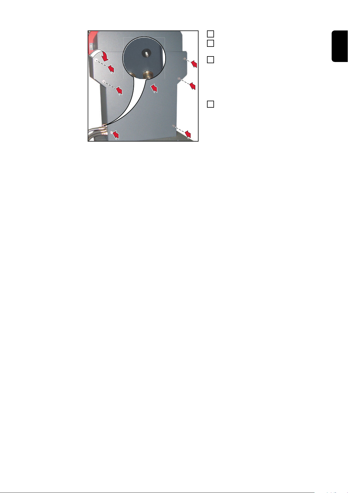
4. Installing the level sensor
1
2
2
2
3
2
2
2
3
3
3
3
3
4
5
4
6
7
7
Tools Required - Torx screwdriver TX25
- 5 mm wrench
Installing the
Level Sensor
Pull the spring pins of the collecting
1
tray to the left and right and swing collecting tray out
Remove three TX25 screws on the left
2
Remove three TX25 screws on the
3
right
Remove frame
4
Open flap for parting agent container
5
Apply level sensor to the threaded pin
6
on the flap
Use two 5 mm hexagonal nuts to se-
7
cure the level sensor
44

9
8
9
Guide the sensor cable through the re-
10
11
12
12
13
14
14
14
13
13
15
13
13
13
14
14
14
8
cess to the other side
Attach the sensor cable to the avail-
9
able cable piece
Close flap for parting agent container
10
IMPORTANT! When inserting the frame,
ensure that the metal strap is positioned in
the recess.
EN-US
Insert the frame
11
Lift up the frame
12
Use three TX25 screws to secure the
13
frame on the right
Use three TX25 screws to secure the
14
frame on the left
Pull spring pins and insert collecting
15
tray
Carry out the commissioning of the level sensor in accordance with the "Commissioning
level sensor" instructions (42,0410,2553).
The instructions are included in the scope of delivery of the level sensor.
45

5. Inserting the parting agent container
1
3
2
4
7
5
6
6
Inserting the
Parting Agent
Container
Open flap for parting agent container
1
Carefully pull hose out of the flap
2
Insert parting agent container until it
3
reaches the stop
Open the parting agent container
4
Insert the hose into the parting agent
5
container
Secure the cap of the hose
6
NOTE!
When closing the flap, ensure that the
hose is not pinched, kinked, cut, or otherwise damaged
Close flap for parting agent container
7
46

6. Installing the TCP Tip
2
2 x TX20
1
1
Tools Required - Torx screwdriver TX20
EN-US
Installing the TCP
Tip
TCP = Tool Center Point
Instead of the Touch Sense, a TCP tip can also be fitted.
This can be done without knocking out the round holes on the side and top.
Use 2 TX20 screws to install the TCP
1
tip on the service station
Unscrew the protective cap for opera-
2
tion
47

7. Installing the Robacta Reamer V Easy / Robacta
Reamer V 70 Han12P cleaning unit
General In addition to the Robacta TC 2000 or Robacta Reamer cleaning units, a Robacta Ream-
er V Easy cleaning unit or a Robacta Reamer V 70 Han12P cleaning unit for single welding torches can be mounted on the service station.
NOTE!
If the Robacta Reamer and Robacta Reamer V Easy / Robacta V 70 Han12P cleaning units are available on the service station, both cleaning units are always activated at the same time!
Robacta Reamer and Robacta Reamer V Easy / Robacta V 70 Han12P are both always
active.
Which of the two cleaning units is started up depends on the robot program.
▶
Tools required - 6 mm Allen key
- 10 mm wrench
- 19 mm wrench
Additionally required
Installing the
Reamer V Easy /
Robacta Reamer
V 70 Han12P
cleaning unit
The following accessories are required for installing a Robacta Reamer V Easy cleaning
unit on the welding torch service station:
OPT/i TSS Reamer Single... 4,001,123
The following accessories are required for installing a Robacta Reamer V 70 Han12P
cleaning unit on the welding torch service station:
OPT/i TSS Reamer V70 ... 4,001,133
NOTE!
The assembly of Robacta Reamer V Easy and Robacta Reamer V 70 Han12P is
identical.
All work steps for Robacta Reamer V Easy also apply to Robacta Reamer V 70 Han12P.
48

1
Example: Service station with Robacta reamer and
2
3
3
3
3
4
5
4
4
6
wire cutter
Position the intermediate plate over
1
the 4 holes
Place the Robacta Reamer V Easy on
2
the intermediate plate
Use four 6 mm Allen screws and four
3
washers to install the Robacta Reamer V Easy on the service station
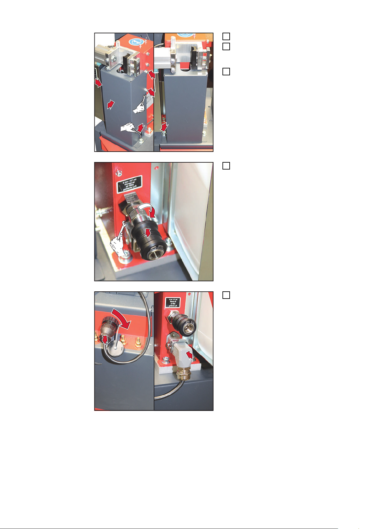
EN-US
Remove three 10 mm hexagonal bolts
4
Remove the cover
5
Knock out the rectangular opening
6
49
7
8
8
9
8
9
Fit the new cover
10
11
11
7
Install the new cover on the Robacta
8
Reamer V Easy with three 10 mm
hexagonal bolts
Secure the new cover to the service
9
station with two 6 mm Allen screws
Install spool valve
10
Size 19 mm
Connect the control cable to the ser-
11
vice station and Robacta Reamer V
Easy
50

1
2
12
Connect the compressed air supply
12
EN-US
51
Starting Up the Welding Torch Service Station
*
4
3
2
1
3
3
2
2
General
Opening the
Welding Torch
Service Station
NOTE!
If wetting agent has not been applied to the inside of the welding torch, this may
lead to the permanent contamination of the welding torch when welding begins.
Always wet the inside of the welding torch with the manufacturer's "Robacta Reamer"
parting agent before starting an automatic application.
To achieve optimum cleaning results, observe the following points:
- Always wet the inside of the welding torch with parting agent
- Adhere to the specified cleaning procedures
- Adhere to the specified cleaning positions
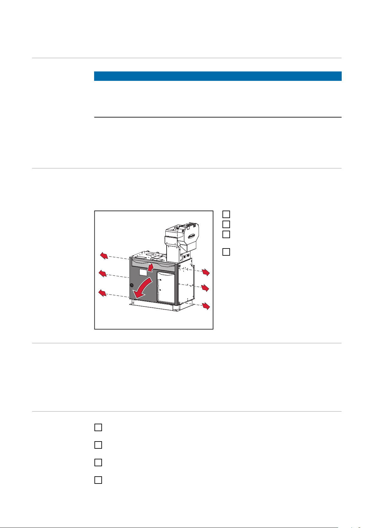
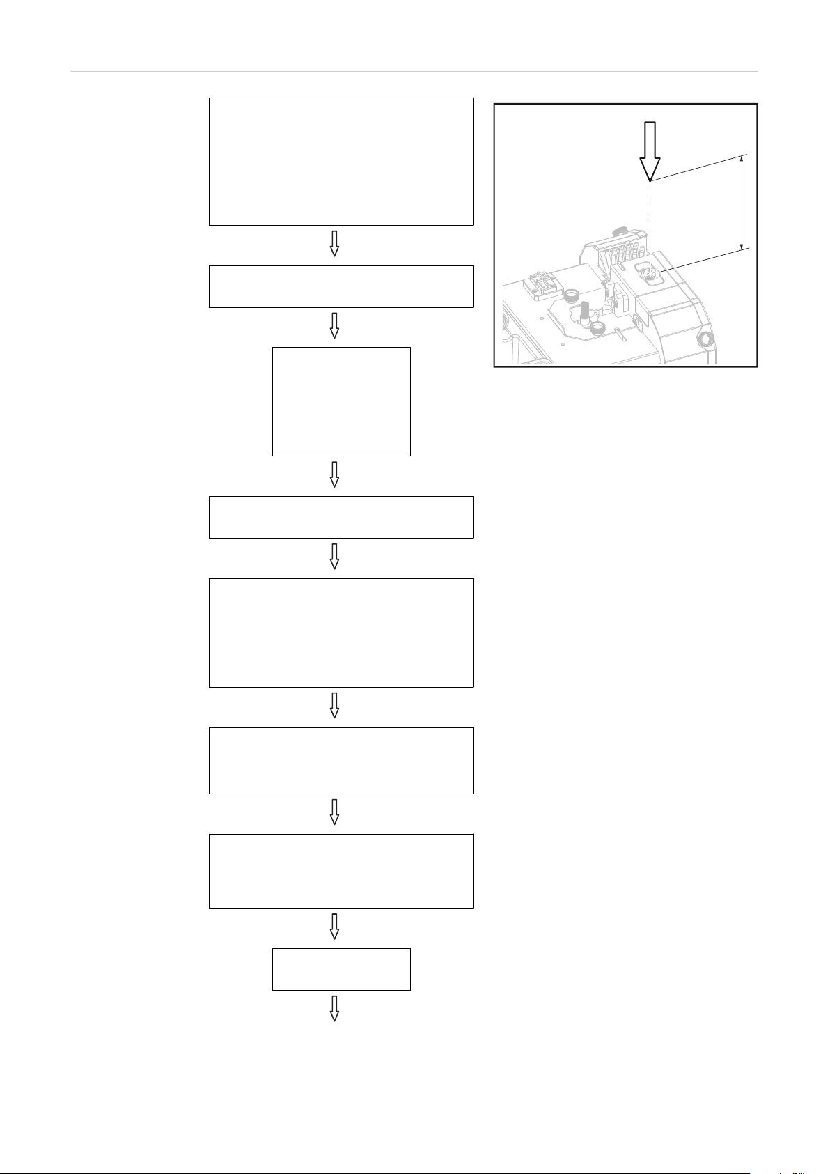
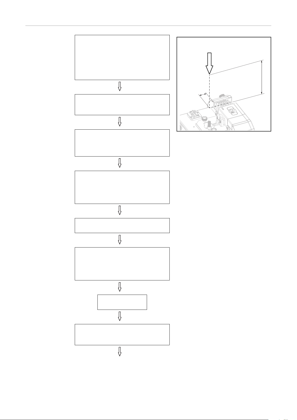
If the welding torch service station is equipped with an optional fieldbus as a robot control unit connection, the service station for connecting the robot control unit and for fault
diagnosis of the fieldbus must be opened as follows:
Remove collecting tray
1
Remove three TX25 screws on the left
2
Remove three TX25 screws on the
3
right
Remove frame
4
* Position of the bus coupler
Requirements for
Starting Up
The following requirements must be met in order to commission the cleaning device:
- Securely bolt the welding torch service station to the surface
- Any available optional equipment installed on the welding torch service station, supplied with compressed air and connected to the grid if necessary
- Compressed air supply to the welding torch service station established
- Cleaning device connected to the robot control unit
Starting Up the
Welding Torch
Service Station
Check whether all optional equipment is correctly connected to the welding torch
1
service station
Connect welding torch service station to the robot control unit
2
max. length of the control cable = 30 m
Establish electrical supply to the optional equipment
3
max. length of the mains cable = 30 m
Establish compressed air supply
4
max. length of the compressed air supply line = 30 m
52

Adjust pressure on the manometer: 5.5–6 bar
5
Check that all equipment parts and covers are correctly installed
6
IMPORTANT! Before welding for the first time, a complete cleaning process must be car-
ried out.
EN-US
53

54

Cleaning Program Sequence
55

56

Program sequence—overview
EN-US
Detailed Information on the Optional Equipment
Program Sequence—Overview
NOTE!
For detailed information on the optional equipment, consult the available installation instructions or Operating Instructions for the optional equipment.
The following program sequence is described using the example of a service station with
wire cutter, Robacta TC 2000 cleaning unit, and dipping bowl.
For other configurations, refer to the Operating Instructions of the components.
- Welding
Pos. A Wire cutter + retract wire
Pos. B Robacta TC 2000 dipping bowl
Pos. C Robacta TC 2000
Pos. D High-pressure gas purging with parting agent (1st contact tip)
Pos. E Outer gas nozzle cleaning brush (2x)
Pos. F Inner gas nozzle cleaning brush (1st and 2nd contact tip )
Pos. D High-pressure gas purging with parting agent (2nd contact tip)
Pos. G Touch Sense + wire threading
or
Pos. A Wire cutter + wire threading
- Welding
57
A
B
C
D
E
F
G
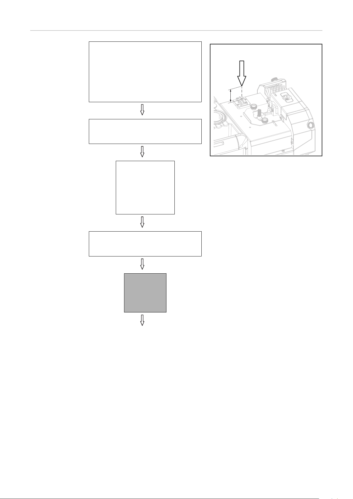
58

General information
max. 75 mm
(2.95 in.)
(1)
Wire cutter The wire cutter can be used to cut two wire electrodes with a diameter of up to 1.6 mm
(0.063 in.)
The opening and closing of the wire cutter is triggered by an active signal from the robot
controls.
EN-US
TC 2000 dipping
bowl
The use of the dipping bowl is recommended in the case of:
- gas-cooled welding torches
- water-cooled welding torches in the higher power range (hot gas nozzles)
Advantages:
- The spatter accumulation on the gas nozzle loosens.
- The welding torch is also cooled.
- The anti-stick agent contained in the parting agent prevents new contaminations.
NOTE!
Immerse welding torch a maximum of
75 mm (2.95 in.) into the dipping bowl.
The gas holes (1) must remain dry.
▶
Robacta TC 2000 Robacta TC 2000 is an electromagnetic cleaning unit for welding torch cleaning in steel
applications.
After 50 seconds of charging time, the maximum magnetic flux density is available for
the cleaning process.
The cleaning process (discharge process) is initiated by the “Cleaning start” signal.
Specification of
the Parting Agent
Volume
Cleaning End
without Touch
Sense Option
In the case of high-pressure gas purging with parting agent, the parting agent volume is
specified via the duration of the external “Pump for parting agent” signal.
The longer the signal is present, the more parting agent is injected.
If the Touch Sense option is not installed on the service station, then the cleaning process is ended at the wire cutter.
59

Program sequence
A
50 mm
1.97 in.
Wire cutter program sequence
Start
Move to position A
approx. 50 mm/1.97 in. above wire cutter (between blades and sheet metal
cover)
Speed: High-speed mode
Set
"Start wirefeeding" signal on the power
source
Wait approx. 0.5
seconds
Reset
"Start wirefeeding" signal on the power
source
Move in with the wire electrode in the
wire cutter blade
Speed: 50 cm/min (19.69 ipm)
Set
external signal "Cut wire electrode"
Move straight up
approx. 50 mm/1.97 in. above wire cutter blades
Speed: 50 cm/min (19.69 ipm)
Wait 0.5 seconds
60

Reset
external signal "Cut wire electrode"
Set
"Retract wire electrode" signal on the
power source
Reset
"Retract wire electrode" signal on the
power source
Wait approx. 2-3
seconds
EN-US
61

Robacta TC 2000
B
50 mm
1.97 in.
75 mm
2.95 in.
dipping bowl program sequence
Move to position B
approx. 200 mm/7.9 in. centrally above
dipping bowl
Speed: High-speed mode
Move into dipping bowl
max. speed: 50 cm/min / 19.69 ipm
max. insertion depth: 75 mm / 2.95 in.
Wait 2-3 seconds
Move to position B
approx. 200 mm/7.9 in. centrally above
dipping bowl
max. speed: 50 cm/min (19.69 ipm)
Set
gas purging through welding torch (option)
Reset
Wait 0.5 seconds
Max. insertion depth
gas purging through welding torch (option)
62

TC 2000 program
C
50 mm
1.97 in.
sequence
Move to position C
approx. 50 mm/1.97 in. centrally above
cleaning coil
Speed: High-speed mode
EN-US
Move into TC 2000
max. speed: 50 cm/min / 19.69 ipm
Insertion depth: 54 mm / 2.13 in. *)
Set
external signal "Start cleaning"
Wait 0.5 seconds
Reset
external signal "Start cleaning"
Move to position C
approx. 50 mm/1.97 in. centrally above
cleaning coil
max. speed: 50 cm/min (19.69 ipm)
*) Insertion depths for coil shapes
other than Twin as per Robacta
TC 2000 Operating Instructions
63
High-pressure
D
50 mm
1.97 in.
gas purging with
parting agent
program sequence (1st contact tip)
Move to position D
1
approx. 50 mm/1.97 in. centrally above
the opening for the high-pressure gas
purging
Contact tip 1 vertical to the service station
Speed: High-speed mode
Set
external signal "Pump for parting agent"
Wait 0.2-0.3
seconds
specification of the
parting agent
volume via the dur-
ation
Reset
external signal "Pump for parting agent"
Move into the high-pressure gas purging
max. speed: 50 cm/min / 19.69 ipm
Select insertion depth so that the distance between contact tip and nozzle is
3 mm / 0.12 in.
Set
64
external signal "External valve brush
cleaning"
Set
external signal "High-end gas purging
(from front)"
Wait 0.5 - 1.5
seconds

Reset
external signal "High-end gas purging
(from front)"
EN-US
Reset
external signal "External valve brush
cleaning"
Wait 1 second
65
Outer gas
E
50 mm
1.97 in.
20 mm
0.79 in.
nozzles cleaning
brush program
sequence
Move to position E
approx. 50 mm/1.97 in. centrally above
the outer gas nozzle cleaning brush and
approx. 20 mm/0.79 in. in front of the
housing of the service station
Position welding torch at an angle
Speed: High-speed mode
Set
external signal "External valve brush
cleaning"
Move into the external gas nozzle
cleaning brush
max. speed: 50 cm/min / 19.69 ipm
max. insertion depth: 12 mm / 0.47 in.
Pass through the external gas nozzle
cleaning brush x2
forwards and backwards
max. speed: 50 cm/min / 19.69 ipm
max. insertion depth: 12 mm / 0.47 in.
Turn welding torch 180°
*)
Pass through the external gas nozzle
cleaning brush x2
forwards and backwards
max. speed: 50 cm/min / 19.69 ipm
max. insertion depth: 12 mm / 0.47 in.
*) Alternative:
Break the second cleaning brush free
and pass through each cleaning brush x
1
66
Wait approx. 2-3
seconds
Reset
external signal "External valve brush
cleaning"

Move to position E
approx. 50 mm/1.97 in. centrally above
the outer gas nozzle cleaning brush and
approx. 20 mm/0.79 in. in front of the
housing of the service station
max. speed: 50 cm/min (19.69 ipm)
EN-US
67

Inner gas nozzle
50 mm
1.97 in.
F
cleaning brush
program sequence
Move to position F
1
approx. 50 mm/1.97 in. centrally above
the inner gas nozzle cleaning brush
Contact tip 1 vertical to the service station
Speed: High-speed mode
Set
external signal "Internal valve brush
cleaning"
Move into the inner gas nozzle cleaning brush
max. speed: 50 cm/min / 19.69 ipm
max. insertion depth: 1/3 of the brush
length
Wait 2-3 seconds
Move to position F
2
approx. 50 mm/1.97 in. centrally above
the inner gas nozzle cleaning brush
Contact tip 2 vertical to the service station
max. speed: 50 cm/min (19.69 ipm)
Move into the inner gas nozzle cleaning brush
max. speed: 50 cm/min / 19.69 ipm
max. insertion depth: 1/3 of the brush
length
Wait 2-3 seconds
Move to position F
approx. 50 mm/1.97 in. centrally above
the inner gas nozzle cleaning brush
Contact tip 2 vertical to the service station
max. speed: 50 cm/min (19.69 ipm)
68

Reset
external signal "Internal valve brush
cleaning"
EN-US
69
High-pressure
D
50 mm
1.97 in.
gas purging with
parting agent
program sequence (2nd contact tip)
Swivel to position D
2
Contact tip 2 vertical to the service station
max. speed: 50 cm/min (19.69 ipm)
Set
external signal "Pump for parting agent"
Wait 0.2 - 0.3
seconds
specification of
the parting agent
volume via the
duration
Reset
external signal "Pump for parting agent"
Move into the high-pressure gas purging
max. speed: 50 cm/min / 19.69 ipm
Select insertion depth so that the distance between contact tip 2 and nozzle
is 3 mm / 0.12 in.
Set
external signal "High-end gas purging
(from front)"
Set
external signal "External valve brush
cleaning"
Wait 0.5 - 1.5
seconds
Reset
external signal "High-end gas purging
(from front)"
70

Wait 1 second
Reset
external signal "External valve brush
cleaning"
Move to position D
2
approx. 50 mm/1.97 in. centrally above
the opening for the high-pressure gas
purging
Contact tip 2 vertical to the service station
max. speed: 50 cm/min (19.69 ipm)
EN-US
71
Touch Sense (op-
G
x mm
x in.
tion) program sequence
Move to position G
x mm/x in. centrally above the Touch
Sense option
x = stick out of the wire electrodes depending on application
Speed: High-speed mode
Set
"Wirefeeding on" signal on the power
source
Wait until the wire
electrode touches
the Touch Sense
option - the
wirefeeding is
automatically
stopped
Reset
"Wirefeeding on" signal on the power
source
End of the
cleaning
process
Welding
72

Wire cutter -
A
50 mm
1.97 in.
cleaning end program sequence
Inner gas nozzle cleaning brush
EN-US
Move to position A
approx. 50 mm/1.97 in. above wire cutter (between blades and sheet metal
cover)
Speed: High-speed mode
Set
"Start wirefeeding" signal on the power
source for approx. 2.5—4.5 seconds
(approx. 20% longer than retracting the
wire)
Wait 2.5 - 4.5
seconds
Reset
"Start wirefeeding" signal on the power
source
Move into wire cutter
insertion depth = x mm above the cutting tool
x = stick out of the wire electrodes depending on application
max. speed: 50 cm/min (19.69 ipm)
Set
external signal "Cut wire electrode"
Wait 0.5 seconds
Move straight up
approx. 50 mm/1.97 in. centrally above
wire cutter blades
Speed: 50 cm/min (19.69 ipm)
73

Reset
external signal "Cut wire electrode"
End of the
cleaning
process
Welding
74

Troubleshooting, Maintenance, and
Disposal
75

76

Safety
EN-US
Detailed Information on the Optional Equipment
Safety Please follow the safety rules below during all the tasks described in the "Installation and
NOTE!
For detailed information on the optional equipment, consult the available installation instructions or Operating Instructions for the optional equipment.
Commissioning" chapter.
WARNING!
Danger from incorrect operation and work that is not carried out properly.
This can result in severe personal injury and damage to property.
All work listed in these Operating Instructions may only be performed by trained spe-
▶
cialist personnel.
All functions described in these Operating Instructions may only be used by trained
▶
specialist personnel.
Do not perform the work or use the functions described below until you have thor-
▶
oughly read and understood the following documents:
these Operating Instructions,
all Operating Instructions for system components, especially the safety rules.
WARNING!
Danger due to machines starting automatically.
This can result in severe personal injury and damage to property.
In addition to these Operating Instructions, observe the safety rules of the robot
▶
manufacturer and welding system manufacturer.
For your personal safety, make sure that all protective measures have been taken in
▶
the robot's operating area and remain in effect while you are in this area.
WARNING!
Danger due to mechanically moving parts.
Serious injuries may result.
Before starting any work on the welding torch service station or the system compon-
▶
ents connected to it, disconnect the welding torch service station from the existing
compressed air supply, disconnect the existing options from the grid.
Ensure that the available compressed air supply to the welding torch service station
▶
and the electrical supply to the connected system components remain disconnected
until all work is finished.
77

WARNING!
Danger due
to flying parts (chips, metal particles, etc.),
escaping compressed air/parting agent mixture,
electrically supplied, activated options.
If compressed air is supplied to the welding torch service station, serious injury can result.
If work needs to be carried out on the device while the welding torch service station is
being supplied with compressed air or the optional equipment is being supplied with
electricity:
if there are TC cleaning units, keep all ferromagnetic parts (e.g., tools) away from
▶
the device
keep hands, hair, the face, items of property, and all items of clothing away from the
▶
optional devices
wear hearing protection
▶
wear protective goggles with side protection
▶
WARNING!
Danger due to insufficient ground conductor connection!
Serious injury or damage to property can result.
The housing screws are a suitable ground conductor connection for grounding the housing.
The housing screws must not under any circumstances be replaced by other screws
▶
without a reliable ground conductor connection.
78

Troubleshooting
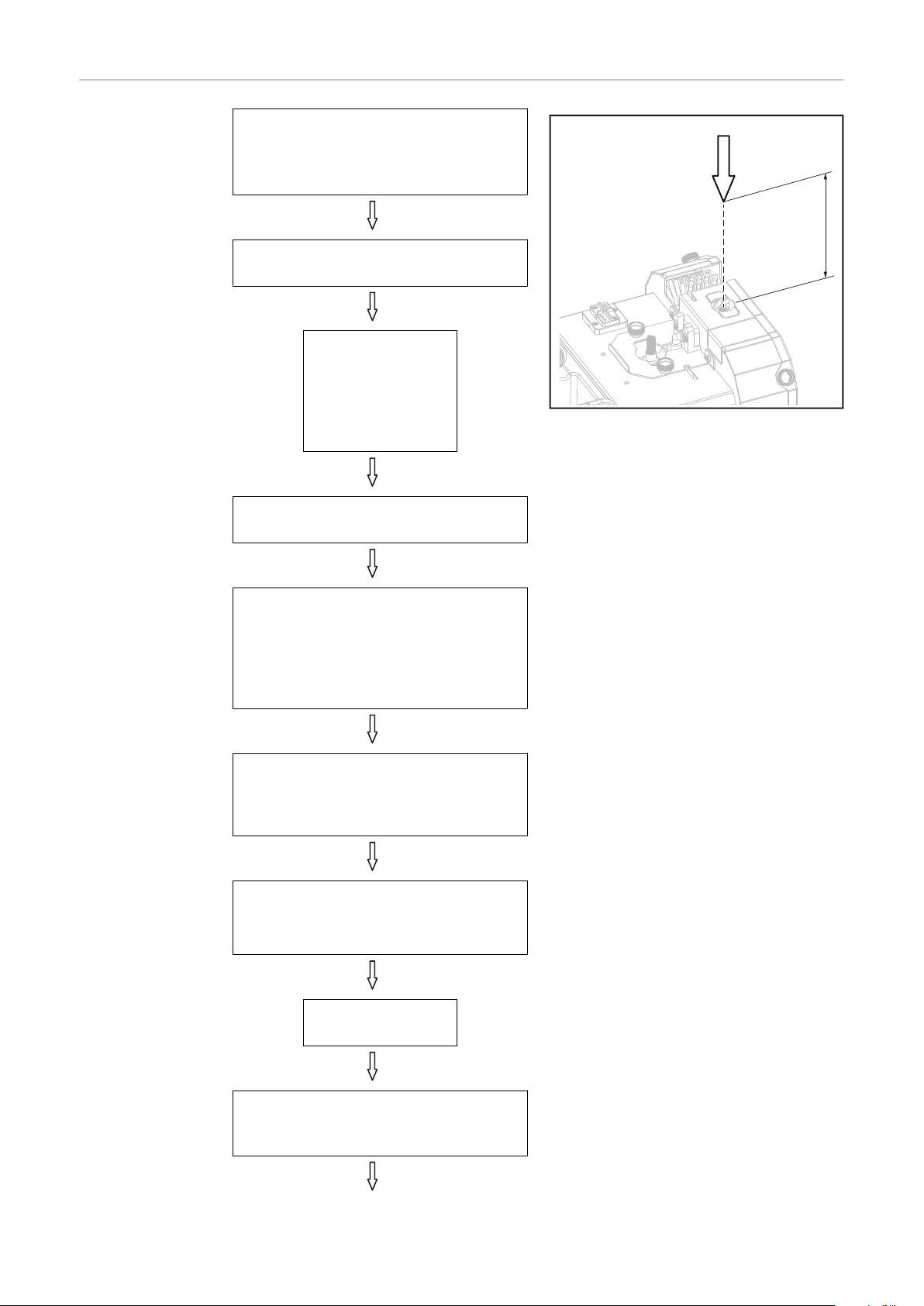
*
2
3
4
1
EN-US
Detailed Information on the Optional Equipment
NOTE!
For detailed information on the optional equipment, consult the available installation instructions or Operating Instructions for the optional equipment.
Troubleshooting Make a note of the serial number and configuration of the device, and provide the ser-
vice team with a detailed error description if:
- Errors occur that are not covered in this document
- The troubleshooting measures provided in this document are unsuccessful
Parting agent is not injected
Cause:
Remedy:
Cause:
Remedy:
Cause:
Remedy:
Parting agent container is empty
Insert new parting agent canister
Injection quantity too low
Set injection quantity (injection time)
Intake filter in "Robacta Reamer" parting agent container dirty
Blow out the intake filter in the "Robacta Reamer" parting agent container
from the inside out with compressed air using the intake hose:
Cause:
Remedy:
Cause:
Remedy:
Cause:
Remedy:
Cause:
Remedy:
Cause:
Remedy:
Cause:
Remedy:
Parting agent hose kinked
Remove kink, if necessary replace hose
Parting agent pump faulty
Contact After-Sales Service
No signal at the parting agent pump
Check programming;
Check connections to the robot control unit
Non-return value faulty
Contact After-Sales Service
Compressed air supply interrupted
Set up the compressed air supply
Compressed air supply line faulty or dirty
Clean compressed air supply line and replace if necessary
79

Cleaning brushes do not run
Cause:
Remedy:
Compressed air supply interrupted
Set up the compressed air supply
Cause:
Remedy:
Cause:
Remedy:
Cause:
Remedy:
Cause:
Remedy:
High-pressure gas purging not working
Cause:
Remedy:
Cause:
Remedy:
Cause:
Remedy:
Compressed air supply line faulty or dirty
Clean compressed air supply line and replace if necessary
Brush motor faulty
Inform service team
Valve faulty
Inform service team
No signal at the valve
Check programming;
Check connections to the robot control unit
Compressed air supply interrupted
Set up the compressed air supply
Compressed air supply line faulty or dirty
Clean compressed air supply line and replace if necessary
Pressure regulator not set correctly
Check pressure at pressure regulator, set pressure to 5.5 - 6 bar
Cause:
Remedy:
Cause:
Remedy:
Cause:
Remedy:
Cause:
Remedy:
Pores in the weld seam
Cause:
Remedy:
Cause:
Remedy:
Pressure booster faulty
Contact After-Sales Service
Inlet pressure at the pressure booster too low
Check inlet pressure
Valve faulty
Contact After-Sales Service
Nozzle blocked
Clean nozzle, replace if necessary
Too much parting agent in the inside of the welding torch
Remove residues of parting agent by blowing out the inside of the welding
torch. Ensure supply of compressed air
Too much parting agent in the inside of the welding torch
Reduce parting agent injection quantity (shorten duty cycle of pump for parting agent)
80
Service, maintenance and disposal
2
1
EN-US
Detailed Information on the Optional Equipment
Releasing Pressure before Maintenance Work
NOTE!
For detailed information on the optional equipment, consult the available installation instructions or Operating Instructions for the optional equipment.
WARNING!
Danger due to compressed air stored at 16 bar in the pressure booster.
Serious injuries may result.
Switch off the compressed air supply and release stored compressed air before
▶
maintenance and servicing.
During maintenance and servicing, keep the device de-energized and depressur-
▶
ized.
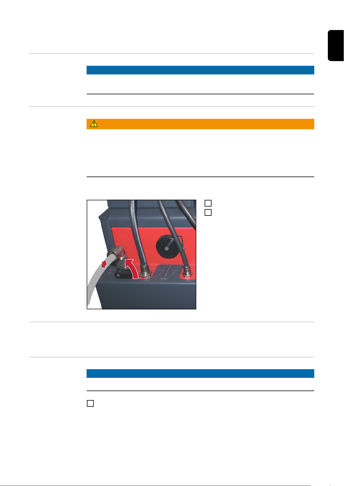
Release pressure:
Disconnect compressed air supply
1
Open valve
2
Fully release pressure
Before Every
Start-up
Daily
- Check the fill level in the parting agent container and top up if necessary
- Check cleaning brushes for contamination and wear; replace them if necessary
NOTE!
Only clean the devices with cleaning products that are free of solvents.
Remove any deposited parting agent and contamination from the outside of the base
1
unit and cleaning unit.
81

Weekly - Empty collecting tray;
clean screen for collecting tray if available
- Blow out the intake filter in the parting agent container from the inside out with compressed air using the intake hose
- Drain water in the pressure booster (press red button on the glass tank)
Monthly - Open the dirt deflector under the round brushes and clean with compressed air
Every 6 Months
Risk of damage to electronic parts.
▶
1
Every 12 Months
Disposal Materials should be disposed of according to valid local and national regulations.
1
CAUTION!
Do not blow electronic parts clean from a short distance away.
Open the welding torch service station and blow clean with dry and reduced compressed air
Have a Fronius service technician perform a safety inspection on the cleaning device
82

Change cleaning brushes and nozzle for the high-
2
1
2
1
1
pressure gas purging
Releasing Pressure before Maintenance Work
Danger due to compressed air stored at 16 bar in the pressure booster.
Serious injuries may result.
▶
▶
Release pressure:
WARNING!
Switch off the compressed air supply and release stored compressed air before
maintenance and servicing.
During maintenance and servicing, keep the device de-energized and depressurized.
Disconnect compressed air supply
1
Open valve
2
Fully release pressure
EN-US
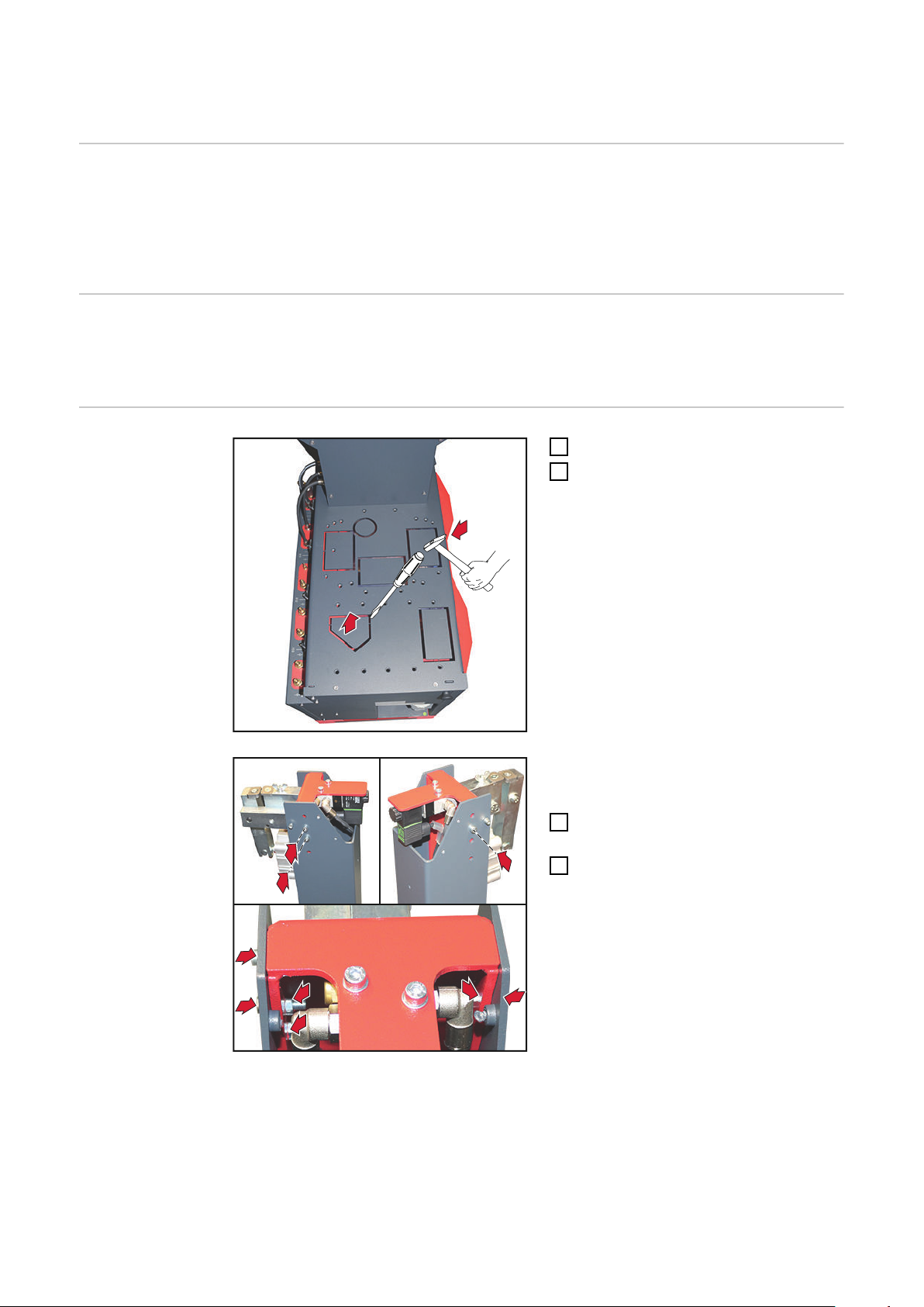
Replacing the
Outer Gas Nozzle
Cleaning Brushes
Loosen knurled screws
1
Remove cover
2
83

3
Remove installation wrench
6
4
5
7
2
1
1
3
Place the installation wrench behind
4
the right-hand cleaning brush
Undo the 17 mm hexagonal bolt
5
Remove hexagonal bolt and fixing
6
washer
Remove right-hand cleaning brush
7
Replacing the inner gas nozzle
cleaning brush
Repeat steps 4 - 7 for the left-hand
8
cleaning brush
NOTE!
Always replace both cleaning brushes!
The assembly of the cleaning brushes is carried out in reverse order.
Loosen knurled screws
1
Remove cover
2
84

3
4
Press and hold locking button
2
1
1
3
4
3
Remove cleaning brush from above
4
Changing the
nozzle for the
high-pressure
gas purging
IMPORTANT! During installation, press
and hold the locking button and insert the
cleaning brush until it engages.
Loosen knurled screws
1
Remove cover
2
EN-US
Pull out spring bolt
3
Remove the nozzle from above
4
85

Fitting the nozzle:
IMPORTANT! When fitting the nozzle, ensure that:
- The O-ring on the nozzle is present and OK
- The O-ring is greased
CAUTION!
Danger from nozzle being thrown out of the device.
An incorrectly secured nozzle can be thrown out of the device when compressed air is
supplied and cause a variety of injuries.
The sequence of the following steps must be observed.
▶
Always insert the nozzle as far as it will go.
▶
Check that the nozzle is correctly secured.
▶
Pull out and hold the spring bolt
1
Insert the nozzle as far as it will go
2
Release the spring bolt and make sure it engages
3
Fit cover
4
86

Appendix
87

88

Technical data
EN-US
Detailed Information on the Optional Equipment
Robacta TSS /i
NOTE!
For detailed information on the optional equipment, consult the available installation instructions or Operating Instructions for the optional equipment.
Supply voltage 24 V DC
Nominal output 24 W
Compressed air supply 6 bar
86.99 psi
Minimum cleaning interval From 20 s
Degree of protection IP 21
Dimensions l/w/h 765/405/1000 mm
30.1/15.9/39.4 in.
Weight (without optional equipment, incl.
10 l parting agent canister)
EMC device class A
Mark of conformity CE
82 kg
180.78 Ib.
89

90

EN-US
91

Fronius International GmbH
Froniusstraße 1
4643 Pettenbach
Austria
contact@fronius.com
www.fronius.com
Under www.fronius.com/contact you will find the adresses
of all Fronius Sales & Service Partners and locations.
spareparts.fronius.com
SPAREPARTS
ONLINE
 Loading...