

Fronius Robacta TC 2000 ext., Robacta TC 2000 ext. US, Cleaning Unit TC 2000 Operating Instruction [EN]
Page 1

Operating
Instructions
Robacta TC 2000 ext.
Robacta TC 2000 ext. US
Cleaning Unit TC 2000
EN-US
Operating instructions
42,0426,0259,EA 005-27012023
Page 2

Page 3

Table of contents
Safety Instructions 5
Explanation of Safety Instructions 5
General 5
Intended Use 6
Environmental Conditions 6
Obligations of the Operating Company 6
Obligations of Personnel 6
Particular hazard areas 6
Personal Protection and Protection of Others 7
Dangers due to Mains Current and Operating Current 8
EMC Device Classifications 8
EMC Measures 9
Safety Measures at the Setup Location and During Transport 9
Safety Measures in Normal Operation 10
Maintenance and repair 10
Safety Inspection 10
Disposal 11
Safety symbols 11
Data backup 11
Copyright 11
General 13
General 15
Device concept 15
Applications 15
Warning notices on the device 15
Functional principle 18
Operating principle 18
Representation of the magnetic flux density within the cleaning coil for single-wire applications
Representation of the magnetic flux density within the cleaning coil for twin applications 20
Scope of Supply and Options 21
General 21
Scope of Supply 21
Available Options 21
Transport 22
Transport equipment 22
Transport Instructions on the packaging 22
19
EN-US
Operating controls, connections and mechanical components 23
Safety 25
Safety 25
Standard I/O (X1) Connecting Plug Configuration for the Robot Control 26
General 26
Standard I/O (X1) connecting plug configuration 26
Operating controls, connections and mechanical components 28
General 28
Control panel 28
Connections and mechanical components of the base unit 29
Connections and mechanical components of the cleaning unit 30
Installation and Startup 33
Safety 35
Safety 35
Before installation 36
Operating personnel, maintenance personnel 36
Setup regulations 36
Specifications for the compressed air supply 36
3
Page 4

Mains connection 37
Setting Up and Connecting the Cleaning Device 38
Assembly note 38
Screwing the cleaning unit and work stand to the mounting surface (foundation) 38
Screwing the base unit and work stand to the surface (foundation) 39
Connecting the cleaning unit to the base unit 40
Connecting the Mains Cable 41
Connecting the mains cable 41
Installing the wire cutter 42
Installing the wire cutter on the cleaning device 42
Maximum Wire Diameter 42
Operating Principle of the Electrically Controlled Wire Cutter 42
Connecting the Cleaning Unit to the ‘Robacta Reamer’ Parting Agent Container 43
Connecting the cleaning unit to the 'Robacta Reamer' parting agent container 43
Start up the Cleaning Device 44
General 44
Requirements for Commissioning 44
Cleaning Program Sequence for Single Wire Applications 45
Program Sequence with Parting Agent Atomizer – Overview 45
Cleaning the Gas Nozzle Tip and Nozzle Fitting – Detailed Description 45
Injecting Parting Agent – Detailed Description 45
Cleaning Program Sequence with Parting Agent Atomizer 47
Cleaning Program Sequence for Twin Applications 48
Program Sequence with Parting Agent Atomizer – Overview 48
Cleaning the gas nozzle tip and nozzle fitting – detailed description 48
Injecting parting agent – detailed description 48
Cleaning Program Sequence with Parting Agent Atomizer 50
Troubleshooting, Maintenance, and Disposal 51
Safety 53
Safety 53
Troubleshooting 55
Troubleshooting 55
What to Do in the Event of an Error 57
What to Do in the Event of an Error 57
Service, maintenance and disposal 58
Before Every Start-up 58
Daily 58
Weekly 58
Every Six Months 58
Every 12 Months 58
Clean the intake filter in the parting agent container 58
Disposal 59
Technical data 61
Technical data 63
General 63
Robacta TC 2000 ext. 63
Robacta TC 2000 ext. US 63
Cleaning Unit TC 2000 64
Cleaning Unit TC 2000 LH 64
Cleaning Unit TC 2000 Twin 64
Cleaning Unit TC 2000 Twin 64
4
Page 5

Safety Instructions
EN-US
Explanation of
Safety Instructions
DANGER!
Indicates an immediate danger.
Death or serious injury may result if appropriate precautions are not taken.
▶
WARNING!
Indicates a possibly dangerous situation.
Death or serious injury may result if appropriate precautions are not taken.
▶
CAUTION!
Indicates a situation where damage or injury could occur.
Minor injury or damage to property may result if appropriate precautions are
▶
not taken.
NOTE!
Indicates the possibility of flawed results and damage to the equipment.
General The device has been manufactured using state-of-the-art technology and ac-
cording to recognized safety standards. If used incorrectly or misused, however,
it can cause
injury or death to the operator or a third party,
-
damage to the device and other material assets belonging to the operating
-
company,
inefficient operation of the device.
-
All persons involved in the commissioning, operation, maintenance, and servicing
of the device must
be suitably qualified,
-
have knowledge of automated welding and
-
have read these Operating Instructions and any system component operating
-
instructions in full and follow them carefully.
The Operating Instructions must always be at hand wherever the device is being
used. In addition to the Operating Instructions, all applicable local rules and regulations regarding accident prevention and environmental protection must also
be followed.
All safety and danger notices on the device must
must be kept in a legible state
-
not be damaged/marked
-
not be removed
-
not be covered, pasted, or painted over
-
For the location of the safety and danger notices on the device, refer to the section headed "General" in the Operating Instructions for the device.
Before switching on the device, remove any faults that could compromise safety.
Your personal safety is at stake!
5
Page 6

Intended Use The device is to be used exclusively for its intended purpose.
The device is intended exclusively for the electromagnetic cleaning of Fronius
welding torches.
Utilization for any other purpose, or in any other manner, shall be deemed to be
“not in accordance with the intended purpose.” The manufacturer is not responsible for any damage resulting from improper use.
Proper use also means
Reading and adhering to all instructions in the operating instructions
-
Reading and adhering to all safety instructions and danger notices
-
Carrying out all the specified inspection and servicing work
-
The device is designed for operation in industry and business. The manufacturer
shall not be liable for any damage resulting from use in a living area.
The manufacturer shall also not be liable for faulty or incorrect work results.
Environmental
Conditions
Obligations of
the Operating
Company
Operation or storage of the device outside the stipulated area will be deemed as
not in accordance with the intended purpose. The manufacturer is not responsible for any damage resulting from improper use.
Temperature range of the ambient air:
During operation: 0°C to + 40°C (32°F to 104°F)
-
During transport and storage: -25°C to +55°C (-13°F to 131°F)
-
Relative humidity:
Up to 50% at 40°C (104°F)
-
Up to 90% at 20°C (68°F)
-
Ambient air: free of dust, acids, corrosive gases or substances, etc.
Altitude above sea level: up to 2000 m (6500 ft.)
The operating company must only allow persons to work with the device if they
Are familiar with the basic occupational safety and accident prevention regu-
-
lations and are trained in handling the device
Have read and understood these Operating Instructions, especially the sec-
-
tion "Safety Rules," and have confirmed this with their signature
Are trained according to the requirements for the work results
-
The safety-conscious work of the personnel must be checked regularly.
Obligations of
Personnel
Particular hazard areas
6
All persons who are assigned to work with the device must do the following before beginning the work:
Follow the basic regulations for occupational safety and accident prevention
-
Read these Operating Instructions, especially the section "Safety Rules," and
-
confirm that they have understood and will follow them by signing
Before leaving the workplace, ensure that no personal injury or property damage
can occur in one's absence.
Do not linger in the operating area of the robot.
Page 7

Always integrate the device into a higher-level safety system in a secured area.
If this area has to be accessed for preparatory or maintenance work, ensure that
the entire system is shut down for the duration of access to this area
-
and remains shut down to prevent unintended operation, e.g., as a result of a
-
control error
In addition to these Operating Instructions, the safety rules of the robot manufacturer must be followed.
Covers and side parts must only be opened/removed during maintenance and repair work.
During operation:
Ensure that all covers are closed and all side parts have been mounted prop-
-
erly.
Keep all covers and side parts closed.
-
EN-US
Personal Protection and Protection of Others
Electromagnetic fields may cause health problems that are not yet known:
Effects on the health of persons close by, for example those with pace-
-
makers, metal implants and hearing aids
General prohibition for persons with pacemakers: Persons with pacemakers
-
must seek advice from their doctor before working with the device or being
in the immediate vicinity of the device
General prohibition for persons with metal implants: Persons with metal im-
-
plants must seek advice from their doctor before working with the device or
being in the immediate vicinity of the device
Magnetic fields generated by high amperage may eject ferromagnetic parts, such
as spatter accumulations, from the cleaning aperture. To prevent injury, always
wear protective goggles with side protection and never look into the cleaning
aperture when the device is switched on.
You are exposed to numerous hazards while handling the device, for example:
Flying sparks and pieces of hot metal
-
Arc radiation that poses a risk of injury to the eyes and skin
-
Electrical risks from mains current and welding current
-
Increased noise exposure
-
Harmful welding fumes and gases
-
Wear suitable protective clothing when dealing with the device. The protective
clothing must have the following properties:
Flame resistant
-
Insulating and dry
-
Covering the entire body and in good condition with no damage
-
Safety helmet
-
Cuffless pants
-
Protective clothing involves the following:
Protecting the face and eyes from UV radiation, heat and flying sparks with a
-
face guard featuring a regulation-compliant filter
Wearing regulation-compliant protective goggles with side protection behind
-
the face guard
Wearing rigid, wet-insulating footwear
-
Protecting hands with appropriate gloves (featuring electrical insulation and
-
thermal protection)
Wearing ear protection to reduce noise exposure and protect against injury
-
7
Page 8

Keep persons, especially children, away during the operation of the devices and
during the welding process. If persons are in the vicinity, however:
instruct them about all dangers (blinding hazard due to arcs, injury hazard
-
due to flying sparks, welding fume hazardous to health, noise exposure, possible hazard due to mains current or welding current, possible hazard due to
electromagnetic fields, possible hazard due to the magnetic field of the
cleaning aperture, moving mechanical parts, compressed air/parting agent
mixture discharged from the cleaning aperture, flying chips or similar, etc.),
provide suitable protective equipment, or
-
construct suitable protective walls and curtains.
-
Dangers due to
Mains Current
and Operating
Current
An electric shock is life-threatening and may be deadly.
Do not touch voltage-carrying parts inside or outside of the device.
All cables and leads must be secured, undamaged, insulated, and adequately dimensioned. Replace loose connections and scorched, damaged, or inadequately
dimensioned cables and leads immediately.
Do not wrap cables or leads around your body or parts of the body.
Only put the device into operation if it is correctly connected on the output side.
Operate the device only on a grid with a ground conductor and a socket with a
ground conductor contact.
Operating the device on a grid without a ground conductor is considered to be
grossly negligent. The manufacturer is not responsible for any damage resulting
from improper use.
Have the grid and device supply lead regularly inspected by an electrician to ensure that the ground conductor is functioning properly.
Switch off unused devices.
Before working on the device, disconnect the mains plug.
Secure the device to prevent the mains plug from being connected and the
device switched on again by affixing a clearly legible and understandable warning
sign.
EMC Device
Classifications
8
After opening the device:
Discharge all electrically charged components
-
Ensure that all components are disconnected from the power supply
-
If work is needed on voltage-carrying parts, bring in a second person who will
switch off the main switch at the correct time.
The housing screws act as a ground conductor connection for grounding the
housing. The screws must not under any circumstances be replaced by other
screws without a reliable ground conductor connection.
Devices in emission class A:
Are only designed for use in industrial settings
-
Can cause line-bound and radiated interference in other areas
-
Devices in emission class B:
Satisfy the emissions criteria for residential and industrial areas. This is also
-
true for residential areas in which the energy is supplied from the public lowvoltage grid.
Page 9

EMC device classification as per the rating plate or technical data.
EMC Measures WARNING! Electromagnetic field! Electromagnetic fields may cause health
problems that are not yet known.
It is the operating company’s responsibility to ensure that there is no electromagnetic interference with electrical and electronic equipment.
If electromagnetic interference is detected, the operating company is obliged to
take measures to rectify the situation.
Check and evaluate possible problems and the interference immunity of equipment in the vicinity according to national and international regulations:
Safety devices
-
Grid power lines, signal lines and data transfer lines
-
IT and telecommunications equipment
-
Devices for measuring and calibrating
-
The health of persons close by
-
Supporting measures to avoid EMC problems:
Grid power supply
1.
If electromagnetic interference occurs despite a grid connection that
-
complies with regulations, take additional measures (e.g., use a suitable
grid filter).
Shield, if necessary
2.
Shield other devices in the vicinity
-
Shield the entire welding installation
-
Do not carry magnetic or electronic data carriers:
3.
Magnetic or electronic data carriers can be damaged due to the magnetic
fields occurring during operation of the device.
Do not carry watches or pieces of metal. Watches may be damaged by the
4.
operation of the device.
EN-US
Safety Measures
at the Setup
Location and
During Transport
A toppling device can be deadly! Set up the device securely on an even, solid surface
A tilt angle of no more than 10° is permitted.
-
Special regulations apply in areas at risk of fire or explosion
Follow the appropriate national and international regulations.
-
Use instructions and checks within the company to ensure that the vicinity of the
workplace is always clean and organized.
Only set up and operate the device in accordance with the degree of protection
shown on the rating plate.
Install the device with an all-round clearance of at least 0.5 m (19.69 in.) to walls,
neighboring devices, or other objects.
Install the device at a minimum distance of 1 m (40 in.) away from IT equipment
and control lines, as well as from the welding process.
Set up the device in such a way that welding spatter cannot hit the cleaning
device.
Before transporting the device, always completely drain the parting agent.
Take care to ensure that the applicable national and regional guidelines and accident prevention regulations are observed when transporting the device, especially guidelines concerning hazards during transport and shipment.
9
Page 10

It is essential to conduct a visual inspection of the device to check for damage
after it has been transported but before it is commissioned. Have any damage repaired by trained service technicians before commissioning the device.
Safety Measures
in Normal Operation
Only operate the device when all safety devices are fully functional. If the safety
devices are not fully functional, there is a danger of:
Injury or death to the operator or a third party
-
Damage to the device and other material assets belonging to the operating
-
company
Inefficient operation of the device
-
Safety devices that are not fully functional must be repaired before the device is
started up.
Never bypass or disable safety devices.
Before starting up the device, ensure that no one can be put in danger.
The device must be examined at least once a week for externally detectable damage and functionality of the safety devices.
Only use appropriate original parting agents from the manufacturer.
-
When handling parting agents, observe the information on the parting agent
-
safety data sheets. The parting agent safety data sheets can be obtained
from your service center or via the manufacturer’s website.
Do not mix parting agents from the manufacturer with other parting agents.
-
If damage occurs due to the use of other parting agents, the manufacture is
-
not liable for this and all warranty claims are forfeited.
Properly dispose of used parting agents according to national and interna-
-
tional regulations.
Maintenance and
repair
Safety Inspection
It is impossible to guarantee that bought-in parts are designed and manufactured to meet the demands made of them, or that they satisfy safety requirements.
Use only original spare and wearing parts (also applies to standard parts).
-
Do not carry out any modifications, alterations, etc. to the device without the
-
manufacturer's consent.
Components that are not in perfect condition must be replaced immediately.
-
When ordering, please give the exact designation and part number as shown
-
in the spare parts list, as well as the serial number of your device.
The housing screws provide the ground conductor connection for earthing the
housing parts.
Only use original housing screws in the correct number and tightened to the specified torque.
The manufacturer recommends that a safety inspection of the device be performed at least every 12 months.
A safety inspection by a certified electrician is recommended:
after changes
-
after alterations
-
after repair, care, and maintenance
-
at least every 12 months.
-
10
For the safety inspection, follow the appropriate national and international
standards and guidelines.
Page 11

You can obtain more information about the safety inspection and calibration
from your service center. The service center will provide the necessary documents upon request.
Disposal Waste electrical and electronic equipment must be collected separately and re-
cycled in an environmentally sound manner in accordance with the European Directive and national law. Used equipment must be returned to the distributor or
through a local authorized collection and disposal system. Proper disposal of the
used device promotes sustainable recycling of material resources. Failure to observe this may lead to potential health/environmental impacts.
Packaging materials
Separate collection. Check your municipality’s regulations. Reduce the volume of
the box.
Safety symbols Devices with the CE label satisfy the essential requirements of the low-voltage
and electromagnetic compatibility directive (e.g., relevant product standards of
the EN 60974 series).
Fronius International GmbH declares that the device complies with Directive
2014/53/EU. The full text of the EU Declaration of Conformity is available on the
following website: http://www.fronius.com
EN-US
Devices marked with the CSA test mark satisfy the requirements of the relevant
standards for Canada and the USA.
Data backup The user is responsible for backing up any changes made to the factory settings.
The manufacturer accepts no liability for any deleted personal settings.
Copyright Copyright of these Operating Instructions remains with the manufacturer.
Text and illustrations were accurate at the time of printing. Fronius reserves the
right to make changes. The contents of the Operating Instructions shall not
provide the basis for any claims whatsoever on the part of the purchaser. If you
have any suggestions for improvement, or can point out any mistakes that you
have found in the Operating Instructions, we will be most grateful for your comments.
11
Page 12

12
Page 13

General
13
Page 14

14
Page 15
General
EN-US
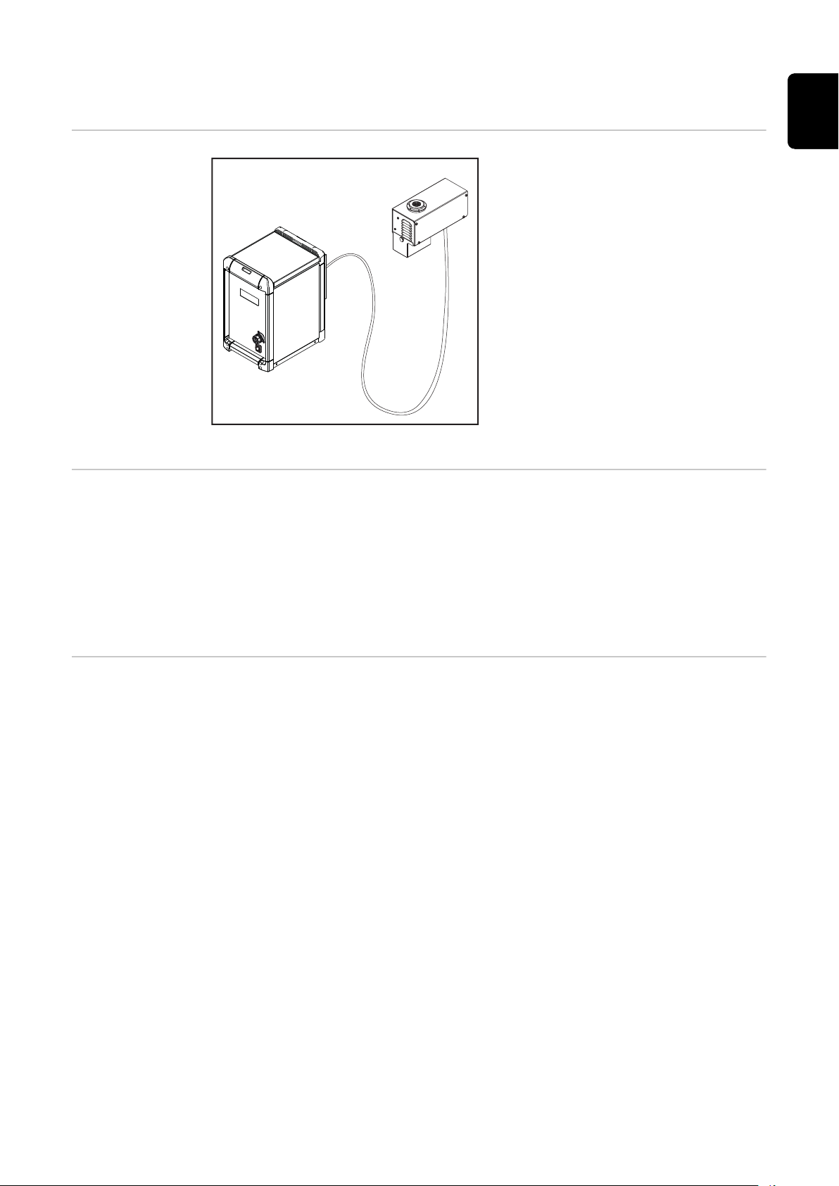
Device concept
Base unit with cleaning unit
Applications The cleaning device is intended for the cleaning of welding torches in automated
steel applications. The cleaning device is designed for use:
In the automotive and supply industry
-
In equipment engineering
-
In chemical plant construction
-
In mechanical engineering
-
In rail vehicle construction
-
In shipyards
-
The cleaning device consists of
a base unit – the Robacta TC 2000
-
ext. / Robacta TC 2000 ext. US
and
a cleaning unit – the Cleaning Unit
-
TC 2000 in various designs
The cleaning device is designed to
clean a variety of different welding
torch geometries. The components are
housed in a robust housing. The compact design permits installation in the
smallest of spaces.
The cleaning device is largely maintenance-free, since there are no parts
subject to mechanical stress.
Warning notices
on the device
The device has safety symbols and a rating plate fitted. These safety symbols and
the rating plate must not be removed or painted over. The symbols warn against
operating the equipment incorrectly, as this may result in serious injury and damage to property.
15
Page 16

WARNING! Risk of serious injuries due to:
The magnetic field of the cleaning aperture
-
Compressed air/parting agent mixture discharged from the
-
cleaning aperture
Flying debris (chips, etc.)
-
Moving mechanical parts
-
During maintenance and servicing, keep the device de-energized
and depressurized.
Do not use the functions described here until you have fully read
and understood the following documents:
These Operating Instructions
-
All system component Operating Instructions, especially the
-
safety rules
For indoor use only
Wear eye protection
16
Page 17

Prohibition for persons with pacemakers. Persons with pacemakers
must seek advice from their doctor before working with the device
or being in the immediate vicinity of the device
EN-US
17
Page 18
Functional principle
5
4,5
4
3,5
3
20 25 30 35 40
45 50
(2)
(1)
Operating principle
As soon as the cleaning device is connected to the grid, the 28 (page 28)
a)
lights up. The capacitors, which store the energy for the cleaning process, are
discharged and no outputs are actuated.
NOTE!
In order for the capacitors' charging process to begin, the following prerequisites must be met:
Base unit connected to the grid
▶
Base unit connected to the robot control
▶
Interconnecting hosepack of cleaning unit connected to the base unit
▶
The 'Quick Stop' signal must be set
▶
Before the capacitors are charged, the device temperature is checked. If it is
b)
within tolerance, the capacitors will be charged for the cleaning process.
If the operating temperature is exceeded, the overtemperature 28 (page
28) will light up. In this case, the charging process of the capacitors will
only take place after cooling down to the permissible operating temperature.
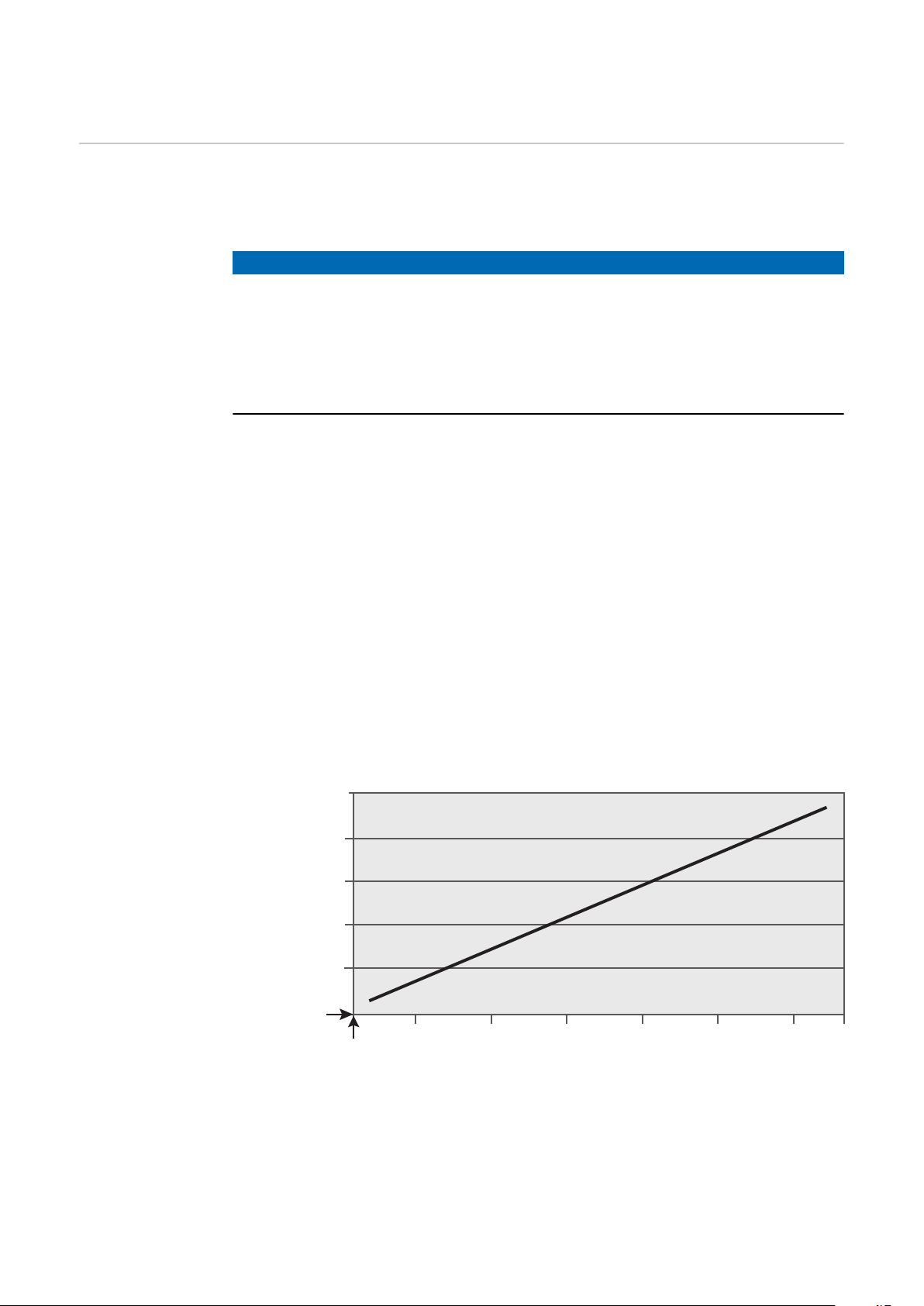
After 20 seconds of charging time, the 'Ready' signal will be output to the ro-
c)
bot control - the 29 indicator (page 29) on the device will flash. As soon as
the capacitors are fully charged, the indicator will light up permanently. Although after 20 seconds the maximum magnetic flux density is not yet available to the device, the cleaning process (discharge process) can be initiated
by means of the 'Cleaning Start' signal. For setup purposes, the cleaning process can be triggered manually by means of 29 (page 29) on the device.
After 50 seconds of charging time, the maximum magnetic flux density is
available for the cleaning process.
For the exact ratio of charging times to available magnetic flux density,
please see the diagram below.
Available magnetic flux density (Tesla)
Charging time (seconds)
18
Page 19

After the cleaning process has finished, the program sequence starts again
0 % 100 %
50 mm
1.97 in.
10 mm
0.39 in.
15 mm
0.59 in.
d)
with a check of the device temperature. If a cleaning process has finished incorrectly, the 'Error' signal will be output. The cleaning device once again initiates the charging process of the capacitors. If the cleaning readiness is
'Ready', another cleaning process can be carried out.
NOTE!
If the robot control deactivates the 'Quick Stop' signal during the program sequence, the cleaning device program sequence will be aborted immediately.
For safety reasons, the capacitors are discharged via the cleaning coil.
EN-US
Representation
of the magnetic
flux density
within the cleaning coil for
single-wire applications
Depending on the requirements, the insertion depth of the welding torch in the
cleaning coil can be used to regulate how strong an effect the magnetic flux
density should have on the individual areas of the welding torch.
NOTE!
For the operation of the cleaning device, use the insertion depth details for the
welding torch from the program sequence.
Insertion depth of
the torch body into
the cleaning coil
Cleaning coil
Diagram of available
magnetic flux density
19
Page 20

Representation
0 % 100 %
54 mm
2.13 in.
14 mm
0.55 in.
19 mm
0.75 in.
of the magnetic
flux density
within the cleaning coil for twin
applications
Depending on the requirements, the insertion depth of the welding torch in the
cleaning coil can be used to regulate how strong an effect the magnetic flux
density should have on the individual areas of the welding torch.
NOTE!
For the operation of the cleaning device, use the insertion depth details for the
welding torch from the program sequence.
Cleaning coil
Diagram of available
magnetic flux density
Insertion depth of
the torch body into
the cleaning coil
20
Page 21

Scope of Supply and Options
General The cleaning device may be operated in conjunction with various options. De-
pending on the area of application, various sequences in the work process can be
optimized as a result.
EN-US
Scope of Supply
Available Options
Base unit (available in various versions)
-
Standard I/O (X1) connecting plug without cable
-
Four screws for mounting the cleaning device on the work stand
-
Available options for the cleaning device
Cleaning unit (available in various versions)
-
Work stand for the base unit (available in various heights)
-
Work stand for the cleaning unit (available in various heights)
-
Wire cutter
-
Installation kit for parting agent atomizer
-
21
Page 22

Transport
Transport equipment
Transport Instructions on the
packaging
Transport the device using the following transport equipment:
On a pallet using a counterbalanced lift truck
-
On a pallet using a lift truck
-
Manually
-
WARNING!
Danger from devices and objects falling.
This can result in severe personal injury and damage to property.
When transporting the device by counterbalanced lift truck or lift truck, se-
▶
cure the device to prevent it from falling.
Do not turn, brake, or accelerate in a sudden, jerking manner.
▶
CAUTION!
Danger due to improper transport.
This can result in damage to property.
Follow the transport instructions on the device packaging.
▶
22
Page 23

Operating controls, connections
and mechanical components
23
Page 24

24
Page 25

Safety
Safety Please follow the safety rules below when using all the functions described in the
"Operating controls, connections, and mechanical components" chapter.
WARNING!
Danger from incorrect operation and work that is not carried out properly.
This can result in severe personal injury and damage to property.
All the work and functions described in this document must only be carried
▶
out by trained and qualified personnel.
Read and understand this document.
▶
Read and understand all the Operating Instructions for the system compon-
▶
ents, especially the safety rules.
EN-US
25
Page 26

Standard I/O (X1) Connecting Plug Configuration
for the Robot Control
General
Standard I/O
(X1) connecting
plug configuration
WARNING!
Danger from electrical current.
This can result in serious personal injury and damage to property.
The cleaning device must not be supplied with electrical power until the in-
▶
stallation has been completed.
NOTE!
To avoid any interference, keep the line length between the cleaning device and
the robot control as short as possible.
The standard I/O (X1) connecting plug for connecting the cleaning device to the
robot control is included in the scope of supply. Adjust the cable harness for the
robot control connection technology.
WARNING!
Danger due to unexpectedly activated cleaning device / unexpectedly activated
system components.
This can result in serious personal injury and damage to property.
Assign the signal input Quick Stop with either HIGH only, or
▶
Assign the signal input Quick Stop with LOW only.
▶
NOTE!
Depending on the requirements for the robot application, not all input and output signals (commands) need to be used.
The input and output signals that are underlined in the graphic below represent
the minimum level of commands to be applied.
26
Page 27

R
S
T
Not assigned
HIGH - Quick Stop
+24 V
Roboter
+24 V
+24 V
max. 20 mA
+24 V
max. 20 mA
+24 V
max. 20 mA
+24 V
+24 V
+24 V
GND
GND
GND
GND
GND
GND
LOW - Quick Stop
GND
HIGH - Cleaning Start
LOW - Cleaning Start
GND
GND
Supply Voltage
Ready
Supply Voltage
Fluid Level Control
Supply Voltage
Cleaning Error
CT atcaboR
Spray In
GND
Wire Cutter
EN-US
Standard I/O (X1) connecting plug configuration
27
Page 28

Operating controls, connections and mechanical
(1)
(2)
(3) (4)
(5)
components
General All functions of the cleaning device are activated via the robot control. For setup
operation, the cleaning process can be triggered manually on the base unit housing.
NOTE!
Individual images may differ slightly from your device.
However, the function of the operating elements and connections is identical.
Control panel
No.
Function
(1) Mains voltage indication
Lights up when the device is being supplied with mains voltage
NOTE!
If the capacitors have been charged in the device, they usually discharge automatically as soon as the device is disconnected from the grid.
The discharge time is usually around 1 second.
In the event of an error, the capacitors may not be discharged. In this case, it is
essential to follow the instructions in the section What to Do in the Event of an
Error on page 57.
(2) Overtemperature indication
Lights up when the device heats up excessively
28
Page 29

NOTE!
(1)
(2)
After this indication lights up, one more cleaning process can be carried out.
The device will not charge itself for the next cleaning process until it has cooled
down to the operating temperature.
(3) Fill level indication
No function, always lit
(4) Discharge button
If the button is pressed briefly, the cleaning device will carry out the fol-
lowing functions:
Cleaning process is triggered
1.
If the button is pressed and held down, the cleaning device will carry out
the following functions in sequence:
Cleaning process is triggered
1.
Wire cutter is activated (if present)
2.
Compressed air/parting agent mixture is sprayed out of the cleaning
3.
aperture
NOTE!
EN-US
Connections and
mechanical components of the
base unit
Prerequisite for the cleaning device to perform the above function:
The signal Quick Stop is set, capacitors are thus charged
▶
(5) Ready to clean indication
Lights up when the device is ready to clean
WARNING!
Danger from electrical current.
This can result in serious personal injury and damage to property.
Once the ready to clean indication (5) lights up, do not disconnect the inter-
▶
connecting hosepack from the base unit.
Before disconnecting the interconnecting hosepack, disconnect the power
▶
supply and the compressed air supply to the base unit.
(1) Standard I/O (X1) connection
socket
(2) Mains cable connection socket
Device front
29
Page 30

(3)
(4)
Device rear
(5)
(6)
(1)
(2)
(3) Cleaning unit connection sock-
et
For connecting the cleaning
unit connection cable
(4) Compressed air connection
socket
For supplying the cleaning
device with compressed air
(5) Work stand (option)
(6) Collecting container for weld-
ing residues
Connections and
mechanical components of the
cleaning unit
Optional work stand
Top of the cleaning unit
(1) Cleaning aperture with internal
parting-agent injection nozzles
and brush seal
For cleaning the gas nozzle
-
and the interior of the
welding torch
For wetting the gas nozzle
-
and the interior of the
welding torch with parting
agent
(2) Collecting container for weld-
ing residues
30
Page 31

NOTE!
(4)(5)
(3)
The cleaning aperture of the standard cleaning unit (Cleaning Unit TC 2000) is
equipped with a brush seal at the factory.
This cleaning unit may only be operated if the brush seal is installed. Brush seals
must not be removed.
(3) Interconnecting hosepack
For connecting to the base unit
WARNING!
Danger from electrical current.
This can result in serious personal injury and damage to property.
Once the ready to clean indication
▶
lights up, do not disconnect the interconnecting hosepack from the
base unit.
Before disconnecting the intercon-
▶
necting hosepack, disconnect the
Underside of the cleaning unit
power supply and the compressed
air supply to the base unit.
EN-US
(4) Parting agent atomizer connection socket
For connecting to the 'Robacta Reamer' parting agent container
(5) Wire cutter connection socket
For electrically controlling the wire cutter
31
Page 32

32
Page 33

Installation and Startup
33
Page 34

34
Page 35

Safety
Safety Please follow the safety rules below during all the tasks described in the "Install-
ation and commissioning" chapter.
WARNING!
Danger from incorrect operation and work that is not carried out properly.
This can result in serious personal injury and damage to property.
All the work and functions described in this document must only be carried
▶
out by a trained Fronius service technician.
Read and understand this document in full.
▶
Read and understand all safety rules and user documentation for this equip-
▶
ment and all system components.
WARNING!
Danger due to machines starting automatically.
This can result in serious personal injury and damage to property.
In addition to these Operating Instructions, observe the safety rules of the
▶
robot manufacturer and welding system manufacturer.
Ensure that all protective measures have been taken in the robot's operating
▶
area and remain in effect while you are in this area.
EN-US
WARNING!
Danger from electric shock and mechanically moving parts.
This can result in serious personal injury and damage to property.
Before working on the cleaning device or the associated system components,
▶
disconnect the customer's compressed air and voltage supply from the
cleaning device and the associated system components.
Make sure that the customer's compressed air and power supply remain dis-
▶
connected from the cleaning device and the associated system components
until all work has been completed.
WARNING!
If the cleaning device is being supplied with voltage and/or compressed air,
there is a risk of serious injury due to:
the magnetic field of the cleaning opening,
flying parts (chips, etc.),
compressed air/parting agent mixture escaping from the cleaning opening,
activated wire cutter.
This can result in serious personal injury and damage to property.
If work is required on the cleaning device while the cleaning device is being supplied with voltage and/or compressed air, take the following safety measures:
Keep all ferromagnetic parts away from the device (e.g., tools).
▶
Keep your body, especially hands, face, and hair, as well as objects and all
▶
items of clothing, away from the cleaning aperture and the wire cutter.
Wear hearing protection.
▶
Wear protective goggles with side protection.
▶
35
Page 36

Before installation
Operating personnel, maintenance personnel
Setup regulations
WARNING!
Danger due to machines starting automatically.
This can result in severe personal injury and damage to property.
The device must only ever be operated/maintained by one person.
▶
Ensure that there is only one person in the device’s operating area while it is
▶
being worked on.
The device has been tested according to protection class IP 21. This means:
Protection against solid foreign bodies larger than Ø 12.5 mm (0.49 inches)
-
Protection against dripping water
-
The device must not be set up and operated outdoors. The installed electrical
components must be protected against direct exposure to moisture.
NOTE!
Install the device at a minimum distance of 1 m (40 inches) away from IT equipment and control lines, as well as from the welding process.
NOTE!
Specifications
for the compressed air supply
Install the device with an all-round clearance of at least 0.5 m (19.69 inches) to
walls, neighboring devices, or other objects.
NOTE!
Set up the device in such a way that welding spatter cannot hit the cleaning
device.
To ensure the proper functioning of the cleaning device, fulfill the following specifications for the compressed air supply:
Set up a compressed air supply using the pressure relief valve and com-
-
pressed air filter
Guarantee the compressed air quality in accordance with ISO 8573-1:2001,
-
class 7 4 3, instrument air
-
Solid particle concentration £ 10 mg/m
Pressure dew point steam £ + 3 °C
-
-
Oil concentration £ 1 mg/m
3
3
36
Page 37

Mains connection
CAUTION!
Danger due inadequately dimensioned electrical installations.
This can lead to serious damage
The grid lead and its fuse protection should be designed to suit the existing
▶
power supply.
The technical data on the rating plate should be followed.
CAUTION!
Danger due to incorrect mains voltage.
Serious damage may result.
If the mains voltage is outside the tolerances specified in the technical data,
▶
do not connect the device to the grid.
The cleaning device is designed for the mains voltage listed on the rating plate.
The fuse protection required for the grid lead may be found in the "Technical
data" section. If mains cables or mains plugs are not included with your version
of the appliance, attach the appropriate mains cable or mains plug in accordance
with your country's standards.
EN-US
37
Page 38
Setting Up and Connecting the Cleaning Device
Assembly note
Screwing the
cleaning unit and
work stand to
the mounting
surface (foundation)
NOTE!
Before the definitive installation of the base unit and cleaning unit, make sure
that the cleaning unit interconnecting hosepack is long enough for the planned
installation positions.
After the installation of the devices, the interconnecting hosepack must rest on
the ground without any tensile stress and must not be suspended in the air.
WARNING!
Danger from welding residues being thrown out of the cleaning aperture of the
cleaning unit.
This can result in serious personal injury and damage to property.
Only use the cleaning unit with the supplied collecting container for welding
▶
residues.
WARNING!
Danger from machines toppling over or falling.
This can result in serious personal injury and damage to property.
Depending on the mounting surface (foundation), different mounting materi-
▶
als may be required for connecting the work stand to the surface.
The mounting materials required for connecting the work stand to the
▶
mounting surface are not supplied with the work stand. The screws that are
supplied with the work stand are not suitable for screwing the work stand to
the mounting surface. The installer is responsible for selecting the proper
mounting materials.
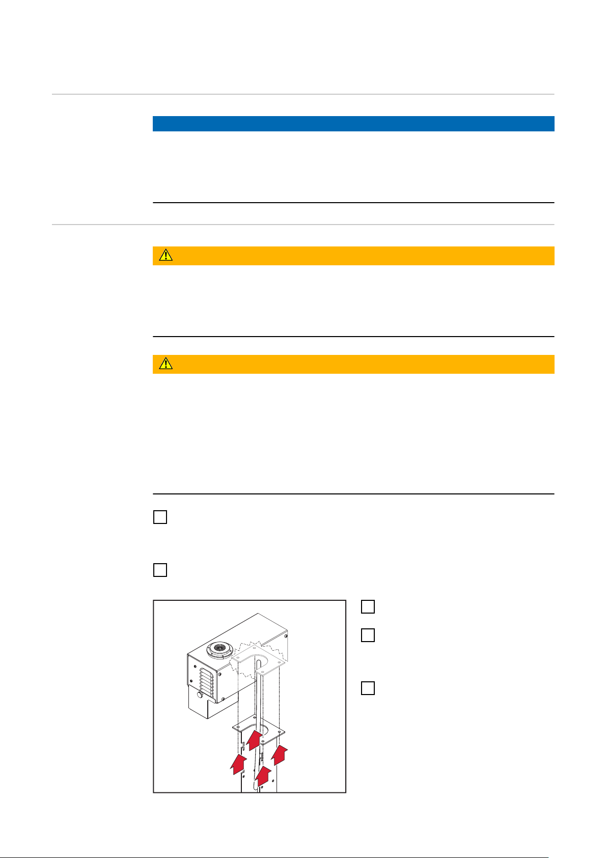
Position the work stand (available as an option) on a level, solid, and vibra-
1
tion-free surface
Position the work stand so that the robot's approach route to the clean-
-
ing unit on the work stand is as short as possible
Tightly screw the work stand to the mounting surface using the selected
2
mounting materials
Position the cleaning unit on the
3
work stand
Attach the cleaning unit to the
4
work stand using lock washers and
screws – lock washers and screws
are supplied with the work stand
Clip the collecting container for
5
the welding residues onto the
cleaning unit and fasten it with the
knurled-head screw
38
Page 39
Screwing the
base unit and
work stand to
the surface
(foundation)
WARNING!
Danger from machines toppling over or falling.
This can result in serious personal injury and damage to property.
Only attach the base unit to the foundation with the work stand provided for
▶
that purpose.
Depending on the surface, different mounting materials may be required for
▶
connecting the work stand to the surface.
The mounting materials required for connecting the work stand to the
▶
mounting surface are not supplied with the work stand. The screws that are
supplied with the work stand are not suitable for screwing the work stand to
the mounting surface. The installer is responsible for selecting the proper
mounting materials.
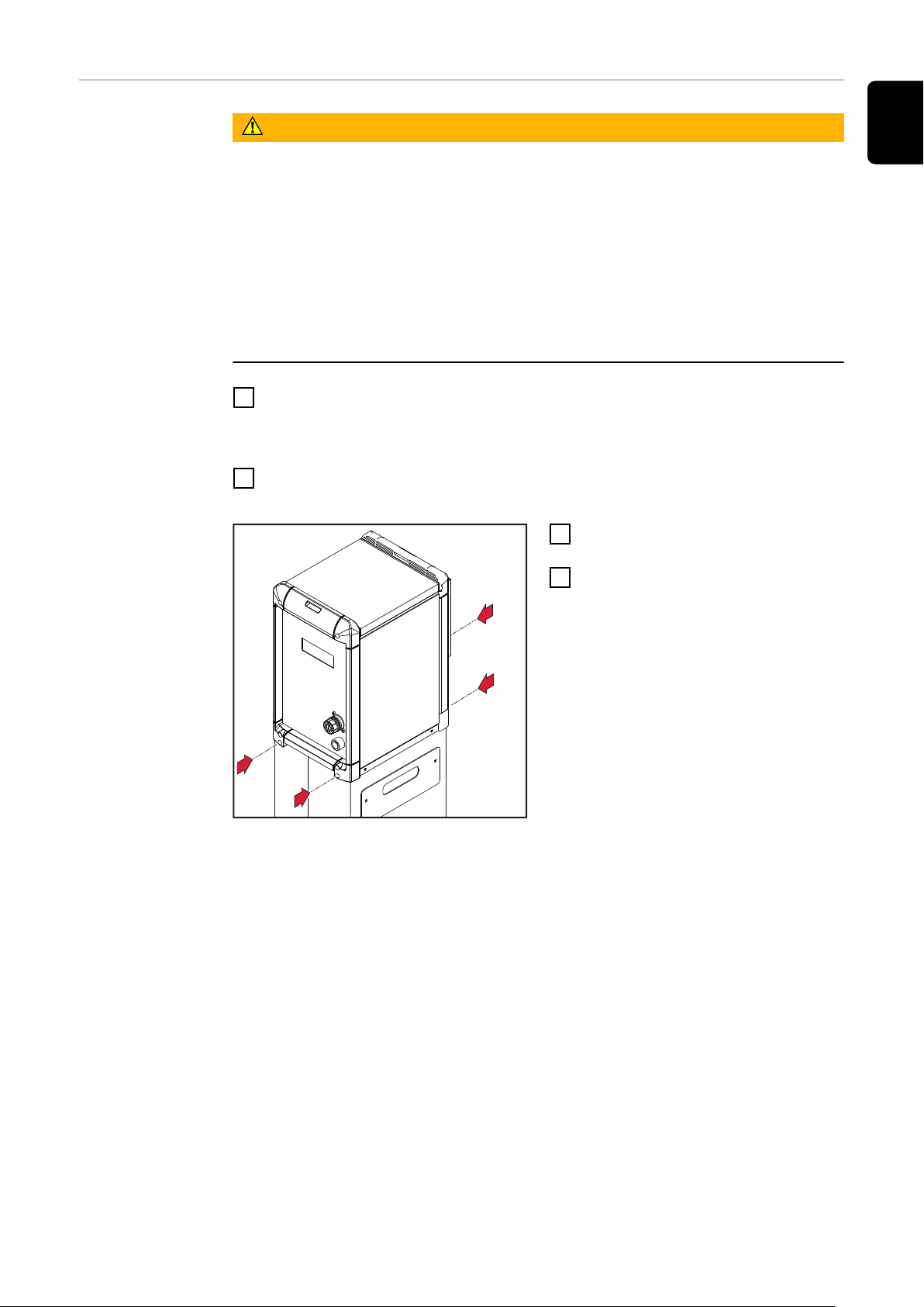
Position the work stand (available as an option) on a level, solid, and vibra-
1
tion-free surface
Position the work stand in such a way that the interconnecting hosepack
-
of the cleaning unit can be connected to the base unit
Tightly screw the work stand to the mounting surface using the selected
2
mounting materials
Position the base unit on the work
3
stand
Attach the base unit to the work
4
stand with four screws – use the
screws supplied with the base unit
EN-US
39
Page 40
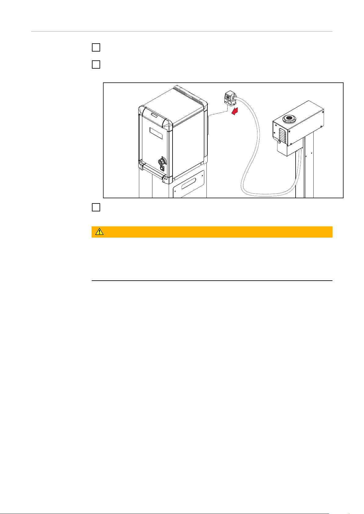
Connecting the
1
cleaning unit to
the base unit
Remove the cover from the cleaning unit connection socket on the rear of
1
the base unit
Insert the connecting plug of the interconnecting hosepack into the base
2
unit
Tighten the screws on the connecting plug of the interconnecting hosepack
3
to secure it in the cleaning unit connection socket
WARNING!
Danger from electrical current.
This can result in serious personal injury and damage to property.
If the interconnecting hosepack needs to be disconnected after commission-
▶
ing the base unit, disconnect the voltage supply and the compressed air supply before disconnecting the hosepack.
40
Page 41
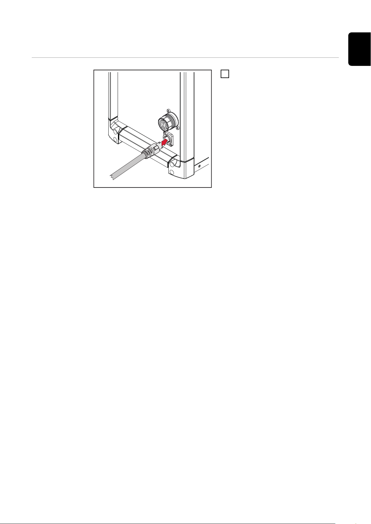
Connecting the Mains Cable
1
EN-US
Connecting the
mains cable
To connect the mains cable:
1
Plug in the mains cable
-
Turn the mains cable 45° to
-
the right until it audibly locks
into place
41
Page 42

Installing the wire cutter
Installing the
wire cutter on
the cleaning
device
NOTE!
Wire cutters for conventional applications (one wire electrode) and for twin applications (two wire electrodes) should be installed in the same manner – as described below.
NOTE!
The spacers, lock washers and screws for installing the wire cutter are supplied
with the wire cutter.
1
Maximum Wire
Diameter
Operating Principle of the Electrically Controlled Wire Cutter
Connect the wire cutter connection cable to the wire cutter connection sock-
2
et on the cleaning unit
Connect the wire cutter's compressed air supply
3
For conventional applications (one wire electrode), wire electrodes with a diameter of up to 1.6 mm (0.063 in.) can be cut with the appropriate wire cutter.
For twin applications (two wire electrodes), two wire electrodes with a diameter
of up to 1.6 mm (0.063 in.) can be cut simultaneously with the appropriate wire
cutter.
The opening and closing of the electrically controlled wire cutter is triggered by
an active signal from the robot control.
42
Page 43

Connecting the Cleaning Unit to the ‘Robacta
2
3
4
1
5
6
(1)
Reamer’ Parting Agent Container
Connecting the
cleaning unit to
the 'Robacta
Reamer' parting
agent container
NOTE!
Only use the 'Robacta Reamer' parting agent provided by the manufacturer.
Its composition is specifically tailored for use with the cleaning device. Correct
operation is not ensured when other products are used.
1
EN-US
Connect the parting agent hose
2
from the parting agent container
to the parting agent atomizer connection socket (1) on the underside
of the cleaning unit
NOTE!
The parting agent injection time must
be set via the robot control.
The selected injection time cannot be
less than 0.5 seconds.
An injection time of ~ 0.7 seconds is
recommended. Depending on the size
of the gas nozzle, the necessary injection time may vary.
Underside of the cleaning unit
43
Page 44

Start up the Cleaning Device
General
Requirements
for Commissioning
NOTE!
If wetting agent has not been applied to the inside of the welding torch, this may
lead to the permanent contamination of the welding torch when welding begins.
Always wet the inside of the welding torch with the manufacturer's 'Robacta
Reamer' parting agent before starting an automatic application.
To achieve optimum cleaning results, observe the following points:
Always wet the inside of the welding torch with parting agent
-
Adhere to the specified cleaning procedures
-
Adhere to the specified cleaning positions
-
Blow out the welding torch with compressed air during cleaning (but not
-
while parting agent is being injected into the inside of the welding torch)
NOTE!
Individual small spatters are not removed by the cleaning device.
Small welding spatters do not, however, affect the welding process.
The following requirements must be met in order to commission the cleaning
device:
Base unit screwed tightly to the surface
-
Cleaning unit screwed tightly to the surface
-
Interconnecting hosepack of cleaning unit connected to the base unit
-
Base unit connected to the grid
-
Base unit supplied with compressed air
-
Base unit connected to the robot control
-
Only if present/used
‘Robacta Reamer’ parting agent container connected to the cleaning unit
-
Wire cutter installed and supplied with compressed air
-
44
Page 45

Cleaning Program Sequence for Single Wire Ap-
60 mm
( 2.36 in.)
50 mm
( 1.97 in.)
(1)
plications
Program Sequence with
Parting Agent
Atomizer –
Overview
Cleaning the Gas
Nozzle Tip and
Nozzle Fitting –
Detailed Description
Welding
1.
Clean the gas nozzle tip and nozzle fitting
2.
Inject parting agent
3.
Welding
4.
NOTE!
During the cleaning process, blow out the welding torch with compressed air via
the hosepack.
Contamination and surplus parting agent will be removed.
NOTE!
Make sure that the gas nozzle does not
touch the housing parts of the cleaning aperture at any time.
EN-US
Injecting Parting
Agent – Detailed
Description
Position the welding torch approx.
1
50 mm (1.97 in.) above the cleaning aperture and centrically with
respect to the middle of the cleaning aperture
NOTE!
If the brush seal (1) is installed, pay
attention to the changed reference
point when positioning the welding
torch.
Move the welding torch vertically to the cleaning position
2
See graphic
-
Trigger the cleaning process and leave the welding torch in the cleaning posi-
3
tion for approximately 1 second
The even application of a parting agent has the following advantages:
Reduced adhesion of welding spatter
-
New contamination is prevented
-
NOTE!
If the brush seal (1) is installed, pay attention to the changed reference point
when positioning the welding torch.
45
Page 46

NOTE!
75 mm
( 2.95 in.)
65 mm
( 2.56 in.)
(1)
Make sure that the gas nozzle does not touch the housing parts of the cleaning
aperture at any time.
Move the welding torch to the in-
1
jection position
See graphic
-
NOTE!
During the injection process, do not
blow out compressed air through the
welding torch.
Inject parting agent into the weld-
2
ing torch for approximately
0.7 seconds
Move the welding torch to the starting position above the cleaning aperture –
3
approximately 50 mm (1.97 in.) above the cleaning aperture and centrically
with respect to the middle of the cleaning aperture
The cleaning process is completed and the welding torch is ready for use
-
again
Make sure that not too much parting agent has collected at the gas nozzle
4
(no formation of drops). If this is the case:
reduce the injection time, or
-
after the cleaning process, blow out the welding torch with compressed
-
air through the hosepack
46
Page 47

Cleaning Program Sequence
with Parting
Agent Atomizer
Start
Program “Welding torch
cleaning”
Move to position A
Move to position B
Set 1
Wait 0.5 seconds
Set 2
Wait 0.5 seconds
Set 1/Reset 1
Compressed air gas purging with welding
torch
Set 2/Reset 2
Signal “Cleaning start”
Set 3/Reset 3
Signal “Spray in parting agent”
EN-US
Reset 1
Reset 2
Move to position C
Set 3
Wait 0.7 seconds
Reset 3
Move to position A
End
47
Page 48

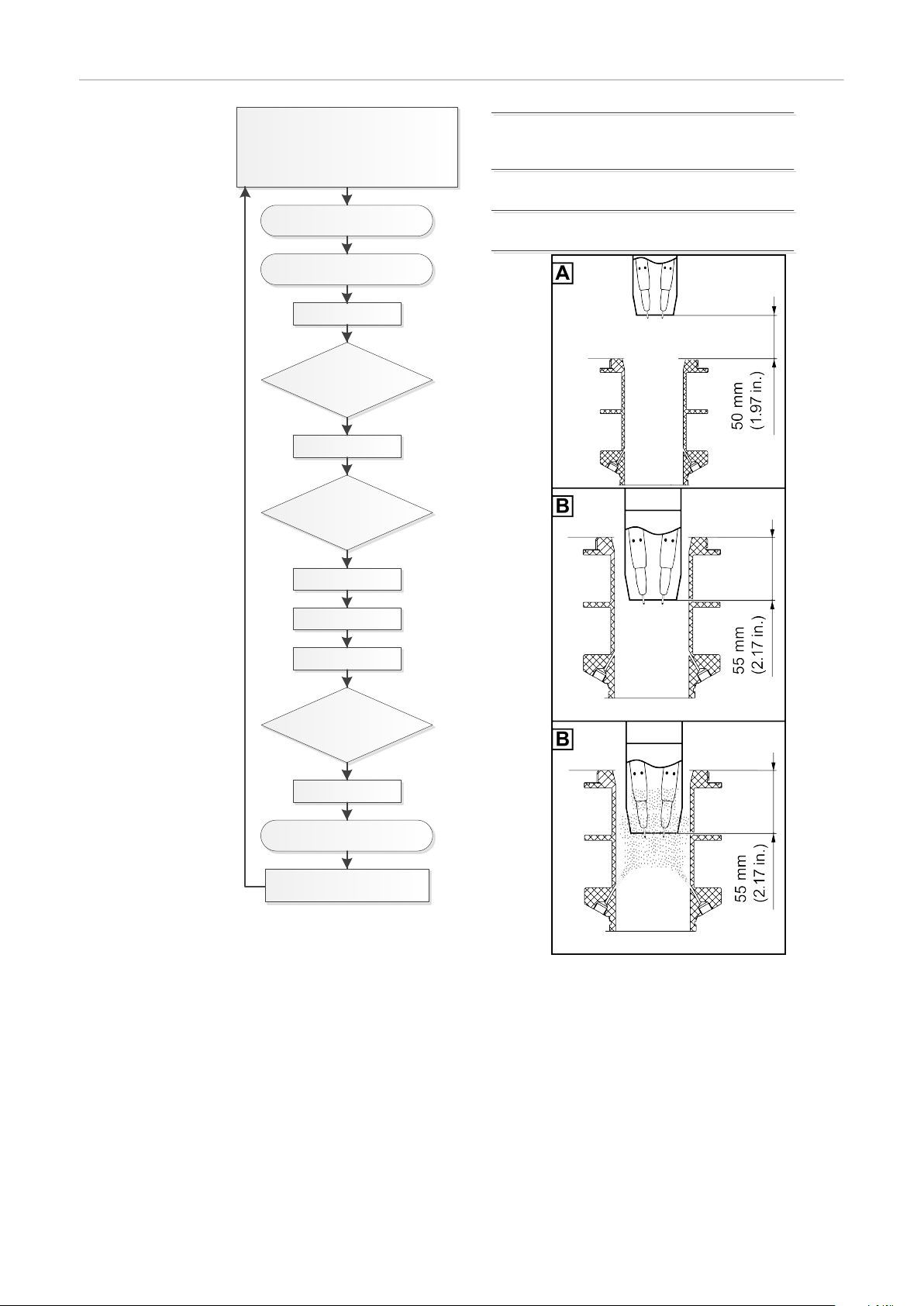
Cleaning Program Sequence for Twin Applica-
55 mm
(2.17 in.)
tions
Program Sequence with
Parting Agent
Atomizer –
Overview
Cleaning the gas
nozzle tip and
nozzle fitting –
detailed description
Welding
1.
Clean the gas nozzle tip and nozzle fitting
2.
Inject parting agent
3.
Welding
4.
NOTE!
During the cleaning process, blow out the welding torch with compressed air via
the hosepack. Contamination and surplus parting agent will be removed.
NOTE!
Make sure that the gas nozzle does not
touch the housing parts of the cleaning aperture at any time.
Position the welding torch approx.
1
50 mm (1.97 in.) above the cleaning aperture and centrically with
respect to the middle of the cleaning aperture
Move the welding torch vertically
2
to the cleaning/injection position
See graphic
-
Trigger the cleaning process and
3
wait for approximately 1 second
Injecting parting
agent – detailed
description
48
The even application of a parting agent has the following advantages:
Reduced adhesion of welding spatter
-
New contamination is prevented
-
NOTE!
Make sure that the gas nozzle does not touch the housing parts of the cleaning
aperture at any time.
Page 49

55 mm
(2.17 in.)
Maintain the cleaning position/
1
injection position
See graphic
-
NOTE!
During the injection process, do not
blow out compressed air through the
welding torch.
Inject parting agent into the weld-
2
ing torch for approximately
0.7 seconds
Move the welding torch to the starting position above the cleaning aperture –
3
approximately 50 mm (1.97 in.) above the cleaning aperture and centrically
with respect to the middle of the cleaning aperture
The cleaning process is completed and the welding torch is ready for use
-
again
Make sure that not too much parting agent has collected at the gas nozzle
4
(no formation of drops). If this is the case:
reduce the injection time, or
-
after the cleaning process, blow out the welding torch with compressed
-
air through the hosepack
EN-US
49
Page 50
Cleaning Program Sequence
with Parting
Agent Atomizer
Start
Program “Welding torch
cleaning”
Move to position A
Move to position B
Set 1
Wait 0.5 seconds
Set 2
Wait 0.5 seconds
Set 1/Reset 1
Compressed air gas purging with welding
torch
Set 2/Reset 2
Signal “Cleaning start”
Set 3/Reset 3
Signal “Spray in parting agent”
Reset 1
Reset 2
Set 3
Wait 0.7 seconds
Reset 3
Move to position A
End
50
Page 51

Troubleshooting, Maintenance, and
Disposal
51
Page 52

52
Page 53

Safety
Safety Please follow the safety rules below during all the tasks described in the
"Troubleshooting, maintenance, and disposal" chapter.
WARNING!
Danger from incorrect operation and work that is not carried out properly.
This can result in serious personal injury and damage to property.
All the work and functions described in this document must only be carried
▶
out by a trained Fronius service technician.
Read and understand this document in full.
▶
Read and understand all safety rules and user documentation for this equip-
▶
ment and all system components.
WARNING!
Danger due to machines starting automatically.
This can result in serious personal injury and damage to property.
In addition to these Operating Instructions, observe the safety rules of the
▶
robot manufacturer and welding system manufacturer.
Ensure that all protective measures have been taken in the robot's operating
▶
area and remain in effect while you are in this area.
EN-US
WARNING!
Danger from electric shock and mechanically moving parts.
This can result in serious personal injury and damage to property.
Before working on the cleaning device or the associated system components,
▶
disconnect the customer's compressed air and voltage supply from the
cleaning device and the associated system components.
Make sure that the customer's compressed air and power supply remain dis-
▶
connected from the cleaning device and the associated system components
until all work has been completed.
WARNING!
If the cleaning device is being supplied with voltage and/or compressed air,
there is a risk of serious injury due to:
the magnetic field of the cleaning opening,
flying parts (chips, etc.),
compressed air/parting agent mixture escaping from the cleaning opening,
activated wire cutter.
This can result in serious personal injury and damage to property.
If work is required on the cleaning device while the cleaning device is being supplied with voltage and/or compressed air, take the following safety measures:
Keep all ferromagnetic parts away from the device (e.g., tools).
▶
Keep your body, especially hands, face, and hair, as well as objects and all
▶
items of clothing, away from the cleaning aperture and the wire cutter.
Wear hearing protection.
▶
Wear protective goggles with side protection.
▶
53
Page 54

WARNING!
Danger due to insufficient ground conductor connection.
This can result in serious personal injury and damage to property.
The housing screws provide an adequate ground conductor connection for
▶
grounding the housing and should not under any circumstances be replaced
by other screws that do not provide a reliable ground conductor connection.
54
Page 55

Troubleshooting
Troubleshooting Make a note of the serial number and configuration of the device, and provide
the service team with a detailed error description if:
Errors occur that are not covered in this document
-
The troubleshooting measures provided in this document are unsuccessful
-
Grid voltage indication does not light up
Grid lead connected
EN-US
Cause:
Remedy:
“Ready to clean” signal is not output to the robot control
Grid voltage indication lights up
Cause:
Remedy:
Cause:
Remedy:
Cause:
Remedy:
“Ready to clean” signal is not output to the robot control
Grid voltage indication lights up, overtemperature indication lights up
Cause:
Remedy:
Grid lead defective
Check grid lead
Quick Stop is active (HI - Quick Stop = LO or LO - Quick Stop = HI)
Deactivate Quick Stop (HI - Quick Stop = HI or LO - Quick Stop = LO)
Supply to the standard I/O (X1) connection socket defective
Depending on the connection, check the assignment of inputs B and
H or C and H, as well as D or G
Temperature sensor of cleaning coil defective
Contact service team – cleaning coil needs replacing
Cleaning device has overheated
Allow cleaning device to cool down. As soon as the permissible oper-
ating temperature has been reached, a new capacitor charging process will take place. The cleaning device will then be ready to clean
again
55
Page 56

Parting agent is not injected
‘Robacta Reamer’ parting agent container is full
Cause:
Remedy:
Cause:
Remedy:
Cause:
Remedy:
Cause:
Remedy:
Cause:
Remedy:
Cause:
Remedy:
Parting agent is not injected
Cause:
Remedy:
Injection quantity too low
Set injection quantity (injection time)
Intake filter in ‘Robacta Reamer’ parting agent container dirty
Blow out the intake filter in the ‘Robacta Reamer’ parting agent con-
tainer from the inside out with compressed air using the intake hose
(see section Clean the intake filter in the parting agent container
starting on page 58)
Compressed air supply interrupted
Set up the compressed air supply
Compressed air supply line defective or dirty
Clean compressed air supply line and replace if necessary
Vacuum pump defective
Contact service team (vacuum pump needs replacing)
Solenoid valve defective
Contact service team (solenoid valve needs replacing)
‘Robacta Reamer’ parting agent container is empty
Fill with parting agent
Cause:
Remedy:
Pores in the weld seam
Cause:
Remedy:
Cause:
Remedy:
Error is issued to robot. Overtemperature indication and fill level indication
flash at the same time; cleaning does not take place
Cause:
Remedy:
Cause:
Remedy:
Interconnecting hosepack damaged
Inform service team
Too much parting agent in the inside of the welding torch
Remove residues of parting agent by blowing out the inside of the
welding torch. Ensure supply of compressed air
Too much parting agent in the inside of the welding torch
Reduce parting agent injection quantity (shorten duty cycle of pump
for parting agent)
Quick Stop is active (HI - Quick Stop = LO or LO - Quick Stop = HI)
Deactivate Quick Stop (HI - Quick Stop = HI or LO - Quick Stop = LO)
The cleaning device has detected an error
Disconnect the cleaning device from the grid and reconnect after ap-
proximately 1 minute
If this does not lead to any improvement, contact the service team
and follow the instructions in the next chapter What to Do in the
Event of an Error on page 57
56
Page 57

What to Do in the Event of an Error
(1) (2)
(1)
(1)
(1)
(1)
(1)(1)
EN-US
What to Do in
the Event of an
Error
WARNING!
Danger of serious damage to property
and personal injury from electric
shock.
The cleaning device has detected a
serious error if:
The overtemperature indication (1)
▶
and fill level indication (2) flash
simultaneously
The Quick-Stop signal is not active
▶
In this case, the cleaning unit interconnecting hosepack must not be disconnected from the base unit until the following safety measures have been
taken.
Safety measures:
Ensure that the cleaning device is
1
disconnected from the power and
compressed air supply
Looking from the front, remove the
2
left side panel from the base unit
Make sure that the six capacitors
3
(1) are discharged
Replace the side panel
4
The cleaning unit interconnect-
-
ing hosepack can now be disconnected from the base unit
Side view of base unit with open side panel
57
Page 58

Service, maintenance and disposal
Before Every
Start-up
Daily
Weekly
Check the fill level in the ‘Robacta Reamer’ parting agent container and top
1
up if necessary
NOTE!
Only clean the devices with cleaning products that are free of solvents.
Remove any deposited parting agent and contamination from the outside of
1
the base unit and cleaning unit.
Empty the cleaning unit’s welding residue collecting container
1
Clean the inside of the cleaning unit’s cleaning aperture
2
Check the ‘Robacta Reamer’ parting agent container for contamination and
3
clean if necessary
Blow out the intake filter in the ‘Robacta Reamer’ parting agent container
4
from the inside out with compressed air using the intake hose (see section
Clean the intake filter in the parting agent container starting on page 58)
If present, check the condition of the brush seal above the cleaning aperture.
5
If the brush seal is worn out, replace it
Every Six
Months
Every 12 Months
Clean the intake
filter in the parting agent container
NOTE!
Do not blow electronic parts clean from a short distance away.
Open the base unit and cleaning unit and blow clean with dry and reduced
1
compressed air
Have a Fronius service technician perform a safety inspection on the cleaning
1
device
NOTE!
Only use the ‘Robacta Reamer’ parting agent provided by the manufacturer.
Its composition is specifically tailored for use with the Robacta TC. Correct operation is not ensured when other products are used.
58
Page 59

1
2
1
1
3
2
4
1
2
2
EN-US
3
Disposal Disposal must only be carried out in accordance with the section of the same
name in the "Safety rules" chapter.
59
Page 60

60
Page 61

Technical data
61
Page 62

62
Page 63

Technical data
EN-US
General
Robacta TC
2000 ext.
CAUTION!
Danger due to insufficiently dimensioned electrical installations.
Serious damage may result.
Select the grid lead and fuse protection to suit the device being used.
▶
The technical data on the rating plate applies.
Mains voltage 230 V
Mains voltage tolerance -10%/+10%
Grid frequency 50/60 Hz
Nominal output 180 W
Mains fuse, slow-blow 10 A
Compressed air supply 6 bar
86.99 psi
Minimum cleaning interval From 20 s
Protection class IP 21
Dimensions l/w/h 360/250/422 mm
14.17/9.84/16.61 in.
Robacta TC
2000 ext. US
Weight 18.75 kg
41.35 Ib.
EMC device class A
Marks of conformity CE, CSA
Mains voltage 110 V
Mains voltage tolerance -5%/+5%
Grid frequency 50/60 Hz
Nominal output 180 W
Mains fuse, slow-blow 10 A
Compressed air supply 6 bar
86.99 psi
Minimum cleaning interval From 20 s
Protection class IP 21
Dimensions l/w/h 360/250/422 mm
14.17/9.84/16.61 in.
Weight 18.35 kg
40.45 Ib.
EMC device class A
Marks of conformity CE, CSA
63
Page 64

Cleaning Unit TC
2000
EMC device class A
Dimensions l/w/h (without interconnecting hosepack
and collecting container for welding residues)
Weight 8.1 kg
340/145/300 mm
13.39/5.71/8.66 in.
17.86 lb.
Cleaning Unit TC
2000 LH
Cleaning Unit TC
2000 Twin
Cleaning Unit TC
2000 Twin
EMC device class A
Dimensions l/w/h (without interconnecting hosepack
and collecting container for welding residues)
Weight 9.5 kg
EMC device class A
Dimensions l/w/h (without interconnecting hosepack
and collecting container for welding residues)
Weight 9.6 kg
EMC device class A
Dimensions l/w/h (without interconnecting hosepack
and collecting container for welding residues)
340/145/300 mm
13.39/5.71/8.66 in.
20.94 lb.
340/145/300 mm
13.39/5.71/8.66 in.
21.16 lb.
340/145/300 mm
13.39/5.71/8.66 in.
Weight 8.4 kg
18.52 lb.
64
Page 65

EN-US
65
Page 66

66
Page 67

EN-US
67
Page 68

 Loading...