

Operating
Instructions
Robacta Reamer V Easy
Robacta Reamer V Easy Han6P J
Robacta Reamer V
Operating Instructions
EN
42,0426,0094,EN 042-01022023


Contents
Safety rules 6
Explanation of safety notices 6
General 6
Proper use 7
Environmental conditions 7
Obligations of the operator 7
Obligations of personnel 7
Specific hazards 7
Protecting yourself and others 8
EMC Device Classifications 8
EMC measures 9
EMF measures 9
Safety measures at the installation location and during transport 9
Safety measures in normal operation 10
Commissioning, maintenance and repair 10
Safety inspection 10
Disposal 11
Safety symbols 11
Copyright 11
General 13
General 15
Principle 15
Illustration of the various types 15
Device concept - Robacta Reamer V Easy, Robacta Reamer V 15
Device concept - Robacta Reamer V Easy Han6P J 15
Applications 16
Warning notices on the cleaning device 16
Transport 19
Transport devices 19
Transport notices on the packaging 19
Robacta Reamer V Easy scope of supply and options 20
Robacta Reamer V Easy scope of supply 20
Robacta Reamer V Easy options 20
Robacta Reamer V Easy Han6P J scope of supply, options and required components 21
Robacta Reamer V Easy Han6P J scope of supply 21
Robacta Reamer V Easy Han6P J required components 21
Robacta Reamer V Easy Han6P J options 21
Robacta Reamer V scope of supply and options 23
Robacta Reamer V scope of supply 23
Robacta Reamer V options 23
EN
Controls, connections and mechanical components 25
Safety 27
Safety 27
Robacta Reamer V Easy, Robacta Reamer V Easy Han6P J control elements, connections and
mechanical components
Robacta Reamer V Easy, Robacta Reamer V Easy Han6P J control elements, connections
and mechanical components
Robacta Reamer V control elements, connections and mechanical components 30
Robacta Reamer V control elements, connections and mechanical components 30
Standard I/O connecting plug (X1) pin assignment for robot control (Robacta Reamer V) 32
General 32
Robacta Reamer V pin assignment on standard I/O connecting plug (X1) 32
Harting Han6P connecting plug pin assignment (X1) for robot control (Robacta Reamer V
Easy, Robacta Reamer V Easy Han6P J)
General 33
Harting Han6P connecting plug pin assignment (X1) 33
28
28
33
3

Installation and commissioning 35
Safety 37
Safety 37
Ensuring that the cleaning device is depressurised 38
Before commissioning 39
Proper use 39
Operators, maintenance personnel 39
Setup regulations 39
Compressed air supply specifications 39
Measures for the safe operation of the device with untrained personnel 40
Screwing the Robacta Reamer V Easy, Robacta Reamer V to the underlying surface 41
Screwing the cleaning device and installation stand to the underlying surface 41
Screwing the cleaning device to the underlying surface 42
Screwing the Robacta Reamer V Easy Han6P J to the underlying surface 44
Screwing the adjusted cleaning device and installation stand to the underlying surface 44
Torch cleaning position 46
Welding torch cleaning position 46
Adjust gas nozzle clamping device 47
Adjusting the gas nozzle clamping device 47
Fitting the cleaning cutter 48
General 48
Fitting the cleaning cutter 48
Adjusting the lifting device 49
Adjusting the lifting device 49
Installing a mechanically or electrically-controlled wire cutter on the Robacta Reamer V
Easy
Installing the mechanically controlled wire cutter 50
Installing the electrically-controlled wire cutter 51
Installing a mechanically or electrically-controlled wire cutter on the Robacta Reamer V 52
Installing the mechanically controlled wire cutter 52
Installing the electrically-controlled wire cutter 53
Installing the adjusted wire cutter 54
Fitting mounting plates for the wire cutter 54
Installing the adjusted wire cutter 54
Wire cutter function 56
Maximum wire diameter 56
How the mechanically controlled wire cutter works 56
How the electrically-controlled wire cutter works 56
Installing the compressed air supply 57
Establishing the compressed air supply for the cleaning device, function of the com-
pressed air relief valve
Starting up the parting agent nebuliser 58
Fill parting agent container (1 litre) and connect to the cleaning device 58
Connect the parting agent container (10 litres) to the cleaning device 58
Adjusting the parting agent nebuliser spray amount 59
Using the fill-level control sensor 61
General 61
Controls and indicators on the sensor 61
Installation adapter borehole dimensions 61
Fitting the fill-level control sensor 62
Calibrating the empty state 63
Calibrating the full state 63
Locking/unlocking the fill-level control sensor 64
Electrical connection 64
Separating GND for actuators and sensors (Robacta Reamer V only) 65
General 65
Separating GND for actuators and sensors (Robacta Reamer V) 65
Separating GND for actuators and sensors (electrically controlled wire cutter on the
Robacta Reamer V)
Checking the Robacta Reamer V Easy and Robacta Reamer V Easy Han6P J functions 67
Safety 67
50
57
66
4

Manually checking the Robacta Reamer V Easy and Robacta Reamer V Easy Han6P J
functions
Manually checking Robacta Reamer V functions 69
Safety 69
Manually checking Robacta Reamer V functions 69
Starting up the cleaning device 71
Prerequisites for start-up 71
Start-up 71
Cleaning programme 72
Safety 72
Cleaning program on the Robacta Reamer V Easy and Robacta Reamer V Easy Han6P J 73
Cleaning program on the Robacta Reamer V 76
Cleaning signal waveform on the Robacta Reamer V Easy and Robacta Reamer V Easy Han6PJ80
Signal inputs 80
Signal outputs 80
Robacta Reamer V cleaning signal waveform 81
Signal inputs 81
Signal outputs 81
Signal waveform: optional wire cutter (inputs and outputs) 82
Signals not defined using time 82
Care, maintenance and disposal 83
Care, maintenance and disposal 85
General 85
Before each start-up 85
Daily 85
Weekly 85
Every 6 months 85
As necessary 85
Disposal 86
67
EN
Troubleshooting 87
Safety 89
Safety 89
Ensuring that the cleaning device is depressurised 90
Troubleshooting 91
Errors in program sequence 91
Technical data 93
Technical data 95
Robacta Reamer V Easy 95
Robacta Reamer V Easy Han6P J 95
Robacta Reamer V 96
Appendix 97
Robacta Reamer V Circuit Diagram 99
Robacta Reamer V Easy, Easy Han6P, Easy Han6P J 100
Robacta Reamer V pneumatic diagram 101
Robacta Reamer V Easy and Easy Han6P J pneumatic diagram 102
Declaration of conformity - Robacta Reamer V 103
Declaration of conformity - Robacta Reamer V Easy 104
5

Safety rules
Explanation of
safety notices
DANGER!
Indicates immediate danger.
If not avoided, death or serious injury will result.
▶
WARNING!
Indicates a potentially hazardous situation.
If not avoided, death or serious injury may result.
▶
CAUTION!
Indicates a situation where damage or injury could occur.
If not avoided, minor injury and/or damage to property may result.
▶
NOTE!
Indicates a risk of flawed results and possible damage to the equipment.
General The device is manufactured using state-of-the-art technology and according to
recognised safety standards. If used incorrectly or misused, however, it can
cause:
injury or death to the operator or a third party,
-
damage to the device and other material assets belonging to the operating
-
company,
inefficient operation of the device.
-
All persons involved in commissioning, operating, maintaining and servicing the
device must:
be suitably qualified,
-
have sufficient knowledge of automated welding, and
-
read and carefully follow these operating instructions as well as the operat-
-
ing instructions for all system components.
The operating instructions must always be at hand wherever the device is being
used. In addition to the operating instructions, attention must also be paid to any
generally applicable and local regulations regarding accident prevention and environmental protection.
All safety and danger notices on the device
must be in a legible state,
-
must not be damaged,
-
must not be removed,
-
must not be covered, pasted or painted over.
-
For the location of the safety and danger notices on the device, refer to the section headed "General" in the operating instructions for the device.
Before commissioning the device, rectify any faults that could compromise
safety.
This is for your personal safety!
6

Proper use The device is to be used exclusively for its intended purpose.
The device is intended solely for the mechanical cleaning of Fronius robot welding torches in automatic mode.
Any use above and beyond this purpose is deemed improper. The manufacturer
shall not be held liable for any damage arising from such usage.
Proper use includes:
carefully reading these operating instructions
-
following all the instructions and safety rules in these operating instructions
-
performing all stipulated inspection and maintenance work
-
The device is designed for use in industry and the workshop. The manufacturer
accepts no responsibility for any damage caused through use in a domestic setting.
The manufacturer likewise accepts no liability for inadequate or incorrect results.
EN
Environmental
conditions
Obligations of
the operator
Operation or storage of the device outside the stipulated area will be deemed as
not in accordance with the intended purpose. The manufacturer shall not be held
liable for any damage arising from such usage.
Ambient temperature range:
during operation: 0 °C to + 40 °C (32 °F to 104 °F)
-
during transport and storage: -25 °C to +55 °C (-13 °F to 131 °F)
-
Relative humidity:
up to 50 % at 40 °C (104 °F)
-
up to 90 % at 20 °C (68 °F)
-
Keep ambient air free from dust, acids, corrosive gases and substances, etc.
Can be used at altitudes of up to 2000 m (6500 ft)
The operator must only allow persons to work with the device who:
are familiar with the fundamental instructions regarding safety at work and
-
accident prevention and have been instructed in how to use the device
have read and understood these operating instructions, especially the sec-
-
tion "safety rules", and have confirmed as much with their signatures
are trained to produce the required results.
-
Checks must be carried out at regular intervals to ensure that operators are
working in a safety-conscious manner.
Obligations of
personnel
Specific hazards Stay out of the working area of the robot.
Before using the device, all persons instructed to do so undertake:
to observe the basic instructions regarding safety at work and accident pre-
-
vention
to read these operating instructions, especially the "Safety rules" section and
-
sign to confirm that they have understood them and will follow them.
Before leaving the workplace, ensure that people or property cannot come to any
harm in your absence.
7

The device must be incorporated into a higher-level safety system within a secured area.
If this area has to be accessed when setup and maintenance work is carried out,
make sure that
the entire system is switched off for the duration of the work in this area
-
and that it is prevented from starting up accidentally, e.g. as the result of a
-
control fault.
If untrained operators have access to the device, its compressed air supply must
be disconnected for the duration of work in accordance with "Performance Level
d" of the ISO 13849-1 standard.
In addition to these Operating Instructions, the safety rules issued by the robot
manufacturer must also be observed.
Keep your body, especially your hands, face, hair, clothing and all tools away from
moving parts, such as:
rotating cleaning cutter
-
upwards/downwards travelling cleaning motor
-
extending/retracting gas nozzle clamping device
-
wire cutter
-
Do not touch cleaning cutters immediately after use - risk of burns. Observe the
special safety rules in the Operating Instructions for handling cleaning cutters.
Protecting yourself and others
Protect hands, face and eyes against flying parts (shavings, etc.) and compressed
air/parting agent mixture escaping from the parting-agent injection nozzle.
Covers may only be opened/removed for the duration of any maintenance, installation or repair work.
During operation
Ensure that all covers are closed and fitted properly
-
Keep all covers closed
-
Anyone working with the device exposes themselves to numerous risks. In addition to these Operating Instructions, the safety rules of the manufacturer of the
entire welding system must also be observed.
Keep all persons, especially children, out of the working area while any devices
are in operation or welding is in progress. If, however, there are people in the vicinity:
Make them aware of all the dangers and health risks (crushing from mechan-
-
ically-powered parts, injury from cleaning cutter, flying shavings and similar
matter, escaping compressed air/parting agent mixture, flying sparks,
dazzling by arc, inhaling of harmful welding fumes, noise, possible danger
from mains or welding current, etc.)
Provide suitable protective equipment
-
Alternatively, erect suitable safety screens/curtains
-
EMC Device
Classifications
8
Devices in emission class A:
Are only designed for use in industrial settings
-
Can cause line-bound and radiated interference in other areas
-
Devices in emission class B:
Satisfy the emissions criteria for residential and industrial areas. This is also
-
true for residential areas in which the energy is supplied from the public lowvoltage mains.

EMC device classification as per the rating plate or technical data.
EMC measures In certain cases, even though a device complies with the standard limit values for
emissions, it may affect the application area for which it was designed (e.g. when
there is sensitive equipment at the same location, or if the site where the device
is installed is close to either radio or television receivers).
If this is the case, then the operator is obliged to take appropriate action to rectify the situation.
Check for possible problems, and check and evaluate neighbouring devices' resistance to interference according to national and international requirements:
Safety devices
-
Power, signal and data transfer lines
-
IT and telecommunications devices
-
Measuring and calibrating devices
-
Supporting measures for avoidance of EMC problems:
Mains supply
1.
If electromagnetic interference arises despite correct mains connection,
-
additional measures are necessary (e.g. use a suitable line filter).
Control lines
2.
must be kept as short as possible
-
must run close together (to avoid EMF problems)
-
must be kept well apart from other leads
-
Equipotential bonding
3.
Shield, if necessary
4.
Shield off other nearby devices
-
Shield off entire welding installation
-
EN
EMF measures Electromagnetic fields may pose as yet unknown risks to health:
Effects on the health of persons in the vicinity, e.g. those with pacemakers
-
and hearing aids
Individuals with pacemakers must seek advice from their doctor before ap-
-
proaching the device or any welding that is in progress
For safety reasons, maintain as large a distance as possible between the
-
welding power-leads and the head/torso of the welder
Do not carry welding power-leads and hosepacks over the shoulders or wind
-
them around any part of the body
Safety measures
at the installation location and
during transport
A device toppling over could easily kill someone. Place the device horizontally on
a level, firm and solid surface and anchor it securely to prevent it toppling over.
Special regulations apply in rooms at risk of fire or explosion
Observe relevant national and international regulations.
-
Use internal directives and checks to ensure that the workplace environment is
always clean and clearly laid out.
When transporting the device, observe the relevant national and local guidelines
and accident prevention regulations. This applies especially to guidelines regarding the risks arising during transport.
After transporting the device, it must be visually inspected for damage before
commissioning. Any damage must be repaired by trained service technicians before commissioning the device.
9

Safety measures
in normal operation
Only operate the device if all safety devices are fully functional. If the safety
devices are not fully functional, there is a risk of
injury or death to the operator or a third party,
-
damage to the device and other material assets belonging to the operator,
-
inefficient operation of the device.
-
Any safety devices that are not functioning properly must be repaired before
switching on the device.
Never bypass or disable safety devices.
Before switching on the device, ensure that no one is likely to be endangered.
Check the device at least once a week for obvious damage and proper functioning of safety devices.
Only use suitable original parting agent from the manufacturer.
-
Observe the information on the parting agent safety data sheet when hand-
-
ling parting agent. The parting agent safety data sheet may be obtained from
your service centre or downloaded from the manufacturer's website.
Do not mix the manufacturer's parting agent with other parting agents.
-
If damage results from using a different parting agent, the manufacturer ac-
-
cepts no liability. In addition, no warranty claims will be entertained.
Used parting agent must be disposed of properly in accordance with the rel-
-
evant national and international regulations.
Commissioning,
maintenance and
repair
Safety inspection
It is impossible to guarantee that bought-in parts are designed and manufactured to meet the demands made of them, or that they satisfy safety requirements.
Use only original spare and wearing parts (also applies to standard parts).
-
Do not carry out any modifications, alterations, etc. to the device without the
-
manufacturer's consent.
Components that are not in perfect condition must be replaced immediately.
-
When ordering, please give the exact designation and part number as shown
-
in the spare parts list, as well as the serial number of your device.
The housing screws provide the ground conductor connection for earthing the
housing parts.
Only use original housing screws in the correct number and tightened to the specified torque.
The manufacturer recommends that a safety inspection of the device is performed at least once every 12 months.
A safety inspection should be carried out by a qualified electrician
after any changes are made
-
after any additional parts are installed, or after any conversions
-
after repair, care and maintenance has been carried out
-
at least every twelve months.
-
10
For safety inspections, follow the appropriate national and international standards and directives.
Further details on safety inspection and calibration can be obtained from your
service centre. They will provide you on request with any documents you may require.

Disposal Waste electrical and electronic equipment must be collected separately and re-
cycled in an environmentally responsible manner in accordance with the EU Directive and national law. Used equipment must be returned to the distributor or
through a local, authorised collection and disposal system. Proper disposal of the
old device promotes sustainable recycling of material resources. Ignoring this
may lead to potential health/environmental impacts.
Packaging materials
Collected separately. Check your municipality’s regulations. Reduce the volume
of the box.
Safety symbols Devices with the CE mark satisfy the essential requirements of the applicable
directives (e.g. low-voltage and electromagnetic compatibility directives, machinery directive).
Devices with the CSA test mark satisfy the requirements of the relevant standards in Canada and the USA.
Copyright Copyright of these operating instructions remains with the manufacturer.
The text and illustrations are all technically correct at the time of printing. We
reserve the right to make changes. The contents of the operating instructions
shall not provide the basis for any claims whatsoever on the part of the purchaser. If you have any suggestions for improvement, or can point out any mistakes that you have found in the instructions, we will be most grateful for your
comments.
EN
11

12

General
13

14

General
Principle Cleaning devices from the Robacta Reamer V series are used to automatically
clean MIG/MAG welding torches. The Robacta Reamer V series cleaning devices
allow you to clean the inside and front of the gas nozzle on a wide range of welding torch shapes. The result is a significant increase in the service life of wearing
parts. At the same time, evenly applying parting agent prevents the build-up of
dirt.
Illustration of
the various types
EN
Device concept Robacta Reamer
V Easy, Robacta
Reamer V
Device concept Robacta Reamer
V Easy Han6P J
Robacta Reamer V Easy Han6P J, Robacta Reamer V Easy, Robacta Reamer V
The gas nozzle clamping device on the front of the cleaning devices holds the gas
nozzle in place during cleaning. A cleaning cutter is used to clean the nozzle.
After the cleaning process, a parting agent is applied to the inside and front of
the gas nozzle through the parting-agent injection nozzle that is fixed in the
middle of the cleaning motor.
The options available for each cleaning device are shown on the following pages.
The gas nozzle clamping device on the front of the Robacta Reamer V Easy
Han6P J holds the gas nozzle in place during cleaning. A cleaning cutter is used
to clean the nozzle. After the cleaning process, a parting agent is applied to the
inside and front of the gas nozzle through the parting-agent injection nozzle that
is fixed in the middle of the cleaning motor.
15

The Robacta Reamer V Easy Han6P J also has an adjustment that works as follows:
The manufacturer always screws all Robacta Reamer V Easy Han6P J to an
-
adjustment plate in the same position
The Robacta Reamer V Easy Han6P J is fitted to a mounting plate at the in-
-
stallation location
Dowel pins interlock the Robacta Reamer V Easy Han6P J adjustment plate
-
and the mounting plate so that the Robacta Reamer V Easy Han6P J is always firmly fastened to the mounting plate in the same position
As a result, when a device is replaced, the robot does not have much setting
-
up to do. Once the device is replaced, only the motor in the lifting device of
the new cleaning device has to be adjusted
NOTE!
The gas nozzle clamping device is adjusted for gas nozzles with an outer diameter of 25 mm (0.98 inch). If gas nozzles with a different outer diameter
are used, the gas nozzle clamping device must be adjusted before using it
for the first time and each time a device is replaced, as appropriate to the
gas nozzle.
The same system in connection with the cleaning device is also available for
-
the wire cutter
Components required for installing the Robacta Reamer V Easy Han6P J:
Robacta Reamer V Easy Han6P J
-
Mounting plate for the Robacta Reamer V Easy Han6P J
-
Components required for installing the Robacta Reamer V Easy Han6P J together with the adjusted wire cutter:
Robacta Reamer V Easy Han6P J
-
Mounting plate for the Robacta Reamer V Easy Han6P J
-
Adjusted wire cutter
-
Mounting plates for the wire cutter
-
The options available for the cleaning device are shown on the following pages.
Applications The cleaning devices are exclusively intended for use in robot and other auto-
mated applications, and can be used for a wide range of materials.
The main application areas are:
Automobile and component supply industry
-
Equipment construction
-
Chemical plant construction
-
Machine and tracked vehicle manufacturing
-
Construction machinery and special vehicles
-
Warning notices
on the cleaning
device
16
The cleaning device is fitted with warning notices and a rating plate. The warning
notices and rating plate must not be removed or painted over.
The locations of the warning notices are shown on the Robacta Reamer V as an
example. The warning notices are all in the same place on the Robacta Reamer V
Easy, Robacta Reamer V Easy Han6P and Robacta Reamer V Easy Han6P J.

Type
Art.No.
Chargen No.
U1
I1
Wels - Austria
p
max
24 V
6 bar (87psi.)
EN
Warning notices on the cleaning device
WARNING! Risk of serious injury from:
mechanically powered components
-
compressed air/parting agent mixture escaping from the part-
-
ing-agent injection nozzle
flying parts (shavings, etc.)
-
Keep the device free from current and pressure during maintenance and servicing.
Do not use the functions described here until you have thoroughly
read and understood the following documents:
these operating instructions
-
all the operating instructions for the system components, es-
-
pecially the safety rules
For indoor use only
Wear eye protection
17

Notice warning of automatic start-up of the device
18

Transport
EN
Transport
devices
Transport notices on the
packaging
The device is to be transported by the following devices:
On pallets using a forklift truck
-
On pallets using a lift truck
-
Manual
-
WARNING!
Danger from machines and objects falling.
This can result in serious injury and damage to property.
Secure the device to prevent it from falling over when transporting on a fork-
▶
lift truck or lift truck.
Avoid sudden changes in direction, braking or acceleration.
▶
CAUTION!
Danger due to improper transport.
This can result in damage to property.
Observe the transport notices on the device packaging.
▶
19
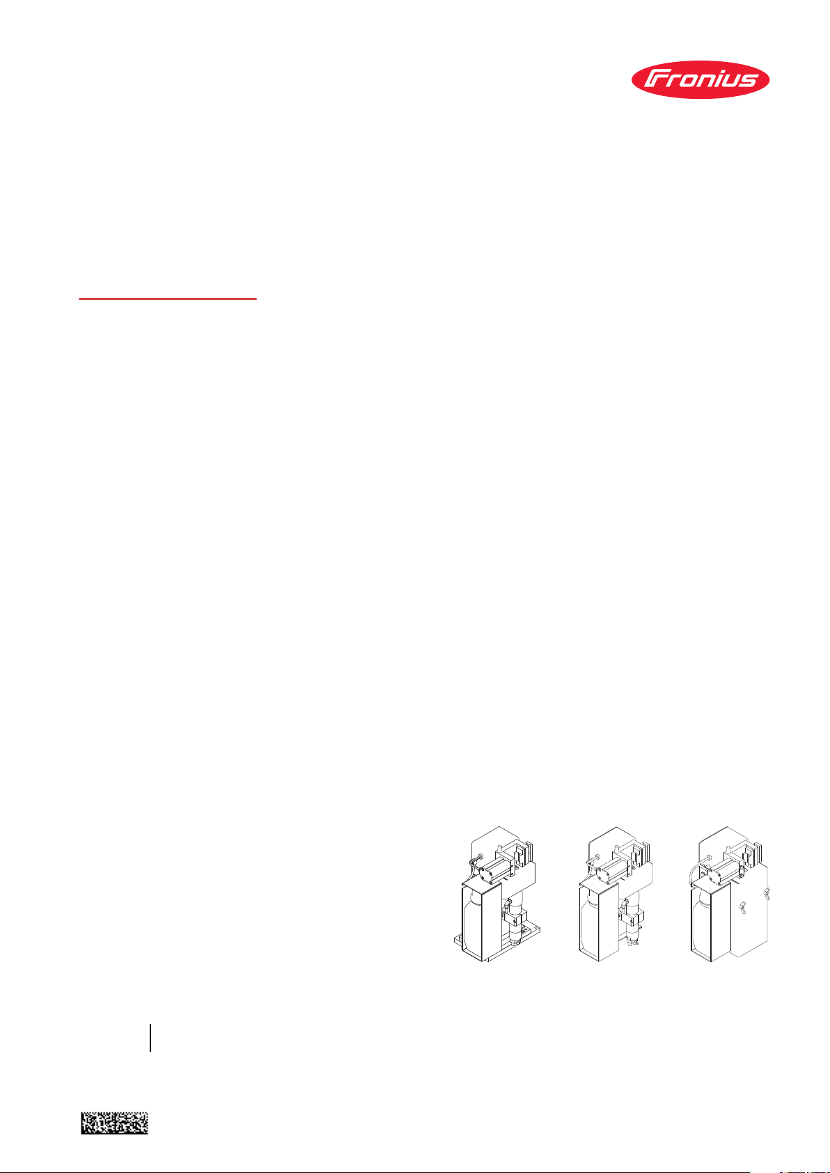
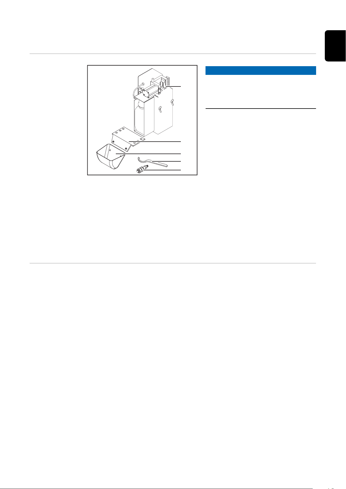
Robacta Reamer V Easy scope of supply and op-
(1)
(4)
(5)
(2)
(3)
tions
Robacta Reamer
V Easy scope of
supply
NOTE!
The "Robacta Reamer" parting agent
(item number 42,0411,8042) and the
cleaning cutter are not part of the
scope of supply.
(1) Robacta Reamer V Easy clean-
ing device
(2) Spatter tray retainer
(3) Spatter tray
(4) Tightening key for cleaning mo-
tor
(5) Compressed air relief valve
not shown:
(6) Harting Han6P connecting plug (X1) without cable
(7) Operating instructions
(8) Fixings for assembling the cleaning device:
4 screws
-
4 washers
-
4 lock washers
-
4 nuts
-
Robacta Reamer
V Easy options
The following options are available for the cleaning device:
Installation stand
-
Wire cutter
-
Suction line for canister (10 litres)
-
20
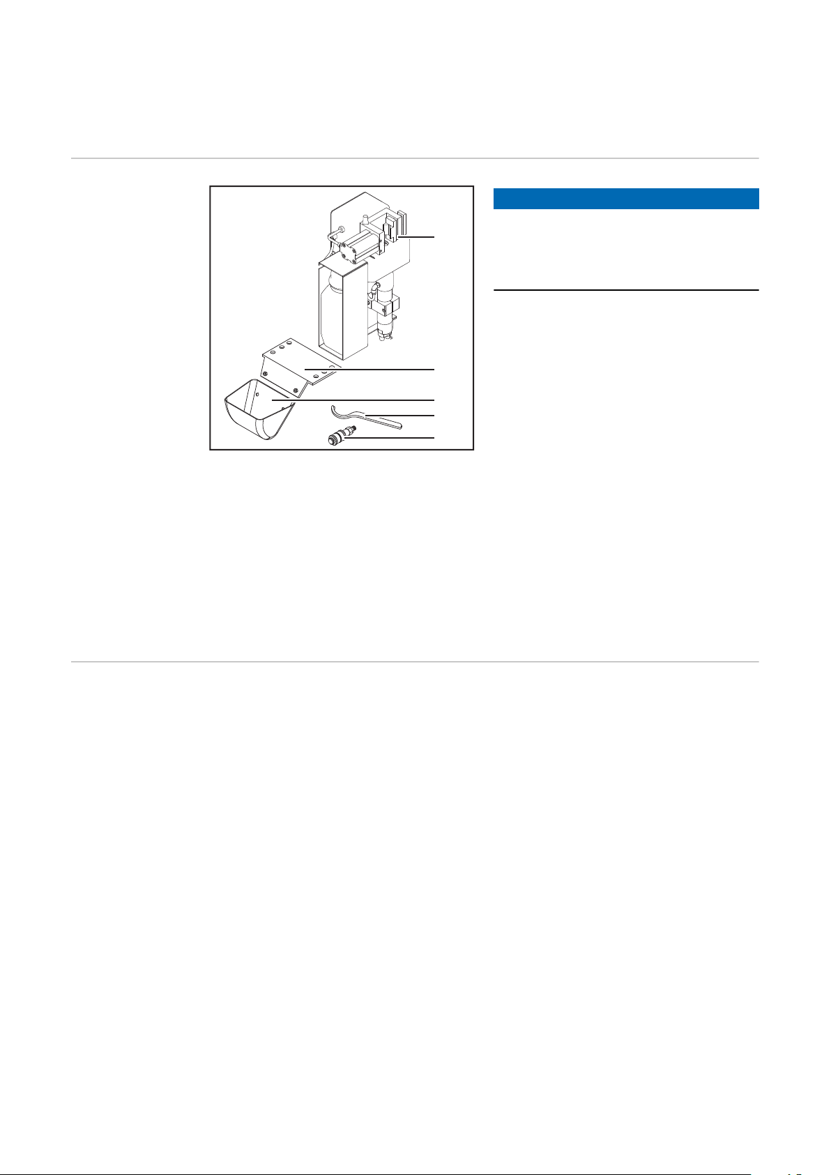
Robacta Reamer V Easy Han6P J scope of supply,
(1)
(2)
(3)
(4)
(5)
options and required components
Robacta Reamer
V Easy Han6P J
scope of supply
not shown:
(6) Harting Han6P connecting plug (X1) without cable
(7) Operating instructions
(8) Fixings for assembling the cleaning device:
4 screws
-
NOTE!
The "Robacta Reamer" parting agent
(item number 42,0411,8042) and the
cleaning cutter are not part of the
scope of supply.
(1) Robacta Reamer V Easy Han6P
(2) Spatter tray retainer
(3) Spatter tray
(4) Tightening key for cleaning mo-
(5) Compressed air relief valve
EN
J cleaning device
tor
Robacta Reamer
V Easy Han6P J
required components
Robacta Reamer
V Easy Han6P J
options
NOTE!
The mounting plate and fixings are not
part of the scope of supply for the
cleaning device, but are needed to ensure that the cleaning device is adjusted when it is installed.
The following options are available for the cleaning device:
Installation stand
-
Suction line for canister (10 litres)
-
Adjusted wire cutter
-
Mounting plates for the wire cutter including fixings
-
21
Mounting plates for the wire cutter including fixings
22
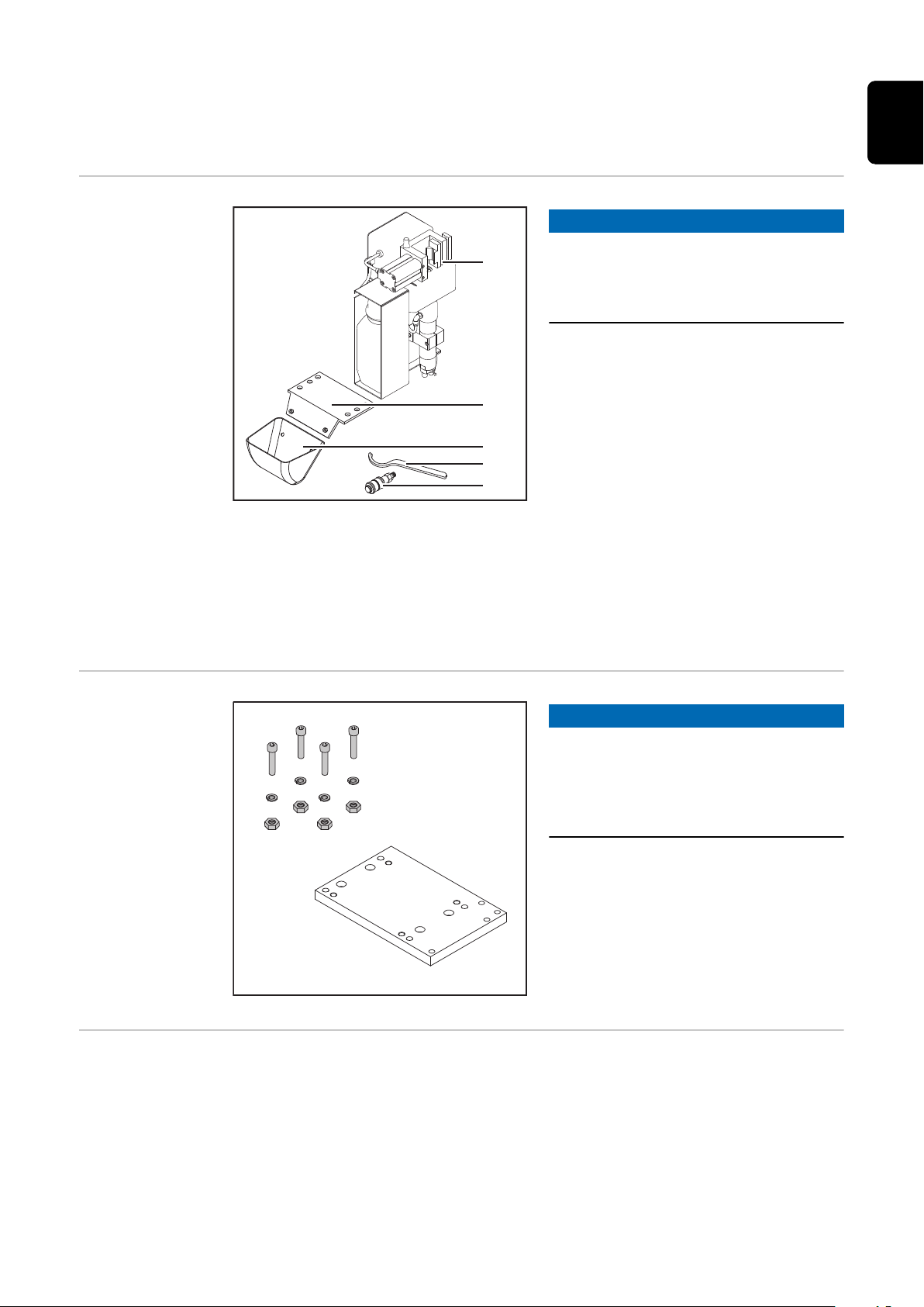
Robacta Reamer V scope of supply and options
(1)
(2)
(3)
(4)
(5)
EN
Robacta Reamer
V scope of supply
NOTE!
The "Robacta Reamer" parting agent
(item number 42,0411,8042) and the
cleaning cutter are not part of the
scope of supply.
(1) Robacta Reamer V cleaning
device
(2) Spatter tray retainer
(3) Spatter tray
(4) Tightening key for cleaning mo-
tor
(5) Compressed air relief valve
not shown:
(6) Standard I/O connecting plug (X1) without cable
(7) Operating instructions
(8) Fixings for assembling the cleaning device:
4 screws
-
4 washers
-
4 lock washers
-
4 nuts
-
Robacta Reamer
V options
The following options are available for the cleaning device:
Installation stand
-
Wire cutter
-
Suction line for canister (10 litres)
-
23

24

Controls, connections and mechan-
ical components
25

26

Safety
Safety Observe the following safety rules for all work described in the "Control ele-
ments, connections and mechanical components" section.
WARNING!
Danger due to incorrect operation and incorrectly performed work.
This can result in serious injury and damage to property.
All the work and functions described in this document must only be carried
▶
out by trained and qualified personnel.
Read and understand this document.
▶
Read and understand all the Operating Instructions for the system compon-
▶
ents, especially the safety rules.
EN
27

Robacta Reamer V Easy, Robacta Reamer V Easy
(1)
(2)
(3)
(4)
(5)
(6)
(11)
(12)
(13)
(7)
(9)
(10)
(8)
(14)
Han6P J control elements, connections and
mechanical components
Robacta Reamer
V Easy, Robacta
Reamer V Easy
Han6P J control
elements, connections and
mechanical components
NOTE!
The control elements, connections and mechanical components are shown on
the Robacta Reamer V Easy.
The control elements, connections and mechanical components are the same for
the Robacta Reamer V Easy Han6P J.
28
Side view
(1) Harting Han6P connection socket (X1)
for a + 24 V DC supply
CAUTION!
Danger from overcurrent.
Damage to the Harting Han6P (X1) connection power supply may result.
Fuse the power supply of the cleaning device with 500 mA slow-blow fuse
▶
against overcurrent.
(2) Compressed air connection
for a dry compressed air supply at 6 bar (86.99 psi)
Thread identification compressed air connection: G ¼“
(3) Parting agent container
(4) "Cleaning" screw
for manually testing all cleaning device functions:
Cleaning motor on/off
-
Lifting device up/down
-
Gas nozzle clamping device extending/retracting
-
Compressed air and parting agent supply to parting-agent injection
-
nozzle (compressed air/parting agent mixture is sprayed out of the
parting-agent injection nozzle)
Front view

(5) Parting agent adjuster
for adjusting the amount of parting agent sprayed inside the gas nozzle
(6) Lifting device
lifts the cleaning motor and the cleaning cutter when cleaning the inside
of the gas nozzle
(7) Cleaning motor with parting-agent injection nozzle
drives the cleaning cutter
(8) Compressed air connection for the wire cutter option
(9) Parting-agent injection nozzle
applies the parting agent to the inside and front of the gas nozzle
(10) Cleaning cutter
with internal through hole for the parting-agent injection nozzle
(11) "Spray parting agent" button
for manually testing the spray device - when the button is pressed, only
the spray device is activated (compressed air or a mixture of compressed
air/parting agent is sprayed from the parting-agent injection nozzle). The
other functions of the cleaning device remain inactive.
(12) Gas nozzle clamping device
holds the gas nozzle in place during cleaning
EN
(13) Protective covering
(14) TCP (ToolCenterPoint) with protective covering
Absolute zero position for setting and checking the position of the welding torch (for cleaning purposes)
CAUTION!
Danger from exposed tip of TCP.
This can result in severe injuries.
The protective covering may only be removed when setting and checking the
▶
position of the welding torch.
Before and after adjusting or checking, the protective covering must remain
▶
on the TCP.
29

Robacta Reamer V control elements, connections
(7)
(6)
(9)
(10)
(11)
(12)
(8)
and mechanical components
Robacta Reamer
V control elements, connections and mechanical components
Side view
(1) Standard I/O connection socket (X1)
for a + 24 V DC supply
CAUTION!
Danger from overcurrent.
Damage to standard I/O connection (X1) supply may result.
Fuse the power supply of the cleaning device with 500 mA slow-blow fuse
▶
against overcurrent.
(2) Compressed air connection
for a dry compressed air supply at 6 bar (86.99 psi)
Thread identification compressed air connection: G ¼“
(3) Fill-level control sensor
emits a signal once the fill level in the parting agent container falls below
a specified level
(4) Parting agent container
(5) Parting agent adjuster
for adjusting the amount of parting agent sprayed inside the gas nozzle
Front view
30
(6) Protective covering
(7) Lifting device
lifts the cleaning motor and the cleaning cutter when cleaning the inside
of the gas nozzle
(8) Cleaning motor with parting-agent injection nozzle
drives the cleaning cutter
(9) Compressed air and electrical connections for wire cutter option
(10) Cleaning cutter
with internal through hole for the parting-agent injection nozzle
 Loading...