


Operating
Instructions
Robacta Reamer V Twin
Operating Instructions
EN
42,0426,0142,EN 025-30012023


Contents
Safety rules 6
Explanation of safety notices 6
General 6
Proper use 7
Environmental conditions 7
Obligations of the operator 7
Obligations of personnel 7
Specific hazards 7
Protecting yourself and others 8
EMC Device Classifications 8
EMC measures 9
EMF measures 9
Safety measures at the installation location and during transport 9
Safety measures in normal operation 10
Commissioning, maintenance and repair 10
Safety inspection 10
Disposal 11
Safety symbols 11
Copyright 11
General 13
General 15
Principle 15
Device concept 15
Application areas 15
Scope of supply 16
Available options 16
How the wire cutter works/Maximum wire diameter 16
Warning notices on the device 17
Transport 19
Transport devices 19
Transport notices on the packaging 19
EN
Controls, connections and mechanical components 21
Safety 23
Safety 23
Robacta Reamer V Twin control elements, connections and mechanical components 24
Control elements, connections and mechanical components 24
Standard I/O connecting plug (X1) pin assignment for robot control 26
General 26
Standard I/O (X1) connecting plug pin assignment 26
Installation and commissioning 27
Safety 29
Safety 29
Ensuring that the cleaning device is depressurised 30
Before commissioning 31
Proper use 31
Operators, maintenance personnel 31
Setup regulations 31
Compressed air supply specifications 31
Measures for the safe operation of the device with untrained personnel 32
Screwing the cleaning device to the underlying surface 33
Screwing the cleaning device and installation stand to the underlying surface 33
Screwing the cleaning device to the underlying surface 33
Fitting the cleaning cutter 35
Fitting the cleaning cutter 35
Torch cleaning position 36
3

Cleaning position of the welding torch with externally routed coolant lines 36
Cleaning position of the welding torch with internally routed coolant lines 36
Fitting the clamping system for welding torches with internally routed coolant lines 37
Tools required 37
Removing the existing clamping system 37
Fitting the Twin clamping system 38
Adjusting the lifting device 41
Adjusting the lifting device 41
Installing the compressed air supply 43
Establishing the compressed air supply for the cleaning device, function of the compressed air relief valve
Starting up the parting agent nebuliser 44
Fill parting agent container (1 litre) and connect to the cleaning device 44
Connect the parting agent container (10 litres) to the cleaning device 45
Adjusting the parting agent nebuliser spray amount 46
Using the fill-level control sensor 47
Optional fill-level control sensor 47
Controls and indicators on the sensor 47
Installation adapter borehole dimensions 47
Fitting the fill-level control sensor 48
Calibrating the empty state 49
Calibrating the full state 49
Locking/unlocking the fill-level control sensor 50
Electrical connection 50
Manually checking the cleaning device functions 51
Safety 51
Checking functions manually 51
Starting up the cleaning device 53
Prerequisites for start-up 53
Start-up 53
Cleaning programme 54
Safety 54
Cleaning program sequence - overview 55
1. Wire cutter 56
2. "Parting agent level" query (option) 57
3. "Cleaning motor lowered" query 58
4. "Gas nozzle free" query 59
5. Cleaning 60
Signal waveform for cleaning 65
Signal inputs 65
Signal outputs 65
Signals not defined using time 66
Signal waveform: wire cutter (inputs and outputs) 66
43
Care, maintenance and disposal 67
Safety 69
Safety 69
Care, maintenance and disposal 71
General 71
Before each start-up 71
Daily 71
Weekly 71
Every 6 months 71
As necessary 71
Disposal 72
Adjust the swivel mechanism stop angle 73
General 73
Preparatory work 73
Adjust the swivel mechanism stop angle 74
And finally... 75
4

Troubleshooting 77
Safety 79
Safety 79
Troubleshooting 81
Errors in program sequence 81
Technical data 83
Technical data 85
Robacta Reamer V Twin 85
Appendix 87
Circuit diagram Robacta Reamer V Twin 89
Robacta Reamer V Twin pneumatic diagram 90
Declaration of conformity 91
EN
5

Safety rules
Explanation of
safety notices
DANGER!
Indicates immediate danger.
If not avoided, death or serious injury will result.
▶
WARNING!
Indicates a potentially hazardous situation.
If not avoided, death or serious injury may result.
▶
CAUTION!
Indicates a situation where damage or injury could occur.
If not avoided, minor injury and/or damage to property may result.
▶
NOTE!
Indicates a risk of flawed results and possible damage to the equipment.
General The device is manufactured using state-of-the-art technology and according to
recognised safety standards. If used incorrectly or misused, however, it can
cause:
injury or death to the operator or a third party,
-
damage to the device and other material assets belonging to the operating
-
company,
inefficient operation of the device.
-
All persons involved in commissioning, operating, maintaining and servicing the
device must:
be suitably qualified,
-
have sufficient knowledge of automated welding, and
-
read and carefully follow these operating instructions as well as the operat-
-
ing instructions for all system components.
The operating instructions must always be at hand wherever the device is being
used. In addition to the operating instructions, attention must also be paid to any
generally applicable and local regulations regarding accident prevention and environmental protection.
All safety and danger notices on the device
must be in a legible state,
-
must not be damaged,
-
must not be removed,
-
must not be covered, pasted or painted over.
-
For the location of the safety and danger notices on the device, refer to the section headed "General" in the operating instructions for the device.
Before commissioning the device, rectify any faults that could compromise
safety.
This is for your personal safety!
6

Proper use The device is to be used exclusively for its intended purpose.
The device is intended solely for the mechanical cleaning of Fronius robot welding torches in automatic mode.
Any use above and beyond this purpose is deemed improper. The manufacturer
shall not be held liable for any damage arising from such usage.
Proper use includes:
carefully reading these operating instructions
-
following all the instructions and safety rules in these operating instructions
-
performing all stipulated inspection and maintenance work
-
The device is designed for use in industry and the workshop. The manufacturer
accepts no responsibility for any damage caused through use in a domestic setting.
The manufacturer likewise accepts no liability for inadequate or incorrect results.
EN
Environmental
conditions
Obligations of
the operator
Operation or storage of the device outside the stipulated area will be deemed as
not in accordance with the intended purpose. The manufacturer shall not be held
liable for any damage arising from such usage.
Ambient temperature range:
during operation: 0 °C to + 40 °C (32 °F to 104 °F)
-
during transport and storage: -25 °C to +55 °C (-13 °F to 131 °F)
-
Relative humidity:
up to 50 % at 40 °C (104 °F)
-
up to 90 % at 20 °C (68 °F)
-
Keep ambient air free from dust, acids, corrosive gases and substances, etc.
Can be used at altitudes of up to 2000 m (6500 ft)
The operator must only allow persons to work with the device who:
are familiar with the fundamental instructions regarding safety at work and
-
accident prevention and have been instructed in how to use the device
have read and understood these operating instructions, especially the sec-
-
tion "safety rules", and have confirmed as much with their signatures
are trained to produce the required results.
-
Checks must be carried out at regular intervals to ensure that operators are
working in a safety-conscious manner.
Obligations of
personnel
Specific hazards Stay out of the working area of the robot.
Before using the device, all persons instructed to do so undertake:
to observe the basic instructions regarding safety at work and accident pre-
-
vention
to read these operating instructions, especially the "Safety rules" section and
-
sign to confirm that they have understood them and will follow them.
Before leaving the workplace, ensure that people or property cannot come to any
harm in your absence.
7

The device must be incorporated into a higher-level safety system within a secured area.
If this area has to be accessed when setup and maintenance work is carried out,
make sure that
the entire system is switched off for the duration of the work in this area
-
and that it is prevented from starting up accidentally, e.g. as the result of a
-
control fault.
If untrained operators have access to the device, its compressed air supply must
be disconnected for the duration of work in accordance with "Performance Level
d" of the ISO 13849-1 standard.
In addition to these Operating Instructions, the safety rules issued by the robot
manufacturer must also be observed.
Keep your body, especially your hands, face, hair, clothing and all tools away from
moving parts, such as:
rotating cleaning cutter
-
upwards/downwards travelling cleaning motor
-
extending/retracting gas nozzle clamping device
-
wire cutter
-
Do not touch cleaning cutters immediately after use - risk of burns. Observe the
special safety rules in the Operating Instructions for handling cleaning cutters.
Protecting yourself and others
Protect hands, face and eyes against flying parts (shavings, etc.) and compressed
air/parting agent mixture escaping from the parting-agent injection nozzle.
Covers may only be opened/removed for the duration of any maintenance, installation or repair work.
During operation
Ensure that all covers are closed and fitted properly
-
Keep all covers closed
-
Anyone working with the device exposes themselves to numerous risks. In addition to these Operating Instructions, the safety rules of the manufacturer of the
entire welding system must also be observed.
Keep all persons, especially children, out of the working area while any devices
are in operation or welding is in progress. If, however, there are people in the vicinity:
Make them aware of all the dangers and health risks (crushing from mechan-
-
ically-powered parts, injury from cleaning cutter, flying shavings and similar
matter, escaping compressed air/parting agent mixture, flying sparks,
dazzling by arc, inhaling of harmful welding fumes, noise, possible danger
from mains or welding current, etc.)
Provide suitable protective equipment
-
Alternatively, erect suitable safety screens/curtains
-
EMC Device
Classifications
8
Devices in emission class A:
Are only designed for use in industrial settings
-
Can cause line-bound and radiated interference in other areas
-
Devices in emission class B:
Satisfy the emissions criteria for residential and industrial areas. This is also
-
true for residential areas in which the energy is supplied from the public lowvoltage mains.

EMC device classification as per the rating plate or technical data.
EMC measures In certain cases, even though a device complies with the standard limit values for
emissions, it may affect the application area for which it was designed (e.g. when
there is sensitive equipment at the same location, or if the site where the device
is installed is close to either radio or television receivers).
If this is the case, then the operator is obliged to take appropriate action to rectify the situation.
Check for possible problems, and check and evaluate neighbouring devices' resistance to interference according to national and international requirements:
Safety devices
-
Power, signal and data transfer lines
-
IT and telecommunications devices
-
Measuring and calibrating devices
-
Supporting measures for avoidance of EMC problems:
Mains supply
1.
If electromagnetic interference arises despite correct mains connection,
-
additional measures are necessary (e.g. use a suitable line filter).
Control lines
2.
must be kept as short as possible
-
must run close together (to avoid EMF problems)
-
must be kept well apart from other leads
-
Equipotential bonding
3.
Shield, if necessary
4.
Shield off other nearby devices
-
Shield off entire welding installation
-
EN
EMF measures Electromagnetic fields may pose as yet unknown risks to health:
Effects on the health of persons in the vicinity, e.g. those with pacemakers
-
and hearing aids
Individuals with pacemakers must seek advice from their doctor before ap-
-
proaching the device or any welding that is in progress
For safety reasons, maintain as large a distance as possible between the
-
welding power-leads and the head/torso of the welder
Do not carry welding power-leads and hosepacks over the shoulders or wind
-
them around any part of the body
Safety measures
at the installation location and
during transport
A device toppling over could easily kill someone. Place the device horizontally on
a level, firm and solid surface and anchor it securely to prevent it toppling over.
Special regulations apply in rooms at risk of fire or explosion
Observe relevant national and international regulations.
-
Use internal directives and checks to ensure that the workplace environment is
always clean and clearly laid out.
When transporting the device, observe the relevant national and local guidelines
and accident prevention regulations. This applies especially to guidelines regarding the risks arising during transport.
After transporting the device, it must be visually inspected for damage before
commissioning. Any damage must be repaired by trained service technicians before commissioning the device.
9

Safety measures
in normal operation
Only operate the device if all safety devices are fully functional. If the safety
devices are not fully functional, there is a risk of
injury or death to the operator or a third party,
-
damage to the device and other material assets belonging to the operator,
-
inefficient operation of the device.
-
Any safety devices that are not functioning properly must be repaired before
switching on the device.
Never bypass or disable safety devices.
Before switching on the device, ensure that no one is likely to be endangered.
Check the device at least once a week for obvious damage and proper functioning of safety devices.
Only use suitable original parting agent from the manufacturer.
-
Observe the information on the parting agent safety data sheet when hand-
-
ling parting agent. The parting agent safety data sheet may be obtained from
your service centre or downloaded from the manufacturer's website.
Do not mix the manufacturer's parting agent with other parting agents.
-
If damage results from using a different parting agent, the manufacturer ac-
-
cepts no liability. In addition, no warranty claims will be entertained.
Used parting agent must be disposed of properly in accordance with the rel-
-
evant national and international regulations.
Commissioning,
maintenance and
repair
Safety inspection
It is impossible to guarantee that bought-in parts are designed and manufactured to meet the demands made of them, or that they satisfy safety requirements.
Use only original spare and wearing parts (also applies to standard parts).
-
Do not carry out any modifications, alterations, etc. to the device without the
-
manufacturer's consent.
Components that are not in perfect condition must be replaced immediately.
-
When ordering, please give the exact designation and part number as shown
-
in the spare parts list, as well as the serial number of your device.
The housing screws provide the ground conductor connection for earthing the
housing parts.
Only use original housing screws in the correct number and tightened to the specified torque.
The manufacturer recommends that a safety inspection of the device is performed at least once every 12 months.
A safety inspection should be carried out by a qualified electrician
after any changes are made
-
after any additional parts are installed, or after any conversions
-
after repair, care and maintenance has been carried out
-
at least every twelve months.
-
10
For safety inspections, follow the appropriate national and international standards and directives.
Further details on safety inspection and calibration can be obtained from your
service centre. They will provide you on request with any documents you may require.

Disposal Waste electrical and electronic equipment must be collected separately and re-
cycled in an environmentally responsible manner in accordance with the EU Directive and national law. Used equipment must be returned to the distributor or
through a local, authorised collection and disposal system. Proper disposal of the
old device promotes sustainable recycling of material resources. Ignoring this
may lead to potential health/environmental impacts.
Packaging materials
Collected separately. Check your municipality’s regulations. Reduce the volume
of the box.
Safety symbols Devices with the CE mark satisfy the essential requirements of the applicable
directives (e.g. low-voltage and electromagnetic compatibility directives, machinery directive).
Devices with the CSA test mark satisfy the requirements of the relevant standards in Canada and the USA.
Copyright Copyright of these operating instructions remains with the manufacturer.
The text and illustrations are all technically correct at the time of printing. We
reserve the right to make changes. The contents of the operating instructions
shall not provide the basis for any claims whatsoever on the part of the purchaser. If you have any suggestions for improvement, or can point out any mistakes that you have found in the instructions, we will be most grateful for your
comments.
EN
11

12

General
13

14

General
Principle The Robacta Reamer V Twin is used for
the automatic cleaning of MIG/MAG
welding torches. The Robacta Reamer
V Twin allows you to clean the inside
and front of the gas nozzle on a wide
range of welding torch shapes. The result is a significant increase in the service life of wearing parts. At the same
time, evenly applying parting agent
prevents the build-up of dirt.
Device concept The clamping device on the front of the Robacta Reamer V Twin holds the gas
nozzle in place during cleaning. A cleaning cutter is used to clean the nozzle.
After the cleaning process, a parting agent is applied to the inside and front of
the gas nozzle through the spray nozzle that is fixed in the middle of the cleaning
motor.
EN
Application
areas
The Robacta Reamer V Twin is fitted with a wire cutter as standard. During the
cleaning process, the Robacta Reamer V Twin shortens both wire electrodes to a
defined length ready for the next welding process.
A robust fitting base is available for the installation of the Robacta Reamer V
Twin.
The cleaning device is exclusively intended for use in robot and other automated
applications, and can be used for a wide range of materials.
The main application areas are:
Automotive and component supply industry
-
Equipment construction
-
Chemical plant construction
-
Machine and tracked vehicle manufacturing
-
Construction machinery and special vehicles
-
NOTE!
TWIN welding torches with a contact tip tilt angle of 4° cannot be cleaned with
the Robacta Reamer V Twin!
Alternatives:
Robacta Reamer Single/Twin
▶
or
Robacta TC 2000 Twin
▶
15

Scope of supply
(1)
(2)
(3)
(4)
NOTE!
The "Robacta Reamer" parting agent
(item number 42,0411,8042) and the
cleaning cutter are not part of the
scope of supply.
(1) Robacta Reamer V Twin clean-
ing device with wire cutter
(2) Spatter tray
(3) Tightening key for cleaning mo-
tor
(4) Compressed air relief valve
not shown:
(5) Standard I/O connecting plug (X1) without cable
(6) Operating instructions
(7) Fixings for assembling the cleaning device:
4 screws
-
4 washers
-
4 lock washers
-
4 nuts
-
Available options
How the wire
cutter works/
Maximum wire
diameter
The following options are available for the cleaning device:
Installation stand
-
Cleaning cutter adjustment aid
-
Level sensor
-
The wire cutter opens and closes when there is an active signal from the robot
control.
Two wire electrodes with a diameter of up to 1.6 mm (0.063 in.) can be cut at the
same time by the cleaning device wire cutter.
NOTE!
If you change over to a new welding torch, the wire cutter must be reset!
16

Warning notices
Type
Art.No.
Chargen No.
U1
I1
Wels - Austria
p
max
24 V
6 bar (87psi.)
on the device
The Robacta Reamer V Twin is fitted with warning notices and a rating plate. The
warning notices and rating plate must not be removed or painted over.
EN
Warning notices affixed to the Robacta Reamer V Twin
WARNING! Risk of serious injury from:
mechanically powered parts
-
compressed air/parting agent mixture escaping from the part-
-
ing-agent injection nozzle
flying parts (shavings, etc.)
-
Keep device free from current and pressure during maintenance
and servicing.
Do not use the functions described here until you have thoroughly
read and understood the following documents:
these operating instructions
-
all the operating instructions for the system components, es-
-
pecially the safety rules
For indoor use only
17

Wear eye protection
Notice warning of automatic start-up of the device
18

Transport
EN
Transport
devices
Transport notices on the
packaging
The device is to be transported by the following devices:
On pallets using a forklift truck
-
On pallets using a lift truck
-
Manual
-
WARNING!
Danger from machines and objects falling.
This can result in serious injury and damage to property.
Secure the device to prevent it from falling over when transporting on a fork-
▶
lift truck or lift truck.
Avoid sudden changes in direction, braking or acceleration.
▶
CAUTION!
Danger due to improper transport.
This can result in damage to property.
Observe the transport notices on the device packaging.
▶
19

20

Controls, connections and mechan-
ical components
21

22

Safety
Safety Observe the following safety rules when using all functions described in the
"Controls, connections and mechanical components" section.
WARNING!
Danger from incorrect operation!
This can result in serious injury and damage to property.
The functions described must only be used by trained and qualified person-
▶
nel.
Do not use the functions described here until you have fully read and under-
▶
stood the following documents:
these Operating Instructions,
all the Operating Instructions for the system components, especially the
safety rules
EN
23

Robacta Reamer V Twin control elements, con-
(7)
(6)
(1)
(2)
(3)
(4)
(5)
(8)
(13)
(9)
(12)
(10)
(11)
nections and mechanical components
Control elements, connections and mechanical components
Side view
(1) Standard I/O connection socket (X1)
For a + 24 V DC supply
CAUTION!
Danger from overcurrent.
Damage to the standard I/O (X1) connection supply may result.
Secure supply against overcurrent with a 500 mA slow-blow fuse.
▶
(2) Compressed air connection
For a compressed air supply at 6 bar (86.99 psi)
Compressed air connection thread identification: G ¼"
(3) "Clamp gas nozzle/Cleaning motor on" screw
For manually checking the gas nozzle clamping device and the cleaning
motor (gas nozzle clamping device extends/retracts, cleaning motor
off/on)
(4) "Lifting device up/down" screw
For manually checking the lifting device (lifting device moves up/down)
(5) "Spray parting agent" screw
For manually checking the spray device (compressed air or compressed
air/parting agent mixture is sprayed out of the parting-agent injection
nozzle)
Front view
24
(6) Parting agent adjuster
For setting the amount of parting agent applied
(7) Parting agent container
(8) Lifting device
Lifts the cleaning motor and the cleaning cutter when cleaning the inside
of the gas nozzle

(9) Cleaning motor with parting-agent injection nozzle
(14)
(15)
The cleaning motor drives the cleaning cutter
(10) Protective cover
(11) Cleaning cutter
With internal through hole for the parting-agent injection nozzle
(12) Gas nozzle clamping device
Holds the gas nozzle in place during cleaning
(13) Wire cutter
EN
Side view
(14) Compressed air and electrical connection for the wire cutter
(15) Parting-agent injection nozzle
Applies the parting agent to the inside and front of the gas nozzle
25

Standard I/O connecting plug (X1) pin assign-
1
2
11
10
9
8
7
6
5
4
3
12
13
14
15
16
17
ment for robot control
General
Standard I/O
(X1) connecting
plug pin assignment
CAUTION!
Danger from overcurrent.
Damage to the standard I/O (X1) connection supply may result.
Secure the power supply of the cleaning device against overcurrent with a
▶
500 mA slow-blow fuse.
NOTE!
To avoid malfunction, keep the cable length between the cleaning device and robot control as short as possible.
The standard I/O (X1) connecting plug for connecting the cleaning device to the
robot control is part of the scope of supply. The cable harness must be adapted
to the connection technology on the robot control.
Input and output signals on the
Robacta Reamer V Twin:
Clamp gas nozzle/Cleaning motor
1.
ON (cleaning cutter turning) input
signal + 24 V DC
GND general
2.
Cleaning motor UP input signal
3.
(cleaning cutter moves to cleaning
position) + 24 V DC
Spray parting agent input signal +
4.
24 V DC
+ 24 V DC (supply)
5.
Gas nozzle free output signal
6.
26
Standard I/O (X1) connecting plug pin assignment - cable-end view
Gas nozzle clamped output signal
7.
Not assigned
8.
Parting agent level OK output signal
9.
Cleaning motor lowered output signal (cleaning cutter in start position)
10.
Cleaning motor raised output signal (cleaning cutter in cleaning position)
11.
Cut wire electrode input signal + 24 V DC
12.
Swivel mechanism left output signal
13.
Swivel mechanism right output signal
14.
Move swivel mechanism to the left input signal
15.
Move swivel mechanism to the right input signal
16.
Not assigned
17.

Installation and commissioning
27

28

Safety
Safety Observe the following safety rules for all work described in the "Installation and
commissioning" section.
WARNING!
Danger due to incorrect operation and incorrectly performed work.
This can result in serious injury and damage to property.
All activities described in these Operating Instructions may only be carried
▶
out by trained and qualified personnel.
All functions described in these Operating Instructions may only be used by
▶
trained and qualified personnel.
Do not carry out any of the work or use any of the functions described until
▶
you have fully read and understood the following documents:
these Operating Instructions,
all the Operating Instructions for the system components, especially the
safety rules.
WARNING!
EN
Risk of machines starting automatically!
This can result in serious injury and damage to property.
In addition to these Operating Instructions, also observe the safety rules is-
▶
sued by the manufacturer of the robot and welding system.
Ensure that all protective measures have been taken and will remain in place
▶
while you are in the working area of the robot.
WARNING!
Danger from mechanically powered parts, flying parts (shavings, etc.) and compressed air/parting agent mixture escaping from the parting-agent injection
nozzle.
This can result in severe injuries.
Before carrying out any work on the cleaning device or the connected system
▶
components, disconnect the customer's compressed air and power supplies
from the cleaning device and the connected system components, and ensure
that they remain disconnected until all work is complete.
IMPORTANT! Observe the following section "Ensuring that the cleaning device is
depressurised".
29

WARNING!
Danger from power supply and/or compressed air supply to the cleaning device!
The following conditions can lead to serious injuries:
rotating cleaning cutters
lifting device moving up/down
extending/retracting gas nozzle clamping device
activated wire cutter
flying parts (shavings, etc.)
compressed air/parting agent mixture escaping from the parting-agent injection
nozzle
If work has to be performed on the cleaning device while it is being supplied with
voltage and/or compressed air:
keep your body, especially your hands, face, hair, any objects and all clothing
▶
away from the cleaning cutter, lifting device, gas nozzle clamping device, wire
cutter and parting-agent injection nozzle
Wear ear protection
▶
Wear protective goggles with side protection
▶
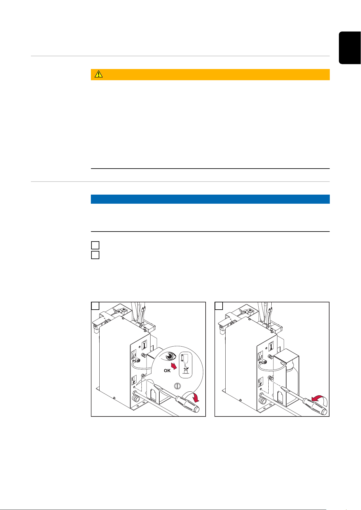
Ensuring that
the cleaning
device is depressurised
Attempt to briefly activate the cleaning device without any compressed air supply to check whether the cleaning device is depressurised. Proceed as follows:
Take protective measures:
1
The cleaning cutter, lifting device, gas nozzle clamping device, wire cutter
-
and parting-agent injection nozzle could start up. Therefore keep your
body, especially your hands, face and hair, any objects and all clothing
away from the parts referred to above
Wear ear protection
-
Wear protective goggles with side protection
-
Ensure that the cleaning device has been disconnected from the compressed
2
air supply
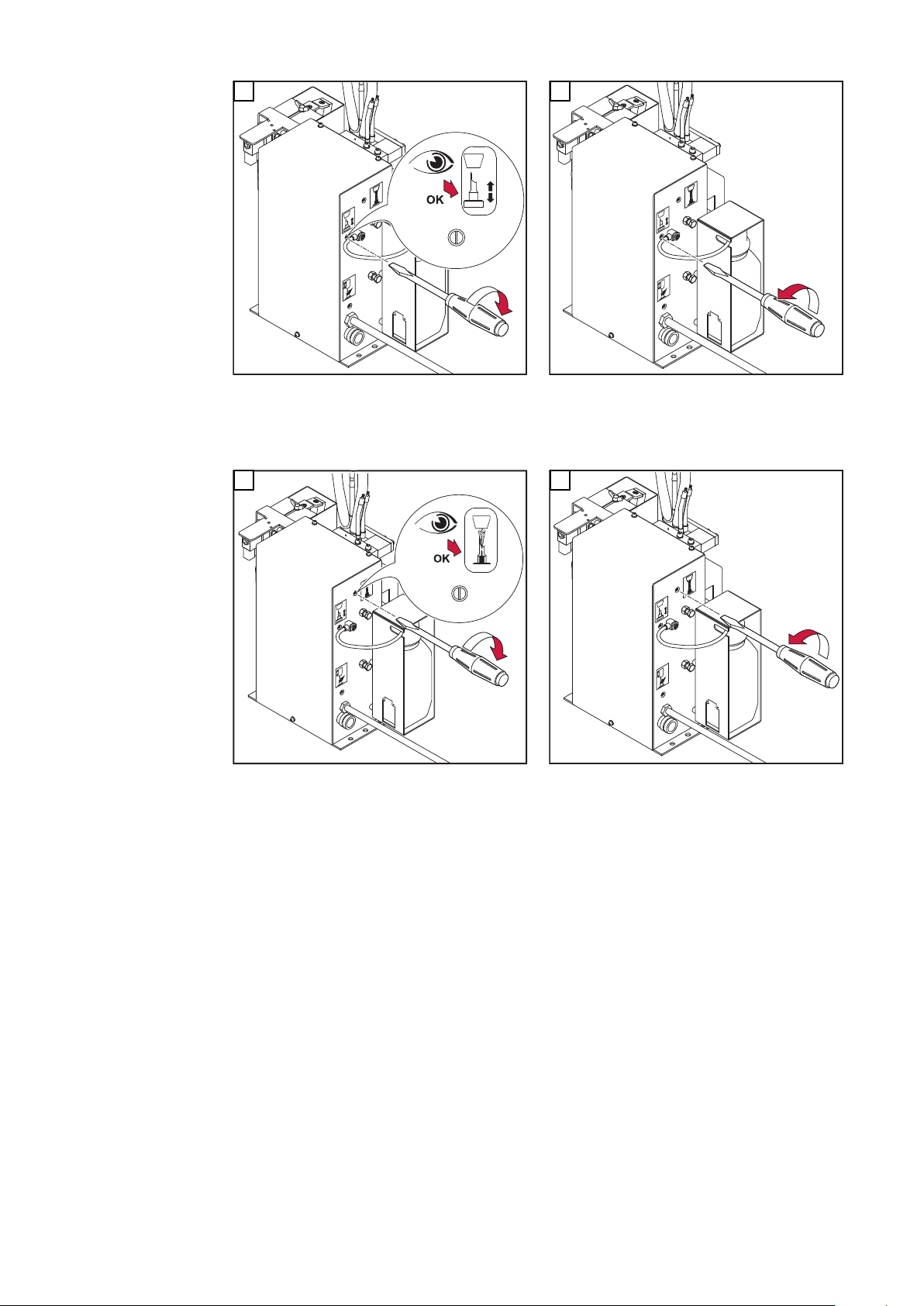
Briefly turn the "Lifting device up/down" screw on the Robacta Reamer V
3
Twin 90° to the right, then turn it straight back to its original position.
If the cleaning device does not respond to the turning of the screw, the
-
cleaning device is depressurised
If the cleaning device responds to the turning of the screw, the cleaning
-
device is still connected to a compressed air supply. If this is the case, you
must disconnect the cleaning device from the compressed air supply and
check again that the cleaning device is depressurised before starting work
30

Before commissioning
Proper use The cleaning device is to be used exclusively for cleaning Fronius robot welding
torches, especially the gas nozzle and its interior, in automatic mode and within
the scope of the technical data. Any use above and beyond this purpose is
deemed improper. The manufacturer shall not be held liable for any damage
arising from such usage.
Proper use includes:
carefully reading these operating instructions
-
following all the instructions and safety rules in these operating instructions
-
performing all stipulated inspection and maintenance work
-
EN
Operators, maintenance personnel
Setup regulations
WARNING!
Risk of machines starting automatically.
This can result in serious injury and damage to property.
The device must only be operated/serviced by 1 person at a time.
▶
Ensure that there is only 1 person within the working area of the device when
▶
the device is being worked on.
The cleaning device is tested to protection class IP 21, meaning:
Protection against penetration by solid foreign bodies with diameters > 12.5
-
mm (0.49 in.)
No protection against the ingress of water
-
The device must not be set up and operated outdoors. The built in electrical
parts must be protected from direct wetting.
WARNING!
Danger from machines falling or toppling over.
This can result in serious injury and damage to property.
Always secure the cleaning device to the underlying surface.
▶
Compressed air
supply specifications
To ensure that the cleaning device functions correctly, the following compressed
air supply specifications must be met:
Establish compressed air supply using a pressure limiter and compressed air
-
filter
Provide compressed air quality conforming to ISO 8573-1:2001, class 7 4 3,
-
instrument air
-
Solid particle concentration £ 10 mg/m
Vapour pressure dew point £ + 3 °C
-
-
Oil concentration £ 1 mg/m
3
3
31

Measures for the
safe operation of
the device with
untrained personnel
If untrained operators have access to the device, its compressed air supply must
be disconnected for the duration of work in accordance with 'Performance Level
d' of the ISO 13849-1 standard.
To ensure that the compressed air supply is interrupted as required, MS6-SV
pressure build-up and pressure relief valves from FESTO are recommended.
32
Screwing the cleaning device to the underlying
4 x
surface
Screwing the
cleaning device
and installation
stand to the underlying surface
WARNING!
Danger from machines toppling over or falling.
This can result in serious personal injury and damage to property.
Different fixings may be required to set up the installation stand depending
▶
on the type of underlying surface (foundation).
Fixings are therefore not included in the scope of supply of the installation
▶
stand. The installer is responsible for selecting the right type of fixing.
Place the optionally available installation stand on a level, firm and vibration-
1
free surface (foundation)
Position the installation stand in such a way that the distance the robot
-
has to travel to the cleaning device on the installation stand is as short as
possible
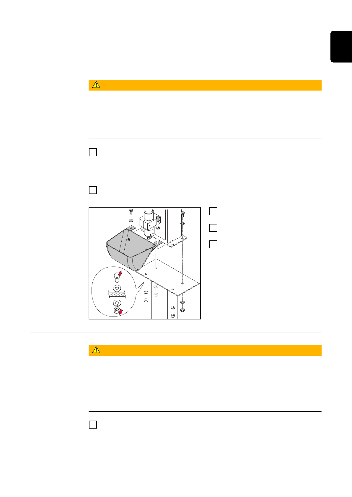
Screw the installation stand to the underlying surface (foundation) using the
2
appropriate fixings
Position the cleaning device on the
3
installation stand
Position the spatter tray on the
4
cleaning device as shown
Securely screw the cleaning device
5
and spatter tray to the installation
stand as shown. Use the fixings
supplied with the cleaning device
EN
Screwing the
cleaning device
to the underlying
surface
WARNING!
Different fixings may be required to set up the device depending on the type of
underlying surface (foundation).
The fixings supplied may only be used on an underlying surface (foundation)
thickness of 5 mm (0.197 in.) or less.
Do not use the fixings supplied to set up the device on an underlying surface
(foundation) thickness greater than 5 mm (0.197 in.). In this situation the installer is responsible for selecting the right type of fixing.
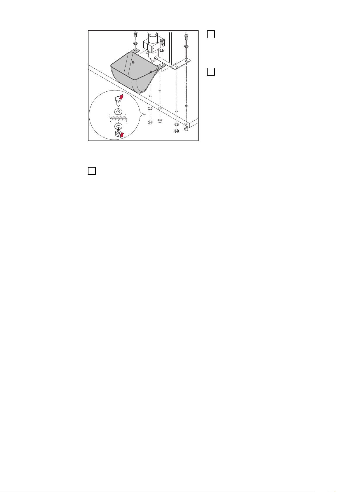
Place the cleaning device on a level, firm and vibration-free surface (founda-
1
tion)
Position the cleaning device in such a way that the distance the robot has
-
to travel to the cleaning position is as short as possible
33
4 x
Position the spatter tray on the
2
cleaning device as shown
For an underlying surface (foundation)
thickness of less than 5 mm (0.197 in.):
Securely screw the cleaning device
3
and spatter tray to the underlying
surface (foundation) as shown using the fixings supplied
For an underlying surface (foundation) thickness greater than 5 mm (0.197 in.) or
an installation different to that shown above:
Securely screw the cleaning device and spatter tray to the underlying surface
3
(foundation) using the appropriate fixings chosen
34
Fitting the cleaning cutter
EN
Fitting the
cleaning cutter
CAUTION!
Danger due to cleaning cutter that has become very hot through use.
This can result in severe burns.
Before handling cleaning cutters, allow cleaning cutter to cool to room tem-
▶
perature (+25 °C, +77 °F).
CAUTION!
Danger from incompatible wearing parts.
This can result in damage to property and malfunctions.
Only use the device manufacturer's contact tips, gas nozzles and cleaning
▶
cutters. No liability is accepted for damage caused by the use of contact tips,
gas nozzles or cleaning cutters from third-party manufacturers.
The cleaning cutter is not part of the scope of suppl.. Consult the manufacturer's
spare parts list for the appropriate cleaning cutter: https://spareparts.froni-
us.com/
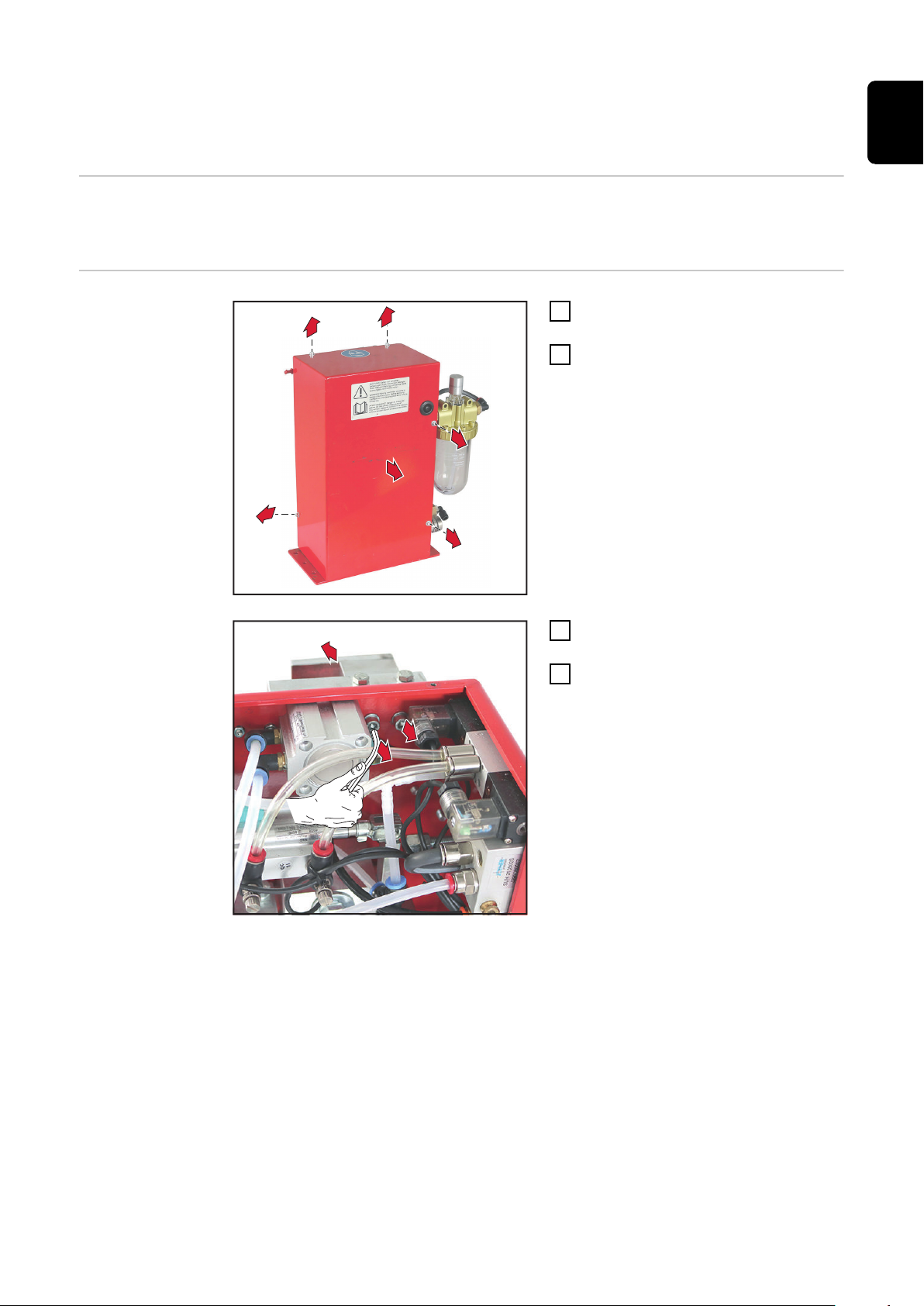
Remove the protective covering from the cleaning device
1
2
Fit the protective covering to the cleaning device in its original position
3
35
Torch cleaning position
10 mm
(0.39 in.)
(1)
(1)
Cleaning position of the welding torch with externally routed
coolant lines
Cleaning position of the welding torch with internally routed
coolant lines
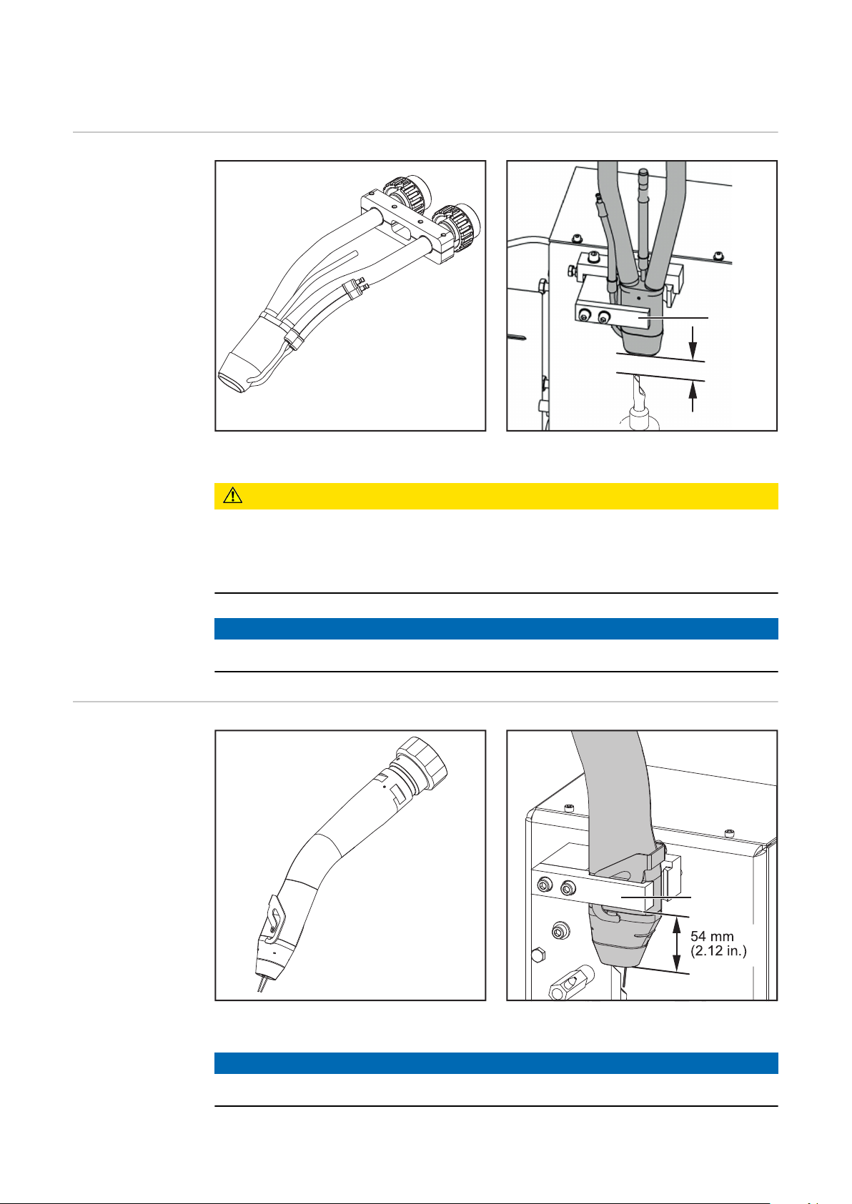
Welding torch with externally routed coolant
lines
CAUTION!
Danger due to incorrectly positioned welding torch!
This may damage the coolant lines on the welding torch.
Ensure that the coolant lines on the gas nozzle cannot be damaged when the
▶
welding torch is moved into/out of the gas nozzle clamping device.
NOTE!
The gas nozzle must sit on the inside of the holder (1).
Cleaning position
36
Welding torch with internally routed coolant
lines
NOTE!
The gas nozzle must sit on the inside of the holder (1).
Cleaning position
Fitting the clamping system for welding torches
2
1
1
1
1
1
3
3
4
with internally routed coolant lines
Tools required
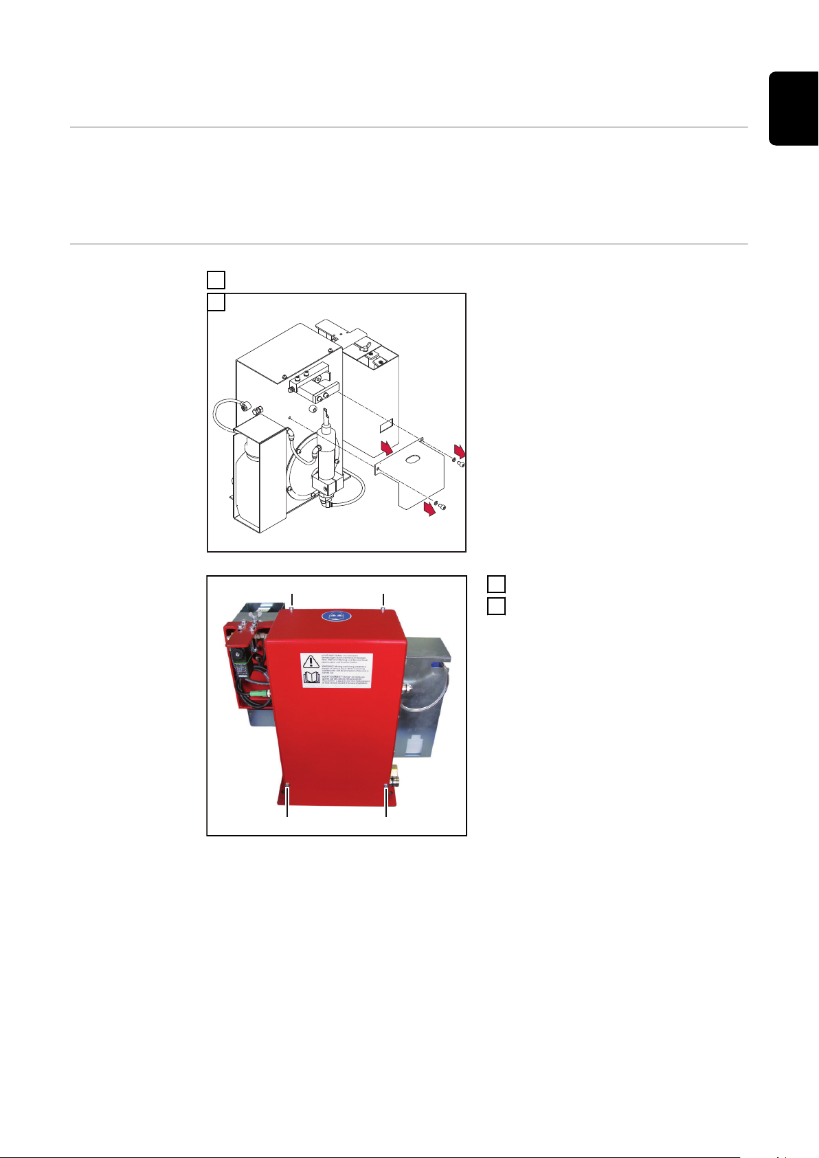
Removing the
existing clamping system
Torx® screwdriver, TX25
-
3 mm & 5 mm Allen key
-
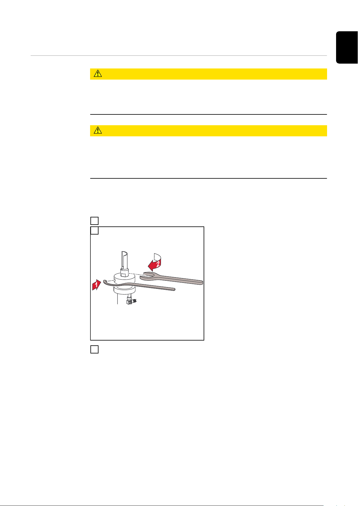
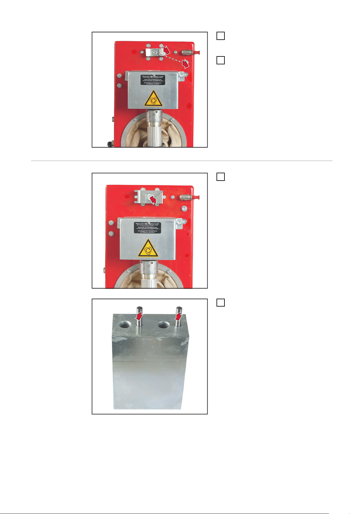
Undo the 5 Allen screws
1
size 3 mm
Remove the housing cover
2
EN
Undo the 2 Allen screws
3
size 5 mm
Remove the 3-part clamping
4
device element
37
6
5
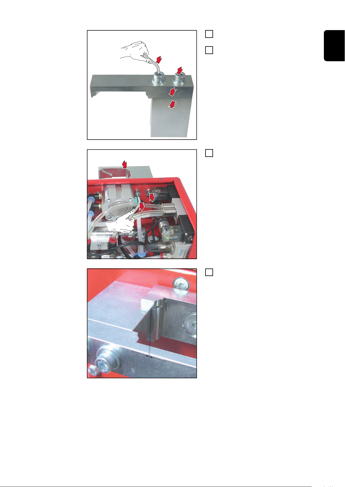
Remove the Allen countersunk
1
2
2
5
screw
size 5 mm
Remove the clamping device ele-
6
ment
Fitting the Twin
clamping system
Secure the clamping device ele-
1
ment with the M8 x 25 mm Allen
countersunk screw
size 5 mm
Insert two 3 x 12 mm pins
2
38
3
3
4
4
Assemble the clamping device ele-
5
5
5
0
,5 mm
3
ments
Screw together the clamping
4
device elements with two washers
and two M6 x 25 mm Allen screws
size 5 mm
Fit the clamping device elements
5
with two M6 x 16 mm Allen screws
size 5 mm
EN
Make sure that there is a gap of ap-
6
prox. 0.5 mm between the clamping device elements.
39
8
7
8
8
8
8
Fit the housing cover
7
Secure the housing cover with five
8
M4 x 8 mm Allen screws
size 3 mm
40

Adjusting the lifting device
1
2
1
EN
Adjusting the
lifting device
To make it easier to adjust the lifting device, it is advisable to fit one of the following adjustment aids to the torch body:
Robacta Twin 500 adjustment aid, item no. 42,0001,5559
-
Robacta Twin 900 adjustment aid, item no. 42,0001,5560
-
An adjustment aid is not necessary when the gas nozzle is open, as the welding
torch is clamped above the gas nozzle. The gas nozzle can be removed beforehand. The bracket must be back in the starting position. When the gas nozzle is
mounted, the bracket must be closed.
NOTE!
Ensure that the coolant lines on the gas nozzle cannot be damaged by the extending/retracting gas nozzle clamping device.
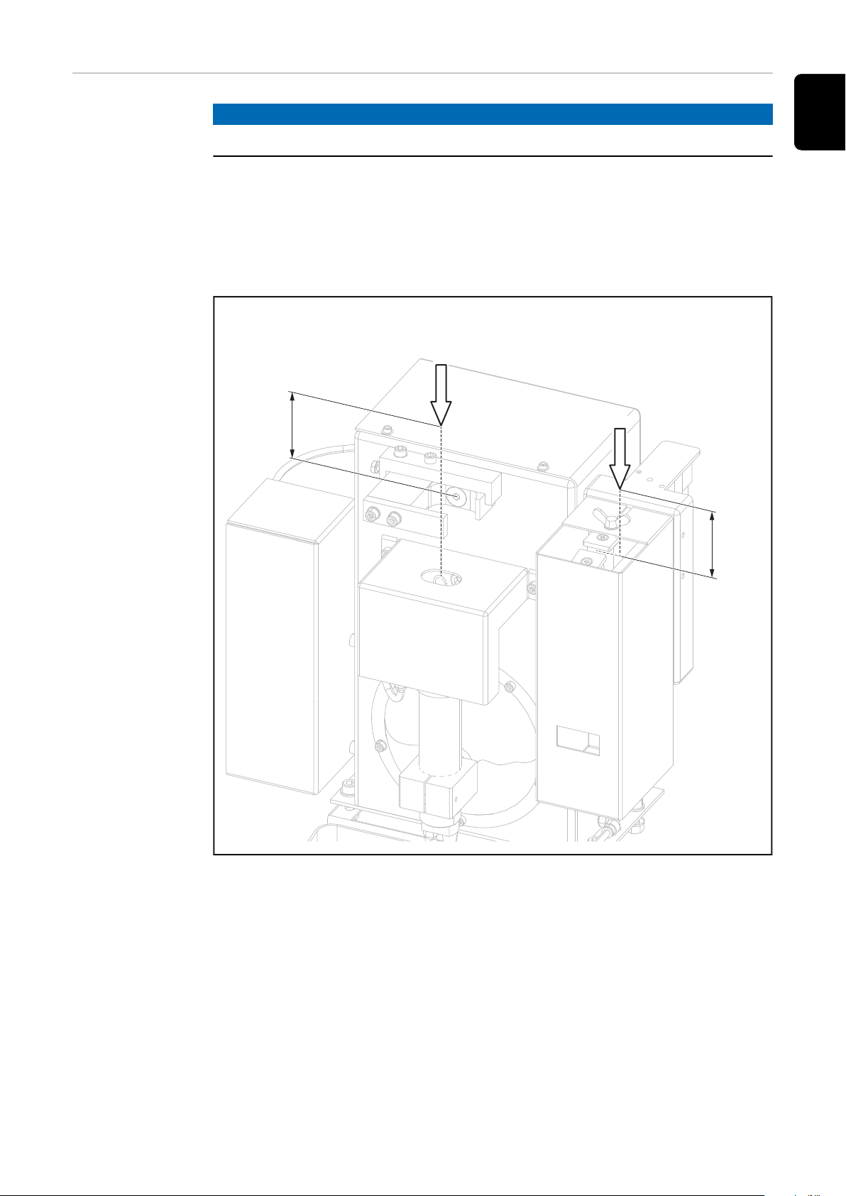
Ensure that the lifting device is in its lowest lift position
1
Move the welding torch to the
2
cleaning position
3
41

(3)
(2)(4)
(5)
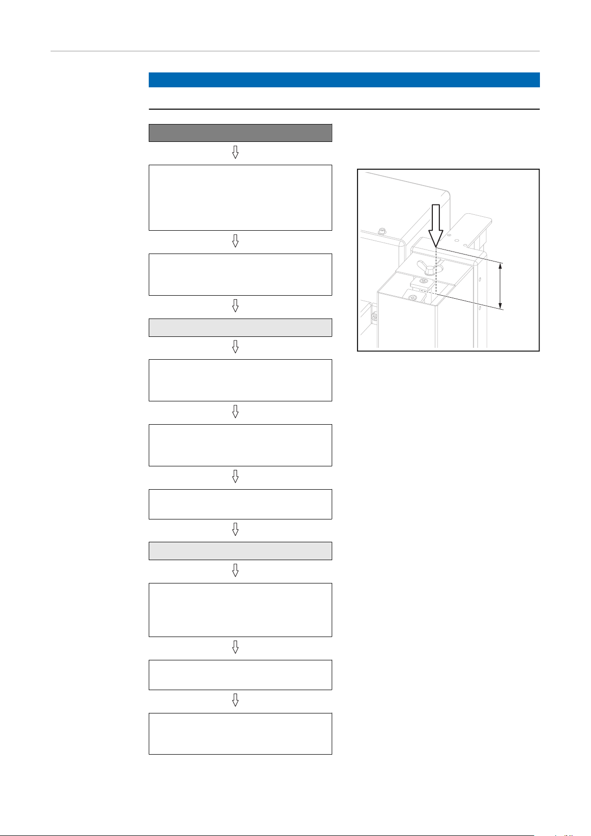
0,5-1mm
.02-.04in.
Loosen the Allen screw (2) on the
1
2
2
4
lifting device
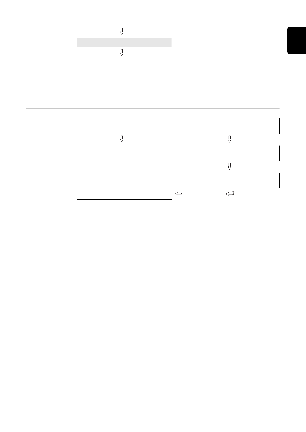
Push the lifting device (3) by hand
5
into its highest lift position and
hold in place
Push the cleaning motor (4) and
6
cleaning cutter by hand into the
cleaning position (5)
NOTE!
The cleaning cutter must not touch
any welding torch components.
Fix the cleaning motor (4) in this
7
position in the lifting device (3) tighten the Allen screw (2) on the
lifting device
8
42

Installing the compressed air supply
EN
Establishing the
compressed air
supply for the
cleaning device,
function of the
compressed air
relief valve
To establish the compressed air supply:
Depressurise the compressed air supply line of the cleaning device and en-
1
sure that it remains depressurised for the duration of the following work on
the device
Screw the supplied compressed air relief valve into the compressed air con-
2
nection on the cleaning device
Connect the compressed air supply line to the compressed air relief valve
3
The compressed air supply to the cleaning device can be broken and re-established by moving the compressed air relief valve forwards and backwards - see
description below.
The diagram below shows the compressed air relief valve in the closed position =
no compressed air supply to the device:
Compressed air relief valve closed
The diagram below shows the compressed air relief valve in the open position =
compressed air is being supplied to the device:
Compressed air relief valve open
43

Starting up the parting agent nebuliser
Fill parting agent
container (1
litre) and connect to the
cleaning device
NOTE!
Only use "Robacta Reamer" parting agent (item number 42,0411,8042) supplied
by the manufacturer.
The composition of the manufacturer's parting agent is designed specifically for
the cleaning device. If other manufacturers' products are used, trouble-free operation cannot be guaranteed.
1 2
3
44

Connect the
222222222
*
2
3
4
1
22
33
11
parting agent
container (10
litres) to the
cleaning device
NOTE!
Only use "Robacta Reamer" parting agent (item number 42,0411,8042) supplied
by the manufacturer.
The composition of this parting agent is designed specifically for the cleaning
device. If other manufacturers' products are used, trouble-free operation cannot
be guaranteed.
EN
1
3
2
* Option (long parting agent hose)
45

Adjusting the
1
-
+
parting agent
nebuliser spray
amount
NOTE!
To ensure that the spray amount is adjusted properly, the welding torch must be
in the cleaning position.
Establish a compressed air supply to the cleaning device
1
Connect the cleaning device to the robot control
2
Start the spraying process using the robot control and check that sufficient
3
spray is being applied
If the spray amount is not sufficient, increase it as required
4
by adjusting the spray time using the robot control - a spray time of ~ 0.7
-
seconds is recommended (nur Robacta Reamer V only)
or by using the parting agent adjuster - see figure below
-
Finely adjusting the spray amount on parting agent adjuster
46

Using the fill-level control sensor
(1)
(2)
(3)
57
15 3,2
4,2
28
36
13
24
3,2
mm
2.24
0.59 0.13
0.17
1.10
1.42
0.51
0.94
0.13
inch
EN
Optional filllevel control
sensor
Controls and indicators on the
sensor
NOTE!
The fill-level control sensor is only available as an option.
The fill-level control sensor emits a signal once the fill level in the parting agent
container falls below a specified level.
(1) 'OUT OFF' button
for programming the sensor
(2) 'OUT ON' button
for programming the sensor
(3) LED
indicates the sensor operating
status
LED on/flashing: sensor is
-
active
LED on/not flashing: sensor
-
is not active
Installation adapter borehole
dimensions
47
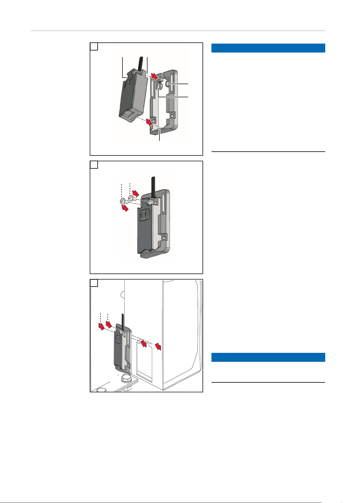
Fitting the fill-
(3)
(1)
(2)
(1)
(2)
1
2
**
1
2
****
1
1
1
1
level control
sensor
1
NOTE!
First press the upper part of the
sensor into the installation adapter as
shown - the sockets (1) on the installation adapter must fit into the recesses
(2) in the sensor.
When the upper part of the sensor is
properly lined up in the installation adapter, press the sensor fully into the
installation adapter - the latch (3) on
the installation adapter must snap
back over the sensor (sensor audibly
engages).
2
* Use the fixings supplied with
the sensor.
3
Screw the installation adapter and
sensor on to the parting agent container housing
** Fixings are not included in the
sensor/installation adapter
scope of supply. The installer is
responsible for selecting the
right type of fixing.
NOTE!
Ensure the fixings do not damage the
parting agent container.
48
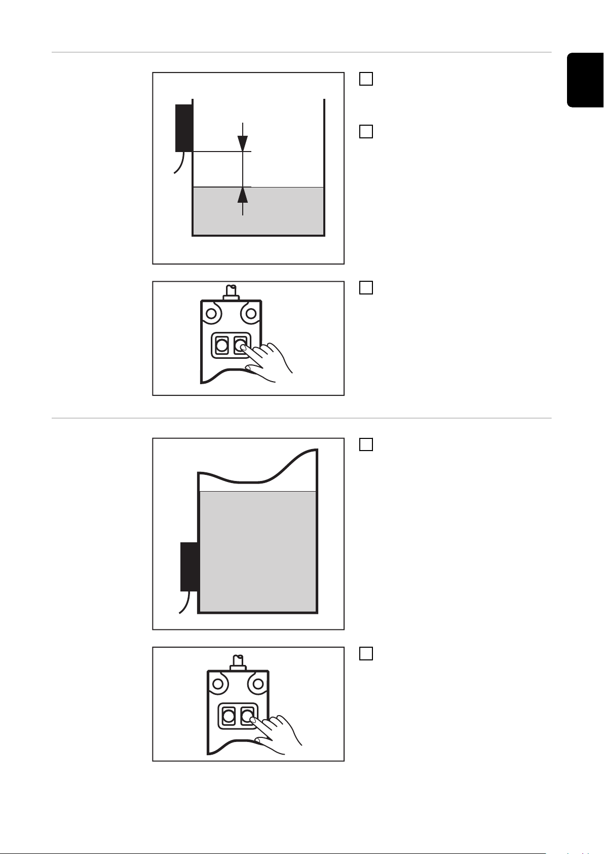
Calibrating the
20 mm (0.79 in.)
2 - 6 s
> 6 s
empty state
Drain the parting agent container
1
until the parting agent level is at
least 20 mm (0.787 in.) below the
sensor
Establish a power supply to the
2
sensor
Press the "OUT OFF" button for
3
between 2 and 6 seconds
The LED on the sensor flashes
-
slowly
After releasing the "OUT OFF"
-
button the LED goes out - the
sensor has detected a low fluid
level
EN
Calibrating the
full state
Fill the parting agent container
1
with parting agent
Press the "OUT OFF" button for at
2
least 6 seconds
The sensor LED flashes slowly
-
at first, then more rapidly after
6 seconds
After releasing the "OUT OFF"
-
button the LED goes out - the
sensor has detected a high flu-
id level
49
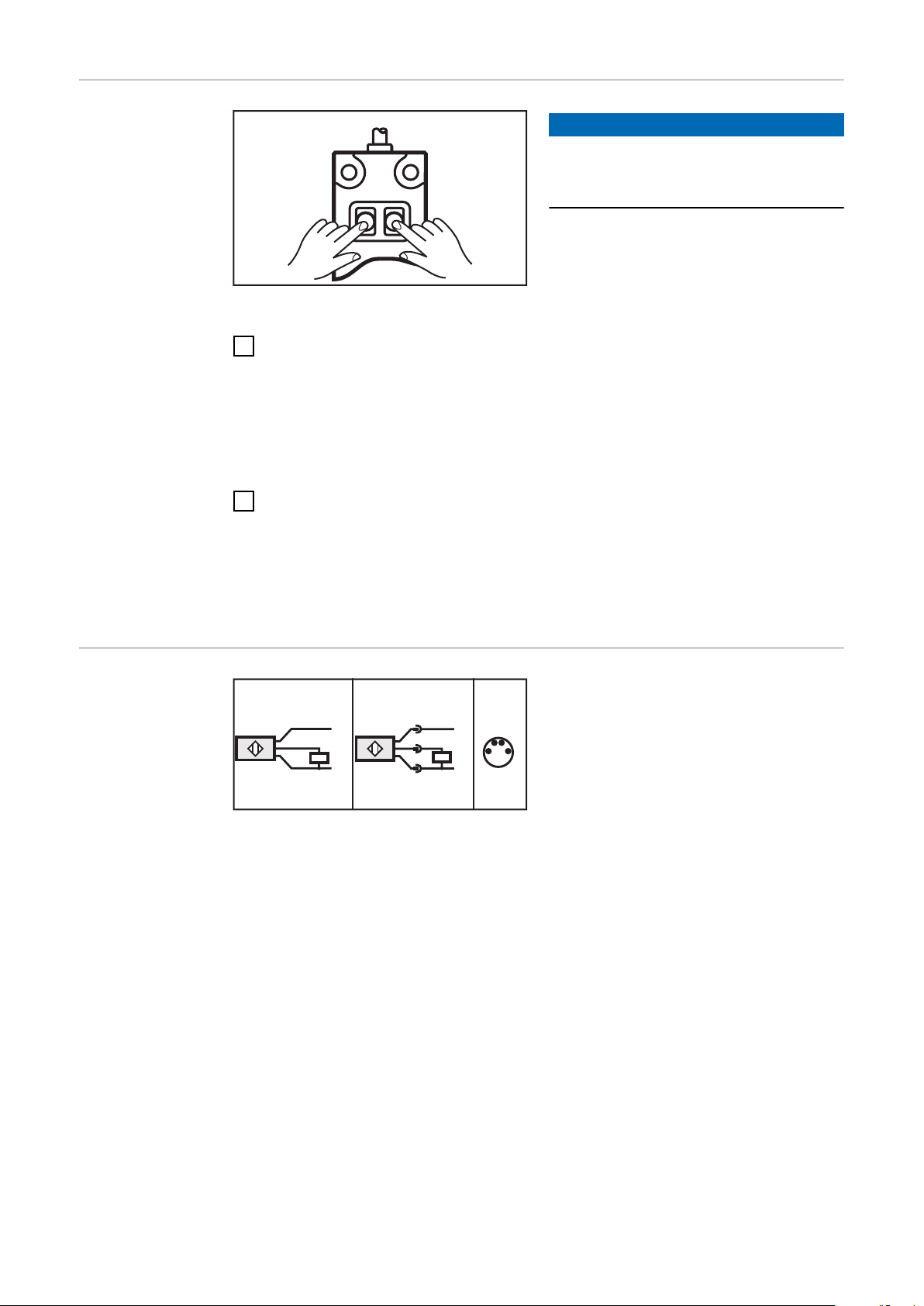
Locking/unlock-
10 s
10 s
1
1
2
3
3
4
4
1
3
4
L-
L+
L-
L+
ing the fill-level
control sensor
NOTE!
It is possible to lock the fill-level control sensor to prevent it from being
adjusted accidentally.
Locking the fill-level control sensor:
Simultaneously press the "OUT OFF" and "OUT ON" buttons for at least 10
1
seconds
The LED status changes briefly
-
if the LED lights up when locking, it will go out briefly after locking
-
if the LED does not light up when locking, it will come on briefly after
-
locking
Unlocking the fill-level control sensor:
Simultaneously press the "OUT OFF" and "OUT ON" buttons for at least 10
1
seconds
The LED status changes briefly
-
if the LED lights up when unlocking, it will go out briefly after unlock-
-
ing
if the LED does not light up when unlocking, it will come on briefly
-
after unlocking
Electrical connection
Wire colours:
1. brown
3. blue
4. black
50
Manually checking the cleaning device functions
0
1
2
1
1
EN
Safety
Checking functions manually
WARNING!
For the following tasks, the cleaning device must be supplied with compressed
air. This results in danger from the rotating cleaning cutter, cleaning motor moving up/down, gas nozzle clamping device moving out/in, flying parts (chips,
etc.), compressed air/parting agent mixture escaping from the parting-agent injection nozzle.
This can result in serious injury and damage to property.
Keep your body, especially your hands, face, hair, any objects and all clothing
▶
awayfrom the cleaning cutter, cleaning motor, lifting device, gas nozzle
clamping device,wire cutter and parting-agent injection nozzle..
Wear ear protection!
▶
Wear protective goggles with side protection.
▶
NOTE!
When the slot for the "Lifting device up/down", "Spray in parting agent" and
"Clamp gas nozzle/Cleaning motor on" screws is positioned horizontally, function is deactivated.
Disconnect the cleaning device from the robot control
1
Establish a compressed air supply to the cleaning device
2
The following must be checked when the functions are being performed:
function of the gas nozzle clamping device (gas nozzle clamping device ex-
-
tends/retracts)
function of the cleaning motor (cleaning motor OFF/ON)
-
3
Clamp gas nozzle/cleaning motor on
The following must be checked when the function is being performed:
how far the cleaning cutter is inserted in the gas nozzle (lifting device moves
-
up/down)
4
Deactivating the functions
51
0
1
2
1
5
1
0
1
2
1
1
6
Lifting device up/down
Deactivating the function
The following must be checked when the function is being performed:
parting agent exit (parting agent is sprayed in)
-
7
Spraying in parting agent
8
Deactivating the function
52

Starting up the cleaning device
EN
Prerequisites for
start-up
Start-up The cleaning device starts up when there is an active signal from the robot con-
The following requirements must be met before the cleaning device is started up:
Cleaning device is bolted to underlying surface
-
Cleaning cutter is fitted
-
Lifting device has been adjusted
-
Parting agent nebuliser has been started up
-
Compressed air supply has been established
-
Functions have been checked manually
-
Cleaning device connected to robot control
-
trol.
53

Cleaning programme
Safety
CAUTION!
Danger due to improper installation and commissioning.
This can result in damage to property.
The cleaning device's functions must be manually checked before starting
▶
automatic operation.
Do not start in automated mode until the cleaning device has been properly
▶
installed and started up.
NOTE!
Not coating the interior of the welding torch may result in permanent soiling of
the torch when welding begins.
Always wet the interior of the welding torch with the manufacturer's parting
▶
agent before starting automatic operation.
54
Cleaning pro-
A
B
50 mm
1.97 in.
50 mm
1.97 in.
gram sequence overview
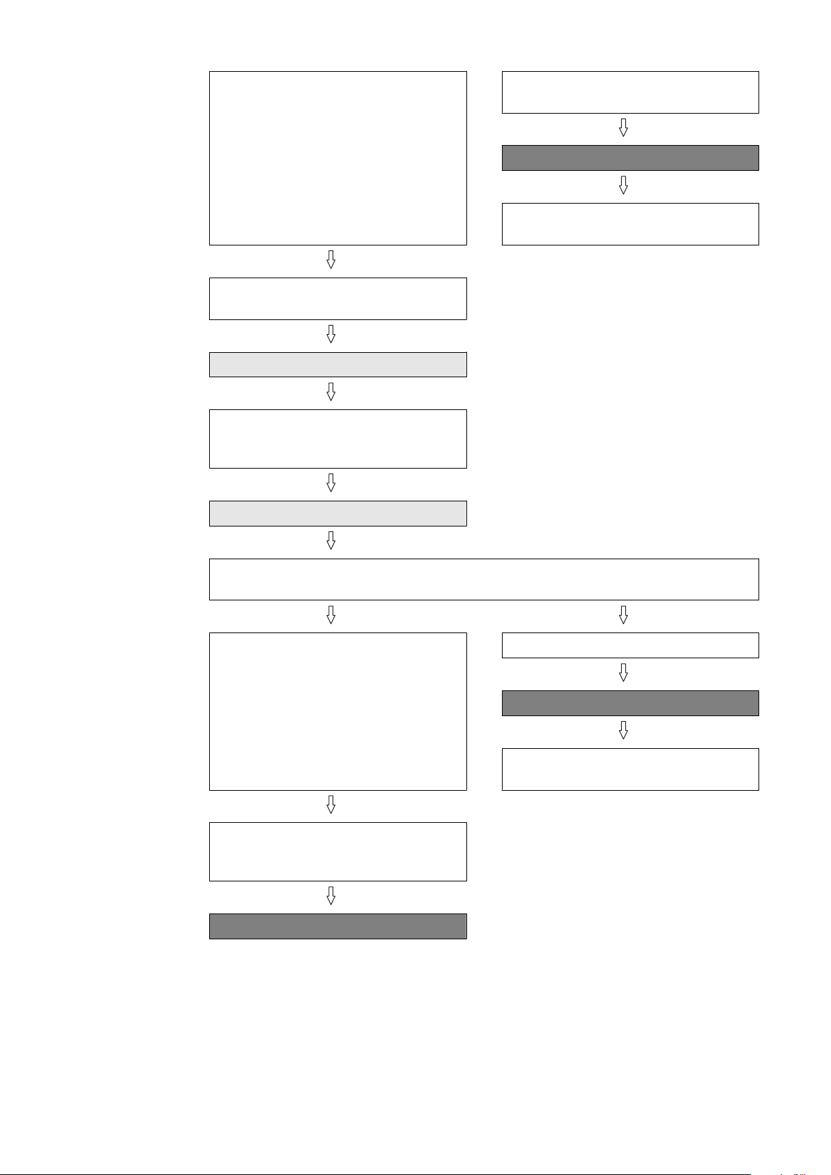
NOTE!
Run through a complete cleaning process each time you start to weld.
The cleaning program sequence is composed of the following sub-processes:
Wire cutter - pos. A
1.
"Parting agent level" query (option)
2.
"Cleaning motor lowered" query
3.
"Gas nozzle free" query
4.
Cleaning - pos. B
5.
EN
Pos. A = wire cutter, pos. B = cleaning
55
1. Wire cutter
A
50 mm
1.97 in.
NOTE!
Perform a complete cleaning cycle each time you start to weld.
Start
Start from position A
approx. 50 mm / 1.97 in. above wire
cutter (between the blades and the
metal cover)
Speed: high speed mode
Set
Signal to the power source "Start
wirefeeding"
Wait approx. 0.5 sec.
Reset
Signal to the power source "Start
wirefeeding"
Insert wire electrode into wire cutter blade
Speed: 50 cm/min / 19.69 ipm
Set
External signal "Cut wire electrode"
Wait 0.5 sec.
Move straight up
approx. 50 mm / 1.97 in. above the
wire cutter blades
Speed: 50 cm/min / 19.69 ipm
Reset
External signal "Cut wire electrode"
56
Set
Signal to the power source "Retract
wire electrode"
2. "Parting agent
level" query (option)
Wait approx. 2 - 3 sec.
Reset
Signal to the power source "Retract
wire electrode"
Next program step:
2. "Parting agent level" query (option)
"Parting agent level OK" query:
Low or High
"Parting agent level OK" query =
High
"Parting agent level OK" query =
Low
Error message:
Refill parting agent
EN
Next program step:
3. "Cleaning motor lowered" query
57

3. "Cleaning motor lowered"
query
"Cleaning motor lowered" query:
Low or High
"Cleaning motor lowered" query =
Low
Set
External signal "Cleaning motor up"
"Cleaning motor lowered" query =
High
Next program step:
4. "Gas nozzle free" query
Reset
External signal "Cleaning motor up"
"Cleaning motor lowered" query:
Low or High
"Cleaning motor lowered" query =
Low
Error message:
Cleaning motor not lowered
Wait 0.5 seconds
Stop
58

4. "Gas nozzle
free" query
"Gas nozzle free" query:
Low or High
"Gas nozzle free" query = Low
Set
External signal "Clamp gas nozzle,
cleaning motor on"
EN
"Gas nozzle free" query = High
Next program step:
5. Cleaning
Reset
External signal "Clamp gas nozzle,
cleaning motor on"
"Gas nozzle free" query:
Low or High
"Gas nozzle free" query = Low
Error message:
Gas nozzle clamped
Wait 0.5 seconds
Stop
59

5. Cleaning
B
50 mm
1.97 in.
Start from position B
approx. 50 mm / 1.97 in. above gas
nozzle clamping device
Speed: high speed mode
Move into the gas nozzle clamping
device
For details see page 36.
Speed: 10 cm/s (236.22 ipm)
Position the welding torch in the
clamping device:
The gas nozzle must sit on the inside of the holder.
Set
External signal "Clamp gas nozzle,
cleaning motor on"
Wait 0.5 sec.
"Gas nozzle clamped" query:
Low or High
"Gas nozzle clamped" query = High
Set
External signal "Swivel to the right"
Wait 0.5 sec.
"Swivel mechanism right" query:
Low or High
"Gas nozzle clamped" query = Low
Error message:
Gas nozzle not clamped
Stop
60

"Swivel mechanism right" query =
Low
EN
"Swivel mechanism right" query =
High
Set
Signal to the power source "Blow
compressed air through welding
torch"
Set
External signal "Cleaning motor up"
(= start cleaning)
Wait 3 sec.
"Cleaning motor raised" query:
Low or High
Error message:
Swivel mechanism not to the right
Stop
"Cleaning motor raised" query =
High
Reset
External signal "Cleaning motor up"
Reset
Signal to the power source "Blow
compressed air through welding
torch"
Set
External signal "Spray parting
agent"
"Cleaning motor raised" query =
Low
Error message:
Cleaning motor not fully raised
Stop
61

Wait 0.5–0.7 sec.
Reset
External signal "Spray parting
agent"
"Cleaning motor lowered" query:
Low or High
"Cleaning motor lowered" query =
High
Reset
External signal "Swivel to the right"
"Cleaning motor lowered" query =
Low
Error message:
Cleaning motor not fully lowered
Stop
Wait 0.5 sec.
Set
External signal "Swivel to the left"
Wait 0.5 sec.
"Swivel mechanism left" query:
Low or High
"Swivel mechanism left" query =
High
"Swivel mechanism left" query =
Low
Stop
62
Error message:
Swivel mechanism not to the left

Set
Signal to the power source "Blow
compressed air through welding
torch"
EN
Set
External signal "Cleaning motor up"
Wait 3 sec.
"Cleaning motor raised" query:
Low or High
"Cleaning motor raised" query =
High
"Cleaning motor raised" query =
Low
Error message:
Cleaning motor not fully raised
Stop
Reset
External signal "Cleaning motor up"
Reset
Signal to the power source "Blow
compressed air through welding
torch"
Set
External signal "Spray parting
agent"
Wait 0.5–0.7 sec.
Reset
External signal "Spray parting
agent"
"Cleaning motor lowered" query
Low or High
63
"Cleaning motor lowered" query =
Low
"Cleaning motor lowered" query =
High
Reset
External signal "Swivel to the left"
Wait 0.5 sec.
Reset
External signal "Clamp gas nozzle,
cleaning motor on"
Wait 0.5 sec.
Error message:
Cleaning motor not fully lowered
Stop
"Gas nozzle free" query:
Low or High
"Gas nozzle free" query = High
Move out of the gas nozzle clamping device
Speed: 10 cm/s (236.22 ipm)
End
"Gas nozzle free" query = Low
Error message:
Gas nozzle clamped
Stop
64
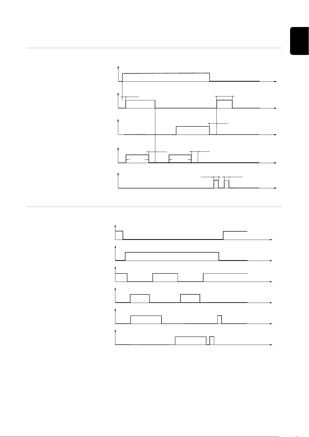
Signal waveform for cleaning
0,5 s
2,0 s
ca. 3 s
ca. 3 s
1,5 s
2,0 s
0,7 s
0,7 s
0,5 s
1.
2.
3.
4.
5.
Signal inputs
1. Gas nozzle clamped:
2. Move swivel mechanism to the
right:
3. Move swivel mechanism to the
left:
4. Cleaning motor up:
5. Spray parting agent:
EN
Signal outputs
Gas nozzle free:
Gas nozzle clamped:
Cleaning motor lowered:
Cleaning motor raised:
Swivel mechanism right:
Swivel mechanism left:
65

Signals not
defined using
time
Parting agent level OK:
Signal waveform:
wire cutter (inputs and outputs)
Cut wire electrode input signal:
66

Care, maintenance and disposal
67

68

Safety
Safety Observe the following safety rules for all work described in the "Care, mainten-
ance and disposal" section.
WARNING!
Danger due to incorrect operation and incorrectly performed work.
This can result in serious injury and damage to property.
All activities described in these Operating Instructions may only be carried
▶
out by trained and qualified personnel.
All functions described in these Operating Instructions may only be used by
▶
trained and qualified personnel.
Do not carry out any of the work or use any of the functions described until
▶
you have fully read and understood the following documents:
these Operating Instructions,
all the Operating Instructions for the system components, especially the
safety rules.
WARNING!
EN
Risk of machines starting automatically!
This can result in serious injury and damage to property.
In addition to these Operating Instructions, also observe the safety rules is-
▶
sued by the manufacturer of the robot and welding system.
Ensure that all protective measures have been taken and will remain in place
▶
while you are in the working area of the robot.
WARNING!
Danger from mechanically powered parts, flying parts (shavings, etc.) and compressed air/parting agent mixture escaping from the parting-agent injection
nozzle.
This can result in severe injuries.
Before carrying out any work on the cleaning device or the connected system
▶
components, disconnect the customer's compressed air and power supplies
from the cleaning device and the connected system components, and ensure
that they remain disconnected until all work is complete.
IMPORTANT! Observe the "Ensuring that the cleaning device is depressurised"
section - see page 30.
69

WARNING!
Danger from power supply and/or compressed air supply to the cleaning device!
The following conditions can lead to serious injuries:
rotating cleaning cutters
lifting device moving up/down
extending/retracting gas nozzle clamping device
activated wire cutter
flying parts (shavings, etc.)
compressed air/parting agent mixture escaping from the parting-agent injection
nozzle
If work has to be performed on the cleaning device while it is being supplied with
voltage and/or compressed air:
keep your body, especially your hands, face, hair, any objects and all clothing
▶
away from the cleaning cutter, lifting device, gas nozzle clamping device, wire
cutter and parting-agent injection nozzle
Wear ear protection
▶
Wear protective goggles with side protection
▶
CAUTION!
Danger due to cleaning cutter that has become very hot through use.
This can cause burns.
Before handling cleaning cutters, allow cleaning cutter to cool to room tem-
▶
perature (+25 °C, +77 °F).
70

Care, maintenance and disposal
General The cleaning device generally needs no maintenance. However, to keep the clean-
ing device in good working condition for years to come, several points on care
and maintenance must be observed.
EN
Before each
start-up
Daily
Weekly
Check fill level in parting agent container and top up if necessary
-
Check fill level in parting agent spatter tray and empty if necessary
-
Check cleaning cutter for wear and replace if necessary
-
Empty the cleaning device spatter tray
-
If fitted, empty the wire cutter tray
-
Carry out a general visual inspection of the cleaning device and make sure
-
that any damage is repaired immediately (before start-up)
CAUTION!
Danger from cleaning agents containing solvents.
This can result in damage to property.
Only use solvent-free cleaning products on the cleaning device.
▶
Remove parting agent deposits and dirt from device
1
CAUTION!
Danger from cleaning agents containing solvents.
This can result in damage to property.
Only use solvent-free cleaning products on the parting agent container.
▶
Check the parting agent container for soiling and clean if necessary
1
Blow through suction filter in parting agent container using compressed air
2
from the inside outwards through the suction hose (for more detailed information see section Starting up the parting agent nebuliser from page 44)
Every 6 months
As necessary Open the device and
Open the device and check the pneumatic valves for
1
Leaks
-
The secure seating of all screws
-
The secure seating of all screw joints on the pneumatic valves
-
Clean inside of device using dry reduced compressed air
1
Lightly oil the lifting device cylinder guides
2
Restore the original condition of the device
3
71

Disposal Dispose of in accordance with the applicable national and local regulations.
72
Adjust the swivel mechanism stop angle
1
2
1
(1) (1)
(1)
(1)
General To make it easier to adjust the stop angle, it is advisable to fit one of the following
adjustment aids to the torch neck:
Robacta Twin 500 adjustment aid, item no. 42,0001,5559
-
Robacta Twin 900 adjustment aid, item no. 42,0001,5560
-
EN
Preparatory
work
Move the welding torch to the cleaning position
1
2
3
4
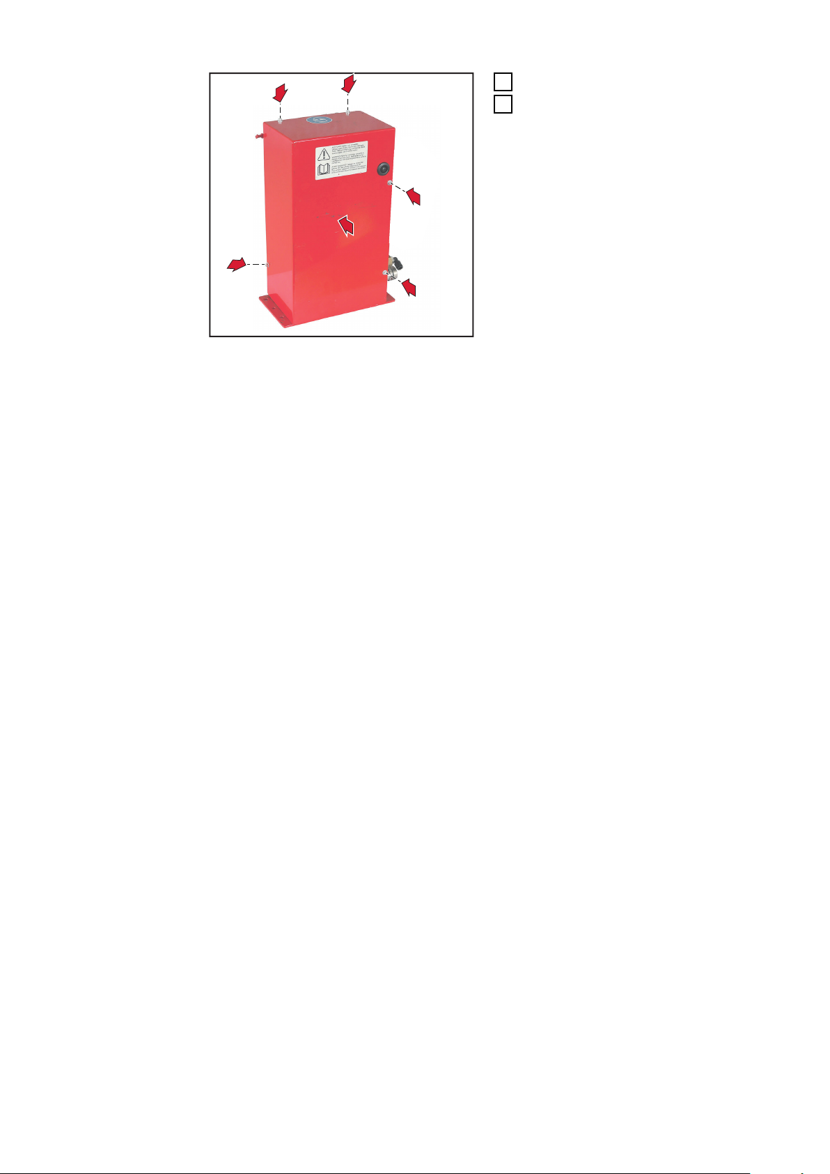
Undo the four Allen screws (1)
Remove cleaning device housing
cover
73

Adjust the swivel
(2)
(3)
(5)
(4)
2-3mm
0.08-0.12in
0,5-1mm
0.02-0.004in
mechanism stop
angle
Banking screw (4) adjusts the left stop angle
-
Banking screw (5) adjusts the right stop angle
-
Undo nut (2) or (3) depending on
1
the stop angle to be adjusted
Depending on the stop angle to be
2
adjusted, undo banking screw (4)
or (5) until the cleaning motor can
be moved to the highest position
where it is not in contact with the
welding torch parts
Manually tilt the cleaning motor to the side to be adjusted and move to the
3
highest position
Adjust the respective banking screw so that the cleaning cutter cannot col-
4
lide with a contact tip or a gas nozzle
Return the cleaning motor to the lowest position
5
Secure the banking screw using the nut (2) or (3) undone previously
6
Manually move the cleaning motor
7
to the highest position
Manually tilt the cleaning motor to
8
the left and right
the cleaning cutter must not
-
collide with the contact tips or
gas nozzle
If the cleaning cutter touches
9
welding torch components, adjust
the stop angle again
74

And finally...
(1) (1)
(1)
(1)
1
2
2
Screw on the cleaning device hous-
1
ing cover using the four original
EN
screws and washers (1)
2
75

76

Troubleshooting
77

78

Safety
Safety Observe the following safety rules for all work described in the "Troubleshooting"
section.
WARNING!
Danger due to incorrect operation and incorrectly performed work.
This can result in serious injury and damage to property.
All activities described in these Operating Instructions may only be carried
▶
out by trained and qualified personnel.
All functions described in these Operating Instructions may only be used by
▶
trained and qualified personnel.
Do not carry out any of the work or use any of the functions described until
▶
you have fully read and understood the following documents:
these Operating Instructions,
all the Operating Instructions for the system components, especially the
safety rules.
WARNING!
EN
Risk of machines starting automatically!
This can result in serious injury and damage to property.
In addition to these Operating Instructions, also observe the safety rules is-
▶
sued by the manufacturer of the robot and welding system.
Ensure that all protective measures have been taken and will remain in place
▶
while you are in the working area of the robot.
WARNING!
Danger from mechanically powered parts, flying parts (shavings, etc.) and compressed air/parting agent mixture escaping from the parting-agent injection
nozzle.
This can result in severe injuries.
Before carrying out any work on the cleaning device or the connected system
▶
components, disconnect the customer's compressed air and power supplies
from the cleaning device and the connected system components, and ensure
that they remain disconnected until all work is complete.
IMPORTANT! Observe the "Ensuring that the cleaning device is depressurised"
section - see page 30.
79

WARNING!
Danger from power supply and/or compressed air supply to the cleaning device!
The following conditions can lead to serious injuries:
rotating cleaning cutters
lifting device moving up/down
extending/retracting gas nozzle clamping device
activated wire cutter
flying parts (shavings, etc.)
compressed air/parting agent mixture escaping from the parting-agent injection
nozzle
If work has to be performed on the cleaning device while it is being supplied with
voltage and/or compressed air:
keep your body, especially your hands, face, hair, any objects and all clothing
▶
away from the cleaning cutter, lifting device, gas nozzle clamping device, wire
cutter and parting-agent injection nozzle
Wear ear protection
▶
Wear protective goggles with side protection
▶
CAUTION!
Danger due to cleaning cutter that has become very hot through use.
This can cause burns.
Before handling cleaning cutters, allow cleaning cutter to cool to room tem-
▶
perature (+25 °C, +77 °F).
80

Troubleshooting
EN
Errors in program sequence
The parting agent does not spray
Parting agent container is full
Cause:
Remedy:
Cause:
Remedy:
Cause:
Remedy:
Cause:
Remedy:
Cause:
Remedy:
Not enough spray
Adjust spray time
Parting agent hose suction filter in the parting agent container is
soiled
Clean the suction filter of the parting agent hose with compressed air
(for more detailed information, see section Starting up the parting
agent nebuliser from page 44)
No signal from robot
Check robot program
Parting-agent injection nozzle blocked
Clean parting-agent injection nozzle
Contact After-Sales Service (arrange for parting-agent injection
nozzle to be replaced)
Vacuum pump faulty
Contact After-Sales Service (arrange for vacuum pump to be re-
placed)
Cause:
Remedy:
Welding torch is poorly cleaned or damaged
Cause:
Remedy:
Cause:
Remedy:
Cause:
Remedy:
Mechanical fault on solenoid valve
Contact After-Sales Service (arrange for solenoid valve to be re-
placed)
Lifting device not adjusted properly
Adjust the lifting device
Cleaning cutter not suited to welding torch shape
Fit the correct cleaning cutter
Cleaning cutter is worn
Replace cleaning cutter
81

Cleaning cutter collides with a contact tip or gas nozzle
Cause:
Remedy:
Lifting device not adjusted properly
Adjust the lifting device
Cause:
Remedy:
Cause:
Remedy:
Cause:
Remedy:
Lifting device is not moving up or down
Cause:
Remedy:
Cause:
Remedy:
Cause:
Remedy:
Cause:
Remedy:
Cleaning cutter not suited to welding torch shape
Fit the correct cleaning cutter
Cleaning cutter is worn
Replace cleaning cutter
Incorrect swivel mechanism stop angle
Adjust the swivel mechanism stop angle
No compressed air supply
Establish a compressed air supply
No signal from robot
Check robot program
Mechanical fault on solenoid valve
Contact After-Sales Service (arrange for solenoid valve to be re-
placed)
Choke valve not adjustable, or faulty
Contact After-Sales Service (arrange for choke valve to be replaced)
Cause:
Remedy:
Cleaning motor does not work
Cause:
Remedy:
Cause:
Remedy:
Cause:
Remedy:
Cause:
Remedy:
Faulty sealing in lifting cylinder
Contact After-Sales Service (arrange for lifting cylinder to be re-
placed)
No compressed air supply
Establish a compressed air supply
No signal from robot
Check robot program
Mechanical fault on cleaning motor
Contact After-Sales Service (arrange for cleaning motor to be re-
placed)
Mechanical fault on solenoid valve
Contact After-Sales Service (arrange for solenoid valve to be re-
placed)
82

Technical data
83

84

Technical data
EN
Robacta Reamer
V Twin
Supply voltage + 24 V DC
Rated power 14.4 W
Nominal pressure 6 bar
86.99 psi
Air consumption 440 l/min
465 qt./min
Compressed air connection thread
identification
Standard I/O (X1) Input: + 24 V DC / max. 300 mA
Output: + 24 V DC / max. 30 mA
Cleaning time 7.0 - 7.5 s
Total cycle time 8.5 - 10 s
Parting agent container capacity 1 l
0.26 gal. (US)
Protection class IP 21
Mark of conformity CE, CSA
Safety symbols S
'Performance Level' c
G ¼"
Max. noise emission (LWA) 82 dB (A)
Dimensions L x W x H 225 x 400 x 380 mm
8.86 x 15.75 x 14.96 in.
Weight
(without parting agent)
17 kg
37.48 lb.
85

86

Appendix
87

88
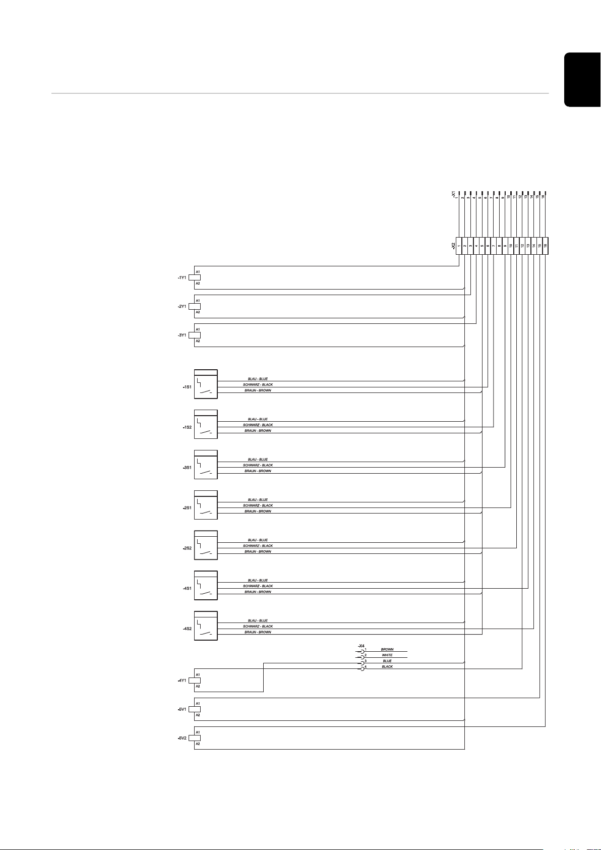
Circuit diagram Robacta Reamer V Twin
GASDÜSE SPANNEN UND REINIGUNGSMOTOR EIN
CLAMP GAS NOZZLE AND CLEANING MOTOR ON
SCHWENKVORRICHTUNG NACH LINKS
MOVE SWIVEL MECHANISM TO THE LEFT
SCHWENKVORRICHTUNG NACH RECHTS
MOVE SWIVEL MECHANISM TO THE RIGHT
SCHWENKVORRICHTUNG LINKS
SWIVEL MECHANISM LEFT
SCHWENKVORRICHTUNG RECHTS
SWIVEL MECHANISM RIGHT
REINIGUNGSMOTOR OBEN
CLEANING MOTOR RAISED
REINIGUNGSMOTOR UNTEN
NICHT BELEGT
NOT ASSIGNED
CLEANING MOTOR LOWERED
REINIGUNGSMOTOR AUF
CLEANING MOTOR UP
Gasdüse spannen und Reinigungsmotor ein
Clamp gas nozzle and Cleaning motor on
Reinigungsmotor auf
Cleaning motor up
Trennmittel einsprühen
Spray parting agent
Reinigungsmotor unten
Cleaning motor lowered
Trennmittel-Stand I.O
Parting agent level OK
Gasdüse gespannt
Gas nozzle clamped
Gasdüse frei
Gas nozzle free
Reinigungsmotor oben
Cleaning motor raised
Schwenkvorrichtung nach rechts
Move swivel mechanism to the right
Schwenkvorrichtung nach links
Move swivel mechanism to the left
Drahtelektrode abschneiden
Cut wire
Schwenkvorrichtung rechts
Swivel mechanism right
Schwenkvorrichtung links
Swivel mechanism left
GND (ALLGEMEIN)
GND (GENERAL)
+24 V DC
TRENNMITTEL EINSPRÜHEN
SPRAY PARTING AGENT
GASDÜSE FREI
GAS NOZZLE FREE
GASDÜSE GESPANNT
GAS NOZZLE CLAMPED
TRENNMITTEL-STAND I.O.
PARTING AGENT LEVEL OK
DRAHTELEKTRODE ABSCHNEIDEN
CUT WIRE
EN
89

Robacta Reamer V Twin pneumatic diagram
GASDÜSE SPANNEN UND REINIGUNGSMOTOR EIN
CLAMP GAS NOZZLE AND CLEANING MOTOR ON
REINIGUNGSMOTOR AUF
CLEANING MOTOR UP
TRENNMITTEL EINSPRÜHEN
SPRAY PARTING AGENT
DRAHTELEKTRODE ABSCHNEIDEN
CUT WIRE
SCHWENKVORRICHTUNG
NACH LINKS / RECHTS
MOVE SWIVEL MECHANISM
TO THE LEFT / RIGHT
6 bar (86.99 psi) GEFILTERTE DRUCKLUFT
6 bar (86.99 psi) FILTERED COMPRESSED AIR
Anschluss Druckluft 1/4 inch
Druckluft-Entlastungsventil 3/2
compressed air relief valve 3/2
solenoid valve 3/2
gas nozzle clamping device
cleaning motor
solenoid valve 5/2
choke check valve
solenoid valve 3/2
choke valve
check valve
wire cutter
solenoid valve 3/2
swivel mechanism for cleaning motor
solenoid valve 5/2
Magnetventil 3/2
Spannvorrichtung Gasdüse
Reinigungsmotor
Magnetventil 5/2
Drosselrückschlagventil
Magnetventil 3/2
Drosselventil
Rückschlagventil
Filter
Vakuumpumpen-Düse Ø 0,8 mm (0.031 inch)
Magnetventil 3/2
Schwenkvorrichtung für Reinigungsmotor
Magnetventil 5/2
Trennmittel-Einsprühdüse Ø 1,6 mm (0.063 inch)
vacuum pump choke Ø 0,8 mm (0.031 inch)
filter
parting agent injection nozzle Ø 1,6 mm (0.063 inch)
Drahtabschneider
Hubvorrichtung mit Motorhalterung
lifting device with motor bracket
compressed air connection 1/4 inch
90

Declaration of conformity
DE German Deutsch EN English English FR French Française
EU-KONFORMITÄTSERKLÄRUNG 2016
EU-DECLARATION OF CONFORMITY 2016
DÉCLARATION UE DE CONFORMITÉ, 2016
Wels-Thalheim, 2016-07-07
eingapmoc aLrerutcafunaMamriF eiD
FRONIUS INTERNATIONAL GMBH
Froniusstaße 1, A-4643 Pettenbach
erklärt in alleiniger Verantwortung,
dass folgendes Produkt:
Robacta Reamer V Twin
Gasdüsenreinigungsgerät
auf das sich diese Erklärung
bezieht, mit folgenden Richtlinien
bzw. Normen übereinstimmt:
Richtlinie 2014/30/EU
Elektromag. Verträglichkeit
Richtlinie 2006/42/EG
Maschinenrichtlinie
Europäische Normen inklusive
zutreffende Änderungen
EN ISO 12100:2010
EN 61000-6-2:2005+AC:2005
EN 61000-6-4:2007+A1:2011
Die oben genannte Firma hält
Dokumentationen als Nachweis der
Erfüllung der Sicherheitsziele und
die wesentlichen Schutzanforderungen zur Einsicht bereit.
Dokumentationsverantwortlicher:
(technische Dokumentation)
Ing. Josef Fe
ichtinger
Günter Fronius Straße 1
A - 4600 Wels-Thalheim
Hereby certifies on its sole
responsibility that the following
product:
Robacta Reamer V Twin
Gas nozzle cleaner
which is explicitly referred to by this
Declaration meet the following
directives and standard(s):
Directive 2014/30/EU
Electromag. compatibility
Directive 2006/42/EC
Machinery Directive
European Standards including
relevant amendments
EN ISO 12100:2010
EN 61000-6-2:2005+AC:2005
EN 61000-6-4:2007+A1:2011
Documentation evidencing
conformity with the requirements of
the Directives is kept available for
inspection at the above
Manufacturer.
person responsible for documents:
(technical documents)
Ing. Josef Feichtinger
Günter Fronius Straße 1
A - 4600 Wels-Thalheim
se déclare seule responsable du fait
que le produit suivant:
Robacta Reamer V Twin
Appareil de nettoyage de buses gaz
qui est l’objet de la présente
déclaration correspondent aux
suivantes directives et normes:
Directive 2014/30/UE
Électromag. Compatibilité
Directive 2006/42/CE
Directive aux machines
Normes européennes avec
amendements correspondants
EN ISO 12100:2010
EN 61000-6-2:2005+AC:2005
EN 61000-6-4:2007+A1:2011
En tant que preuve de la satisfactio
n
des demandes de sécurité la
documentation peut être consultée
chez la compagnie susmentionnée.
responsable documentation:
(technique documentation)
Ing. Josef Feichtinger
Günter Fronius Straße 1
A - 4600 Wels-Thalheim
2016 ppa. Mag.Ing.H.Hackl
Member of Board
Chief Technology Officer
EN
91

 Loading...