

Operating
Instructions
Robacta Reamer Braze+
EN-US
Operating instructions
42,0426,0281,EA 009-27012023


Table of contents
Safety Instructions 5
Explanation of Safety Instructions 5
General 5
Intended Use 6
Environmental Conditions 6
Obligations of the Operating Company 6
Obligations of Personnel 6
Particular Hazard Areas 6
Personal Protection and Protection of Others 7
EMC Device Classifications 7
EMC Measures 8
EMF measures 8
Safety Measures at the Setup Location and during Transport 8
Safety measures in normal operation 9
Maintenance and repair 9
Safety Inspection 9
Disposal 9
Safety Symbols 10
Copyright 10
General 11
Warning notices affixed to the device 13
Warning Notices on the Cleaning Device 13
Transport 15
Transport equipment 15
Transport Instructions on the packaging 15
Information about Unpacking the Device 15
Scope of Supply 17
Scope of Supply 17
Available Options 17
EN-US
Operating controls, connections and mechanical components 19
Safety 21
Safety 21
Operating controls, connections and mechanical components 22
Operating controls, connections, and mechanical components 22
Harting Han6P (X1) Connecting Plug Configuration for the Robot Control 23
General 23
Harting Han6P (X1) Connecting Plug Configuration 23
Installation and Startup 25
Safety 27
Safety 27
Before installation 28
Intended Use 28
Operating personnel, maintenance personnel 28
Setup regulations 28
Specifications for the compressed air supply 28
Measures to ensure safe operation of the device when operating personnel are untrained 29
Permitted Cable Length 29
Screwing the Cleaning Device to the Solid Surface 30
Screwing the cleaning device to the surface 30
Installation of optional wire cutter 31
Assignment of the connecting plug 31
Installing the wire cutter 31
Setting up the Compressed Air Supply 33
Setting up the cleaning device compressed air supply, compressed air relief valve function 33
Cleaning the Cleaning Head 34
3

Installing the cleaning head 34
Defining the Welding Torch Cleaning Position 36
Welding torch cleaning position 36
Start up the Cleaning Device 40
Requirements for Starting Up 40
Commissioning 40
Cleaning Program Sequence 41
Safety 41
Cleaning Program Sequence 42
Signal Sequences 45
Signal Sequences 45
Service, maintenance and disposal 47
Safety 49
Safety 49
Service, maintenance and disposal 50
General 50
Before Every Start-up 50
Weekly 50
Every 6 months 50
Whenever Required 50
Changing the Cleaning Blades 50
Changing the Cleaning Brushes 55
Disposal 58
Troubleshooting 59
Safety 61
Safety 61
Troubleshooting 62
Errors in the Program Sequence 62
Technical data 63
Technical data 65
Robacta Reamer Braze+ 65
Appendix 67
Declaration of conformity 69
4

Safety Instructions
EN-US
Explanation of
Safety Instructions
DANGER!
Indicates an immediate danger.
Death or serious injury may result if appropriate precautions are not taken.
▶
WARNING!
Indicates a possibly dangerous situation.
Death or serious injury may result if appropriate precautions are not taken.
▶
CAUTION!
Indicates a situation where damage or injury could occur.
Minor injury or damage to property may result if appropriate precautions are
▶
not taken.
NOTE!
Indicates the possibility of flawed results and damage to the equipment.
General The device has been manufactured using state-of-the-art technology and ac-
cording to recognized safety standards. If used incorrectly or misused, however,
it can cause
injury or death to the operator or a third party,
-
damage to the device and other material assets belonging to the operating
-
company,
inefficient operation of the device.
-
All persons involved in the commissioning, operation, maintenance, and servicing
of the device must
be suitably qualified,
-
have knowledge of automated welding and
-
have read these Operating Instructions and any system component operating
-
instructions in full and follow them carefully.
The Operating Instructions must always be at hand wherever the device is being
used. In addition to the Operating Instructions, all applicable local rules and regulations regarding accident prevention and environmental protection must also
be followed.
All safety and danger notices on the device must
must be kept in a legible state
-
not be damaged/marked
-
not be removed
-
not be covered, pasted, or painted over
-
For the location of the safety and danger notices on the device, refer to the section headed "General" in the Operating Instructions for the device.
Before switching on the device, remove any faults that could compromise safety.
Your personal safety is at stake!
5

Intended Use The device is to be used exclusively for its intended purpose.
The device is intended exclusively for the mechanical cleaning of Fronius robot
welding torches in automatic mode.
Utilization for any other purpose, or in any other manner, shall be deemed to be
"not in accordance with the intended purpose." The manufacturer is not responsible for any damage resulting from improper use.
Proper use also means
Reading these Operating Instructions in their entirety
-
Following all instructions and safety rules in these Operating Instructions
-
Carrying out all the specified inspection and servicing work
-
The device is designed for operation in industry and business. The manufacturer
shall not be liable for any damage resulting from use in a living area.
The manufacturer shall also not be liable for faulty or incorrect work results.
Environmental
Conditions
Obligations of
the Operating
Company
Operation or storage of the device outside the stipulated area will be deemed as
not in accordance with the intended purpose. The manufacturer is not responsible for any damage resulting from improper use.
Temperature range of the ambient air:
During operation: 0°C to + 40°C (32°F to 104°F)
-
During transport and storage: -25°C to +55°C (-13°F to 131°F)
-
Relative humidity:
Up to 50% at 40°C (104°F)
-
Up to 90% at 20°C (68°F)
-
Ambient air: free of dust, acids, corrosive gases or substances, etc.
Altitude above sea level: up to 2000 m (6500 ft.)
The operating company must only allow persons to work with the device if they
Are familiar with the basic occupational safety and accident prevention regu-
-
lations and are trained in handling the device
Have read and understood these Operating Instructions, especially the sec-
-
tion "Safety Rules," and have confirmed this with their signature
Are trained according to the requirements for the work results
-
The safety-conscious work of the personnel must be checked regularly.
Obligations of
Personnel
Particular Hazard Areas
6
All persons who are assigned to work with the device must do the following before beginning the work:
Follow the basic regulations for occupational safety and accident prevention
-
Read these Operating Instructions, especially the section "Safety Rules," and
-
confirm that they have understood and will follow them by signing
Before leaving the workplace, ensure that no personal injury or property damage
can occur in one's absence.
Do not linger in the operating area of the robot.

Always integrate the device into a superordinate safety system in a secured area.
If this area has to be accessed for preparatory or maintenance work, ensure that
the entire system is shut down for the duration of access to this area
-
and remains shut down to prevent unintended operation, for example, as a
-
result of a control error.
If untrained operating personnel have access to the device, the compressed air
supply to the device must be disconnected for the duration of this access in accordance with "Performance Level d" of ISO 13849-1.
In addition to these Operating Instructions, the safety rules of the robot manufacturer must be followed.
The human body, and in particular the hands, face and hair, plus items of clothing
and all tools, must be kept away from moving components, such as:
the rotating cleaning head
-
the cleaning head that moves up and down
-
Do not touch the cleaning head immediately after operation – burning hazard.
Follow the special safety rules for handling the cleaning head in the Operating
Instructions.
Protect the hands, face, and eyes from flying parts (chips, etc.).
Covers must only be opened/removed during maintenance, installation and repair work.
EN-US
Personal Protection and Protection of Others
EMC Device
Classifications
During operation:
ensure that all covers are closed and all side parts have been mounted prop-
-
erly,
keep all covers closed.
-
You are exposed to numerous hazards while handling the device. In addition to
these Operating Instructions, the safety rules of the manufacturer of the entire
welding system must be followed.
Keep persons, especially children, away during the operation of the devices and
during the welding process. If persons are in the vicinity, however:
instruct them about all hazards (crush hazard posed by moving mechanical
-
parts, flying chips or similar, injury hazard due to flying sparks, blinding hazard due to arcs, welding fume hazardous to health, noise exposure, possible
hazard due to mains current or welding current, etc.)
provide suitable protective equipment or
-
construct suitable protective walls and curtains.
-
Devices in emission class A:
Are only designed for use in industrial settings
-
Can cause line-bound and radiated interference in other areas
-
Devices in emission class B:
Satisfy the emissions criteria for residential and industrial areas. This is also
-
true for residential areas in which the energy is supplied from the public lowvoltage grid.
EMC device classification as per the rating plate or technical data.
7

EMC Measures In certain cases, even though a device complies with the standard limit values for
emissions, it may affect the application area for which it was designed (e.g., when
there is sensitive equipment at the same location, or if the site where the device
is installed is close to either radio or television receivers).
If this is the case, then the operating company is obliged to take appropriate action to rectify the situation.
Check and evaluate possible problems and the interference immunity of equipment in the vicinity according to national and international regulations:
Safety devices
-
Grid power lines, signal lines, and data transfer lines
-
EMC and telecommunications equipment
-
Devices for measuring and calibrating
-
Supporting measures to avoid EMC problems:
Grid power supply
1.
If electromagnetic interference occurs despite a grid connection that
-
complies with regulations, take additional measures (e.g., use a suitable
grid filter).
Control lines
2.
Keep them as short as possible
-
Route them close together (also to avoid EMF problems)
-
Route them far from other lines
-
Equipotential bonding
3.
Shield, if necessary
4.
Shield other devices in the vicinity
-
Shield the entire welding installation
-
EMF measures Electromagnetic fields may cause health problems that are not yet known:
Effects on the health of persons close by, e.g., those with pacemakers and
-
hearing aids
Persons with pacemakers must seek advice from their doctor before staying
-
in the immediate vicinity of the device and the welding process
Keep distances between welding power-leads and the head/torso of the
-
welder as great as possible for safety reasons
Do not carry welding power-leads and hosepacks over your shoulder or wrap
-
them around your body or body parts
Safety Measures
at the Setup
Location and
during Transport
A toppling device can be deadly! Install the device horizontally on a flat, stable
surface free of vibration, anchor it securely on the surface, and secure against
toppling.
Special regulations apply in areas at risk of fire or explosion
Follow the appropriate national and international regulations.
-
Use instructions and checks within the company to ensure that the vicinity of the
workplace is always clean and organized.
Take care to ensure that the applicable national and regional guidelines and accident prevention regulations are observed when transporting the device, especially guidelines concerning hazards during transport and shipment.
It is essential to conduct a visual inspection of the device to check for damage
after it has been transported but before it is commissioned. Have any damage repaired by trained service technicians before commissioning the device.
8

Safety measures
in normal operation
Only operate the device when all safety devices are fully functional. If the safety
devices are not fully functional, there is a danger of:
Serious or fatal injury to the operator or third parties
-
Damage to the device and other material assets belonging to the operating
-
company
Inefficient operation of the device
-
Safety devices that are not fully functional must be repaired before the device is
switched on.
Never bypass or disable safety devices.
Before switching on the device, ensure that no one can be put in danger.
The device must be examined at least once a week for externally detectable damage and functionality of the safety devices.
EN-US
Maintenance and
repair
Safety Inspection
It is impossible to guarantee that bought-in parts are designed and manufactured to meet the demands made of them, or that they satisfy safety requirements.
Use only original spare and wearing parts (also applies to standard parts).
-
Do not carry out any modifications, alterations, etc. to the device without the
-
manufacturer's consent.
Components that are not in perfect condition must be replaced immediately.
-
When ordering, please give the exact designation and part number as shown
-
in the spare parts list, as well as the serial number of your device.
The housing screws provide the ground conductor connection for earthing the
housing parts.
Only use original housing screws in the correct number and tightened to the specified torque.
The manufacturer recommends that a safety inspection of the device be performed at least every 12 months.
A safety inspection by a certified electrician is recommended:
after changes
-
after alterations
-
after repair, care, and maintenance
-
at least every 12 months.
-
For the safety inspection, follow the appropriate national and international
standards and guidelines.
You can obtain more information about the safety inspection and calibration
from your service center. The service center will provide the necessary documents upon request.
Disposal Waste electrical and electronic equipment must be collected separately and re-
cycled in an environmentally sound manner in accordance with the European Directive and national law. Used equipment must be returned to the distributor or
through a local authorized collection and disposal system. Proper disposal of the
used device promotes sustainable recycling of material resources. Failure to observe this may lead to potential health/environmental impacts.
9

Packaging materials
Separate collection. Check your municipality’s regulations. Reduce the volume of
the box.
Safety Symbols Devices with CE marking satisfy the essential requirements of the relevant dir-
ectives (e.g. the low-voltage, electromagnetic compatibility, and machinery directives).
Devices marked with the CSA test mark satisfy the requirements of the relevant
standards for Canada and the USA.
Copyright Copyright of these Operating Instructions remains with the manufacturer.
Text and illustrations were accurate at the time of printing. Fronius reserves the
right to make changes. The contents of the Operating Instructions shall not
provide the basis for any claims whatsoever on the part of the purchaser. If you
have any suggestions for improvement, or can point out any mistakes that you
have found in the Operating Instructions, we will be most grateful for your comments.
10

General
11

12
Warning notices affixed to the device
EN-US
Warning Notices
on the Cleaning
Device
The cleaning device has warning notices and a rating plate fitted. These warning notices and the rating plate must not be removed or painted over.
Warning notices on the cleaning device
WARNING! Risk of serious injuries due to:
moving mechanical parts
-
flying debris (chips, etc.)
-
During maintenance and service, keep the device de-energized and
depressurized.
Do not use the functions described here until you have fully read
and understood the following documents:
these Operating Instructions
-
all Operating Instructions for system components, especially
-
the safety rules
For indoor use only
Dispose of old devices in accordance with safety rules and not in
normal domestic waste
Wear eye protection
13

Warning before the device switches on automatically
14
Transport
EN-US
Transport equipment
Transport Instructions on the
packaging
Transport the device using the following transport equipment:
On a pallet using a counterbalanced lift truck
-
On a pallet using a lift truck
-
Manually
-
WARNING!
Danger from devices and objects falling.
This can result in severe personal injury and damage to property.
When transporting the device by counterbalanced lift truck or lift truck, se-
▶
cure the device to prevent it from falling.
Do not turn, brake, or accelerate in a sudden, jerking manner.
▶
CAUTION!
Danger due to improper transport.
This can result in damage to property.
Follow the transport instructions on the device packaging.
▶
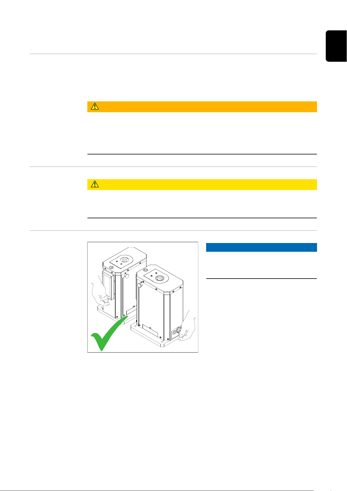
Information
about Unpacking
the Device
NOTE!
When lifting the device out of the
packaging, hold the device in the position shown.
15
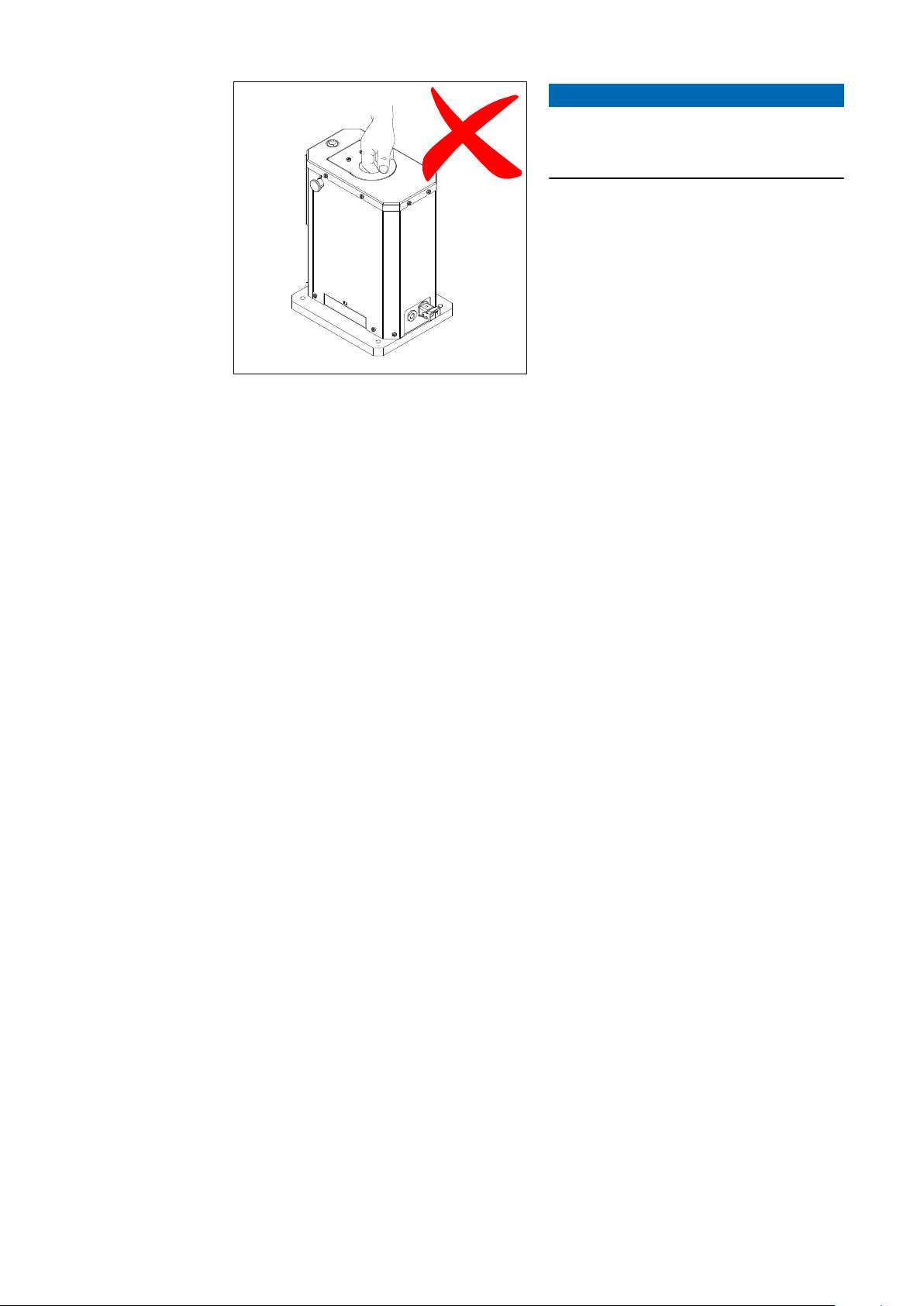
NOTE!
When lifting the device out of the
packaging, do not hold the motor cover to lift it.
16

Scope of Supply
(2)
(1)
EN-US
Scope of Supply
Available Options
(1) Cleaning device
(2) Compressed air relief valve
not shown:
(3) Harting Han6P (X1) connecting
plug without cable
(4) Operating instructions
(1) Teach-gauge
(2) Open collecting container
17

18

Operating controls, connections
and mechanical components
19

20

Safety
Safety Please follow the safety rules below when using all the functions described in the
"Operating controls, connections, and mechanical components" chapter.
WARNING!
Danger from incorrect operation and work that is not carried out properly.
This can result in severe personal injury and damage to property.
All the work and functions described in this document must only be carried
▶
out by trained and qualified personnel.
Read and understand this document.
▶
Read and understand all the Operating Instructions for the system compon-
▶
ents, especially the safety rules.
EN-US
21
Operating controls, connections and mechanical
(1)
(3)
(2)
(4)
(5)
(6)
(7)
components
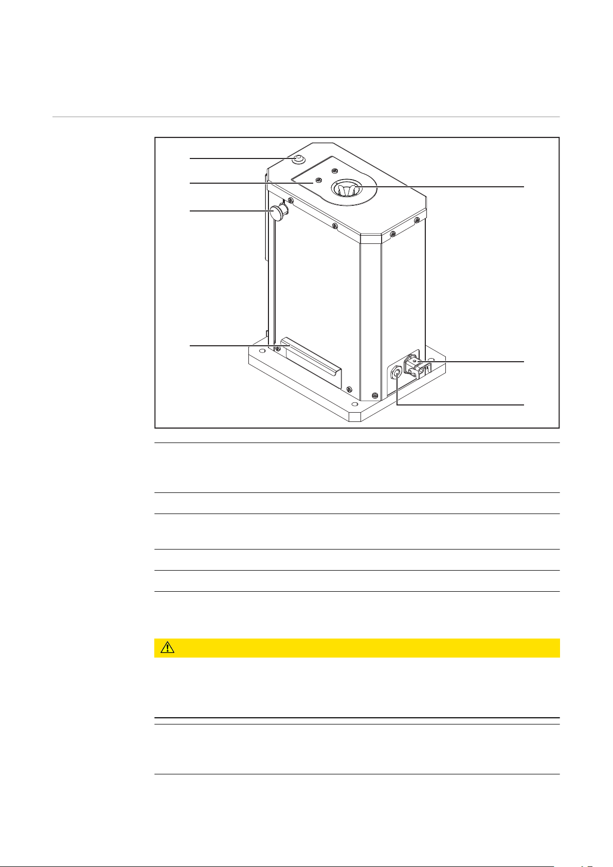
Operating controls, connections, and mechanical components
(1) Status indicator
illuminates when the device is ready for cleaning
-
does not illuminate when there is a fault or the device is in operation
-
(2) Motor cover
(3) Lock bolt for motor cover
locks the motor cover in place (2)
(4) Collecting container
(5) Gas nozzle slot for cleaning head
(6) Harting Han6P (X1) connection socket
+ 24 V DC power supply
CAUTION!
Danger from overcurrent.
Damage to the power supply for the Harting Han6P connection may result.
Fuse the power supply of the cleaning device with 500 mA slow-blow fuse
▶
against overcurrent.
(7) Compressed air connection
supplies 6 bar (86.99 psi) of dry compressed air
Thread identification for compressed air connection: G ¼"
22

Harting Han6P (X1) Connecting Plug Configura-
2
45
3
1
tion for the Robot Control
General
Danger from overcurrent.
Damage to the power supply for the Harting Han6P connection may result.
▶
To avoid interference, keep the line length between the cleaning device and the
robot control as short as possible.
The Harting Han6P (X1) connecting plug for connecting the cleaning device to
the robot control is included in the scope of supply. The cable harness has to be
adjusted for the robot control connection technology.
Harting Han6P
(X1) Connecting
Plug Configuration
CAUTION!
Fuse the power supply of the cleaning device with 500 mA slow-blow fuse
against overcurrent.
NOTE!
Input and output signals on the
Robacta Reamer Braze+:
start cleaning motor input signal
1.
calibrate cleaning head input sig-
2.
nal
GND
3.
+ 24 V DC
4.
Output signal ready for cleaning
5.
EN-US
Harting Han6P (X1) connecting plug configuration – cable-side view
23

24

Installation and Startup
25

26

Safety
Safety Please follow the safety rules below when carrying out all the tasks described in
the "Installation and commissioning" chapter.
WARNING!
Danger from incorrect operation and work that is not carried out properly.
This can result in severe personal injury and damage to property.
All the work and functions described in this document must only be carried
▶
out by trained and qualified personnel.
Read and understand this document.
▶
Read and understand all the Operating Instructions for the system compon-
▶
ents, especially the safety rules.
WARNING!
Danger due to machines starting automatically.
This can result in severe personal injury and damage to property.
In addition to these Operating Instructions, observe the safety rules of the
▶
robot manufacturer and welding system manufacturer.
For your personal safety, make sure that all protective measures have been
▶
taken in the robot's operating area and remain in effect while you are in this
area.
EN-US
WARNING!
If the cleaning device is being supplied with voltage and/or compressed air, the
following poses a danger of serious injury:
the rotating cleaning head
▶
the cleaning head that moves up and down
▶
flying debris (chips, etc.)
▶
activated wire cutter
▶
If work is required on the cleaning device while the cleaning device is being supplied with voltage and/or compressed air:
ensure that no body parts (especially fingers, hands, and hair) and objects
▶
and items of clothing get caught in the cleaning head
stay away from the wire cutter
▶
wear hearing protection
▶
wear protective goggles with side protection
▶
27

Before installation
Intended Use The cleaning device is used exclusively to mechanically clean Fronius robot weld-
ing torches in automatic mode within the limits of technical data, especially to
clean the gas nozzle and gas nozzle internal space. Any other use does not constitute proper use. The manufacturer shall not be liable for any damage resulting
from such improper use.
Proper use also means
Reading these Operating Instructions in their entirety
-
Following all instructions and safety rules in these Operating Instructions
-
Carrying out all the specified inspection and servicing work
-
Operating personnel, maintenance personnel
Setup regulations
WARNING!
Danger due to machines starting automatically.
This can result in severe personal injury and damage to property.
The device must only ever be operated/maintained by one person.
▶
Ensure that there is only one person in the device’s operating area while it is
▶
being worked on.
The cleaning device has been tested according to protection class IP 21. This
means:
Protection against solid foreign bodies larger than Ø 12.5 mm (0.49 in.)
-
No protection against penetrating water
-
The device should not be set up and operated outdoors. The installed electrical
components should be protected against direct exposure to moisture.
WARNING!
Danger from devices falling or toppling over.
This can result in severe personal injury and damage to property.
Always screw the cleaning device to the surface.
▶
Specifications
for the compressed air supply
28
To ensure the proper functioning of the cleaning device, fulfill the following specifications for the compressed air supply:
Set up a compressed air supply using the pressure relief valve and com-
-
pressed air filter
Guarantee the compressed air quality in accordance with ISO 8573-1:2001,
-
class 7 4 3, instrument air
-
Solid particle concentration £ 10 mg/m
Pressure dew point steam £ + 3 °C
-
-
Oil concentration £ 1 mg/m
3
3

Measures to ensure safe operation of the
device when operating personnel are untrained
If untrained operating personnel have access to the device, the compressed air
supply to the device must be disconnected for the duration of this access in accordance with “Performance Level d” of ISO 13849-1.
We recommend FESTO’s MS6-SV soft-start and quick exhaust valve for interrupting the compressed air supply as required.
EN-US
Permitted Cable
Length
NOTE!
The length of the cable between the cleaning device and the robot control must
not exceed 15 m (49.21 ft).
29

Screwing the Cleaning Device to the Solid Sur-
1
4x
2
2
face
Screwing the
cleaning device
to the surface
WARNING!
Danger from machines toppling over or falling.
This can result in serious personal injury and damage to property.
Depending on the solid surface (base) you have, you may need to use a differ-
▶
ent mounting material to screw the device in place.
The installer is responsible for selecting the proper mounting materials.
▶
Position the cleaning device on a level, solid and vibration-free surface
▶
(foundation).
Position the cleaning device so that the robot's approach route to the clean-
▶
ing position is as short as possible.
1
NOTE!
Before installing the cleaning device,
ensure that the surface for the cleaning device is flat and level.
2
30

Installation of optional wire cutter
(1) (2)
(3)(4)
(5)
EN-US
Assignment of
the connecting
plug
Installing the
wire cutter
Assignment on the side of the wire cutter
1
-
1.
-
2.
GND
3.
Trim wire electrode + 24 V DC
4.
-
5.
2
Connect wire cutter to robot controller
3
Detach compressed air hose from wire cutter
31

4
5
Compressed air hose from the wire cutter is no
longer required
Connect external compressed air supply to wire
cutter
32

Setting up the Compressed Air Supply
EN-US
Setting up the
cleaning device
compressed air
supply, compressed air relief
valve function
Set up the compressed air supply:
Disconnect the compressed air supply to the cleaning device and ensure that
1
this compressed air supply remains disconnected while the tasks described
below are being carried out on the device
Screw the supplied compressed air relief valve on to the compressed air con-
2
nection on the cleaning device
Connect the compressed air supply to the compressed air relief valve
3
NOTE!
You can interrupt and restore the compressed air supply to the cleaning device
by moving the compressed air relief valve back and forth.
The illustration to the left shows the
compressed air relief valve closed =
compressed air supply to the device interrupted
The illustration to the left shows the
compressed air relief valve open =
device is being supplied with compressed air
33

Cleaning the Cleaning Head
1
2
3
1
1
6 bar
(86.99 psi)
2
1
Installing the
cleaning head
1
2
NOTE!
Establishing the compressed air supply will move the cleaning motor into
its top position.
This will make it easier to install the
cleaning head.
CAUTION!
Danger due to cleaning head moving
up/down.
This can result in crushing injuries.
Only open the motor cover when
▶
the cleaning motor is in its top position and is no longer moving.
3
4
34

1
5,0 mm
(0,197 inch)
2
4
3
5 6
1
2
1
(1)
EN-US
7
9
8
NOTE!
Hearing the locking bolt (1) clicking
into place tells you that the motor
cover is now closed.
35

Defining the Welding Torch Cleaning Position
1
Welding torch
cleaning position
Adjust the welding torch cleaning position as shown below:
1
Set the "Calibrate cleaning head" input signal for one second
2
this will move the cleaning head to the correct starting position
-
Deactivate the "Calibrate cleaning head" input signal
3
4 5
36
6
NOTE!
Before the set-up process, place the
Teach-gauge on the cleaning head,
and ensure that the cleaning device
has been set up to be straight from a
horizontal and vertical perspective.
If this is not the case, correct the assembly position.

7
NOTE!
Always screw the Teach-gauge tightly
up to the torch body.
EN-US
8
NOTE!
The diagram opposite shows the end
position with Teach-gauge.
Use this position as the starting point
for the program sequence when cleaning the welding torch.
NOTE!
Ensure that the torch body including
the Teach-gauge is positioned correctly on the cleaning head - observe
the following information for this purpose.
9
NOTE!
Ensure that the Teach-gauge is positioned on the cleaning head with no air
gap.
37

10
1
2
Ensure that the teach-gauge:
▶
▶
11 12
NOTE!
is positioned entirely on the cleaning head
is positioned precisely in the center of the cleaning head
13
NOTE!
The machine zero position, which is determined using the Teach-gauge, should
also be used as the machine zero position with installed gas nozzle when programing the robot.
38

(1)
EN-US
Machine zero position with installed Teachgauge (same as machine zero position with installed gas nozzle)
Machine zero position with installed gas nozzle
(same as machine zero position with installed
Teach-gauge)
NOTE!
The cleaning position of the welding
torch is 80.5 mm (3.17 inches) below
the machine zero position.
If the cleaning head and welding torch
are in the cleaning position, the LED
on the sensor illuminates (1).
39

Start up the Cleaning Device
Requirements
for Starting Up
Commissioning An active signal from the robot control starts up the cleaning device.
The following requirements must be met in order to start up the cleaning device:
cleaning device screwed tightly to the solid surface
-
compressed air supply set up
-
cleaning head installed
-
cleaning device connected to the robot control
-
cleaning position of the welding torch defined
-
all covers installed and all safety devices in good order and installed in the
-
location intended
40

Cleaning Program Sequence
EN-US
Safety
CAUTION!
Danger due to improper commissioning.
This can result in damage to property.
Only start automatic mode once the cleaning device has been installed and
▶
commissioned properly.
41

Cleaning Program Sequence
Start
Move to position A
- Machine zero position
- Speed: High speed mode
Output query (output signal ready for
cleaning)
- Low or high
Query = high
(device is ready for cleaning)
Query = low
(Cleaning blade faulty or the cleaning
head has not reached the end
position )
Set
- Input “Calibrate cleaning head”
Wait two seconds
Reset
- Input “Calibrate cleaning head”
Output query (output signal ready for
cleaning)
- Low or high
Query = high
(Device is ready
for cleaning)
Query = low
(Cleaning blade
faulty or
cleaning head
not in cleaning
position)
Stop
42

Withdraw wire electrode up to behind
the contact tip
– see diagram opposite
Move to position B
- 30 mm (1.18 inch) below the
machine’s zero position
- Speed: High speed mode
Move to position C
- 50.5 mm (1.99 inch) below the
machine’s zero position
- Speed: 60 cm/min
(23.62 ipm)
EN-US
Move to position D (cleaning position)
- 30 mm (1.18 inch) below position C
- Speed: 120 cm/min
(47.24 ipm)
Set
- Input “Start cleaning motor”
Wait two seconds
Reset
- Input “Start cleaning motor”
Wait one second
43

Move to position A
- approx. 50 mm (1.97 inch) centrally
positioned above cleaning head
- Speed: 400 cm/min
(157.48 ipm)
Important! The cleaning is complete.
The operating mode of the robot can
be continued again
Wait three seconds
Set
- Input “Calibrate cleaning head”
Wait two seconds
Reset
- Input “Calibrate cleaning head”
End
44

Signal Sequences
(1)
(2)
(3)
EN-US
Signal Sequences
Input signals:
(1) Calibrate cleaning head
(2) Start cleaning motor
Output signal:
(3) Ready for cleaning
45

46

Service, maintenance and disposal
47

48

Safety
Safety Follow the safety rules below when carrying out all the tasks described in the
"Service, maintenance, and disposal" chapter.
WARNING!
Danger from incorrect operation and work that is not carried out properly.
This can result in severe personal injury and damage to property.
All the work and functions described in this document must only be carried
▶
out by trained and qualified personnel.
Read and understand this document.
▶
Read and understand all the Operating Instructions for the system compon-
▶
ents, especially the safety rules.
WARNING!
Danger due to machines starting automatically.
This can result in severe personal injury and damage to property.
In addition to these Operating Instructions, observe the safety rules of the
▶
robot manufacturer and welding system manufacturer.
For your personal safety, make sure that all protective measures have been
▶
taken in the robot's operating area and remain in effect while you are in this
area.
EN-US
WARNING!
If the cleaning device is being supplied with voltage and/or compressed air, the
following poses a danger of serious injury:
the rotating cleaning head
▶
the cleaning head that moves up and down
▶
flying debris (chips, etc.)
▶
activated wire cutter
▶
If work is required on the cleaning device while the cleaning device is being supplied with voltage and/or compressed air:
ensure that no body parts (especially fingers, hands, and hair) and objects
▶
and items of clothing get caught in the cleaning head
stay away from the wire cutter
▶
wear hearing protection
▶
wear protective goggles with side protection
▶
CAUTION!
Danger from hot cleaning head as a result of operation.
This can result in burns.
Before handling the cleaning head, allow it to cool to room temperature
▶
(+25 °C, +77 °F).
49

Service, maintenance and disposal
1
1
2
General The cleaning device does not usually require maintenance. To ensure the cleaning
device remains operational over time, there are a number of care and maintenance tasks that need to be carried out, however:
Before Every
Start-up
Weekly
Every 6 months
Whenever Required
In general, you should visually inspect the cleaning device and ensure that
1
any damage is repaired immediately (before commissioning)
Ensure that the cleaning blades can move easily
1
Ensure that the cleaning brushes are not worn
2
Empty the collecting container
3
Open the device and check the pneumatic valves to ensure:
1
no leaks
-
all screws are screwed tightly in place
-
all screw joints are fixed firmly in place on the pneumatic valves.
-
Open the device and
1
blast the inside of the device clean with dry and reduced compressed air
-
lightly oil the guides on the lifting device’s lifting cylinder
-
Change the cleaning blades—see description below
2
Change the cleaning brushes—see description below
3
Empty the collecting container
4
Changing the
Cleaning Blades
Set the “Calibrate cleaning head” input signal for one second
1
– this will move the cleaning head to the correct starting position
-
Deactivate the “Calibrate cleaning head” input signal
2
3
4
50

5,0 mm
(0,197 inch)
4
1
1
1
1
5
1
1
180°
4,0 mm
(0,157 inch)
1
1
1
1
2
2,5 mm
(0,098 inch)
1
1
6
EN-US
7
9 10
8
51

11 12
13 14
15 16
52

17 18
180°
1
1
5,0 mm
(0,197 inch)
2
4
3
19 20
EN-US
21
22
53

23
1
2
1
(1)
25
24
26
NOTE!
Hearing the locking bolt (1) clicking
into place tells you that the motor
cover is now closed.
54

1
27
1
1
2
5,0 mm
(0,197 inch)
4
1
1
1
1
1
1
EN-US
Changing the
Cleaning
Brushes
Set the “Calibrate cleaning head” input signal for one second
1
– this will move the cleaning head to the correct starting position
-
Deactivate the “Calibrate cleaning head” input signal
2
3
5
4
6
55

180°
7
4,0 mm
(0,157 inch)
1
1
1
1
2
2,5 mm
(0,098 inch)
1
2
4x
4x
1
1
2
2,0 mm
(0,078 inch)
8
9
11 12
10
56

13
180°
1
1
5,0 mm
(0,197 inch)
2
4
3
14
EN-US
15
17 18
16
57

1
2
19
1
(1)
1
20
21
22
NOTE!
Hearing the locking bolt (1) clicking
into place tells you that the motor
cover is now closed.
Disposal Materials should be disposed of according to valid local and national regulations.
58

Troubleshooting
59

60

Safety
Safety Follow the safety rules below when carrying out all the tasks described in the
"Troubleshooting" chapter.
WARNING!
Danger from incorrect operation and work that is not carried out properly.
This can result in severe personal injury and damage to property.
All the work and functions described in this document must only be carried
▶
out by trained and qualified personnel.
Read and understand this document.
▶
Read and understand all the Operating Instructions for the system compon-
▶
ents, especially the safety rules.
WARNING!
Danger due to machines starting automatically.
This can result in severe personal injury and damage to property.
In addition to these Operating Instructions, observe the safety rules of the
▶
robot manufacturer and welding system manufacturer.
For your personal safety, make sure that all protective measures have been
▶
taken in the robot's operating area and remain in effect while you are in this
area.
EN-US
WARNING!
If the cleaning device is being supplied with voltage and/or compressed air, the
following poses a danger of serious injury:
the rotating cleaning head
▶
the cleaning head that moves up and down
▶
flying debris (chips, etc.)
▶
activated wire cutter
▶
If work is required on the cleaning device while the cleaning device is being supplied with voltage and/or compressed air:
ensure that no body parts (especially fingers, hands, and hair) and objects
▶
and items of clothing get caught in the cleaning head
stay away from the wire cutter
▶
wear hearing protection
▶
wear protective goggles with side protection
▶
CAUTION!
Danger from hot cleaning head as a result of operation.
This can result in burns.
Before handling the cleaning head, allow it to cool to room temperature
▶
(+25 °C, +77 °F).
61

Troubleshooting
Errors in the
Program Sequence
Welding torch has been poorly cleaned or is damaged
Cause:
Remedy:
Cause:
Remedy:
Cause:
Remedy:
Cleaning motor does not move up or down
Cause:
Remedy:
Cause:
Remedy:
Cause:
Remedy:
Cleaning blades worn or damaged
Change the cleaning blades
Cleaning brushes worn or damaged
Change cleaning brushes
Incorrect cleaning position
Define cleaning position as per the Operating Instructions - see sec-
tion Welding torch cleaning position from page 36.
Compressed air relief valve closed
Open compressed air relief valve
No signal from robot
Check robot program
Solenoid valve has mechanical fault
Contact service team (solenoid valve needs replacing)
Cause:
Remedy:
Cause:
Remedy:
Cleaning motor not working
Cause:
Remedy:
Cause:
Remedy:
Cause:
Remedy:
Cause:
Remedy:
CrashBox triggers
Cause:
Remedy:
Compressed air controller is faulty
Contact service team (compressed air controller needs replacing)
Seal on lifting cylinder is faulty
Contact service team (lifting cylinder needs replacing)
Compressed air supply missing.
Set up the compressed air supply.
No signal from robot.
Check robot program.
Cleaning motor has mechanical fault.
Contact service team (have cleaning motor replaced).
Solenoid valve has mechanical fault.
Contact service team (have solenoid valve replaced).
Solenoid valve has mechanical fault
Contact service team (solenoid valve needs replacing)
62
Cause:
Remedy:
Cause:
Remedy:
Compressed air controller incorrectly adjusted
Contact service team (compressed air controller needs adjusting)
Lifting cylinder is faulty
Contact service team (lifting cylinder needs replacing)

Technical data
63

64

Technical data
EN-US
Robacta Reamer
Braze+
Supply voltage + 24 V DC
Nominal output 15 W
Nominal pressure 6 bar
86.99 psi
Air consumption 420 l/min
443.81 qt./min
Thread identification compressed air connection
Standard I/O (X1) Input: + 24 V DC/max. 360 mA
Cleaning time 4.5–6.5 s
Overall cycle time 5.0–9.0 s
Protection class IP 20
Marks of conformity CE
Safety symbols S
“Performance Level” c
EMC device class A
G ¼“
Output: + 24 V DC/max.
20 mA
Maximum noise emission (LWA) 82 dB (A)
Dimensions L × W × H 324 x 240 x 386 mm
12.76 x 9.45 x 15.2 in.
Weight 18.8 kg
41.47 lb.
65

66

Appendix
67

68

Declaration of conformity
DE German Deutsch EN English English FR French Française
EU-KONFORMITÄTSERKLÄRUNG 2018
EU-DECLARATION OF CONFORMITY 2018
DÉCLARATION UE DE CONFORMITÉ, 2018
Wels-Thalheim, 2018-05-07
eingapmoc aLrerutcafunaMamriF eiD
FRONIUS INTERNATIONAL GMBH
Froniusstraße 1, A-4643 Pettenbach
erklärt in alleiniger Verantwortung,
dass folgendes Produkt:
RA Reamer Braze+
Gasdüsenreinigungsgerät
auf das sich diese Erklärung
bezieht, mit folgenden Richtlinien
bzw. Normen übereinstimmt:
Richtlinie 2014/30/EU
Elektromag. Verträglichkeit
Richtlinie 2006/42/EG
Maschinenrichtlinie
Europäische Normen inklusive
zutreffende Änderungen
EN ISO 12100:2010
EN 61000-6-2:2005+AC:2005
EN 61000-6-4:2007+A1:2011
Die oben genannte Firma hält
Dokumentationen als Nachweis der
Erfüllung der Sicherheitsziele und
die wesentlichen Schutzanforderungen zur Einsicht bereit.
Hereby certifies on its sole
responsibility that the following
product:
RA Reamer Braze+
Gas nozzle cleaner
which is explicitly referred to by this
Declaration meet the following
directives and standard(s):
Directive 2014/30/EU
Electromag. compatibility
Directive 2006/42/EC
Machinery Directive
European Standards including
relevant amendments
EN ISO 12100:2010
EN 61000-6-2:2005+AC:2005
EN 61000-6-4:2007+A1:2011
Documentation evidencing
conformity with the requirements of
the Directives is kept available for
inspection at the above
Manufacturer.
se déclare seule responsable du fait
que le produit suivant:
RA Reamer Braze+
Appareil de nettoyage de buses gaz
qui est l’objet de la présente
déclaration correspondent aux
suivantes directives et normes:
Directive 2014/30/UE
Électromag. Compatibilité
Directive 2006/42/CE
Directive aux machines
Normes européennes avec
amendements correspondants
EN ISO 12100:2010
EN 61000-6-2:2005+AC:2005
EN 61000-6-4:2007+A1:2011
En tant que preuve de la satisfaction
des demandes de sécurité la
documentation peut être consultée
chez la compagnie susmentionnée.
2018 ppa. T. Herndler, MAS
Member of Board
Chief Technical Officer
EN-US
69

70

EN-US
71

 Loading...