


Operating
Instructions
Robacta Reamer Alu Edition
Robacta Reamer Alu 3000upm
Robacta Reamer Twin
Operating Instructions
EN
42,0426,0146,EN 019-03082022


Contents
Safety rules 6
Explanation of safety notices 6
General 6
Proper use 7
Environmental conditions 7
Obligations of the operator 7
Obligations of personnel 7
Specific hazards 7
Protecting yourself and others 8
EMC Device Classifications 8
EMC measures 9
EMF measures 9
Safety measures at the installation location and during transport 9
Safety measures in normal operation 10
Commissioning, maintenance and repair 10
Safety inspection 10
Disposal 11
Safety symbols 11
Copyright 11
General 13
General 15
Principle 15
Device concept 15
Application areas 15
Illustration of the various device types 16
Scope of supply and options 17
General 17
Robacta Reamer Alu Edition scope of supply 17
Robacta Reamer Alu Edition options 17
Robacta Reamer Alu 3000upm scope of supply 18
Robacta Reamer Alu 3000upm options 18
Robacta Reamer Twin scope of supply 18
Robacta Reamer Twin options 19
Warning notices on the device 20
Warning notices on the cleaning device 20
Transport 22
Transport devices 22
Transport notices on the packaging 22
EN
Controls, connections and mechanical components 23
Safety 25
Safety 25
Control elements, connections and mechanical components of the Robacta Reamer Alu Edition and Robacta Reamer Alu 3000upm
Control elements, connections and mechanical components 26
Robacta Reamer Twin control elements, connections and mechanical components 27
Control elements, connections and mechanical components 27
Harting Han6P connecting plug pin assignment (X1) for robot control 29
General 29
Harting Han6P connecting plug pin assignment (X1) 29
Installation and commissioning 31
Safety 33
Safety 33
Ensuring that the cleaning device is depressurised 34
Before commissioning 36
Proper use 36
26
3

Operators, maintenance personnel 36
Setup regulations 36
Compressed air supply specifications 36
Measures for the safe operation of the device with untrained personnel 37
Screwing the cleaning device to the underlying surface 38
Screwing the cleaning device and installation stand to the underlying surface 38
Screwing the cleaning device to the underlying surface 39
Torch cleaning position 41
Welding torch cleaning position - Robacta Reamer Alu Edition 41
Welding torch cleaning position - Robacta Reamer Alu 3000upm 41
Welding torch cleaning position - Robacta Reamer Twin 41
Adjusting the gas nozzle clamping device on the Robacta Reamer Alu Edition and Robacta
Reamer Alu 3000upm
Adjusting the gas nozzle clamping device 42
Fitting the cleaning brush on the Robacta Reamer Alu Edition 43
Fitting the cleaning brush 43
Fitting the cleaning cutter on the Robacta Reamer Alu 3000upm 44
Fitting the cleaning cutter 44
Fitting the cleaning cutter on the Robacta Reamer Twin 45
Fitting the cleaning cutter 45
Adjusting the Robacta Reamer Alu Edition lifting device 46
Adjusting the lifting device 46
Adjusting the Robacta Reamer Alu 3000upm lifting device 47
Adjusting the lifting device 47
Adjusting the Robacta Reamer Twin lifting device 48
Adjusting the lifting device 48
Starting up the Robacta Reamer Twin parting agent nebuliser 49
Starting up the parting agent nebuliser 49
Correct adjustment of the parting agent spray nozzles on the Robacta Reamer Twin 50
Installing mechanically-controlled wire cutter on the Robacta Reamer Alu Edition and
Robacta Reamer Alu 3000upm (optional)
Installing the mechanically-controlled wire cutter 51
Installing the electrically-controlled wire cutter on the Robacta Reamer Alu Edition and
Robacta Reamer Alu 3000upm (optional)
Installing the electrically-controlled wire cutter 55
Wire cutter function 57
Maximum wire diameter 57
How the mechanically controlled wire cutter works 57
How the electrically-controlled wire cutter works 57
Installing the compressed air supply 58
Establishing the compressed air supply for the cleaning device, function of the com-
pressed air relief valve
Starting up the cleaning device 59
Prerequisites for start-up 59
Start-up 59
Programme sequence and signal waveform on the Robacta Reamer Alu Edition and Robacta
Reamer Alu 3000upm
Cleaning programme sequence 60
Signal waveform 62
Robacta Reamer Twin programme sequence and signal waveform 63
Cleaning programme sequence 63
Signal waveform 66
42
51
55
58
60
Care, maintenance and disposal 67
Safety 69
Safety 69
Ensuring that the cleaning device is depressurised 70
Care, maintenance and disposal 72
General 72
Before each start-up 72
Daily 72
Weekly 72
4

Every 6 months 72
As necessary 72
Disposal 72
Troubleshooting 73
Safety 75
Safety 75
Ensuring that the cleaning device is depressurised 76
Troubleshooting 78
Errors in program sequence 78
Technical data 81
Technical data 83
Robacta Reamer Alu Edition and Robacta Reamer Alu 3000upm 83
Robacta Reamer Twin 83
Appendix 85
EN
Circuit diagram Robacta Reamer, Robacta Reamer Alu Edition, Robacta Reamer Alu Edition
3000rpm
Circuit diagram Robacta Reamer Twin 88
Robacta Reamer Twin pneumatic diagram 89
Declarations of Conformity 90
87
5

Safety rules
Explanation of
safety notices
DANGER!
Indicates immediate danger.
If not avoided, death or serious injury will result.
▶
WARNING!
Indicates a potentially hazardous situation.
If not avoided, death or serious injury may result.
▶
CAUTION!
Indicates a situation where damage or injury could occur.
If not avoided, minor injury and/or damage to property may result.
▶
NOTE!
Indicates a risk of flawed results and possible damage to the equipment.
General The device is manufactured using state-of-the-art technology and according to
recognised safety standards. If used incorrectly or misused, however, it can
cause:
injury or death to the operator or a third party,
-
damage to the device and other material assets belonging to the operating
-
company,
inefficient operation of the device.
-
All persons involved in commissioning, operating, maintaining and servicing the
device must:
be suitably qualified,
-
have sufficient knowledge of automated welding, and
-
read and carefully follow these operating instructions as well as the operat-
-
ing instructions for all system components.
The operating instructions must always be at hand wherever the device is being
used. In addition to the operating instructions, attention must also be paid to any
generally applicable and local regulations regarding accident prevention and environmental protection.
All safety and danger notices on the device
must be in a legible state,
-
must not be damaged,
-
must not be removed,
-
must not be covered, pasted or painted over.
-
For the location of the safety and danger notices on the device, refer to the section headed "General" in the operating instructions for the device.
Before commissioning the device, rectify any faults that could compromise
safety.
This is for your personal safety!
6

Proper use The device is to be used exclusively for its intended purpose.
The device is intended solely for the mechanical cleaning of Fronius robot welding torches in automatic mode.
Any use above and beyond this purpose is deemed improper. The manufacturer
shall not be held liable for any damage arising from such usage.
Proper use includes:
carefully reading these operating instructions
-
following all the instructions and safety rules in these operating instructions
-
performing all stipulated inspection and maintenance work
-
The device is designed for use in industry and the workshop. The manufacturer
accepts no responsibility for any damage caused through use in a domestic setting.
The manufacturer likewise accepts no liability for inadequate or incorrect results.
EN
Environmental
conditions
Obligations of
the operator
Operation or storage of the device outside the stipulated area will be deemed as
not in accordance with the intended purpose. The manufacturer shall not be held
liable for any damage arising from such usage.
Ambient temperature range:
during operation: 0 °C to + 40 °C (32 °F to 104 °F)
-
during transport and storage: -25 °C to +55 °C (-13 °F to 131 °F)
-
Relative humidity:
up to 50 % at 40 °C (104 °F)
-
up to 90 % at 20 °C (68 °F)
-
Keep ambient air free from dust, acids, corrosive gases and substances, etc.
Can be used at altitudes of up to 2000 m (6500 ft)
The operator must only allow persons to work with the device who:
are familiar with the fundamental instructions regarding safety at work and
-
accident prevention and have been instructed in how to use the device
have read and understood these operating instructions, especially the sec-
-
tion "safety rules", and have confirmed as much with their signatures
are trained to produce the required results.
-
Checks must be carried out at regular intervals to ensure that operators are
working in a safety-conscious manner.
Obligations of
personnel
Specific hazards
Before using the device, all persons instructed to do so undertake:
to observe the basic instructions regarding safety at work and accident pre-
-
vention
to read these operating instructions, especially the "Safety rules" section and
-
sign to confirm that they have understood them and will follow them.
Before leaving the workplace, ensure that people or property cannot come to any
harm in your absence.
7

Stay out of the working area of the robot.
The device must be incorporated into a higher-level safety system within a secured area.
If this area has to be accessed when setup and maintenance work is carried out,
make sure that
the entire system is switched off for the duration of the work in this area
-
and that it is prevented from starting up accidentally, e.g. as the result of a
-
control fault.
If untrained operators have access to the device, its compressed air supply must
be disconnected for the duration of work in accordance with "Performance Level
d" of the ISO 13849-1 standard.
In addition to these operating instructions, the safety rules issued by the robot
manufacturer must also be observed.
Keep your body, especially your hands, face, hair, clothing and all tools away from
moving parts, such as:
rotating cleaning cutter / rotating cleaning brushes
-
lifting device moving up/down
-
extending/retracting gas nozzle clamping device
-
wire cutter
-
Do not touch cleaning cutter / cleaning brush immediately after use - risk of
burns. Observe the special safety rules in the operating instructions for handling
the cleaning cutter / cleaning brush.
Protecting yourself and others
Protect hands, face and eyes against flying parts (shavings, etc.) and compressed
air/parting agent mixture escaping from the parting-agent injection nozzles.
Covers may only be opened/removed for the duration of any maintenance, installation or repair work.
During operation
Ensure that all covers are closed and fitted properly
-
Keep all covers closed
-
When welding, you expose yourself to numerous dangers. In addition to these
operating instructions, the safety rules of the manufacturer of the entire welding
system must also be observed.
Keep all persons, especially children, out of the working area while any devices
are in operation or welding is in progress. If, however, there are people in the vicinity,
make them aware of all the dangers and health risks (crushing from mechan-
-
ically-powered parts, injury from cleaning cutter / cleaning brush, flying
shavings and similar matter, escaping compressed air/parting agent mixture,
flying sparks, dazzling by arc, inhaling of harmful welding fumes, noise, possible danger from mains or welding current, etc),
provide suitable protective equipment or
-
erect suitable safety screens/curtains.
-
EMC Device
Classifications
8
Devices in emission class A:
Are only designed for use in industrial settings
-
Can cause line-bound and radiated interference in other areas
-

Devices in emission class B:
Satisfy the emissions criteria for residential and industrial areas. This is also
-
true for residential areas in which the energy is supplied from the public lowvoltage mains.
EMC device classification as per the rating plate or technical data.
EMC measures In certain cases, even though a device complies with the standard limit values for
emissions, it may affect the application area for which it was designed (e.g. when
there is sensitive equipment at the same location, or if the site where the device
is installed is close to either radio or television receivers).
If this is the case, then the operator is obliged to take appropriate action to rectify the situation.
Check for possible problems, and check and evaluate neighbouring devices' resistance to interference according to national and international requirements:
Safety devices
-
Power, signal and data transfer lines
-
IT and telecommunications devices
-
Measuring and calibrating devices
-
Supporting measures for avoidance of EMC problems:
Mains supply
1.
If electromagnetic interference arises despite correct mains connection,
-
additional measures are necessary (e.g. use a suitable line filter).
Control lines
2.
must be kept as short as possible
-
must run close together (to avoid EMF problems)
-
must be kept well apart from other leads
-
Equipotential bonding
3.
Shield, if necessary
4.
Shield off other nearby devices
-
Shield off entire welding installation
-
EN
EMF measures Electromagnetic fields may pose as yet unknown risks to health:
Effects on the health of persons in the vicinity, e.g. those with pacemakers
-
and hearing aids
Individuals with pacemakers must seek advice from their doctor before ap-
-
proaching the device or any welding that is in progress
For safety reasons, maintain as large a distance as possible between the
-
welding power-leads and the head/torso of the welder
Do not carry welding power-leads and hosepacks over the shoulders or wind
-
them around any part of the body
Safety measures
at the installation location and
during transport
A device toppling over could easily kill someone. Place the device horizontally on
a level, firm and solid surface and anchor it securely to prevent it toppling over.
Special regulations apply in rooms at risk of fire or explosion
Observe relevant national and international regulations.
-
Use internal directives and checks to ensure that the workplace environment is
always clean and clearly laid out.
When transporting the device, observe the relevant national and local guidelines
and accident prevention regulations. This applies especially to guidelines regarding the risks arising during transport.
9

After transporting the device, it must be visually inspected for damage before
commissioning. Any damage must be repaired by trained service technicians before commissioning the device.
Safety measures
in normal operation
Only operate the device if all safety devices are fully functional. If the safety
devices are not fully functional, there is a risk of
injury or death to the operator or a third party,
-
damage to the device and other material assets belonging to the operator,
-
inefficient operation of the device.
-
Any safety devices that are not functioning properly must be repaired before
switching on the device.
Never bypass or disable safety devices.
Before switching on the device, ensure that no one is likely to be endangered.
Check the device at least once a week for obvious damage and proper functioning of safety devices.
Only use suitable original parting agent from the manufacturer.
-
Observe the information on the parting agent safety data sheet when hand-
-
ling parting agent. The parting agent safety data sheet may be obtained from
your service centre or downloaded from the manufacturer's website.
Do not mix the manufacturer's parting agent with other parting agents.
-
If damage results from using a different parting agent, the manufacturer ac-
-
cepts no liability. In addition, no warranty claims will be entertained.
Used parting agent must be disposed of properly in accordance with the rel-
-
evant national and international regulations.
Commissioning,
maintenance and
repair
Safety inspection
It is impossible to guarantee that bought-in parts are designed and manufactured to meet the demands made of them, or that they satisfy safety requirements.
Use only original spare and wearing parts (also applies to standard parts).
-
Do not carry out any modifications, alterations, etc. to the device without the
-
manufacturer's consent.
Components that are not in perfect condition must be replaced immediately.
-
When ordering, please give the exact designation and part number as shown
-
in the spare parts list, as well as the serial number of your device.
The housing screws provide the ground conductor connection for earthing the
housing parts.
Only use original housing screws in the correct number and tightened to the specified torque.
The manufacturer recommends that a safety inspection of the device is performed at least once every 12 months.
A safety inspection should be carried out by a qualified electrician
after any changes are made
-
after any additional parts are installed, or after any conversions
-
after repair, care and maintenance has been carried out
-
at least every twelve months.
-
10
For safety inspections, follow the appropriate national and international standards and directives.

Further details on safety inspection and calibration can be obtained from your
service centre. They will provide you on request with any documents you may require.
Disposal Waste electrical and electronic equipment must be collected separately and re-
cycled in an environmentally-friendly way, in accordance with the European Directive and national legislation. Used equipment must be returned to the distributor or disposed of via an approved local collection and disposal facility. Correct
disposal of used equipment promotes the sustainable recycling of material resources. Failing to dispose of used equipment correctly can lead to adverse
health and/or environmental impacts.
Packaging materials
Separate collection according to material. Check your local authority regulations.
Crush containers to reduce size.
Safety symbols Devices with the CE mark satisfy the essential requirements of the applicable
directives (e.g. low-voltage and electromagnetic compatibility directives, machinery directive).
Devices with the CSA test mark satisfy the requirements of the relevant standards in Canada and the USA.
EN
Copyright Copyright of these operating instructions remains with the manufacturer.
The text and illustrations are all technically correct at the time of printing. We
reserve the right to make changes. The contents of the operating instructions
shall not provide the basis for any claims whatsoever on the part of the purchaser. If you have any suggestions for improvement, or can point out any mistakes that you have found in the instructions, we will be most grateful for your
comments.
11

12

General
13

14

General
Principle Robacta Reamer devices are welding torch cleaning devices that are used for
automatic cleaning of MIG/MAG welding torches. These devices can be relied
upon to clean the interior and front of gas nozzles on torches of many different
shapes, thereby significantly extending the service life of these wearing parts.
With the Robacta Reamer Twin, an even application of parting agent prevents reaccumulation of dirt.
Device concept A lifting cylinder for the lifting device, as well as all pneumatic components, form
part of the robust steel housing.
On the outside are the cleaning motor and the clamping device for the gas nozzle
on the welding torch.
The Robacta Reamer Twin is fitted with a wire cutter and parting agent nebuliser
as standard.
During the cleaning process, both wire electrodes are shortened to a defined
length for the next welding process.
The wire cutter is an optional extra with the Robacta Reamer Alu Edition and
Robacta Reamer Alu 3000upm.
EN
Application
areas
For professional installation, a stable fitting base is available for all devices.
Devices from the Robacta Reamer series are intended exclusively for use in robot
and other automated applications.
The devices were designed for use in the automobile and component supply industry, equipment construction, chemical plant construction and machine and
rail vehicle manufacturing.
The Robacta Reamer Twin can be used for processing steel and aluminium materials.
The Robacta Reamer Alu Edition and the Robacta Reamer Alu 3000upm are intended exclusively for aluminium applications.
15

Illustration of
the various
device types
Robacta Reamer Alu Edition, Robacta Reamer Alu 3000upm, Robacta Reamer Twin
16

Scope of supply and options
(1)
(2)
(3)
(4)
(5)
General The cleaning devices can be used in conjunction with various options. This makes
it possible to optimise various procedures in the welding process, as necessitated
by the particular field of application.
EN
Robacta Reamer
Alu Edition
scope of supply
NOTE!
The cleaning brush and adapter for
the cleaning brush are not included in
the scope of supply.
(1) Robacta Reamer Alu Edition
cleaning device
(2) Spatter tray retainer
(3) Spatter tray
(4) Tightening key for cleaning mo-
tor
(5) Compressed air relief valve
not shown:
(6) Harting Han6P connecting plug (X1) without cable
(7) Operating instructions
(8) Fixings for assembling the cleaning device:
4 screws
-
4 washers
-
4 lock washers
-
4 nuts
-
Robacta Reamer
Alu Edition options
Fitting base
-
Wire cutter
-
17

Robacta Reamer
(1)
(2)
(3)
(4)
(5)
((11))
((22))
((33))
((44))
((55))
Alu 3000upm
scope of supply
NOTE!
The cleaning cutter and adapter for
the cleaning cutter are not included in
the scope of supply.
(1) Robacta Reamer Alu 3000upm
cleaning device
(2) Spatter tray retainer
(3) Spatter tray
(4) Tightening key for cleaning mo-
tor
(5) Compressed air relief valve
not shown:
(6) Harting Han6P connecting plug (X1) without cable
(7) Operating instructions
(8) Fixings for assembling the cleaning device:
4 screws
-
4 washers
-
4 lock washers
-
4 nuts
-
Robacta Reamer
Alu 3000upm
options
Robacta Reamer
Twin scope of
supply
Fitting base
-
Wire cutter
-
NOTE!
The "Robacta Reamer" parting agent
(item number 42,0411,8042) and the
cleaning cutter are not part of the
scope of supply.
(1) Robacta Reamer Twin cleaning
device with wire cutter and
parting agent nebuliser
(2) Spatter tray retainer
(3) Spatter tray
(4) Tightening key for cleaning mo-
tor
(5) Compressed air relief valve
not shown:
(6) Harting Han6P connecting plug (X1) without cable
(7) Operating instructions
18

(8) Filling funnel for parting agent
(9) Fixings for assembling the cleaning device:
4 screws
-
4 washers
-
4 lock washers
-
4 nuts
-
EN
Robacta Reamer
Twin options
Fitting base
-
Cleaning cutter adjustment aid
-
Parting agent - spray unit
-
19
Warning notices on the device
Type
Art.No.
Chargen No.
U1
I1
Wels - Austria
p
max
24 V
0.25 A
6 bar (87PSI)
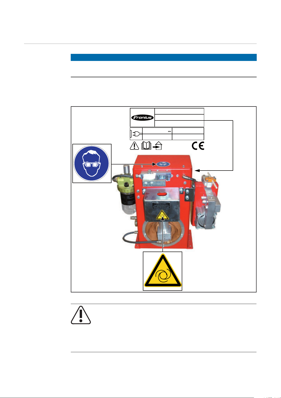
Warning notices
on the cleaning
device
NOTE!
The cleaning device is fitted with warning notices and a rating plate.
The warning notices and rating plate must not be removed or painted over.
The locations of the warning notices are shown on the Robacta Reamer Twin as
an example. On the Robacta Reamer Alu Edition and Robacta Reamer Alu
3000upm the warning notices are in the same location.
Warning notices on the cleaning device
WARNING! Risk of serious injury from:
mechanically powered parts
-
compressed air/parting agent mixture escaping from the part-
-
ing agent spray nozzles
flying parts (shavings, etc.)
-
Keep device free from current and pressure during maintenance
and servicing.
20

Do not use the functions described here until you have thoroughly
read and understood the following documents:
these operating instructions
-
all the operating instructions for the system components, es-
-
pecially the safety rules
For indoor use only
Wear eye protection
Notice warning of automatic start-up of the device
EN
21

Transport
Transport
devices
Transport notices on the
packaging
The device is to be transported by the following devices:
On pallets using a forklift truck
-
On pallets using a lift truck
-
Manual
-
WARNING!
Danger from machines and objects falling.
This can result in serious injury and damage to property.
Secure the device to prevent it from falling over when transporting on a fork-
▶
lift truck or lift truck.
Avoid sudden changes in direction, braking or acceleration.
▶
CAUTION!
Danger due to improper transport.
This can result in damage to property.
Observe the transport notices on the device packaging.
▶
22

Controls, connections and mechan-
ical components
23

24

Safety
Safety Observe the following safety instructions for all work described in the "Control
elements, connections and mechanical components" section.
WARNING!
Operating the equipment incorrectly can cause serious injury and damage.
The functions described must only be used by trained and qualified personnel.
Do not use the functions described here until you have thoroughly read and understood the following documents:
these operating instructions
▶
all the operating instructions for the system components, especially the
▶
safety rules
EN
25

Control elements, connections and mechanical
(1)
(2)
(3)
(4)
(5)
(6)
(7)
components of the Robacta Reamer Alu Edition
and Robacta Reamer Alu 3000upm
Control elements, connections and mechanical components
Side view
(1) Compressed air connection
for a dry compressed air supply at 6 bar (86.99 psi)
Thread identification compressed air connection: G ¼“
(2) Harting Han6P connection socket (X1)
for a + 24 V DC supply
CAUTION!
Risk of damage to Harting Han6P connection (X1) supply due to overcurrent.
Secure supply against overcurrent with a 500 mA slow-blow fuse.
(3) "Cleaning" screw
for manually checking the following functions:
Cleaning motor ON/OFF
-
Lifting device UP/DOWN
-
Gas nozzle clamping device extending/retracting
-
(4) Gas nozzle clamping device
holds the gas nozzle in place during cleaning
(5) Protective covering
Front view
26
(6) Cleaning motor
drives the cleaning brush / cleaning cutter
(7) Lifting device
lifts the cleaning motor and the cleaning brush / cleaning cutter to the
cleaning position ready to commence cleaning

Robacta Reamer Twin control elements, connec-
(5)
(8)
(7)
(6)
(1)
(2)
(4)
(3)
tions and mechanical components
Control elements, connections and mechanical components
(1) Parting agent adjuster
for setting the spray amount on the parting agent spray nozzles
EN
(2) Compressed air connection
for a dry compressed air supply at 6 bar (86.99 psi)
Thread identification compressed air connection: G ¼“
(3) Harting Han6P connection socket (X1)
for a + 24 V DC supply
CAUTION!
Risk of damage to Harting Han6P connection (X1) supply due to overcurrent.
Secure supply against overcurrent with a 500 mA slow-blow fuse.
(4) "Cleaning" button
for manually checking the following functions:
Cleaning motor ON/OFF
-
Compressed air and parting agent supply to parting agent spray
-
nozzles (compressed air/parting agent mixture is sprayed out of the
parting agent spray nozzles)
Lifting device UP/DOWN
-
Gas nozzle clamping device extending/retracting
-
(5) Gas nozzle clamping device
holds the gas nozzle in place during cleaning
(6) Protective covering
(7) Cleaning motor
drives the cleaning cutter
(8) Lifting device
lifts the cleaning motor and the cleaning cutter to the cleaning position
ready to commence cleaning
27

((1111))
(10)(10)
(9)(9)
((1111))
(9) Wire cutter valve lever
activates the wire cutter
(10) Wire cutter
(11) Parting agent spray nozzles
sprays the parting agent into the interior and onto the front of the gas
nozzles using compressed air
28

Harting Han6P connecting plug pin assignment
3
2
5 4
1
6
(X1) for robot control
General
Danger from overcurrent.
Damage to the Harting Han6P connection supply may result.
▶
To avoid malfunction, keep the cable length between the cleaning device and robot control as short as possible.
The Harting Han6P connecting plug (X1) for connecting the cleaning device to
the robot control is included in the scope of supply. The cable harness must be
adapted to the connection technology on the robot control.
Harting Han6P
connecting plug
pin assignment
(X1)
CAUTION!
Secure the power supply of the cleaning device against overcurrent with a
500 mA slow-blow fuse.
NOTE!
Input and output signals on the
Robacta Reamer Alu brush head:
Start cleaning input signal (clean-
1.
ing motor ON, lifting device UP,
compressed air supply to cleaning
nozzles ON)
Not assigned
2.
GND
3.
+ 24 V DC
4.
Gas nozzle free output signal
5.
Earthing
6.
EN
(see circuit diagrams in appendix)
Harting Han6P connecting plug pin assignment
(X1) - cable-end view
29

30

Installation and commissioning
31

32

Safety
Safety Observe the following safety rules for all work described in the "Installation and
start-up" section.
WARNING!
Incorrect operation or shoddy workmanship can cause serious injury or damage.
All activities described in these operating instructions may only be carried out by
trained and qualified personnel. All functions described in these operating instructions may only be used by trained and qualified personnel. Do not carry out
any of the work or use any of the functions described until you have fully read
and understood the following documents:
these operating instructions
▶
all the operating instructions for the system components, especially the
▶
safety rules
WARNING!
Machines that start up automatically can cause serious injury and damage.
In addition to these operating instructions, the safety rules issued by the manufacturers of the robot and welding systems must also be observed. For your personal safety, ensure that all protective measures have been taken and will remain
in place while you are in the working area of the robot.
EN
WARNING!
Risk of serious injury from:
mechanically powered parts
▶
flying parts (shavings, etc.)
▶
compressed air/parting agent mixture escaping from the parting-agent injec-
▶
tion nozzles
Before performing work on the cleaning device or any connected system
▶
components:
disconnect the customer compressed air and power supplies from the clean-
▶
ing device and the connected system components, and ensure that they remain disconnected until work is complete
ensure that the cleaning device is depressurised - please see the "Ensuring
▶
that the cleaning device is depressurised" section below for the relevant instructions
33

WARNING!
Whenever the cleaning device and connected system components are supplied
with voltage and/or compressed air, a risk of serious injury exists from:
rotating cleaning cutter / rotating cleaning brush
▶
lifting device moving up/down
▶
extending/retracting gas nozzle clamping device
▶
activated wire cutter
▶
flying parts (shavings, etc.)
▶
compressed air/parting agent mixture escaping from the parting-agent injec-
▶
tion nozzles
If work has to be performed on the cleaning device while it is being supplied with
voltage and/or compressed air:
keep your body, especially your hands, face, hair, any objects and all clothing
▶
away from the cleaning cutter / cleaning brush, lifting device, gas nozzle
clamping device, wire cutter and parting-agent injection nozzles
wear ear protection
▶
wear protective goggles with side protection
▶
Ensuring that
the cleaning
device is depressurised
Attempt to briefly activate the cleaning device without any compressed air supply to check whether the cleaning device is depressurised. Proceed as follows:
Take protective measures:
1
The cleaning cutter / cleaning brush, lifting device, gas nozzle clamping
-
device, wire cutter and parting-agent injection nozzles could start up.
Therefore keep your body, especially your hands, face and hair, any objects and all clothing away from the parts referred to above
wear ear protection
-
wear protective goggles with side protection
-
Ensure that the cleaning device has been disconnected from the compressed
2
air supply
On the Robacta Reamer Alu Edition, Robacta Reamer Alu 3000upm:
Briefly turn the "Cleaning" screw on the cleaning device 90° to the right, then
3
turn it straight back to its original position
If the cleaning device does not respond to the turning of the screw, the
-
cleaning device is depressurised
If the cleaning device responds to the turning of the screw, the cleaning
-
device is still connected to a compressed air supply.
If this is the case, you must disconnect the cleaning device from the compressed air supply and check again that the cleaning device is depressurised
before starting work
34
On the Robacta Reamer Twin:
Briefly press the valve lever on the cleaning device wire cutter to the side by
3
more than 15° using a tool

If the cleaning device wire cutter does not respond to the movement of the
-
valve lever, the cleaning device (including the wire cutter) is depressurised
If the wire cutter responds to the movement of the valve lever, the cleaning
-
device (and therefore also the wire cutter) is still connected to a compressed
air supply.
If this is the case, you must disconnect the cleaning device from the compressed air supply and check again that the cleaning device is depressurised
before starting work
EN
35

Before commissioning
Proper use The cleaning device is to be used exclusively for cleaning Fronius robot welding
torches, especially the gas nozzle and its interior, in automatic mode and within
the scope of the technical data. Any use above and beyond this purpose is
deemed improper. The manufacturer shall not be held liable for any damage
arising from such usage.
Proper use includes:
carefully reading these operating instructions
-
following all the instructions and safety rules in these operating instructions
-
performing all stipulated inspection and maintenance work
-
Operators, maintenance personnel
Setup regulations
WARNING!
Risk of machines starting automatically.
This can result in serious injury and damage to property.
The device must only be used by 1 person at a time. It is also necessary to
▶
ensure that no one else is within the working area of the device when the
device is being used.
The device must only be serviced by 1 person at a time. It is also necessary to
▶
ensure that no one else is within the working area of the device when the
device is being serviced.
The cleaning device is tested to protection class IP 21, meaning:
Protection against penetration by solid foreign bodies with diameters > 12.5
-
mm (0.49 in.)
No protection against the ingress of water
-
The device must not be set up and operated outdoors. The built in electrical
parts must be protected from direct wetting.
WARNING!
Compressed air
supply specifications
36
Danger from machines falling or toppling over.
This can result in serious injury and damage to property.
Always secure the cleaning device to the underlying surface.
▶
To ensure that the cleaning device functions correctly, the following compressed
air supply specifications must be met:
Establish compressed air supply using a pressure limiter and compressed air
-
filter
Provide compressed air quality conforming to ISO 8573-1:2001, class 7 4 3,
-
instrument air
-
Solid particle concentration £ 10 mg/m
Vapour pressure dew point £ + 3°C
-
-
Oil concentration £ 1 mg/m
3
3

Measures for the
safe operation of
the device with
untrained personnel
If untrained operators have access to the device, its compressed air supply must
be disconnected for the duration of work in accordance with 'Performance Level
d' of the ISO 13849-1 standard.
To ensure that the compressed air supply is interrupted as required, MS6-SV
pressure build-up and pressure relief valves from FESTO are recommended.
EN
37

Screwing the cleaning device to the underlying
surface
Screwing the
cleaning device
and installation
stand to the underlying surface
WARNING!
Danger from machines falling or toppling over.
This can result in serious injury and damage to property.
Always secure the installation stand to the underlying surface.
▶
The screws for fastening the installation stand are not included in the scope
▶
of supply of the installation stand. The installer is responsible for selecting
the right type of screws or bolts.
Always secure the cleaning device to the installation stand.
▶
Place the optionally available in-
1
stallation stand on a level, firm and
vibration-free surface (foundation)
Position the installation stand
-
in such a way that the distance
the robot has to travel to the
cleaning device on the installation stand is as short as possible
Tightly screw the installation stand
2
to the surface (foundation) using
the selected mounting materials
Screw on the cleaning device and the spatter tray retainer using the fixings supplied with the cleaning device.
3
Place components on the installation stand and secure
38

4
Attach the spatter tray retainer as shown
EN
Screwing the
cleaning device
to the underlying
surface
WARNING!
Danger from machines falling or toppling over.
This can result in serious injury and damage to property.
Always secure the cleaning device to the underlying surface.
▶
If the underlying surface thickness is less than 5 mm (0.197 in.), use the fix-
▶
ings supplied with the cleaning device for fastening.
If the underlying surface thickness is greater than 5 mm (0.197 in.), do not
▶
use the fixings supplied for fastening. In this situation the installer is responsible for selecting the right type of fixing.
Place the cleaning device and the spatter tray retainer on a level, firm and vi-
1
bration-free surface (foundation).
Position the cleaning device in such a way that the distance the robot has
-
to travel to the cleaning position is as short as possible.
2
Place components on the underlying surface and secure
39

3
Attach the spatter tray retainer as shown
40

Torch cleaning position
228800 mmmm ((1111..0022 iinn..))
2288 00 mm mm ((11 11 ..0022 iinn..))
1100 mmmm ((00..3399 iinn..))
Welding torch
cleaning position
- Robacta Reamer Alu Edition
Welding torch
cleaning position
- Robacta Reamer Alu 3000upm
EN
Welding torch
cleaning position
- Robacta Reamer Twin
NOTE!
Ensure that the coolant lines on the
gas nozzle cannot be damaged by the
extending/retracting gas nozzle
clamping device.
41

Adjusting the gas nozzle clamping device on the
(1)
(3)
(2)
(4)
Robacta Reamer Alu Edition and Robacta Reamer
Alu 3000upm
Adjusting the
gas nozzle
clamping device
NOTE!
The gas nozzle clamping device must be adjusted so that no bearing pressure is
transferred to the robot.
The gas nozzle must only be clamped onto the cylindrical surface.
Loosen Allen screws on the guide
1
bolts (1) and (2)
Move the welding torch to the
2
cleaning position
centrally with respect to the
-
cleaning motor
Using the adjusting screw (3), posi-
3
tion the clamping device (4) so that
the clamping device is on the gas
nozzle
Tighten Allen screws on the guide bolts (1) and (2)
4
NOTE!
The gas nozzle must be clamped centrally over the cleaning motor.
42

Fitting the cleaning brush on the Robacta Reamer
Alu Edition
Fitting the
cleaning brush
A cleaning brush that has become very hot through use can cause severe burns.
Before handling the cleaning brush, allow cleaning brush to cool to room temperature (+25°C, +77 °F).
Only use the device manufacturer's contact tips, gas nozzles and cleaning
brushes.
If other manufacturers' products are used, trouble-free operation of the device
cannot be guaranteed. The manufacturer accepts no liability for damage resulting from the use of other manufacturers' contact tips, gas nozzles or cleaning
brushes.
The cleaning brush and adapter are not included in the scope of supply.
Consult the device manufacturer's spare parts list for the appropriate cleaning
brush.
EN
CAUTION!
NOTE!
NOTE!
Remove the protective covering from the cleaning device
1
2
Fit the protective covering to the cleaning device in its original position
3
43

Fitting the cleaning cutter on the Robacta Reamer Alu 3000upm
Fitting the
cleaning cutter
CAUTION!
A cleaning cutter that has become very hot through use can cause severe burns.
Before handling cleaning cutters, allow cleaning cutter to cool to room temperature (+25°C, +77 °F).
NOTE!
Only use the device manufacturer's contact tips, gas nozzles and cleaning cutters.
If other manufacturers' products are used, trouble-free operation of the device
cannot be guaranteed. The manufacturer accepts no liability for damage resulting from the use of other manufacturers' contact tips, gas nozzles or cleaning
cutters.
NOTE!
The cleaning cutter and adapter are not included in the scope of supply.
Consult the device manufacturer's spare parts list for the appropriate cleaning
cutter and adapter.
Remove the protective covering from the cleaning device
1
2
44
Fit the protective covering to the cleaning device in its original position
3

Fitting the cleaning cutter on the Robacta Reamer Twin
Fitting the
cleaning cutter
CAUTION!
Danger due to cleaning cutter that has become very hot through use.
This can result in severe burns.
Before handling cleaning cutters, allow cleaning cutter to cool to room tem-
▶
perature (+25 °C, +77 °F).
CAUTION!
Danger from incompatible wearing parts.
This can result in damage to property and malfunctions.
Only use the device manufacturer's contact tips, gas nozzles and cleaning
▶
cutters. No liability is accepted for damage caused by the use of contact tips,
gas nozzles or cleaning cutters from third-party manufacturers.
The cleaning cutter is not part of the scope of suppl.. Consult the manufacturer's
spare parts list for the appropriate cleaning cutter: https://spareparts.froni-
us.com/
EN
Remove the protective covering from the cleaning device
1
2
Fit the protective covering to the cleaning device in its original position
3
45

Adjusting the Robacta Reamer Alu Edition lifting
(1)(1)
(2)(2)
(4)(4)(4)(4)
(2)(2)(2)(2)
(5)(5)(5)(5)
(3)(3)(3)(3)
(6)(6)(6)(6)
1/31/31/31/3
2/32/32/32/3
device
Adjusting the
lifting device
Remove protective covering (1)
1
Ensure that the lifting device is in
2
its lowest position
Loosen screw (2) on the lifting
3
device
Move the welding torch to the
4
cleaning position
46
Push the lifting device (3) by hand into its highest position and hold in place
5
Manually push cleaning motor (4) and cleaning brush to the cleaning posi-
6
tion
see diagram (5) - correct adjustment
-
see diagram (6) - incorrect adjustment
-
Fix cleaning motor (4) in this position in the lifting device (3) - tighten screw
7
(2) on the lifting device
Carry out function test - push lifting device by hand to its highest position
8
Check that lifting device is adjusted correctly - see diagram (5). If the
-
correct adjustment is not given, readjust the lifting device
Fit the protective covering to the cleaning device in its original position
9

Adjusting the Robacta Reamer Alu 3000upm lift-
(4)(4)
(2)(2)
(5)(5) (6)(6)
(3)(3)
ing device
Adjusting the
lifting device
Remove protective covering (1)
1
Remove gas nozzle from torch
2
neck
Ensure that the lifting device is in
3
its lowest position
Loosen screw (2) on the lifting
4
device
Move the welding torch to the
5
cleaning position
Push the lifting device (3) by hand
6
into its highest position and hold in
place
Manually push cleaning motor (4)
7
and cleaning cutter to the cleaning
position
see diagram (5) for welding
-
torch and spatter guard
see diagram (6) for welding
-
torch and insulating sleeve
EN
NOTE!
The cleaning cutter must not touch any welding torch components.
Fix cleaning motor (4) in this position in the lifting device (3) - tighten screw
8
(2) on the lifting device
Carry out function test on unfitted gas nozzle - push lifting device by hand to
9
its highest position
The cleaning cutter must close around the contact tip without touching
-
it. If the cleaning cutter touches welding torch components, readjust the
lifting device
Fit gas nozzle to torch neck
10
Carry out function test on fitted gas nozzle - push lifting device by hand to
11
its highest position
The cleaning cutter must be inserted into the gas nozzle gently, without
-
touching it. If the cleaning cutter touches welding torch components, readjust the lifting device
Fit the protective covering to the cleaning device in its original position
12
47

Adjusting the Robacta Reamer Twin lifting device
(1)(1)
(2)(2)
(3)(3)
(5)(5)(5)
(4)(4)(4)
000
,,,
555
---
111
mmm
mmm
...
000
222
---
...
000
444
iii
nnn
...
Adjusting the
lifting device
It is recommended that one of the following adjustment aids is used to adjust the
lifting device:
Robacta Twin 900 adjustment aid, item no. 42,0001,5560
-
An adjustment aid is not necessary when the gas nozzle is open, as the welding
torch is clamped above the gas nozzle. The gas nozzle can be removed beforehand. The bracket must be back in the starting position. When the gas nozzle is
mounted, the bracket must be closed.
Remove the protective cover (1)
1
Ensure that the lifting device is in
2
its lowest lift position
Loosen the screw (2) on the lifting
3
device
Move the welding torch to the
4
cleaning position (including fitted
adjustment aid)
Push the lifting device (3) by hand
5
into its highest lift position and
hold in place
Push the cleaning motor (4) and
6
cleaning cutter by hand into the
cleaning position (5)
NOTE!
The cleaning cutter must not touch
any welding torch components.
Fix the cleaning motor (4) in this
7
position in the lifting device - tighten the screw (2) on the lifting
device
Fit the protective cover to the
8
cleaning device in its original position
48

Starting up the Robacta Reamer Twin parting
321
(1)
(1)
(4) (3)
(2)
agent nebuliser
Starting up the
parting agent
nebuliser
NOTE!
Only use "Robacta Reamer" parting agent (item number 42,0411,8042).
The composition of this parting agent is designed specifically for the cleaning
device. If other manufacturers' products are used, trouble-free operation cannot
be guaranteed.
NOTE!
Use the parting agent - spray unit option to achieve sufficient wetting of the entire Twin welding torch interior.
With the parting agent - spray unit option, the parting agent is sprayed through
the blow out line directly into the welding torch interior.
Open the sealing plug (1)
1
Fill with "Robacta Reamer" parting agent using the filling funnel (2)
2
Close the sealing plug (1)
3
EN
NOTE!
If the spray amount is not sufficient after starting up the cleaning device, increase it as required:
by adjusting the spray time using the robot control - a spray time of ~ 0.7
▶
seconds is recommended
or by using the parting agent adjuster (4): remove the safety clamp (3), use a
▶
screwdriver to set the parting agent adjuster (4) so that the welding torch interior is coated with a thin layer of parting agent (0.2-0.5 ml) after the spraying action is complete
49

Correct adjustment of the parting agent spray
nozzles on the
Robacta Reamer
Twin
NOTE!
Both spray jets of parting agent must
meet in front of the gas nozzle, so that
they fully enter the nozzle.
50

Installing mechanically-controlled wire cutter on
(1)(2)
1
2
1
2
(3)
(4)
(3)
(3)
the Robacta Reamer Alu Edition and Robacta
Reamer Alu 3000upm (optional)
Installing the
mechanicallycontrolled wire
cutter
NOTE!
Installation of the wire cutter is shown for the Robacta Reamer Alu Edition.
The wire cutter is installed in exactly the same way on the Robacta Reamer Alu
3000upm.
Position the mounting bracket (1)
1
on the wire cutter (2) as shown and
screw into place as described - using the fixings supplied
EN
Undo 3 screws and washers (3)
2
Remove cleaning device housing
3
cover (4)
51

(5)
Remove screw (5)
(6) (6)
(6)
(6)
4
Undo screws and washers (6)
5
Keep the screws and washers
-
for future use
Screw the wire cutter to the clean-
6
ing device using the previously removed screws and washers (6)
52

(7)
Cut through the compressed air
(9)
(8)
7
hose (7) in the interior of the cleaning device housing in the position
shown
Detach compressed air connection
8
(8) from compressed air connection (9)
9
EN
53

(11)
(12) (13)
(10)
(9)
(8)
Attach the wire cutter compressed
10
air connection (9) to compressed
air connection (8) on the cleaning
device housing, as shown
Insert the compressed air hose
11
(10) firmly into the compressed air
distributor (11)
Insert the two loose ends (12) and
12
(13) of the previously cut compressed air hose firmly into the
compressed air distributor (11) as
shown
Fit the cleaning device housing
13
cover (4) to the cleaning device in
its original position
54

Installing the electrically-controlled wire cutter
(1)(2)
1
2
1
2
(3)
(4)
(3)
(3)
on the Robacta Reamer Alu Edition and Robacta
Reamer Alu 3000upm (optional)
Installing the
electrically-controlled wire cutter
NOTE!
Installation of the wire cutter is shown for the Robacta Reamer Alu Edition.
The wire cutter is installed in exactly the same way on the Robacta Reamer Alu
3000upm.
Position the mounting bracket (1)
1
on the wire cutter (2) as shown and
screw into place as described - using the fixings supplied
EN
Undo 3 screws and washers (3)
2
Remove cleaning device housing
3
cover (4)
55

(5) (5)
Undo screws and washers (5)
(5)
(5)
4
Keep the screws and washers
-
for future use
Screw the wire cutter to the clean-
5
ing device using the previously removed screws and washers (5) as
shown
Fit the cleaning device housing
6
cover (4) to the cleaning device in
its original position
NOTE!
The wire cutter must be supplied with compressed air from a separate supply
line.
NOTE!
The wire cutter electrical connection must be connected to the robot control.
56

Wire cutter function
(1)
EN
Maximum wire
diameter
How the mechanically controlled wire cutter works
Wire electrodes with a diameter of up to 1.6 mm (0.063 in.) can be cut with an
electrically or mechanically-controlled wire cutter.
Two wire electrodes with a diameter of up to 1.6 mm (0.063 in.) can be cut in the
case of twin applications.
NOTE!
If you change over to a new welding torch, the mechanically controlled wire cutter must be reset!
If a torch body pushes the valve lever
(1) to the side by more than 15° with
the gas nozzle, the wire cutter is activated and the wire electrode is cut.
NOTE!
The wire electrode is cut while the
torch body is moving.
How the electrically-controlled wire cutter works
The electrically-controlled wire cutter opens and closes when there is an active
signal from the robot control.
57

Installing the compressed air supply
Establishing the
compressed air
supply for the
cleaning device,
function of the
compressed air
relief valve
To establish the compressed air supply:
Depressurise the compressed air supply line of the cleaning device and en-
1
sure that it remains depressurised for the duration of the following work on
the device
Screw the supplied compressed air relief valve into the compressed air con-
2
nection on the cleaning device
Connect the compressed air supply line to the compressed air relief valve
3
The compressed air supply to the cleaning device can be broken and re-established by moving the compressed air relief valve forwards and backwards - see
description below.
The diagram below shows the compressed air relief valve in the closed position =
no compressed air supply to the device:
Compressed air relief valve closed
The diagram below shows the compressed air relief valve in the open position =
compressed air is being supplied to the device:
Compressed air relief valve open
58

Starting up the cleaning device
EN
Prerequisites for
start-up
Start-up The cleaning device starts up when there is an active signal from the robot con-
The following requirements must be met before the cleaning device is started up:
If present, the cleaning device installation stand is bolted to underlying sur-
-
face
Cleaning device is bolted to underlying surface
-
Only on the Robacta Reamer Alu Edition and Robacta Reamer Alu 3000upm:
-
gas nozzle clamping device is adjusted
Cleaning cutter / cleaning brush has been fitted
-
Lifting device has been adjusted
-
On the Robacta Reamer Twin: Parting agent nebuliser has been started up
-
Compressed air supply has been established
-
Cleaning device is connected to robot control
-
All covers are fitted and all safety devices are intact and in their proper place
-
trol.
59

Programme sequence and signal waveform on the
Pos. C
Pos. D
Robacta Reamer Alu Edition and Robacta Reamer
Alu 3000upm
Cleaning programme sequence
- approx. 25 mm (0.98 in.) next to wire cutter
Start from position C
- Speed: high speed mode
Risk of damage.
Do not start in automated mode until the cleaning device has been properly installed and started up.
Not coating the interior of the welding torch may result in permanent soiling of
the torch when welding begins.
Always wet the interior of the welding torch with the manufacturer's parting
agent before starting automatic operation.
CAUTION!
NOTE!
Start
Wire cutter option
- approx. 25 mm (0.98 in.) Enter wire cutter
Start from position D
- Speed: 10 cm/s (236.22 ipm)
Wait 0.5 sec.
60

Pos. A
Pos. B
Start from position A
- approx. 50 mm (1.97 in.) above centre of
cleaning motor
- Speed: high speed mode
EN
Query output (Gas nozzle free output sig-
nal)
Query = Low
(Gas nozzle clamped)
- Low or High
Query = High
Stop
(Gas nozzle free)
Start from position B (cleaning position)
- Enter gas nozzle clamping device
- Speed: 10 cm/s (236.22 ipm)
Set
- Blow compressed air through welding
torch
Set
- Input "Begin cleaning"
Wait 3 sec.
Reset
- Input "Begin cleaning"
Reset
- Blow compressed air through welding
torch
Wait 1.5 sec.
61

Pos. A
LO
HI
LO
HI
(1)
(2)
(3)
(4)
Query output (Gas nozzle free output sig-
nal)
- Low or High
Query = Low
(Gas nozzle clamped)
Query = High
(Gas nozzle free)
Start from position A
- approx. 50 mm (1.97 in.) above centre of
cleaning device
- Speed: 10 cm/s (236.22 ipm)
End
Signal waveform
Stop
62
No. Meaning
(1) Input "Begin cleaning"
(2) Output "Gas nozzle free"
(3) Gas nozzle free
(4) Cleaning time: 3.0 - 5.0 seconds

Robacta Reamer Twin programme sequence and
Pos. A
Pos. B
signal waveform
Cleaning programme sequence
- approx. 25 mm (0.98 in.) next to wire cutter
Start from position A
- Speed: high speed mode
Risk of damage.
Do not start in automated mode until the cleaning device has been properly installed and started up.
Not coating the interior of the welding torch may result in permanent soiling of
the torch when welding begins.
Always wet the interior of the welding torch with the manufacturer's parting
agent before starting automatic operation.
CAUTION!
NOTE!
Start
EN
- approx. 25 mm (0.98 in.) Enter wire cutter
- The wire cutter is actuated by the valve
Start from position B
- Speed: 10 cm/s (236.22 ipm)
lever of the wire cutter
Wait 0.5 sec.
63

Pos. C
Pos. D
Start from position C
- approx. 50 mm (1.97 in.) above centre of
cleaning device
- Speed: high speed mode
Query output (Gas nozzle free output sig-
nal)
Query = Low
(Gas nozzle clamped)
- Low or High
Query = High
(Gas nozzle free)
Reset
- Input "Begin cleaning"
Query output (Gas nozzle free output sig-
nal)
- Low or High
Query = High
(Gas nozzle free)
Query = Low
(Gas nozzle
clamped)
Stop
Start from position D (cleaning position)
- Enter gas nozzle clamping device
- Speed: 10 cm/s (236.22 ipm)
Reset
- Blow compressed air through welding
torch
Set
- Input "Begin cleaning"
64

Cleaning procedure
Input "Begin cleaning"
-
Gas nozzle clamping device clamps the gas nozzle
-
Cleaning cutter cleans the first side of the welding torch for approx. 3 sec.
-
Cleaning motor moves to the starting position
-
Gas nozzle clamping device opens for approx. 0.5 sec. to allow the cleaning motor to move
-
to the second side of the welding torch
Gas nozzle clamping device clamps the gas nozzle again
-
Cleaning cutter cleans the second side of the welding torch for approx. 3 sec.
-
Cleaning motor moves to the starting position
-
Gas nozzle clamping device opens for approx. 0.5 sec. to allow the cleaning motor to move
-
to the first side of the welding torch - at this time the "Begin cleaning" signal must be reset
EN
- Input "Begin cleaning"
- Blow compressed air through welding
Query output (Gas nozzle free output sig-
Wait 7 sec.
Reset
Reset
torch
Wait 1.5 sec.
nal)
- Low or High
Query = High
(Gas nozzle free)
Query = Low
(Gas nozzle clamped)
- Input "Begin cleaning"
Reset
Query output (Gas nozzle free output sig-
nal)
- Low or High
Query = High
(Gas nozzle free)
Query = Low
(Gas nozzle
clamped)
Stop
65

Pos. C
LO
HI
LO
HI
(1)
(2)
(3) (4)
(5)
Start from position C
- approx. 50 mm (1.97 in.) above centre of
cleaning device
- Speed: 10 cm/s (236.22 ipm)
Signal waveform
End
No. Meaning
(1) Input "Begin cleaning"
(2) Output "Gas nozzle released"
(3) Gas nozzle released (Cleaning, page 1)
(4) Gas nozzle released (Cleaning, page 2)
(5) Cleaning time: 7.0 - 7.5 seconds
66

Care, maintenance and disposal
67

68

Safety
Safety Observe the following safety rules for all work described in the "Care, mainten-
ance and disposal" section.
WARNING!
Incorrect operation or shoddy workmanship can cause serious injury or damage.
All activities described in these operating instructions may only be carried out by
trained and qualified personnel. All functions described in these operating instructions may only be used by trained and qualified personnel. Do not carry out
any of the work or use any of the functions described until you have fully read
and understood the following documents:
these operating instructions
▶
all the operating instructions for the system components, especially the
▶
safety rules
WARNING!
Machines that start up automatically can cause serious injury and damage.
In addition to these operating instructions, the safety rules issued by the manufacturers of the robot and welding systems must also be observed. For your personal safety, ensure that all protective measures have been taken and will remain
in place while you are in the working area of the robot.
EN
WARNING!
Risk of serious injury from:
mechanically powered parts
▶
flying parts (shavings, etc.)
▶
compressed air/parting agent mixture escaping from the parting-agent injec-
▶
tion nozzles
Before performing work on the cleaning device or any connected system
▶
components:
disconnect the customer compressed air and power supplies from the clean-
▶
ing device and the connected system components, and ensure that they remain disconnected until work is complete
ensure that the cleaning device is depressurised - please see the "Ensuring
▶
that the cleaning device is depressurised" section below for the relevant instructions
69

WARNING!
Whenever the cleaning device and connected system components are supplied
with voltage and/or compressed air, a risk of serious injury exists from:
rotating cleaning cutter / rotating cleaning brush
▶
lifting device moving up/down
▶
extending/retracting gas nozzle clamping device
▶
activated wire cutter
▶
flying parts (shavings, etc.)
▶
compressed air/parting agent mixture escaping from the parting-agent injec-
▶
tion nozzles
If work has to be performed on the cleaning device while it is being supplied with
voltage and/or compressed air:
keep your body, especially your hands, face, hair, any objects and all clothing
▶
away from the cleaning cutter / cleaning brush, lifting device, gas nozzle
clamping device, wire cutter and parting-agent injection nozzles
wear ear protection
▶
wear protective goggles with side protection
▶
CAUTION!
A cleaning cutter / cleaning brush that has become very hot through use can
cause severe burns.
Before handling the cleaning cutter / cleaning brush, allow cleaning cutter /
cleaning brush to cool to room temperature (+25°C, +77°F).
Ensuring that
the cleaning
device is depressurised
Attempt to briefly activate the cleaning device without any compressed air supply to check whether the cleaning device is depressurised. Proceed as follows:
Take protective measures:
1
The cleaning cutter / cleaning brush, lifting device, gas nozzle clamping
-
device, wire cutter and parting-agent injection nozzles could start up.
Therefore keep your body, especially your hands, face and hair, any objects and all clothing away from the parts referred to above
wear ear protection
-
wear protective goggles with side protection
-
Ensure that the cleaning device has been disconnected from the compressed
2
air supply
On the Robacta Reamer Alu Edition, Robacta Reamer Alu 3000upm:
Briefly turn the "Cleaning" screw on the cleaning device 90° to the right, then
3
turn it straight back to its original position
If the cleaning device does not respond to the turning of the screw, the
-
cleaning device is depressurised
If the cleaning device responds to the turning of the screw, the cleaning
-
device is still connected to a compressed air supply.
If this is the case, you must disconnect the cleaning device from the compressed air supply and check again that the cleaning device is depressurised
before starting work
70

On the Robacta Reamer Twin:
Briefly press the valve lever on the cleaning device wire cutter to the side by
3
more than 15° using a tool
If the cleaning device wire cutter does not respond to the movement of the
-
valve lever, the cleaning device (including the wire cutter) is depressurised
If the wire cutter responds to the movement of the valve lever, the cleaning
-
device (and therefore also the wire cutter) is still connected to a compressed
air supply.
If this is the case, you must disconnect the cleaning device from the compressed air supply and check again that the cleaning device is depressurised
before starting work
EN
71

Care, maintenance and disposal
General The cleaning device generally needs no maintenance. However, to keep the clean-
ing device in good working condition for years to come, several points on care
and maintenance must be observed.
Before each
start-up
Daily
Weekly
Only Robacta Reamer Twin: Check fill level in parting agent container and
-
top up if necessary
Check the cleaning cutter / cleaning brushes for wear and replace if neces-
-
sary
Empty the cleaning device spatter tray
-
If fitted, empty the wire cutter tray
-
Perform a general visual inspection on the device
-
CAUTION!
Danger from cleaning agents containing solvents.
This can result in damage to property.
Only use solvent-free cleaning products on the cleaning device.
▶
Remove parting agent deposits and dirt from device
1
NOTE!
Only use solvent-free cleaning products on the parting agent container.
Only Robacta Reamer Twin:
Check parting agent container for soiling and clean if necessary
-
Blow through the suction filter in the parting agent container using com-
-
pressed air from the inside outwards through the suction hose (see "Starting
up the Robacta Reamer Twin parting agent nebuliser")
Every 6 months
As necessary Open the device and
Disposal Dispose of in accordance with the applicable national and local regulations.
Open the device and check the pneumatic valves for
1
Leaks
-
The secure seating of all screws
-
The secure seating of all screw joints on the pneumatic valves
-
Clean inside of device using dry reduced compressed air
1
Lightly oil the lifting device cylinder guides
2
Restore the original condition of the device
3
72

Troubleshooting
73

74

Safety
Safety Observe the following safety rules for all work described in the "Troubleshooting"
section.
WARNING!
Incorrect operation or shoddy workmanship can cause serious injury or damage.
All activities described in these operating instructions may only be carried out by
trained and qualified personnel. All functions described in these operating instructions may only be used by trained and qualified personnel. Do not carry out
any of the work or use any of the functions described until you have fully read
and understood the following documents:
these operating instructions
▶
all the operating instructions for the system components, especially the
▶
safety rules
WARNING!
Machines that start up automatically can cause serious injury and damage.
In addition to these operating instructions, the safety rules issued by the manufacturers of the robot and welding systems must also be observed. For your personal safety, ensure that all protective measures have been taken and will remain
in place while you are in the working area of the robot.
EN
WARNING!
Risk of serious injury from:
mechanically powered parts
▶
flying parts (shavings, etc.)
▶
compressed air/parting agent mixture escaping from the parting-agent injec-
▶
tion nozzles
Before performing work on the cleaning device or any connected system
▶
components:
disconnect the customer compressed air and power supplies from the clean-
▶
ing device and the connected system components, and ensure that they remain disconnected until work is complete
ensure that the cleaning device is depressurised - please see the "Ensuring
▶
that the cleaning device is depressurised" section below for the relevant instructions
75

WARNING!
Whenever the cleaning device and connected system components are supplied
with voltage and/or compressed air, a risk of serious injury exists from:
rotating cleaning cutter / rotating cleaning brush
▶
lifting device moving up/down
▶
extending/retracting gas nozzle clamping device
▶
activated wire cutter
▶
flying parts (shavings, etc.)
▶
compressed air/parting agent mixture escaping from the parting-agent injec-
▶
tion nozzles
If work has to be performed on the cleaning device while it is being supplied with
voltage and/or compressed air:
keep your body, especially your hands, face, hair, any objects and all clothing
▶
away from the cleaning cutter / cleaning brush, lifting device, gas nozzle
clamping device, wire cutter and parting-agent injection nozzles
wear ear protection
▶
wear protective goggles with side protection
▶
CAUTION!
A cleaning cutter / cleaning brush that has become very hot through use can
cause severe burns.
Before handling the cleaning cutter / cleaning brush, allow cleaning cutter /
cleaning brush to cool to room temperature (+25°C, +77°F).
Ensuring that
the cleaning
device is depressurised
Attempt to briefly activate the cleaning device without any compressed air supply to check whether the cleaning device is depressurised. Proceed as follows:
Take protective measures:
1
The cleaning cutter / cleaning brush, lifting device, gas nozzle clamping
-
device, wire cutter and parting-agent injection nozzles could start up.
Therefore keep your body, especially your hands, face and hair, any objects and all clothing away from the parts referred to above
wear ear protection
-
wear protective goggles with side protection
-
Ensure that the cleaning device has been disconnected from the compressed
2
air supply
On the Robacta Reamer Alu Edition, Robacta Reamer Alu 3000upm:
Briefly turn the "Cleaning" screw on the cleaning device 90° to the right, then
3
turn it straight back to its original position
If the cleaning device does not respond to the turning of the screw, the
-
cleaning device is depressurised
If the cleaning device responds to the turning of the screw, the cleaning
-
device is still connected to a compressed air supply.
If this is the case, you must disconnect the cleaning device from the compressed air supply and check again that the cleaning device is depressurised
before starting work
76

On the Robacta Reamer Twin:
Briefly press the valve lever on the cleaning device wire cutter to the side by
3
more than 15° using a tool
If the cleaning device wire cutter does not respond to the movement of the
-
valve lever, the cleaning device (including the wire cutter) is depressurised
If the wire cutter responds to the movement of the valve lever, the cleaning
-
device (and therefore also the wire cutter) is still connected to a compressed
air supply.
If this is the case, you must disconnect the cleaning device from the compressed air supply and check again that the cleaning device is depressurised
before starting work
EN
77

Troubleshooting
Errors in program sequence
Parting agent does not spray (Robacta Reamer Twin only)
Parting agent container is full
Cause:
Remedy:
Cause:
Remedy:
Cause:
Remedy:
Welding torch is poorly cleaned or damaged
Cause:
Remedy:
Cause:
Remedy:
Cause:
Remedy:
Not enough spray
Adjust spray amount
Parting agent spray nozzles are blocked
Clean parting agent spray nozzles
If cleaning does not rectify problem, contact After-Sales Service replace parting agent spray nozzles
No signal from robot
Check connection to robot control
Lifting device not adjusted properly
Adjust lifting device
Gas nozzle clamped in wrong position (not on Robacta Reamer Twin)
Adjust gas nozzle clamping device (not on Robacta Reamer Twin)
Cleaning cutter / cleaning brush not suited to welding torch shape
Fit the correct cleaning cutter / fit correct cleaning brush
Cause:
Remedy:
Cleaning cutter collides with a contact tip or gas nozzle (Robacta Reamer Twin
only)
Cause:
Remedy:
Lifting device is not moving up or down
Cause:
Remedy:
Cause:
Remedy:
Cause:
Remedy:
Cleaning cutter / cleaning brush worn
Replace cleaning cutter / cleaning brush
Incorrect swivel mechanism stop angle
Contact After-Sales Service - Adjust the swivel mechanism stop
angle
Compressed air relief valve closed
Open compressed air relief valve
No signal from robot
Check connection to robot control
Faulty sealing in lifting cylinder
Contact After-Sales Service - replace lifting cylinder
78

Cleaning motor does not work
Cause:
Remedy:
Compressed air relief valve closed
Open compressed air relief valve
EN
Cause:
Remedy:
Cause:
Remedy:
No signal from robot
Check connection to robot control
Mechanical fault on cleaning motor
Contact After-Sales Service - replace cleaning motor
79

80

Technical data
81

82

Technical data
EN
Robacta Reamer
Alu Edition and
Robacta Reamer
Alu 3000upm
Supply voltage + 24 V DC
Nominal output 3.2 W
Nominal pressure 6 bar
86.99 psi
Air consumption 420 l/min
443.81 qt./min
Thread identification compressed air connection
Harting Han6P (X1) Input: + 24 V DC / max. 150
Cleaning time 3.0 - 5.0 s
Total cycle time 4.0 - 7.5 s
Degree of protection IP 21
Mark of conformity CE, CSA
Max. noise emission (LWA) 82 dB (A)
Dimensions l x w x h 170 x 165 x 280 mm
G ¼“
mA
Output: + 24 V DC / max. 30
mA
6.69 x 6.50 x 11.02 in.
Robacta Reamer
Twin
Weight
(without optional wire cutter)
Supply voltage + 24 V DC
Nominal output 6 W
Nominal pressure 6 bar
Air consumption 420 l/min
Thread identification compressed air connection
Harting Han6P (X1) Input: + 24 V DC / max. 300
Cleaning time 7.0 - 7.5 s
Total cycle time 8.5 - 10 s
9 kg
19.84 lb.
86.99 psi
443.81 qt./min
G ¼“
mA
Output: + 24 V DC / max. 30
mA
Parting agent container capacity 0.25 l
.07 gal. (US)
Degree of protection IP 21
Mark of conformity CE, CSA
83

Max. noise emission (LWA) 82 dB (A)
Dimensions l x w x h 325 x 220 x 350 mm
12.80 x 8.66 x 13.78 in.
Weight
(without parting agent and optional wire cutter)
17 kg
37.48 lb.
84

Appendix
85

86

Circuit diagram Robacta Reamer, Robacta Reamer Alu Edition, Robacta Reamer Alu Edition
3000rpm
EN
87

Circuit diagram Robacta Reamer Twin
motor right
-X1
3
4
5
6
2
1
-1V1
A2
A1
-1S1
3
2
1
- BLUE -
- BROWN -
- BLACK -
input start cleaning
nc
GND 0VDC
+24V
PE
output gas nozzle free
motor left
-X2
1
2
3456789
10
- BLUE -
- BROWN -
- BLACK -
-1S2
1
3
2
- BLUE -
- BROWN -
- BLACK -
2
3
1
-3S1
2
1
-K1
A2
A1
3
4
-S1
1
2
2
1
1
2 4
3
-2S2
-2S1
motor right clamping device
manual cleaning
motor up
motor down
- BLUE -
- BROWN -
- BLACK -
- BLUE -
- BLUE -
- BROWN -
- BLUE -
- BROWN -
- BLUE -
- BLACK -
- BLACK -
- BLUE -
- BROWN -
- BLACK -
- BLUE -
- BLUE -
- BLUE -
- BLUE -
- BLUE -
A1
-1V2
A2
A2
-2V1
A1
motor left motor up/down
88

Robacta Reamer Twin pneumatic diagram
-3X1
-2V3
6bar/87psi
-0X1
-3A2
-2V2
-2V1
-0V1
1 3
2
-4A1
-4V1
1 3
2
4 2
1
2
1
2
1
tappet valve is
operated if cleaning
motor is lowered
-3V2
1 3
2
12
-0X1.....compressed air connector
-0V1.....start/stop valve
-1V1.....solenoid valve
-1V2.....choke fla p valve -3A2.....pne umatic motor
-3V2.....signal int erupter-2V1.....solenoid va lve
-2A1.....sliding un it
-4V1.....lever valve
-3Z1.....oiler
-3A1.....cylinder 32 mm
1 3
-1V3
1
2
-1A1
2
-1V2
1
-3V1
-1V1
5
4 2
3 5
1
4 2
3 5
-3Z1
-3X2
-3A1
-2A1
MOTOR
LEFT / RIGHT
MOTOR
UP / DOWN
SPRAYING
GAS NOZZLE CLAMP MOTOR
WIRE CUTTER
-1S1
-1S2
-2S1
-2S2
-3S1
-1V3.....choke flap valve
-1A1.....cylinder 25 mm
-2V2.....choke flap valve
-2V3.....choke flap valve
-3X1.....spraying nozzle
-3V1.....trapped valve
-3X2.....spraying nozzle
-4A1.....cylinder 63 mm
EN
89

Declarations of Conformity
DE German Deutsch EN English English FR French Française
EU-KONFORMITÄTSERKLÄRUNG 2016
EU-DECLARATION OF CONFORMITY 2016
DÉCLARATION UE DE CONFORMITÉ, 2016
Wels-Thalheim, 2016-07-07
eingapmoc aLrerutcafunaMamriF eiD
FRONIUS INTERNATIONAL GMBH
Froniusstaße 1, A-4643 Pettenbach
erklärt in alleiniger Verantwortung,
dass folgendes Produkt:
Robacta Reamer Alu
3000upm
Gasdüsenreinigungsgerät
auf das sich diese Erklärung
bezieht, mit folgenden Richtlinien
bzw. Normen übereinstimmt:
Richtlinie 2014/30/EU
Elektromag. Verträglichkeit
Richtlinie 2006/42/EG
Maschinenrichtlinie
Europäische Normen inklusive
zutreffende Änderungen
EN ISO 12100:2010
EN 61000-6-2:2005+AC:2005
EN 61000-6-4:2007+A1:2011
Die oben genannte Firma hält
Dokumentationen als Nachweis der
Erfüllung der Sicherheitsziele und
die wesentlichen Schutzanforderungen zur Einsicht bereit.
Dokumentationsverantwortlicher:
(technische Dokumentation)
Ing. Josef Fe
ichtinger
Günter Fronius Straße 1
A - 4600 Wels-Thalheim
Hereby certifies on its sole
responsibility that the following
product:
Robacta Reamer Alu
3000upm
Gas nozzle cleaner
which is explicitly referred to by this
Declaration meet the following
directives and standard(s):
Directive 2014/30/EU
Electromag. compatibility
Directive 2006/42/EC
Machinery Directive
European Standards including
relevant amendments
EN ISO 12100:2010
EN 61000-6-2:2005+AC:2005
EN 61000-6-4:2007+A1:2011
Documentation evidencing
conformity with the requirements of
the Directives is kept available for
inspection at the above
Manufacturer.
person responsible for documents:
(technical documents)
Ing. Josef Feichtinger
Günter Fronius Straße 1
A - 4600 Wels-Thalheim
se déclare seule responsable du fait
que le produit suivant:
Robacta Reamer Alu
3000upm
Appareil de nettoyage de buses gaz
qui est l’objet de la présente
déclaration correspondent aux
suivantes directives et normes:
Directive 2014/30/UE
Électromag. Compatibilité
Directive 2006/42/CE
Directive aux machines
Normes européennes avec
amendements correspondants
EN ISO 12100:2010
EN 61000-6-2:2005+AC:2005
EN 61000-6-4:2007+A1:2011
En tant que preuve de la satisfaction
des demandes de sécurité la
documentation peut être consultée
chez la compagnie susmentionnée.
responsable documentation:
(technique documentation)
Ing. Josef Feichtinger
Günter Fronius Straße 1
A - 4600 Wels-Thalheim
2016 ppa. Mag.Ing.H.Hackl
Member of Board
Chief Technology Officer
90

DE German Deutsch EN English English FR French Française
EU-KONFORMITÄTSERKLÄRUNG 2016
EU-DECLARATION OF CONFORMITY 2016
DÉCLARATION UE DE CONFORMITÉ, 2016
Wels-Thalheim, 2016-07-07
eingapmoc aLrerutcafunaMamriF eiD
FRONIUS INTERNATIONAL GMBH
Froniusstaße 1, A-4643 Pettenbach
erklärt in alleiniger Verantwortung,
dass folgendes Produkt:
Robacta Reamer Twin
Gasdüsenreinigungsgerät
auf das sich diese Erklärung
bezieht, mit folgenden Richtlinien
bzw. Normen übereinstimmt:
Richtlinie 2014/30/EU
Elektromag. Verträglichkeit
Richtlinie 2006/42/EG
Maschinenrichtlinie
Europäische Normen inklusive
zutreffende Änderungen
EN ISO 12100:2010
EN 61000-6-2:2005+AC:2005
EN 61000-6-4:2007+A1:2011
Die oben genannte Firma hält
Dokumentationen als Nachweis der
Erfüllung der Sicherheitsziele und
die wesentlichen Schutzanforderungen zur Einsicht bereit.
Dokumentationsverantwortlicher:
(technische Dokumentation)
Ing. Josef Feic
htinger
Günter Fronius Straße 1
A - 4600 Wels-Thalheim
Hereby certifies on its sole
responsibility that the following
product:
Robacta Reamer Twin
Gas nozzle cleaner
which is explicitly referred to by this
Declaration meet the following
directives and standard(s):
Directive 2014/30/EU
Electromag. compatibility
Directive 2006/42/EC
Machinery Directive
European Standards including
relevant amendments
EN ISO 12100:2010
EN 61000-6-2:2005+AC:2005
EN 61000-6-4:2007+A1:2011
Documentation evidencing
conformity with the requirements of
the Directives is kept available for
inspection at the above
Manufacturer.
person responsible for documents:
(technical documents)
Ing. Josef Feichtinger
Günter Fronius Straße 1
A - 4600 Wels-Thalheim
se déclare seule responsable du fait
que le produit suivant:
Robacta Reamer Twin
Appareil de nettoyage de buses gaz
qui est l’objet de la présente
déclaration correspondent aux
suivantes directives et normes:
Directive 2014/30/UE
Électromag. Compatibilité
Directive 2006/42/CE
Directive aux machines
Normes européennes avec
amendements correspondants
EN ISO 12100:2010
EN 61000-6-2:2005+AC:2005
EN 61000-6-4:2007+A1:2011
En tant que preuve de la satisfaction
des demandes de sécurité la
documentation peut être consultée
chez la compagnie susmentionnée.
responsable documentation:
(technique documentation)
Ing. Josef Feichtinger
Günter Fronius Straße 1
A - 4600 Wels-Thalheim
2016 ppa. Mag.Ing.H.Hackl
Member of Board
Chief Technology Officer
EN
91

Fronius International GmbH
Froniusstraße 1
4643 Pettenbach
Austria
contact@fronius.com
www.fronius.com
Under www.fronius.com/contact you will find the adresses
of all Fronius Sales & Service Partners and locations.
spareparts.fronius.com
SPAREPARTS
ONLINE
 Loading...