

Page 1

Operating
Instructions
Robacta Drive
Robacta Drive Twin
DE
EN
FR
IT
ES
PT-BR
Bedienungsanleitung
Operating instructions
Instructions de service
Istruzioni per l'uso
Manual de instrucciones
Manual de instruções
42,0410,0983 016-07102022
Page 2

Page 3

Inhaltsverzeichnis
Sicherheit 4
Sicherheit 4
Allgemeines 6
Allgemeines 6
Erstausrüstung und Werkzeug 6
Installation und Inbetriebnahme 7
Haltewinkel montieren (Standard) 7
Haltewinkel montieren (Individuell) 8
Robacta-Rohrbogen demontieren und montieren 8
Robacta Twin Rohrbogen demontieren und montieren 9
Robacta Twin Compact Pro Rohrbogen demontieren und montieren 11
Schweißbrenner-Verschleißteile wechseln Robacta 11
Schweißbrenner-Verschleißteile wechseln Robacta / MTW 500-M 12
Schweißbrenner-Verschleißteile wechseln Robacta Twin 13
Robacta Twin Compact Pro - Bauteile wechseln 14
Gasdüse wechseln Robacta 160 / 300 / 500 Robacta 700 / 700 Time MTW 500-M ConDrive
Draht-Führungseinsatz montieren 15
Draht-Führungseinsatz Twin montieren 16
Verschleißteile an der Antriebseinheit montieren 18
Kunststoff-Seele montieren 19
Stahlseele montieren 20
Kunststoff-Seele montieren (Euro) 21
Stahlseele montieren (Euro) 22
Externen Draht-Förderschlauch montieren 23
Brenner anschließen 25
Richtige Verlegung des Roboter-Schlauchpaketes 26
Bedienelemente und Funktionen 27
Einstellschraube justieren 28
Verschleißteile am Rohrbogen wechseln 28
Pflege, Wartung und Entsorgung 30
Allgemeines 30
Bei jeder Inbetriebnahme 30
Bei jedem Austausch der Draht-Spule 31
Erkennen von defekten Verschleißteilen 32
Entsorgung 32
Fehlerdiagnose, Fehlerbehebung 33
Fehlerdiagnose, Fehlerbehebung 33
Technische Daten 38
Rohrbögen 38
Drive - Schlauchpakete 40
DE
15
3
Page 4
Sicherheit
Sicherheit
WARNUNG!
Gefahr durch Fehlbedienung und fehlerhaft durchgeführte Arbeiten.
Schwere Personen- und Sachschäden können die Folge sein.
Alle in diesem Dokument beschriebenen Arbeiten und Funktionen dürfen
▶
nur von technisch geschultem Fachpersonal ausgeführt werden.
Dieses Dokument vollständig lesen und verstehen.
▶
Sämtliche Sicherheitsvorschriften und Benutzerdokumentationen dieses
▶
Gerätes und aller Systemkomponenten lesen und verstehen.
WARNUNG!
Gefahr durch elektrischen Strom.
Schwere Personen- und Sachschäden können die Folge sein.
Vor Beginn der Arbeiten alle beteiligten Geräte und Komponenten ausschal-
▶
ten und von Stromnetz trennen.
Alle beteiligten Geräte und Komponenten gegen Wiedereinschalten sichern.
▶
WARNUNG!
Gefahr durch elektrischen Strom infolge von schadhaften Systemkomponenten
und Fehlbedienung.
Schwere Personen- und Sachschäden können die Folge sein.
Sämtliche Kabel, Leitungen und Schlauchpakete müssen immer fest ange-
▶
schlossen, unbeschädigt, und korrekt isoliert sein.
Nur ausreichend dimensionierte Kabel, Leitungen und Schlauchpakete ver-
▶
wenden.
WARNUNG!
Rutschgefahr durch Kühlmittel-Austritt.
Schwere Personen- und Sachschäden können die Folge sein.
Die Kühlmittel-Schläuche der wassergekühlten Schweißbrenner immer mit
▶
dem darauf montierten Kunststoff-Verschluss verschließen, wenn diese vom
Kühlgerät oder anderen Systemkomponenten getrennt werden.
WARNUNG!
Gefahr durch heiße Systemkomponenten und / oder Betriebsmittel.
Schwere Verbrennungen und Verbrühungen können die Folge sein.
Vor Beginn der Arbeiten alle heißen Systemkomponenten und / oder Be-
▶
triebsmittel auf +25 °C / +77 °F abkühlen lassen (beispielsweise Kühlmittel,
wassergekühlte Systemkomponenten, Antriebsmotor des Drahtvorschubes, ...).
Geeignete Schutzausrüstung tragen (beispielsweise hitzebeständige Schutz-
▶
handschuhe, Schutzbrille, ...), wenn ein Abkühlen nicht möglich ist.
4
Page 5
WARNUNG!
Gefahr durch Kontakt mit giftigem Schweißrauch.
Schwere Personenschäden können die Folge sein.
Schweißrauch immer absaugen.
▶
Für ausreichend Frischluft-Zufuhr sorgen. Sicherstellen, dass eine
▶
Durchlüftungsrate von mindestens 20 m³ (169070.1 US gi) pro Stunde zu jeder Zeit gegeben ist.
Im Zweifelsfall die Schadstoffbelastung am Arbeitsplatz durch einen Sicher-
▶
heitstechniker feststellen lassen.
VORSICHT!
Gefahr durch Betrieb ohne Kühlmittel.
Sachschäden können die Folge sein.
Wassergekühlte Geräte nie ohne Kühlmittel in Betrieb nehmen.
▶
Während des Schweißens sicherstellen, dass ein ordnungsgemäßer Kühlmit-
▶
tel-Durchfluss gegeben ist - bei Verwendung von Fronius-Kühlgeräten ist
dies der Fall, wenn im Kühlmittel-Behälter des Kühlgerätes ein ordnungsgemäßer Kühlmittel-Rückfluss ersichtlich ist.
Für Schäden aufgrund von Nichtbeachtung der oben angeführten Punkte
▶
haftet der Hersteller nicht, sämtliche Gewährleistungsansprüche erlöschen.
DE
5
Page 6

Allgemeines
*
**
Allgemeines Das Roboter-Schlauchpaket Robacta Drive / Robacta Drive Twin eignet sich ne-
ben Stahl, CuSi und Aluminium-Legierungen auch bestens für das Schweißen
von Rein-Aluminium.
Der integrierte Drahtantrieb unterstützt den verwendeten Drahtvorschub und
sorgt für eine besonders gleichmäßige Drahtförderung, auch bei sehr langen
Schlauchpaketen.
Es stehen mehrere Varianten von Zentralanschlüssen zur Verfügung, sowohl mit
externer, als auch mit interner Kühlmittelanbindung. Die vielfältigen RohrbogenAusführungen ermöglichen eine gute Zugänglichkeit zur Schweißstelle.
Erstausrüstung
und Werkzeug
1
Gabelschlüssel SW 8/10
-
Triebradschlüssel
-
Ablängrohr (zum Ablängen des Draht-Führungseinsatzes)
-
Innensechskantschlüssel SW 5
-
* Beidseitige Verwendung möglich
** Schlüssel für Überwurfmutter (Option)
2
WICHTIG! Je nach Drahtdurchmesser ist für den Betrieb des Antriebes „Robac-
ta Drive“ eine Erstausrüstung erforderlich (siehe Ersatzteilliste)
6
Page 7
Installation und Inbetriebnahme
Reibahle /
Reamer /
Alésoir /
Alesatore /
Escariador /
Alar gado r
Ø6G7
Bohrer /
Drill /
Foret /
Punta del
trapano /
Broca /
Broca
Ø5,8
DE
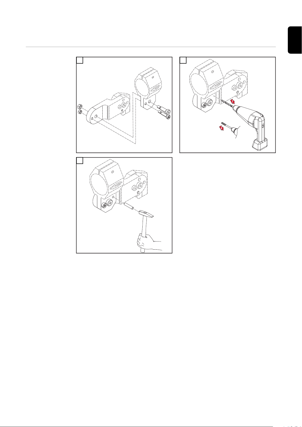
Haltewinkel
montieren (Standard)
1
3
2
WICHTIG! Zum Fixieren der eingerichteten Stellung verbohren Sie die Halter
mit Ø5,8 mm und reiben mittels einer Reibahle die Bohrung für den Pass-Stift
Ø6G7 auf.
WICHTIG! Der Haltewinkel muss mit einer Pass-Schulter-Schraube M8 und mit
einer Schraube M6 montiert werden. Nach dem Verschrauben muss noch ein
Pass-Stift (Ø6 mm) zur Sicherung eingepresst werden.
7
Page 8

Haltewinkel
Reibahle /
Reamer /
Alésoir /
Alesatore /
Escariador /
Alar gado r
Ø6G7
Bohrer /
Drill /
Foret /
Punta del
trapano /
Broca /
Broca
Ø5,8
montieren (Individuell)
1
3
2
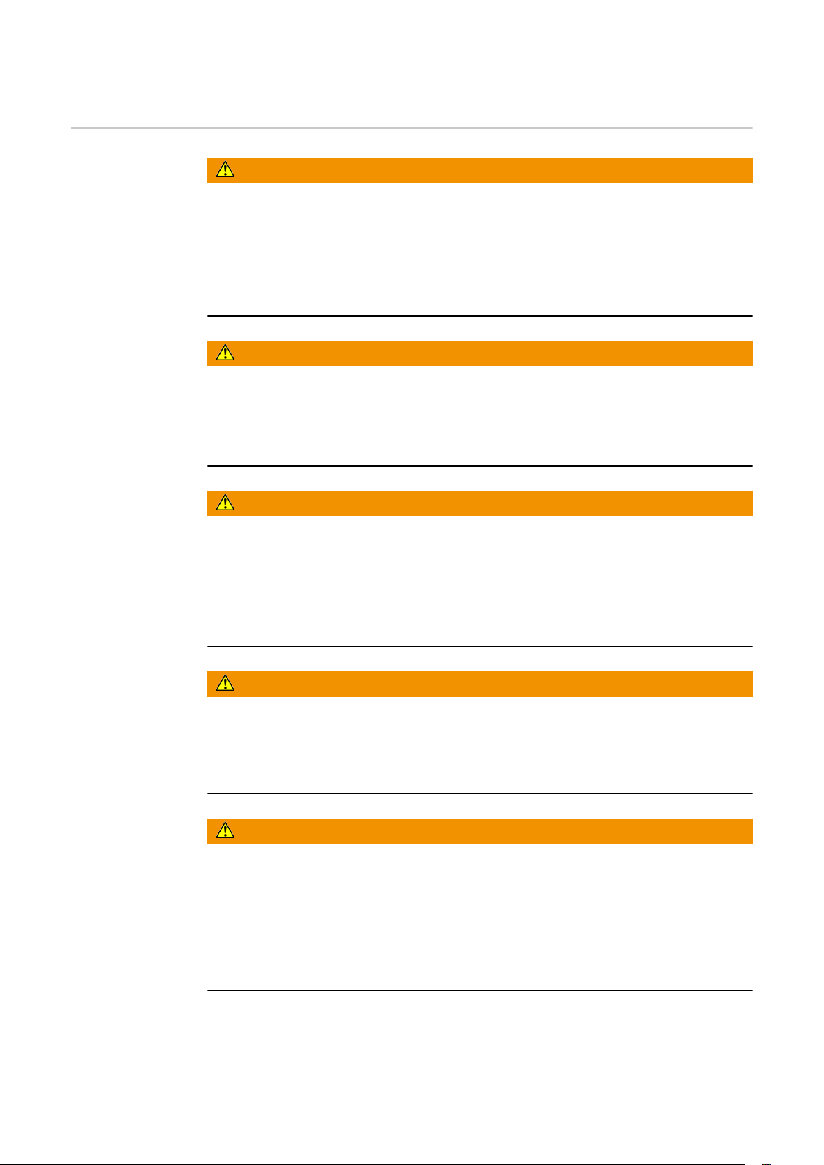
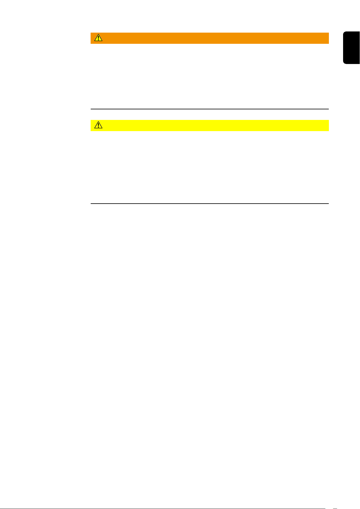
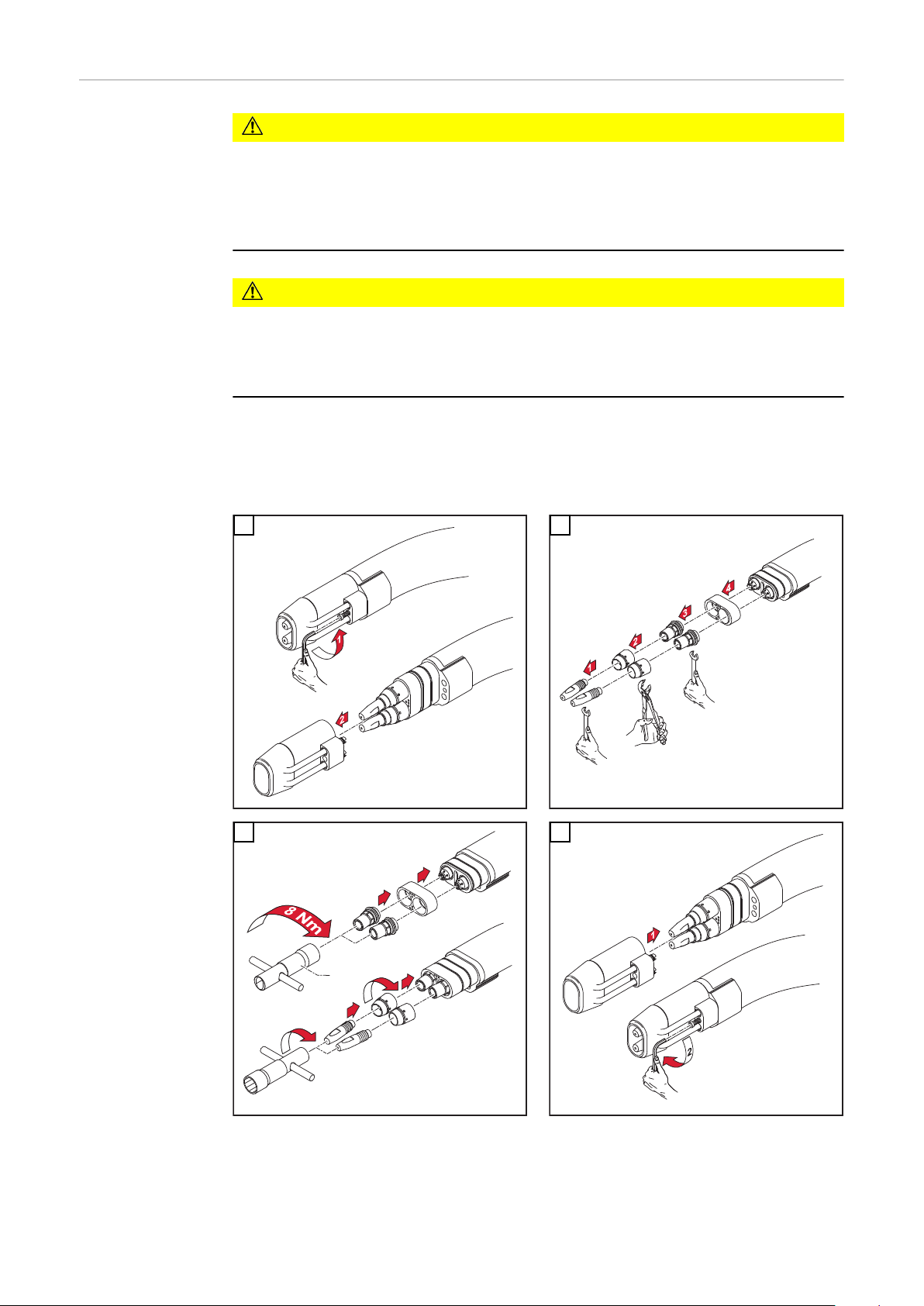
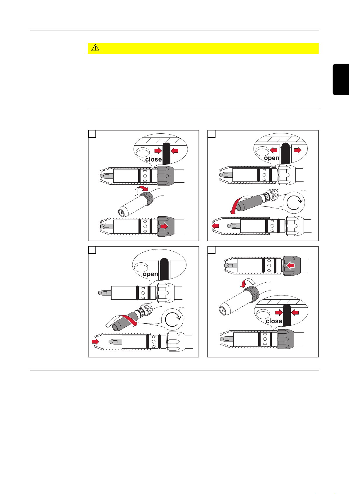
Robacta-Rohrbogen demontieren und montieren
8
WICHTIG! Zum Fixieren der eingerichteten Stellung verbohren Sie die Halter
mit Ø5,8 mm und reiben mittels einer Reibahle die Bohrung für den Pass-Stift
Ø6G7 auf.
WICHTIG! Der Haltewinkel muss mit einer Pass-Schulter-Schraube M8 montiert
werden. Danach muss der gewünschte Winkel eingestellt und zwei Pass-Stifte
(Ø6 mm) zur Sicherung eingepresst werden.
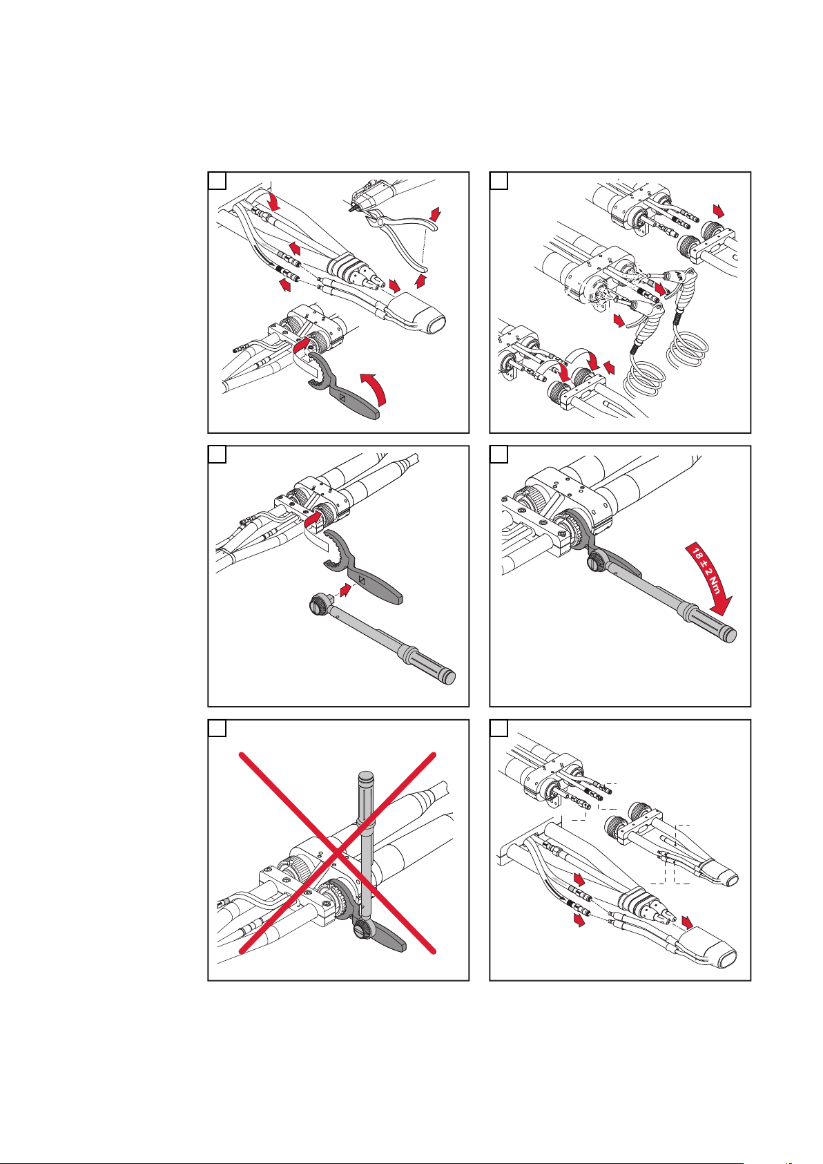
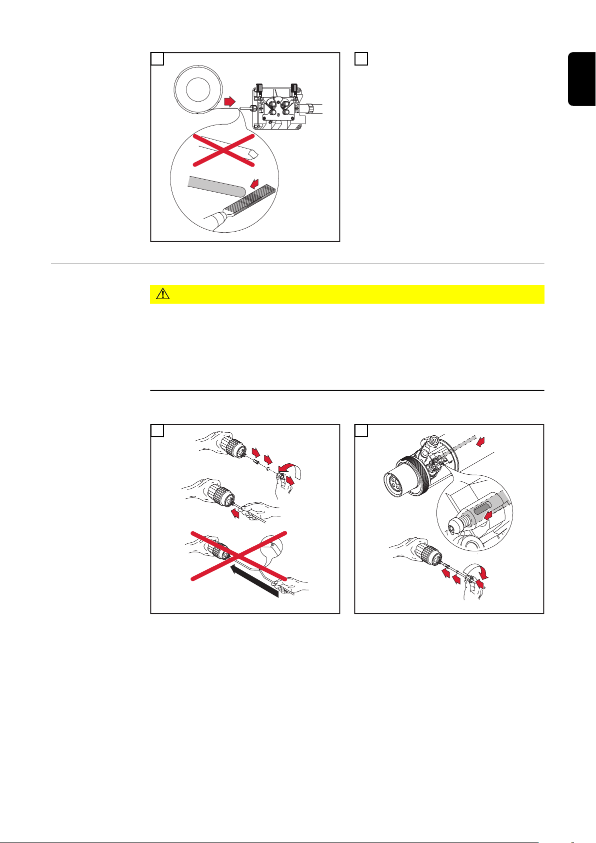
VORSICHT!
Gefahr von Kühlmittel-Austritt durch lose Überwurfmutter.
Schwerwiegende Personen- und Sachschäden können die Folge sein.
Beim Montieren des Rohrbogens auf festen Sitz der Überwurfmutter achten:
▶
Überwurfmutter mittels Gabelschlüssel anziehen.
Für ein definiertes, nachvollziehbares Anzugsmoment Gabelschlüssel und
▶
Drehmoment-Schlüssel verwenden, ideales Anzugsmoment = 18 ±2 Nm.
Page 9
1
2
1
3
4
1
4
1
3
2
1
2
3 4
2
DE
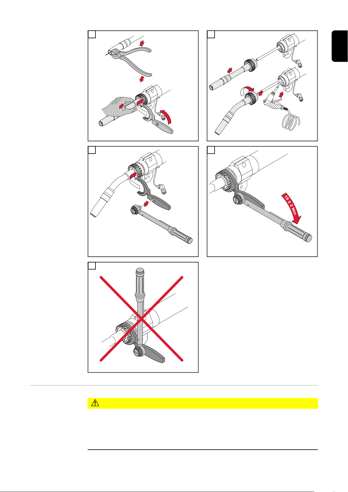
Robacta Twin
Rohrbogen demontieren und
montieren
5
VORSICHT!
Gefahr von Kühlmittel-Austritt durch lose Überwurfmuttern.
Schwerwiegende Personen- und Sachschäden können die Folge sein.
Beim Montieren des Twin-Rohrbogens auf festen Sitz der Überwurfmuttern
▶
achten: Überwurfmutter mittels Gabelschlüssel und Drehmoment-Schlüssel
anziehen, Anzugsmoment = 18 ±2 Nm.
9
Page 10
Beim An- und Abschließen der Leitungen folgende Reihenfolge einhalten:
1
1
2
3
54
5
6
7
2
3
1
6
5
4
2
1
3
x.2x.3
x.1
x.3
x.2
x.1
1
2
3
1. Ausblas-Leitung x.1
2. Wasser-Vorlauf x.2 (blau)
3. Wasser-Rücklauf x.3 (rot)
1
3 4
2
5
6
10
Page 11
Robacta Twin
Compact Pro
Rohrbogen demontieren und
montieren
DE
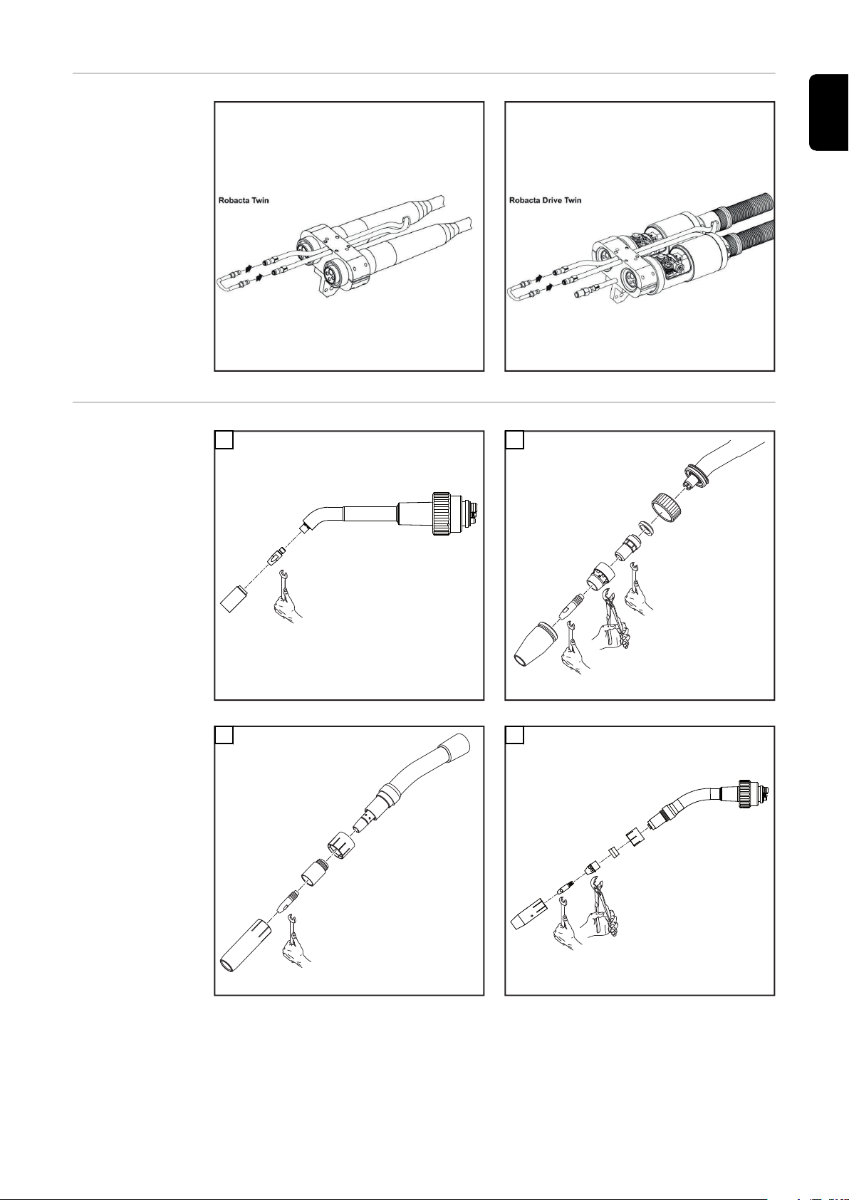
Schweißbrenner-Verschleißteile
wechseln Robacta
1
Robacta 160
3
2
Robacta 280
4
Robacta 300 / 500
Robacta 400
11
Page 12
5
6
Schweißbrenner-Verschleißteile
wechseln Robacta / MTW 500-M
Robacta 700 / 700 TIME
1
Robacta 5000
Robacta 2500
2
MTW 500-M Con-Drive
12
Page 13
Schweißbren-
1
2
1
2
3
4
1
2
*
8 Nm
3
4
1
ner-Verschleißteile
wechseln Robacta Twin
WICHTIG! Immer zwei gleiche Kontaktrohre verwenden.
VORSICHT!
Gefahr durch fehlerhaft durchgeführte Arbeiten.
Schwerwiegende Sachschäden können die Folge sein.
Unbedingt die Reihenfolge der Arbeitsschritte und die angegebenen Dreh-
▶
momente einhalten.
* Statt dem serienmäßig mitgelieferten Werkzeuges sind optional ein Dreh-
moment- Schlüssel, sowie der dazu passende Steckschlüssel erhältlich.
Damit ist sichergestellt, dass die Bauteile mit dem angegebenen Drehmoment festgezogen werden können. Artikelnummern siehe Ersatzteilliste.
DE
1
3
2
4
13
Page 14
Robacta Twin
1
2
3
4
*
Compact Pro Bauteile wechseln
VORSICHT!
Verbrennungsgefahr durch stark erhitzten Schweißbrenner oder heiße
Kühlflüssigkeit.
Schwere Verbrühungen können die Folge sein.
Das Wechseln der Bauteile, sowie das Reinigen und Überprüfen der Kompo-
▶
nenten, darf nur im abgekühlten Zustand des Schweißbrenners erfolgen.
VORSICHT!
Gefahr durch Fehlbedienung und fehlerhaft durchgeführte Arbeiten.
Schwerwiegende Sachschäden können die Folge sein.
Unbedingt die Reihenfolge der Arbeitsschritte und die angegebenen Dreh-
▶
momente einhalten.
* Statt dem serienmäßig mitgelieferten Werkzeuges sind optional ein Dreh-
moment- Schlüssel, sowie der dazu passende Steckschlüssel erhältlich.
Damit ist sichergestellt, dass die Bauteile mit dem angegebenen Drehmoment festgezogen werden können. Artikelnummern siehe Ersatzteilliste.
1 2
14
3 4
Page 15

Gasdüse wech-
1
2
1
*
*
1
1
2
seln Robacta
160 / 300 / 500
Robacta 700 /
700 Time MTW
500-M Con-Drive
VORSICHT!
Beschädigungsgefahr der O-Ringe durch unsachgemäßes Abnehmen oder Aufsetzen der Gasdüse.
Schwerwiegende Sachschäden können die Folge sein.
Gasdüse nur bei geöffneter Überwurfmutter abnehmen oder aufsetzen.
▶
Beim Aufsetzen der Gasdüse darauf achten, dass die Bohrungen des Loch-
▶
ringes genau über den Bohrungen im Brennerkörper liegen. Andernfalls ist
eine ausreichende Kühlung der Gasdüse nicht gewährleistet.
* vorgegebene Drehrichtung
DE
1
3
2
4
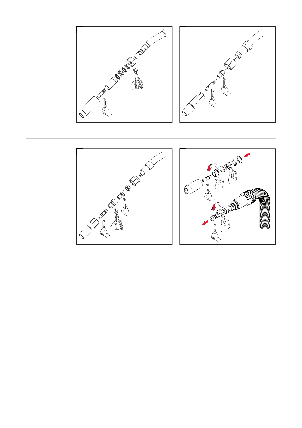
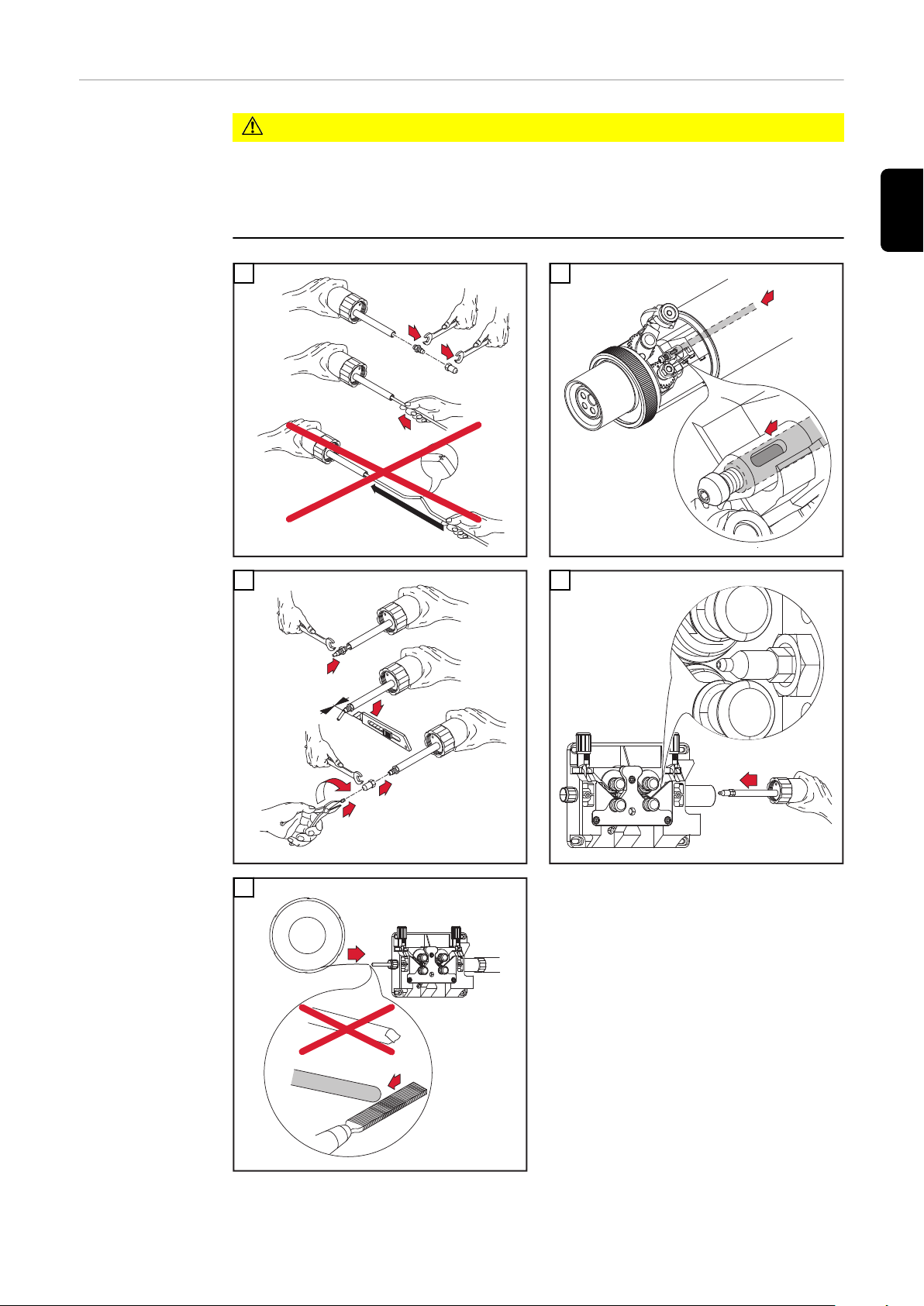
Draht-Führungseinsatz montieren
WICHTIG! Beim Ablängen des Draht-Führungseinsatzes darauf achten, dass
das Kontaktrohr im Rohrbogen fest montiert ist
-
der Draht-Führungseinsatz satt am Kontaktrohr anliegt
-
* Der Draht-Führungseinsatz 44,0350,1806 kann bei einem Robacta 280
45°-Brennerkörper nur von vorne montiert und demontiert werden.
** Kontaktrohr mit Zentrierbohrung
*** Kontaktrohr ohne Zentrierbohrung
15
Page 16
1
2
1
1
1
*
Robacta 280 45°
2
1
**
***
1
0 mm
.
0
inch
2
1
2
3
5
4
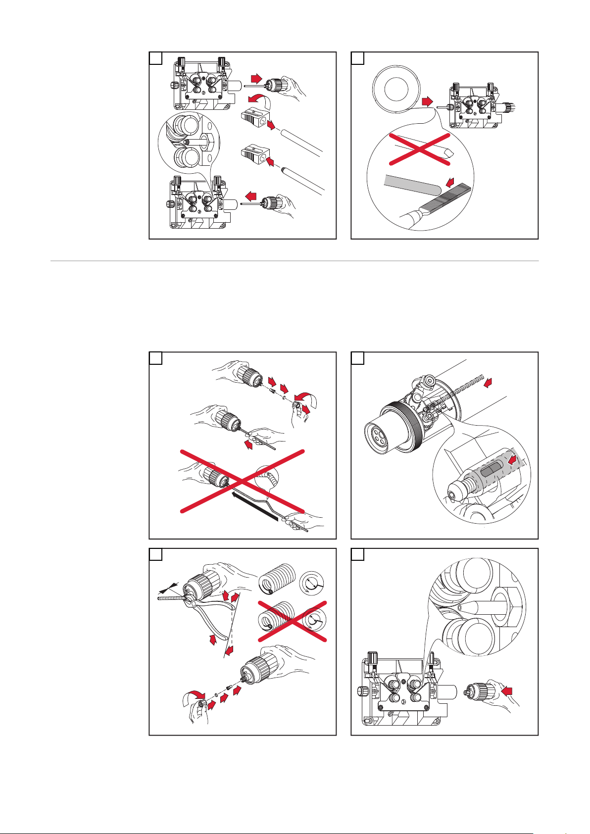
Draht-Führungseinsatz Twin
montieren
16
WICHTIG! Beim Ablängen des Draht-Führungseinsatzes darauf achten, dass
das Kontaktrohr im Rohrbogen fest montiert ist
-
der Draht-Führungseinsatz satt am Kontaktrohr anliegt
-
* Kontaktrohr mit Zentrierbohrung
** Kontaktrohr ohne Zentrierbohrung
WICHTIG! Immer zwei gleiche Kontaktrohre verwenden.
Page 17

Beim Abschließen der Leitungen folgende Reihenfolge einhalten:
1
2
1
2
**
*
1
2
1
0
m
m
.0 in
c
h
1
2
1
2
x.2x.3
x.1
x.3
x.2
x.1
1
2
3
1. Ausblas-Leitung x.1
2. Wasser-Vorlauf x.2 (blau)
3. Wasser-Rücklauf x.3 (rot)
DE
1
3
2
4
5
6
17
Page 18
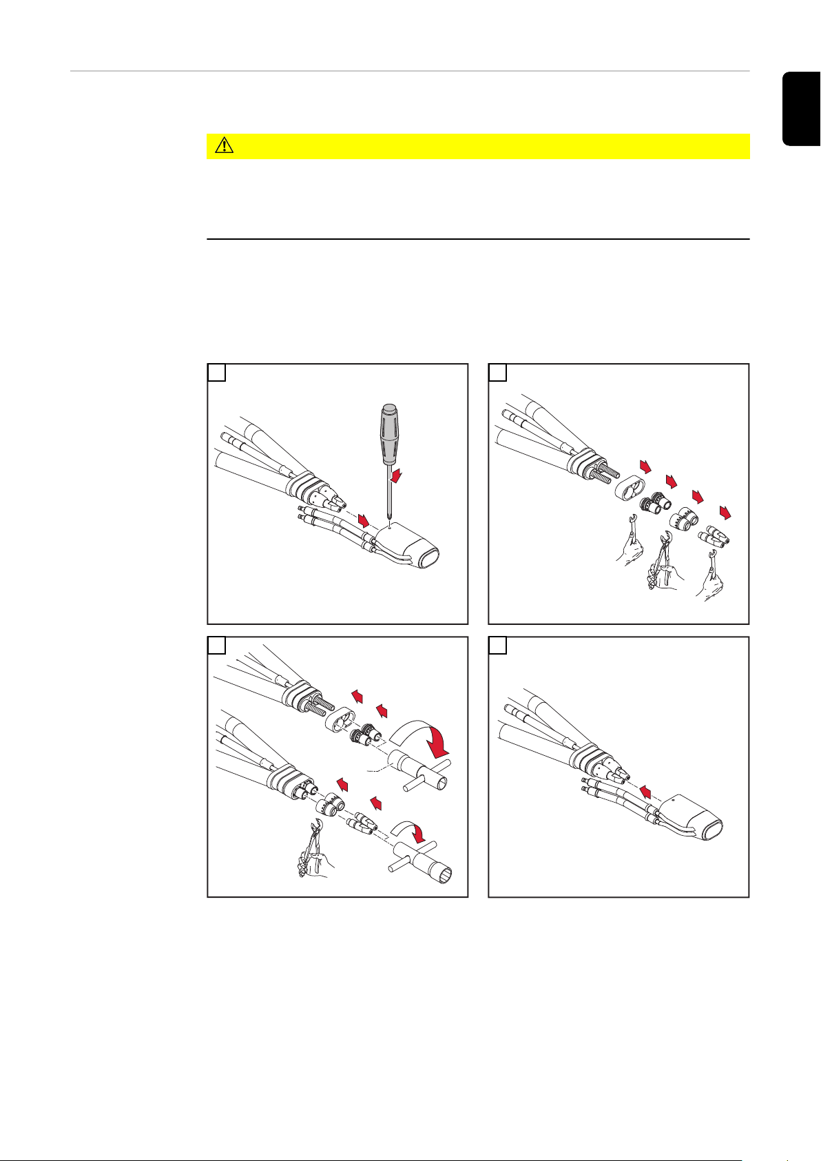
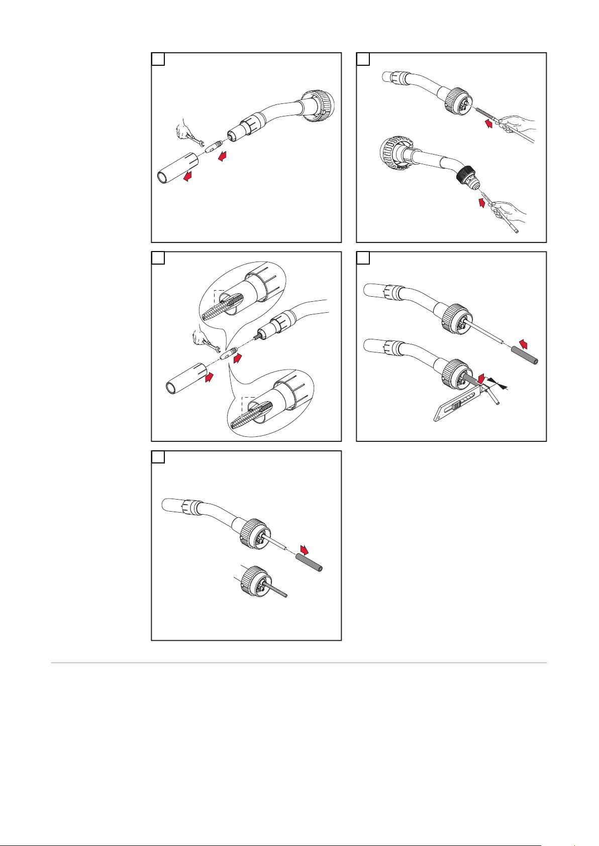
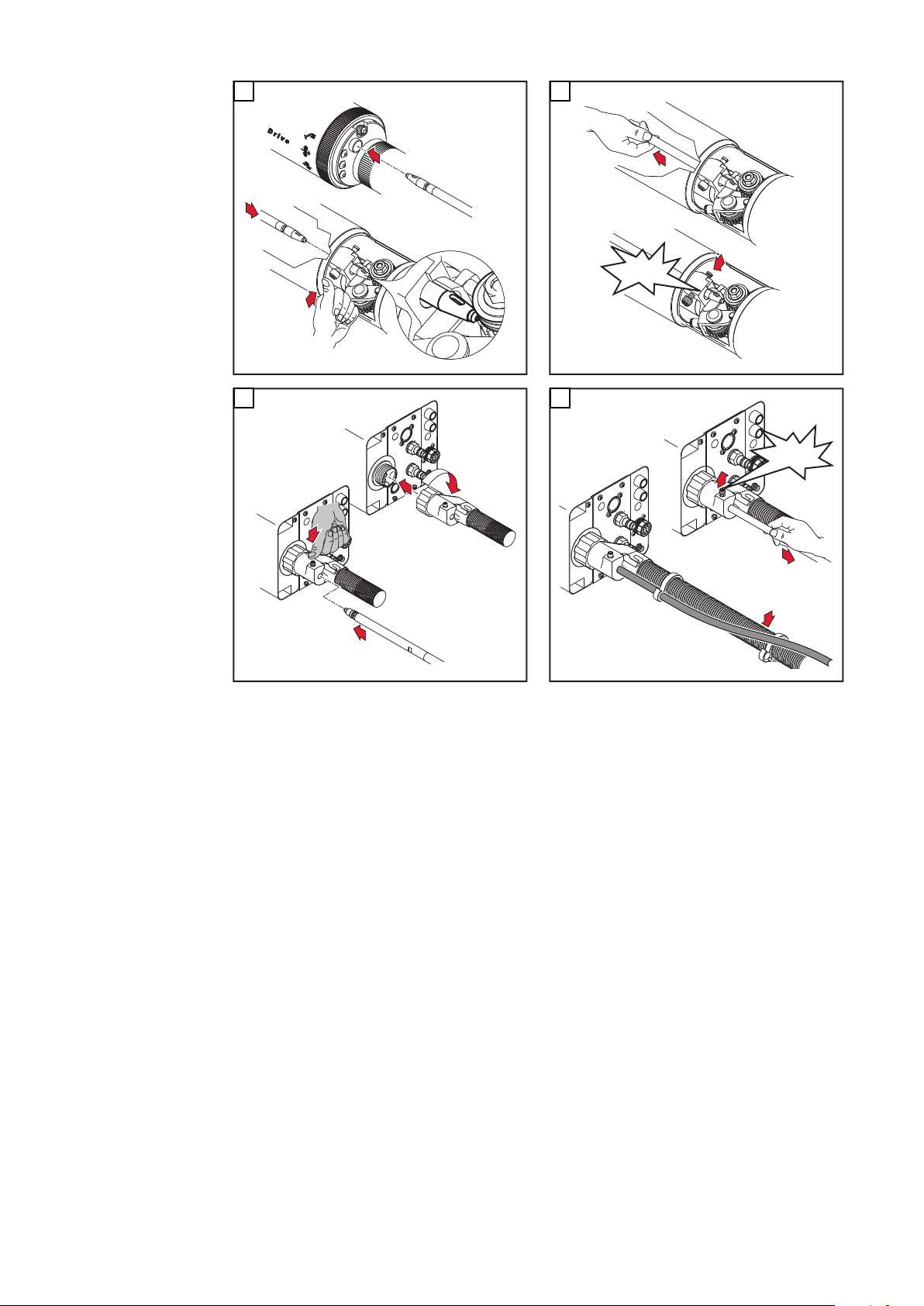
Verschleißteile
2
1
1
2
1
6
7
1
2
3
5
4
an der Antriebseinheit montieren
WICHTIG! Beim Aufsetzen des Rohrbogens auf die Robacta Drive Kuppelstelle
folgendes beachten: Der Draht-Führungseinsatz, muss knickfrei in das Auslaufstück an der Robacta Drive Kuppelstelle gleiten.
VORSICHT!
Gefahr von Kühlmittel-Austritt.
Schwerwiegende Sachschäden können die Folge sein.
Beim Montieren des Rohrbogens, auf festen Sitz der Überwurfmutter ach-
▶
ten.
WICHTIG! Das Lösen und Festziehen der Überwurfmutter wird durch das Spezialwerkzeug „Schlüssel für Überwurfmutter“ erleichtert.
1
3
2
4
18
Page 19

1
2
5
5
3
2
1
4
3
2
1
1
1
1
2
(0 in.)
0 m
m
3
4
1
6
DE
Kunststoff-Seele montieren
VORSICHT!
Gefahr des Knickens der Draht-Führungsseele.
Schwerwiegende Sachschäden können die Folge sein.
Vor dem Einschieben, das Schlauchpaket gerade auslegen.
▶
Vor dem Einfädeln des Schweißdrahtes, Schweißdrahtende abrunden.
▶
1
2
3
4
19
Page 20
1
2
5
3
2
1
1
1
1
(0 in.)
0 m
m
4
2
2
3
3
1
Stahlseele montieren
WICHTIG! Bei der Montage der Stahlseele folgendes beachten:
Nach dem Ablängen der Stahlseele, entstandenen Grat entfernen
-
Vor dem Einschieben der Stahlseele Schlauchpaket gerade auslegen
-
Vor dem Einfädeln des Schweißdrahtes, Schweißdrahtende abrunden
-
1
3
2
4
20
Page 21
1
2
5 6
4
2
3
1
1
1
2
3
4
DE
Kunststoff-Seele montieren
(Euro)
VORSICHT!
Gefahr des Knickens der Draht-Führungsseele.
Schwerwiegende Sachschäden können die Folge sein.
Vor dem Einschieben, das Schlauchpaket gerade auslegen.
▶
Die Draht-Führungsseele möglichst nahe an die Draht-Förderrollen her-
▶
anführen, jedoch nicht berühren lassen.
Vor dem Einfädeln des Schweißdrahtes, Schweißdrahtende abrunden.
▶
* Option Einlaufdüse
1
2
21
Page 22

2
2
3
1
3
2
(.04 - .08 in.)
1-2 mm
*
1
3
2
4
5
1
1
1
2
3
1
4
1
1
4
Stahlseele montieren (Euro)
5
6
WICHTIG! Bei der Montage der Stahlseele folgendes beachten:
Nach dem Ablängen der Stahlseele, entstandenen Grat entfernen
-
Vor dem Einschieben der Stahlseele Schlauchpaket gerade auslegen
-
Vor dem Einfädeln des Schweißdrahtes, Schweißdrahtende abrunden
-
22
1
2
Page 23

3
1
1
2
2
4
5
(0 in.)
0 mm
3
1
1
1
4
DE
5
Externen DrahtFörderschlauch
montieren
VORSICHT!
Gefahr des Knickens der Draht-Führungsseele.
Schwerwiegende Sachschäden können die Folge sein.
Vor dem Einschieben, das Schlauchpaket gerade auslegen.
▶
Vor dem Einfädeln des Schweißdrahtes, Schweißdrahtende abrunden.
▶
* gilt für Stahlseele
VORSICHT!
Gefahr der Beschädigung des Draht-Förderschlauches.
Schwerwiegende Sachschäden können die Folge sein.
Draht-Förderschlauch so am Schlauchpaket befestigen, dass ein Verhängen
▶
an evtl. umliegenden Geräten oder Bauteilen unmöglich ist (Abb.6).
23
Page 24

1
2
4
*
3
1
1
2
4
5
(0 in.)
0
mm
2
2
3
3
4
*
*
3
2
1
1
2
"click"
1
3
2
3
1
2
"click"
2
3
5
4
6
24
Page 25

Brenner an-
1
4
3
2
*
5
6
4
5
3
1
2
*
1
1
2
7
5
6
2
3
4
*
schließen
WICHTIG! Beim Anschließen des Schweißbrenners, die Anschlüsse
Schweißbrenner „1“ und „2“ mit dem jeweils dazugehörigen Drahtvorschub verbinden und kontrollieren ob
sämtliche Anschlüsse fest angeschlossen sind
-
sämtliche Kabel, Leitungen, und Schlauchpakete unbeschädigt und korrekt
-
isoliert sind.
* Option Brenner ausblasen
WICHTIG! Bei Nichtverwendung der Option Brenner ausblasen, auf dichten Verschluss der Ausblasleitung achten.
DE
1
3 4
2
25
Page 26

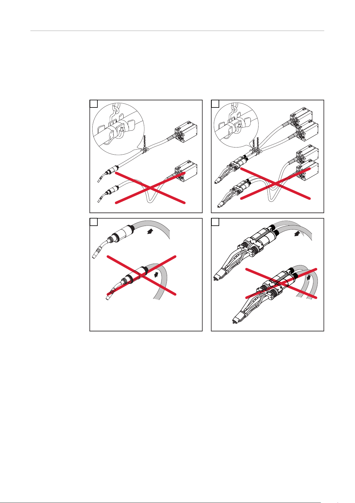
Richtige Verlegung des Roboter-Schlauchpaketes
Um eine optimale Drahtförderung zu erreichen, bei der Verlegung des Schlaupaketes folgendes beachten:
Schlauchpakt nicht knicken
-
Schlauchpaket möglichst geradlinig auslegen
-
Schlauchpaket nicht überstrecken, vor allem im Roboterbetrieb
-
Biegeradien im Schlauchpaket so groß wie möglich halten
-
Balancer und Schlauchpaket- Halterungen verwenden (z.B.: Schlauchpaket-
-
Halterung Universal)
1 2
3 4
26
Page 27
Bedienelemente
1
3
2
1 2 3 4
5
2,5
1
Fdi
(m/min)
(ipm)
t (s)
2
1
1
*
und Funktionen
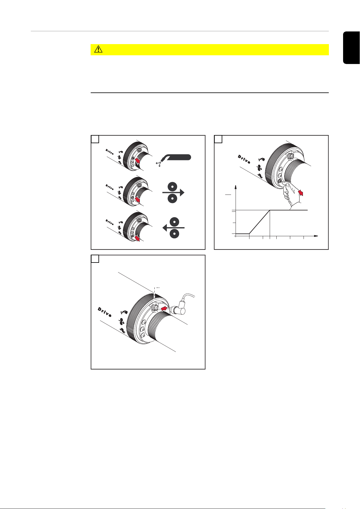
VORSICHT!
Verletzungsgefahr durch austretenden Schweißdraht.
Schwerwiegende Personenschäden können die Folge sein.
Schweißbrenner von Gesicht und Körper fernhalten.
▶
Vor dem Einfädeln des Schweißdrahtes, Schweißdrahtende abrunden.
▶
WICHTIG! Der beschriebene Ablauf in Bild 2, gilt nicht für die Taste Draht-Rücklauf und allgemein nicht für die Stromquellen TS/TPS 330/450.
* Anschlussbuchse CrashBox
DE
1
3
2
27
Page 28
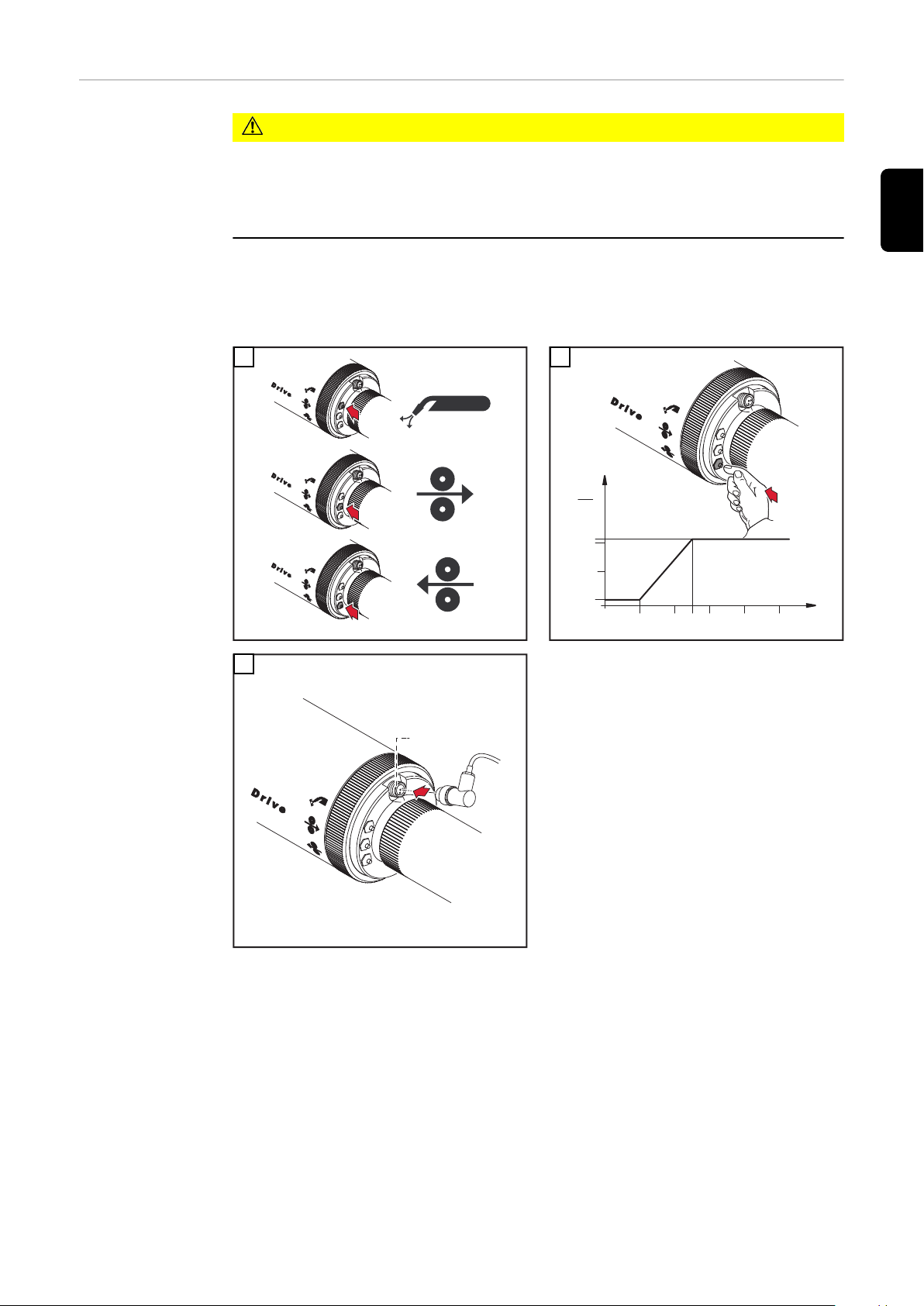
Einstellschraube
1
2
3
0,5 1,5 2 3,5
justieren
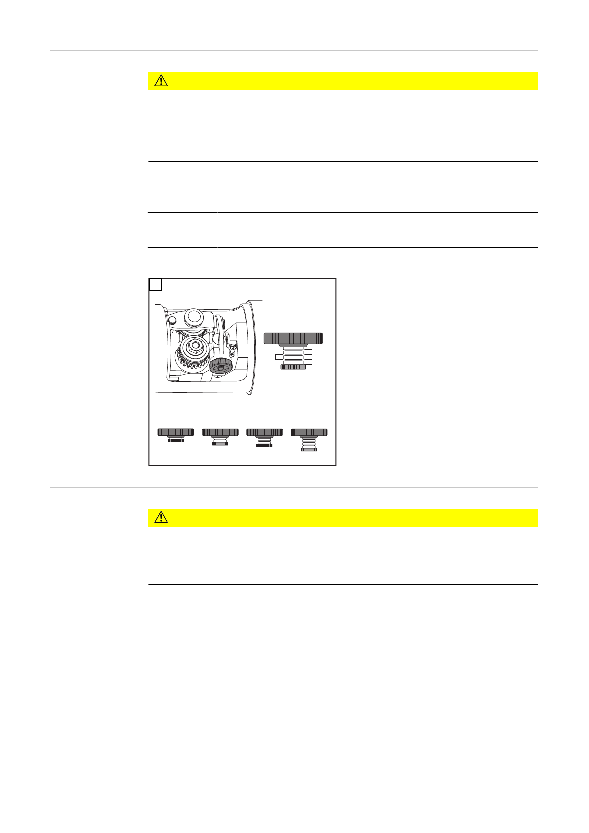
VORSICHT!
Verletzungsgefahr durch rotierende Vorschubrollen.
Schwerwiegende Personenschäden können die Folge sein.
Nicht in die Vorschubrollen greifen.
▶
Das Justieren der Einstellschraube ist nur bei eingefädeltem Schweißdraht
▶
zulässig
Sichtbare Teilungen bei eingestelltem Anpressdruck für den verwendeten
Schweißdraht:
0,5 - 1,5 Al-, AlSi, AlMg
2,0 - 3,5 CuSi-, Fe-, CrNi
3,5 max. Anpressdruck
1
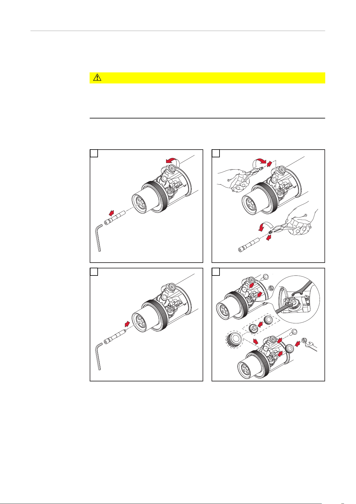
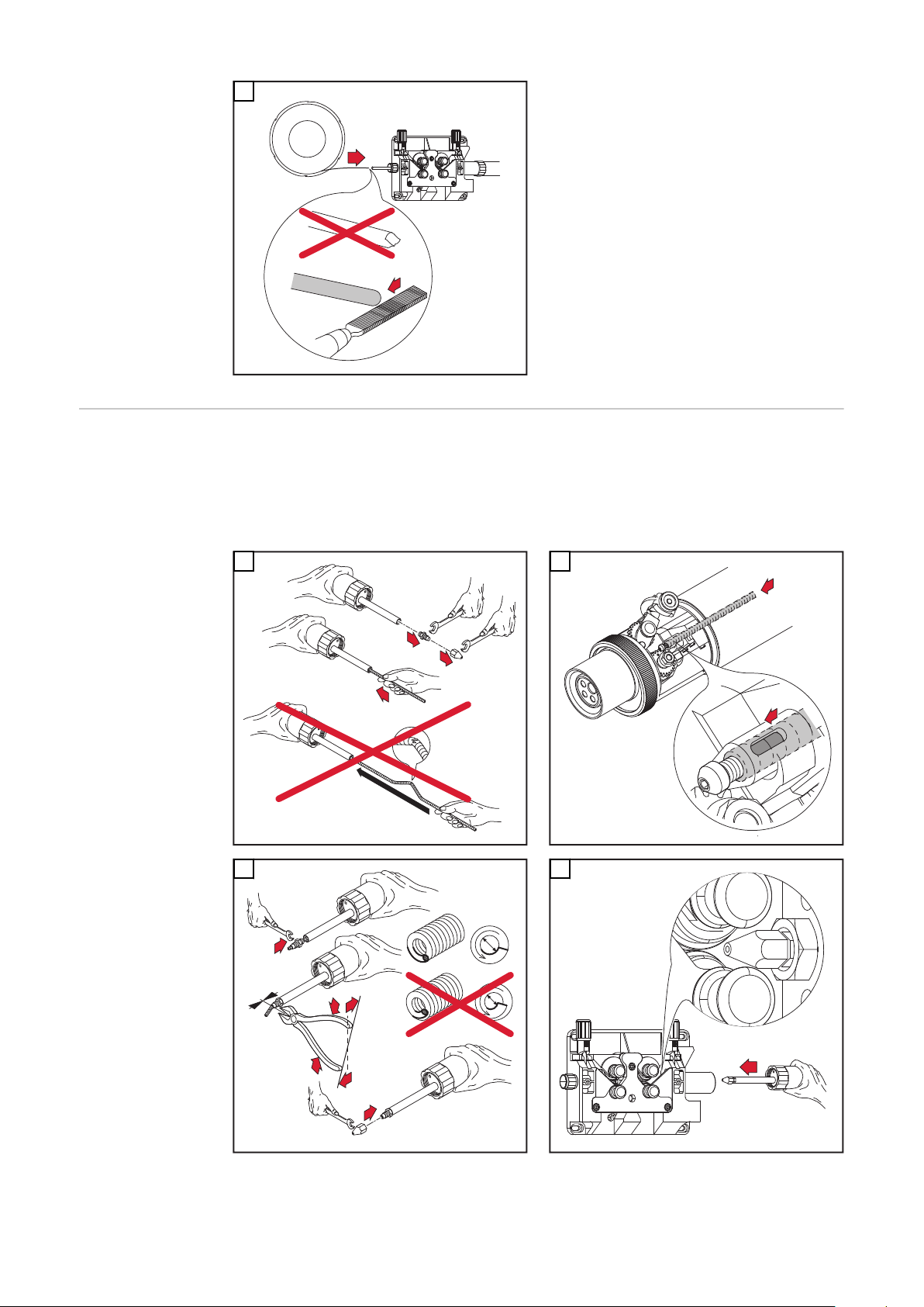
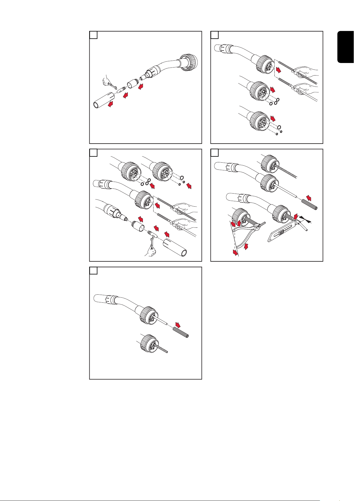
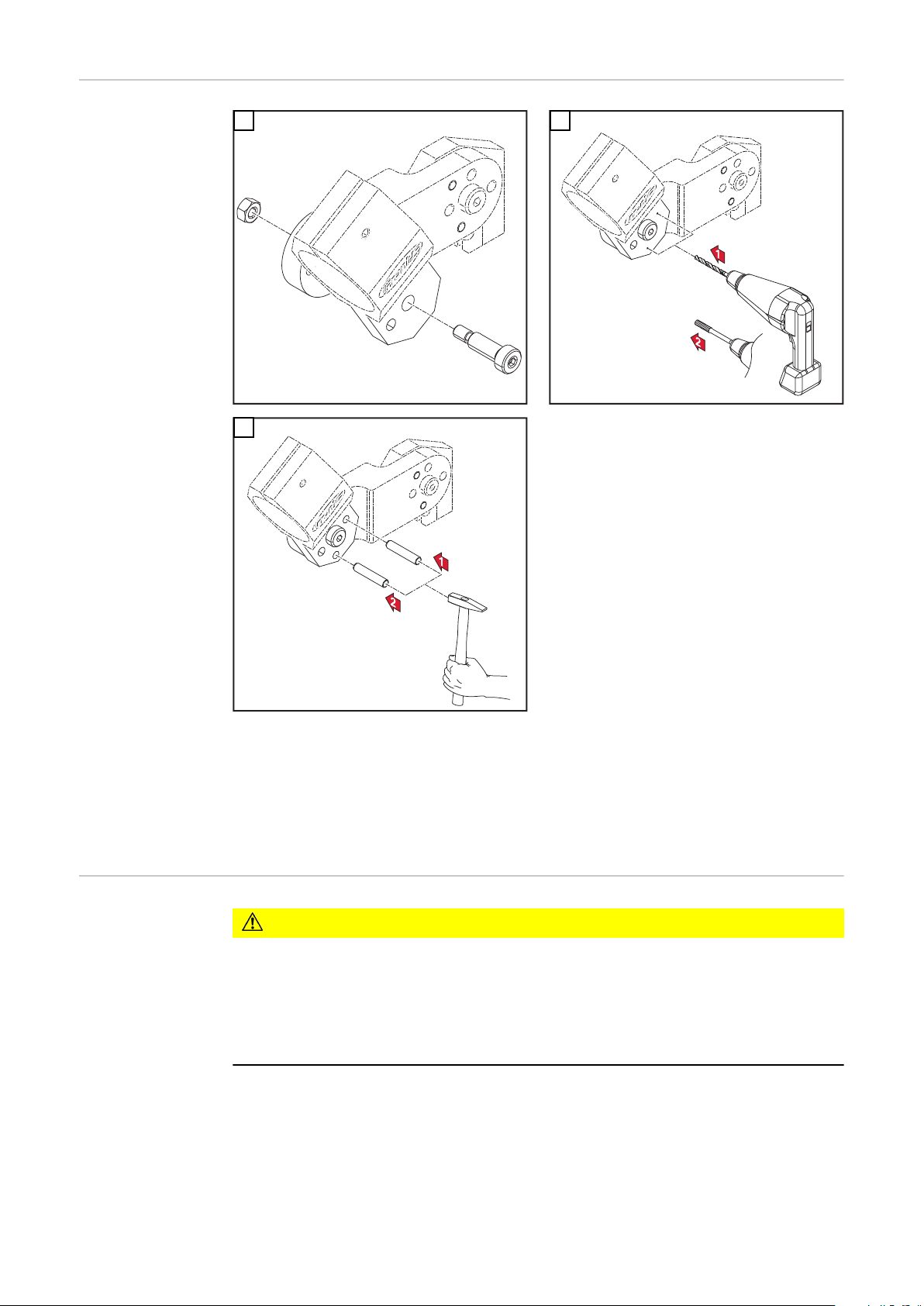
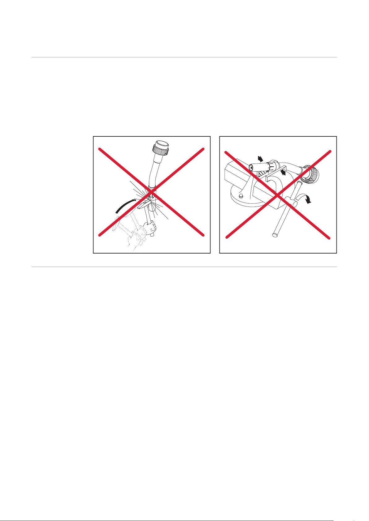
Verschleißteile
am Rohrbogen
wechseln
Verbrühungsgefahr durch heißes Kühlmittel.
Schwere Verbrühungen können die Folge sein.
▶
WICHTIG! Kühlmittelaustritt vermeiden. Beim Abnehmen des Rohrbogens von
der Robacta Drive Kuppelstelle folgendes beachten.
-
-
-
-
VORSICHT!
Vor Abnehmen des Rohrbogens Netzschalter an der Stromquelle in Stellung
„O“ schalten.
Schweißdraht beim Kontaktrohr ablängen
Rohrbogen hineindrücken und halten
Überwurfmutter vollständig lösen
Rohrbogen mit schneller Bewegung gerade abziehen
28
Page 29
1
2
3
1
1
2
3
6
3
5
1
2
4
1
0 mm
.0 inch
2
3
3
2
2
1
2
DE
3
4
5
29
Page 30

Pflege, Wartung und Entsorgung
Allgemeines Regelmäßige und vorbeugende Wartung des Schweißbrenners sind wesentliche
Faktoren für einen störungsfreien Betrieb. Der Schweißbrenner ist hohen Temperaturen und starker Verunreinigung ausgesetzt. Daher benötigt der Schweißbrenner eine häufigere Wartung als andere Komponenten des Schweißsystems.
WICHTIG! Vermeiden Sie beim Entfernen von Schweißspritzern Riefen und Kratzer. Darin könnten sich im weiteren Betrieb entstehende Schweißspritzer nachhaltig festsetzen.
Den Rohrbogen keinesfalls biegen
-
Bei jeder Inbetriebnahme
Bei jeder Inbetriebnahme:
Kontaktrohr kontrollieren
-
ausgeschliffenes Kontaktrohr austauschen
-
Gasdüse von Schweißspritzern befreien (z.B. manuell, durch Ausblasen oder
-
automatisiert mit Robacta Reamer oder Robacta TC 1000)
Bei nicht entfernbaren Verunreinigungen im Steckbereich Gasdüse austau-
-
schen
* Spritzerschutz oder Isolationen auf Beschädigung prüfen
Wassergekühlte Schweißbrenner:
Wasseranschlüsse auf Dichtheit prüfen
-
Wasserrückfluss-Menge im Kühlmittel-Behälter überwachen, ggf. Kühlgerät
-
entlüften
30
Page 31

2
1
Robacta 700
1
2
*
*
*
1
DE
Bei jedem Austausch der
Draht-Spule
Empfohlen: Draht-Führungsseele austauschen
-
Draht-Förderrollen kontrollieren und gegebenenfalls wenden oder austau-
-
schen
Draht-Förderschlauch und Antriebseinheit mit reduzierter Pressluft reinigen
-
Verschleißteile vor dem Einbau reinigen
-
31
Page 32
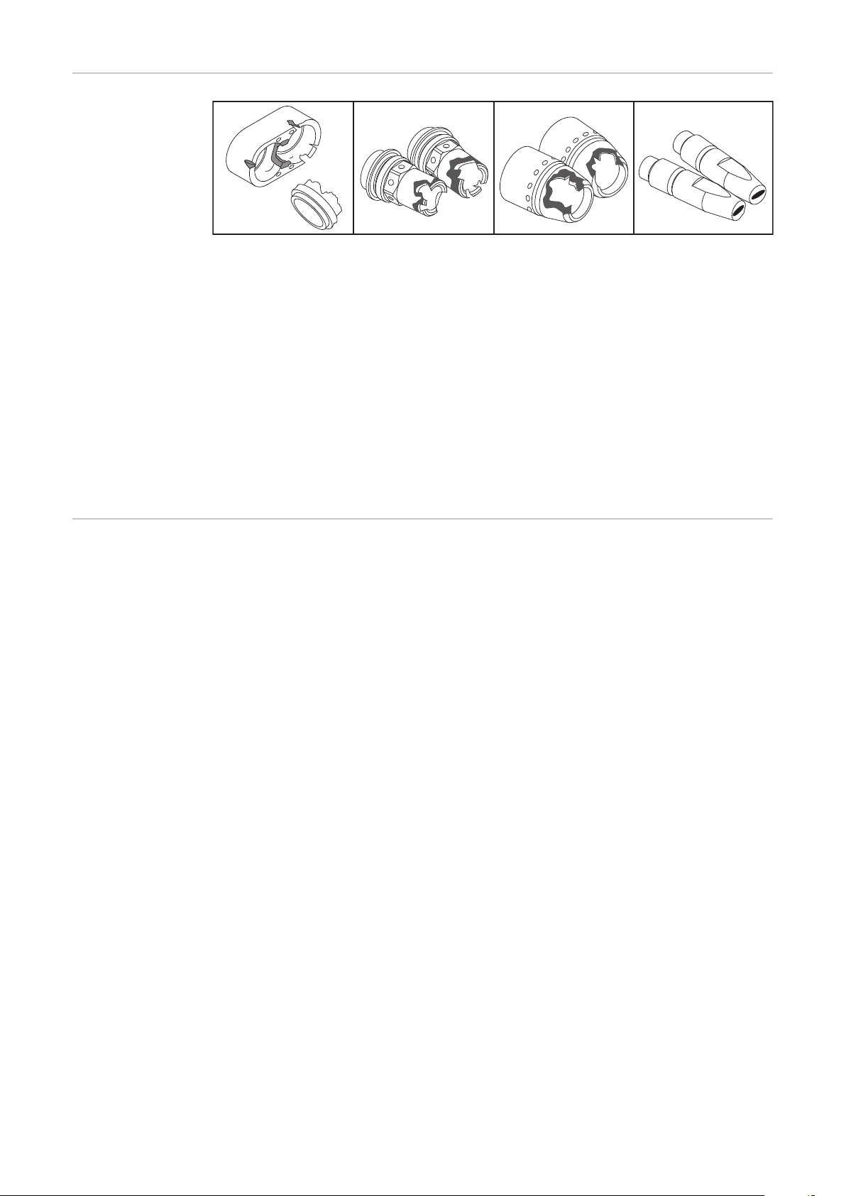
Erkennen von
1.
2.
3.
4.
defekten Verschleißteilen
Isolierteile
1.
Einkerbungen
-
abgebrannter oder eingerissener Mittelsteg
-
angeschmorte oder abgerissene Ansätze
-
Düsenstöcke
2.
Einkerbungen und Einbrand an der Vorderkante
-
stark mit Schweißspritzern behaftet
-
Spritzerschutz
3.
abgebrannte Außenkanten, Einkerbungen
-
Kontaktrohre
4.
ausgeschliffene (ovale) Drahteintritts- und Drahtaustritts-Bohrungen
-
stark mit Schweißspritzern behaftet
-
Einbrand an der Kontaktrohr-Spitze
-
Entsorgung Die Entsorgung nur gemäß den geltenden nationalen und regionalen Bestimmun-
gen durchführen.
32
Page 33

Fehlerdiagnose, Fehlerbehebung
DE
Fehlerdiagnose,
Fehlerbehebung
kein Schweißstrom
Netzschalter eingeschaltet, Anzeigen an der Stromquelle leuchten, Schutzgas
vorhanden
Ursache:
Behebung:
Ursache:
Behebung:
Robacta Drive arbeitet nicht
Netzschalter eingeschaltet, Anzeigen an der Stromquelle leuchten
Ursache:
Behebung:
Ursache:
Behebung:
Ursache:
Behebung:
Masseanschluss falsch
Masseanschluss und Klemme auf Polarität überprüfen
Stromkabel im Robacta Drive Schlauchpaket unterbrochen
Service-Dienst verständigen
Steuerstecker nicht eingesteckt
Steuerstecker einstecken
Steuerleitung defekt
Service-Dienst verständigen
Verbindungs-Schlauchpaket defekt oder nicht korrekt angeschlossen
(nicht bei TPS 2700)
Verbindungs-Schlauchpaket überprüfen
Ursache:
Behebung:
kein Schutzgas
alle anderen Funktionen vorhanden
Ursache:
Behebung:
Ursache:
Behebung:
Ursache:
Behebung:
Ursache:
Behebung:
Ursache:
Behebung:
PushPull-Unit defekt
Service-Dienst verständigen
Gasflasche leer
Gasflasche wechseln
Gasdruckminderer defekt
Gasdruckminderer tauschen
Gasschlauch nicht montiert oder schadhaft, geknickt
Gasschlauch montieren, ausbiegen oder tauschen
Schweißbrenner defekt
Schweißbrenner austauschen
Gas-Magnetventil defekt
Gas-Magnetventil austauschen
33
Page 34

schlechte Schweißeigenschaften
Ursache:
Behebung:
falsche Schweißparameter
Einstellungen überprüfen
Ursache:
Behebung:
Ursache:
Behebung:
Ursache:
Behebung:
Ursache:
Behebung:
Ursache:
Behebung:
Ursache:
Behebung:
Ursache:
Behebung:
Masseverbindung schlecht
guten Kontakt zum Werkstück herstellen
kein oder zu wenig Schutzgas
Druckminderer, Gasschlauch, Gas-Magnetventil und Brenner-Gasan-
schluss überprüfen. Bei gasgekühlten Schweißbrennern Gasabdichtung überprüfen, geeignete Draht-Führungsseele verwenden.
Schweißbrenner undicht
Schweißbrenner austauschen
zu großes oder ausgeschliffenes Kontaktrohr
Kontaktrohr wechseln
falsche Drahtlegierung oder falscher Drahtdurchmesser
eingelegte Drahtrolle kontrollieren; Verschweißbarkeit des Grund-
Werkstoffes prüfen
Schutzgas für Drahtlegierung nicht geeignet
korrektes Schutzgas verwenden
Ungünstige Schweißbedingungen: Schutzgas verunreinigt (Feuchtigkeit, Luft), mangelhafte Gasabschirmung (Schmelzbad „kocht“, Zugluft), Verunreinigungen im Werkstück (Rost, Lack, Fett)
Schweißbedingungen optimieren
Ursache:
Behebung:
Ursache:
Behebung:
Ursache:
Behebung:
Ursache:
Behebung:
Ursache:
Behebung:
Ursache:
Behebung:
Schweißspritzer in der Gasdüse
Schweißspritzer entfernen
Turbulenzen auf Grund zu hoher Schutzgasmenge
Schutzgas-Menge reduzieren, empfohlen:
Schutzgas-Menge (l/min) = Drahtdurchmesser (mm) x 10
(z.B. 16 l/min für 1,6 mm Schweißdraht)
zu großer Abstand zwischen Schweißbrenner und Werkstück
Abstand zwischen Schweißbrenner und Werkstück reduzieren (emp-
fohlen: 10 - 15 mm)
zu großer Anstellwinkel des Schweißbrenners
Anstellwinkel des Schweißbrenners reduzieren
Draht-Förderkomponenten mit falschem Durchmesser
Draht-Förderkomponenten mit korrektem Durchmesser verwenden
Falscher PushPull-Abgleich
Beim PushPull-Abgleich die richtige Nummer für die PPU-Unit (Ro-
bacta Drive) auswählen. Siehe Bedienungsanleitung PPU-Unit
34
Ursache:
Gasverlust oder Fremdluft
Page 35
Behebung:
Kurze Lebensdauer des Kontaktrohres
Ursache:
Behebung:
Dichtheit Ausblasleitung und Ausblasventil prüfen. Verschluss der
Ausblasleitung überprüfen (Stecknippel)
Falsche Vorschubrollen
Korrekte Vorschubrollen verwenden
DE
Ursache:
Behebung:
Ursache:
Behebung:
Ursache:
Behebung:
Ursache:
Behebung:
Ursache:
Behebung:
Ursache:
Behebung:
HINWEIS!
Abrieb der Drahtelektrode infolge von zu starkem Anpressdruck an
den Vorschubrollen
Anpressdruck an den Vorschubrollen reduzieren
Drahtelektrode verunreinigt / angerostet
Hochwertige Drahtelektrode ohne Verunreinigungen verwenden
Unbeschichtete Drahtelektrode
Drahtelektrode mit geeigneter Beschichtung verwenden
Falsche Dimension des Kontaktrohres
Kontaktrohr korrekt dimensionieren
Zu lange Einschaltdauer des Schweißbrenners
Einschaltdauer herabsetzen oder leistungsfähigeren Schweißbrenner
verwenden
Kontaktrohr überhitzt. Keine Wärmeableitung auf Grund zu losen
Sitzes des Kontaktrohres
Kontaktrohr festziehen
Bei CrNi-Anwendungen kann auf Grund der Oberflächen-Beschaffenheit der
CrNi-Drahtelektrode ein höherer Kontaktrohr-Verschleiß auftreten.
Draht-Fördertasten funktionieren nicht
Ursache:
Behebung:
Ursache:
Behebung:
Steckerverbindungen „Steuerleitung / Stromquelle“ fehlerhaft
Steckerverbindung überprüfen / Stromquelle bzw. Robacta Drive
zum Service
Steuerleitung ist defekt
Steuerleitung austauschen / Robacta Drive zur Reparatur
35
Page 36

schlechte Drahtförderung
Ursache:
Behebung:
Bremse zu fest eingestellt
Bremse lockerer einstellen
Ursache:
Behebung:
Ursache:
Behebung:
Ursache:
Behebung:
Ursache:
Behebung:
Ursache:
Behebung:
Ursache:
Behebung:
Ursache:
Behebung:
Bohrung des Kontaktrohres verlegt
Kontaktrohr austauschen
Draht-Förderseele oder Draht-Führungseinsatz im Schweißbrenner
defekt
Draht-Förderseele und Draht-Führungseinsatz auf Knicke, Verschmutzung, etc. prüfen
Draht-Vorschubrollen für verwendete Drahtelektrode nicht geeignet
passende Draht-Vorschubrollen verwenden
falscher Anpressdruck der Draht-Vorschubrollen
Anpressdruck optimieren
Draht-Vorschubrollen verunreinigt oder beschädigt
Draht-Vorschubrollen reinigen oder austauschen
Draht-Führungsseele oder Draht-Führungseinsatz verlegt oder geknickt
Draht-Führungsseele oder Draht-Führungseinsatz austauschen
Falsche Dimension der Draht-Führungsseele, des Draht-Führungseinsatzes oder der Draht-Einlaufdüse
Draht-Führungsseele, Draht-Führungseinsatz oder Draht-Einlaufdüse
korrekt dimensionieren
Ursache:
Behebung:
Ursache:
Behebung:
Ursache:
Behebung:
Ursache:
Behebung:
Ursache:
Behebung:
Ursache:
Behebung:
Draht-Führungsseele wurde beim Einschieben geknickt
Draht-Führungsseele beim Einschieben nur in der Nähe des Einlauf-
rohres anfassen
AlSi Schweißdraht: Beschädigung des Drahtes durch den Bronzeeinsatz
Teflonseele muss bis zum Kontaktrohr reichen
Draht-Führungsseele nach dem Ablängen zu kurz
Draht-Führungsseele austauschen und auf korrekte Länge kürzen
Abrieb des Schweißdrahtes infolge von zu starkem Anpressdruck an
den Draht-Förderrollen
Anpressdruck an den Draht-Förderrollen reduzieren
Schweißdraht verunreinigt / angerostet
Hochwertigen Schweißdraht ohne Verunreinigungen verwenden
Robacta Drive fördert zu schnell oder zu langsam
Beim PushPull-Abgleich die richtige Nummer für die PPU-Unit (Ro-
bacta Drive) auswählen. Siehe Bedienungsanleitung PPU-Unit
36
Page 37

Porosität der Schweißnaht
Ursache:
Behebung:
Spritzerbildung in der Gasdüse, dadurch unzureichender Gasschutz
der Schweißnaht
Schweißspritzer entfernen
DE
Ursache:
Behebung:
Ursache:
Behebung:
Ursache:
Behebung:
Ursache:
Behebung:
Ursache:
Behebung:
Ursache:
Behebung:
Ursache:
Behebung:
Löcher im Schutzgas-Schlauch oder ungenaue Anbindung des
Schutzgas-Schlauches
Schutzgas-Schlauch austauschen
O-Ringe an den Anschlüssen sind zerschnitten oder defekt
O-Ringe austauschen
Feuchtigkeit / Kondensat in der Schutzgas-Leitung
Schutzgas-Leitung trocknen
Zu starke oder zu geringe Schutzgas-Strömung
Schutzgas-Strömung korrigieren
Ungenügende Schutzgas-Menge zu Schweißbeginn oder Schweißende
Gas-Vorströmung und Gas-Nachströmung erhöhen
Rostige oder schlechte Qualität der Drahtelektrode
Hochwertige Drahtelektrode ohne Verunreinigungen verwenden
Gilt für gasgekühlte Schweißbrenner: Schutzgas-Austritt bei nicht
isolierten Draht-Führungsseelen
Bei gasgekühlten Schweißbrennern nur Draht-Führungsseelen isoliert
verwenden
Ursache:
Behebung:
Schweißbrenner wird sehr heiß
Ursache:
Behebung:
Ursache:
Behebung:
Ursache:
Behebung:
Ursache:
Behebung:
Zu viel Trennmittel aufgetragen
Überschüssiges Trennmittel entfernen / weniger Trennmittel auftra-
gen
Überwurfmutter am Zentralanschluss locker
Überwurfmutter festziehen
Schweißbrenner wurde über die maximale Ampereanzahl hinaus betrieben.
Schweißleistung herabsetzen oder leistungsfähigeren Schweißbrenner verwenden
Schweißbrenner zu schwach dimensioniert
Einschaltdauer und Belastungsgrenzen beachten
nur bei Wasserkühlung: Wasserdurchfluss zu gering
Wasserstand, Wasser-Durchflussmenge, Wasserverschmutzung, Ver-
legung des Schlauchpaketes etc. kontrollieren
37
Page 38

Technische Daten
Ø
Ø
Ø
Rohrbögen Symbolerklärung:
wassergekühlt
X Einschaltdauer in %
ED* Einschaltdauer
X / I
40°C)
M21 (EN 439)
X / I
40°C)
C1 (EN 439)
(10 min /
max
(10 min /
max
I
max
(M6) mit Kontaktrohr M6
(M8) mit Kontaktrohr M8
Spannungsbemessung (V-Peak):
für maschinellgeführte Schweißbrenner: 141 V
-
Das Produkt entspricht den Anforderungen laut Norm IEC 60974-7.
Robacta 160 Robacta 280 Robacta 300 Robacta 400
[%] / [A]
[%] / [A]
[%] / [A]
[%] / [A]
[%] / [A]
[%] / [A]
max. Schweißstrom in A
Elektrodendurchmesser
-
100 / 160
-
100 / 160
-
100 / 280
-
100 / 280
-
100 / 350
-
100 / 350
-
100 / 250
(M6); 400
(M8)
-
100 / 250
(M6); 400
(M8)
X / I
40°C)
M21 (EN 439)
X / I
40°C)
C1 (EN 439)
38
(10 min /
max
(10 min /
max
[mm]
[in.]
Robacta 500 Robacta 700 Robacta 700
[%] / [A]
[%] / [A]
[%] / [A]
[%] / [A]
[%] / [A]
[%] / [A]
[mm]
[in.]
0,8 - 1,2
.031 - .047
-
100 / 500
-
100 / 500
0,8 - 1,6
.031 - .063
0,8 - 1,2
.031 -. 047
-
100 / 700
-
100 / 700
1,0 - 1,6
.039 - .063
0,8 - 1,2
.031 - .047
TIME
-
100 / 700
-
100 / 700
1,0 - 1,6
.039 - .063
0,8 - 1,2
.031-.047
Robacta 2500
-
100 / 250
-
100 / 250
0,8 - 1,2
.031-.047
Page 39

Ø
Ø
Ø
Ø
X / I
(10 min /
max
40°C)
M21 (EN 439)
Robacta 5000 Robacta 7000 Rob. 500-M
(Con-Drive)
[%] / [A]
[%] / [A]
[%] / [A]
-
100 / 500
-
100 / 700
-
100 / 500
Laser HD/W
-
100 / 250
DE
X / I
(10 min /
max
40°C)
C1 (EN 439)
X / I
(10 min /
max
40°C)
M21 (EN 439)
X / I
(10 min /
max
40°C)
M21 (EN 439)
[%] / [A]
[%] / [A]
[%] / [A]
[mm]
[in.]
-
100 / 500
0,8 - 1,6
.031 - .063
Robacta Twin
Single 300
[%] / [A]
[%] / [A]
[%] / [A]
[mm]
[in.]
-
100 / 300
0,8 - 1,6
.031 - .063
Robacta Twin
900 Compact
[%] / [A]
[%] / [A]
[%] / [A]
-
100 / 900
(2x450)
-
100 / 700
1,0 - 1,6
.039 - .063
Robacta Twin
500
-
100 / 500
(2x250)
1,0 - 1,6
.039 - .063
Robacta Twin
Compact
PRO
-
100 / 900
(2x450)
-
100 / 500
0,8 - 1,6
.031 - .063
Robacta Twin
600
-
100 / 600
(2x300)
0,8 - 1,6
.031 - .063
-
100 / 250
1,0 - 1,6
.039 - .063
Robacta Twin
900
-
100 / 900
(2x450)
1,0 - 1,6
.039 - .063
X / I
40°C)
M21 (EN 439)
X / I
(10 min /
max
(10 min /
max
40°C)
C1 (EN 439)
[mm]
[in.]
1,0 - 1,6
.039 - .063
MTB 500i
W/R
[%] / [A]
[%] / [A]
[%] / [A]
[%] / [A]
[%] / [A]
[%] / [A]
[mm]
[in.]
-
100 / ED* 500
-
100 / ED* 500
1,0 - 1,6
.039 - .063
1,0 - 1,6
.039 - .063
MTB 330i
W/R
-
100 / ED* 330
-
100 / ED* 330
0,8 - 1,6
.032 -. 063
MTB 500d
W/R
-
100 / ED* 500
-
100 / ED* 500
1,0 - 1,6
.039 - .063
MTB 330d
W/R
-
100 / ED* 330
-
100 / ED* 330
0,8 - 1,6
.031-.063
39
Page 40

Drive -
Ø
Ø
Schlauchpakete
Symbolerklärung:
wassergekühlt
Schlauchpaket-Länge
X Einschaltdauer in %
X / I
(10 min /
max
40°C)
M21 (EN 439)
X / I
(10 min /
max
40°C)
C1 (EN 439)
I
max
max. Schweißstrom in A
Elektrodendurchmesser
* geringste Kühlleistung laut Norm IEC 60974-2,
abhängig von der Schlauchpaket-Länge
Spannungsbemessung (V-Peak): 141 V
Das Produkt entspricht den Anforderungen laut Norm IEC 60974-7.
Robacta Drive Robacta Drive HW
[%] / [A]
[%] / [A]
[%] / [A]
[%] / [A]
[%] / [A]
[%] / [A]
[mm]
[in.]
-
100 / 500
-
100 / 500
0,8 - 1,6
.031 - .063
-
100 / 500
-
100 / 500
1,0 - 1,6
.04 - .06
P
*
min
[m] ([W])
[m] ([W])
[m] ([W])
[ft.] ([W])
[ft.] ([W])
[ft.] ([W])
1,5 (700) / 1,75 (800) / 2,0 (850)
2,5 (1000) / 3,5 (1300) / 4,25
(1500) /
5,25 (1750) / 6,25 (2050) / 8,25
(2600)
4.9 (700) / 5.7 (800) / 6.6 (850) /
8.2 (1000) / 11.5 (1300) / 13.9
2,5 (1000) / 8,25 (2600)
8.2 (1000) / 27 (2600)
(1500) /
17.2 (1750) / 20.5 (2050) / 27
(2600)
Q
min
P
min
Q
min
[L/min]
[gal./min]1.26 [US]
[bar]
[psi.]
[bar]
[psi.]
3
43
5,5
79.74
1
.26 [US]
3
43
5,5
79.74
[V] DC 42 42
[A] 2,15 2,15
[min]
[ipm.]
0,5 - 22
16.69 - 866.14
0,5 - 10
19.69 - 393.7.74
40
Page 41
Ø
X / I
40°C)
M21 (EN 439)
X / I
40°C)
(10 min /
max
(10 min /
max
C1 (EN 439)
P
*
min
Robacta Drive Twin Robacta Drive Twin Robacta
[%] / [A]
[%] / [A]-100 / 900 (2x450)
[%] / [A]
[%] / [A]-100 / 900 (2x450)
[mm]
[in.]
[m] ([W])
[m] ([W])
[ft.] ([W])
[ft.] ([W])
0,8 - 1,2
.031 - .047
1,6 (1400) / 2,6
(1900) / 3,6 (2300)
5.2 (1400) / 8.5
(1900) / 11.8 (2300) /
100 / 720 (2x360)
100 / 720 (2x360)
0,8 - 1,2
1,0 - 1,6
.031 - .047
4,5 (1950) / 5,25
(2250) / 6,25 (2500) /
8,25 (3100)
13.9 (1950) / 17.2
(2250) /
20.5. (2500) / 27 (3100)
Drive CW
DE
-
-
-
-
.04 - .06
8,25
27
Q
min
P
min
Q
min
[L/min]
[gal./min]1.26 [US]
[bar]
[psi.]
[bar]
[psi.]
3
43
5,5
79.74
1
1.26 [US]
3
43
5,5
79.74
-
-
-
-
-
-
[V] DC 42 42 42
[A] 2,15 2,1 2,15
[min]
[ipm.]
0,5 - 22
16.69 - 866.14
0,5 - 22
16.69 - 866.14
0,5 - 10
19.7 - 393.7
41
Page 42

42
Page 43

Contents
Safety 44
Safety 44
General 46
General remarks 46
Original equipement and tools 46
Installation and commissioning 47
Fitting the mounting bracket (standard) 47
Fitting the mounting bracket (individually) 48
Robacta torch necks - dismantling and assembling 48
Dismantling and assembling Robacta Twin torch necks 49
Dismantling and assembling Robacta Twin Compact Pro torch necks 51
Replacing welding torch wearing parts - Robacta 51
Replacing welding torch wearing parts - Robacta / MTW 500-M 52
Replacing welding torch wearing parts - Robacta Twin 53
Robacta Twin Compact Pro - Replacing components 54
Replacing the gas nozzle Robacta 160 / 300 / 500 Robacta 700 / 700 Time MTW 500-M
Con-Drive
Assemble Wire Guide Insert 55
Assemble Twin Wire Guide Insert 56
Install Wear Parts on Drive Unit 57
Assemble the plastic inner liner 59
Assemble the steel inner liner 60
Assemble the plastic inner liner (Euro) 61
Assemble the steel inner liner (Euro) 62
Assemble External Wire Feed Tube 63
Connect Torch 65
Correct laying of the robot hose pack 66
Operating Elements and Functions 67
Adjust Setting Screw 68
Replace Wear Parts on Torch Neck 68
Care, maintenance and disposal 70
General remarks 70
Every start-up 70
Every time the wire spool is exchanged 71
Recognising faulty wearing parts 72
Disposal 72
Troubleshooting 73
Troubleshooting 73
Technical data 78
Torch necks 78
Drive hosepacks 80
EN
55
43
Page 44

Safety
Safety
WARNING!
Danger from incorrect operation and work that is not carried out properly.
This can result in serious personal injury and damage to property.
All the work and functions described in this document must only be carried
▶
out by technically trained and qualified personnel.
Read and understand this document in full.
▶
Read and understand all safety rules and user documentation for this device
▶
and all system components.
WARNING!
Danger from electrical current.
This can result in serious personal injury and damage to property.
Before starting work, switch off all devices and components involved and dis-
▶
connect them from the grid.
Secure all devices and components involved so they cannot be switched back
▶
on.
WARNING!
Danger from electric current due to defective system components and incorrect operation.
This can result in serious personal injury and damage to property.
All cables, leads and hosepacks must always be securely connected, unda-
▶
maged and correctly insulated.
Only use adequately dimensioned cables, leads and hosepacks.
▶
WARNING!
Risk of coolant escaping.
This can result in serious personal injury and damage to property.
When disconnecting a welding torch from the cooling unit or other system
▶
components, always seal the coolant hoses using the plastic seal attached to
the torch.
WARNING!
Danger due to hot system components and/or equipment.
Can result in serious burns or scalding.
Before starting work, allow all hot system components and/or equipment to
▶
cool to +25°C/+77°F (e.g., coolant, water-cooled system components, wirefeeder drive motor, etc.)
Wear suitable protective equipment (e.g., heat-resistant gloves, safety gog-
▶
gles, etc.) if cooling down is not possible.
44
Page 45

WARNING!
Danger from contact with toxic welding fumes.
This can result in serious personal injuries.
Always extract welding fumes.
▶
Ensure an adequate supply of fresh air. Ensure that there is a ventilation rate
▶
of at least 20 m³ (169070.1 US gi) per hour at all times.
If in doubt, a safety engineer should be commissioned to check the pollution
▶
level in the workplace.
CAUTION!
Danger from operation without coolant.
This can result in damage to property.
Never operate water-cooled welding torches without coolant.
▶
During welding, ensure that the coolant is circulating correctly – this will be
▶
the case for Fronius cooling units if a regular return flow of coolant can be
seen in the coolant container of the cooling unit.
The manufacturer will not be liable for any damages due to non-observance
▶
of the above mentioned points. All claims against the warranty are void.
EN
45
Page 46

General
*
**
General remarks As well as being suitable for steel, CuSi and aluminium alloys, the Robacta Dri-
ve / Robacta Drive TWIN hosepack is also ideal for welding pure aluminium.
The integral wire drive assists the wirefeeder and ensures exceptionally smooth
wire travel, even when very long hosepacks are used.
For instance, several different types of central connector are available, both with
external and internal coolant connections. There is also a highly diverse range of
different torch necks, ensuring good accessibility to weld-seams.
Original equipement and tools
1
Fork spanner width across 8/10
-
Driving-gear spanner
-
Cutting-to-length tube (for cutting the wire guide insert to length)
-
Hexagon-socket screw key width across 5
-
* Can be used on both sides
** Key for swivel nut (optional)
2
IMPORTANT! A set of original tools is necessary for operating the „Robacta Dri-
ve“ (see spare parts list) depending on the wire diameter
46
Page 47

Installation and commissioning
Reibahle /
Reamer /
Alésoir /
Alesatore /
Escariador /
Alar gado r
Ø6G7
Bohrer /
Drill /
Foret /
Punta del
trapano /
Broca /
Broca
Ø5,8
Fitting the
mounting bracket (standard)
1
2
EN
3
IMPORTANT! Drill a Ø5.8 mm hole for the mounting bracket and use a reamer to
enlarge the hole so it can accommodate the dowel pin (Ø6G7).
IMPORTANT! The mounting bracket must be fitted using an M8 shoulder screw
and an M6 screw. After screwing the mounting bracket in place, another dowel
pin (Ø6 mm) must be driven in to secure it.
47
Page 48
Fitting the
Reibahle /
Reamer /
Alésoir /
Alesatore /
Escariador /
Alar gado r
Ø6G7
Bohrer /
Drill /
Foret /
Punta del
trapano /
Broca /
Broca
Ø5,8
mounting bracket (individually)
1
3
2
Robacta torch
necks - dismantling and assembling
48
IMPORTANT! Drill a Ø5.8 mm hole for the mounting bracket and use a reamer to
enlarge the hole so it can accommodate the dowel pin (Ø6G7).
IMPORTANT! The mounting bracket must be fitted using an M8 shoulder screw.
The required bracket must then be positioned and two dowel pins (Ø6 mm) driven in to secure it.
CAUTION!
Risk of coolant escaping through loose union nut.
This can result in serious injury and damage to property.
When fitting the torch neck, ensure that the union nut is securely fastened:
▶
Tighten union nut using a flat spanner.
For a defined, reproducible tightening torque, use a flat spanner and torque
▶
wrench, ideal tightening torque = 18 ±2 Nm.
Page 49

1
2
1
3
4
1
4
1
3
2
1
2
3 4
2
EN
Dismantling and
assembling Robacta Twin torch
necks
5
CAUTION!
Risk of coolant escaping through loose union nuts.
This can result in serious injury and damage to property.
When fitting the Twin torch neck, ensure that the union nuts are securely
▶
fastened: Tighten union nuts using flat spanner and torque wrench, tightening torque = 18 ±2 Nm.
49
Page 50

When connecting and terminating lines, observe the following sequence:
1
1
2
3
54
5
6
7
2
3
1
6
5
4
2
1
3
x.2x.3
x.1
x.3
x.2
x.1
1
2
3
1. Blow-out line x.1
2. Water flow x.2 (blue)
3. Water return x.3 (red)
1
3 4
2
5
6
50
Page 51

Dismantling and
assembling Robacta Twin Compact Pro torch
necks
EN
Replacing welding torch wearing parts - Robacta
1
Robacta 160
3
2
Robacta 280
4
Robacta 300 / 500
Robacta 400
51
Page 52

5
6
Replacing welding torch wearing parts - Robacta / MTW
500-M
Robacta 700 / 700 TIME
1
Robacta 5000
Robacta 2500
2
MTW 500-M Con-Drive
52
Page 53

Replacing wel-
1
2
1
2
3
4
1
2
*
8 Nm
3
4
1
ding torch wearing parts - Robacta Twin
IMPORTANT! Always use two identical contact tubes.
CAUTION!
Risk of incorrectly performed work.
This can result in serious damage to property.
ALWAYS observe the work sequence and the specified torques.
▶
* Instead of the standard tool provided, a torque wrench and appropriate
box spanner are also available. This ensures that the components can be
tightened to the specified torque. For item numbers, see spare parts list.
EN
1
3
2
4
53
Page 54

Robacta Twin
1
2
3
4
*
Compact Pro Replacing components
CAUTION!
Danger of burning by strongly heated welding torch or hot coolant.
This can result in severe scalds.
The exchange of the components as well as the cleaning and check of the
▶
components may only occur in the cooled-down state of the welding torch.
CAUTION!
Danger due to incorrect operation and incorrectly performed work.
This can result in serious damage to property.
It is imperative that the sequence of work steps is complied with and the tor-
▶
ques specified adhered to.
* A torque wrench and the matching socket wrench are available instead of
the tool supplied as standard. This ensures that it is possible to tighten
the components with the torque specified. See spare parts list for item
number.
1 2
3 4
54
Page 55
Replacing the
1
2
1
*
*
1
1
2
gas nozzle Robacta 160 / 300 /
500 Robacta
700 / 700 Time
MTW 500-M
Con-Drive
CAUTION!
The O-rings may be damaged, if the gas nozzle is removed or replaced incorrectly.
This can result in serious damage to property.
Always open the union nut before removing or replacing the gas nozzle.
▶
When replacing the gas nozzle, ensure that the holes on the perforated ring
▶
are positioned exactly over the holes in the torch body. Otherwise, sufficient
cooling of the gas nozzle cannot be guaranteed.
* specified direction of rotation
EN
1
3
2
4
Assemble Wire
Guide Insert
IMPORTANT! Ensure when cutting the wire guide insert to length that the
contact tube is firmly installed in the torch neck
-
the wire guide insert is pushed firmly onto the contact tube
-
* If a Robacta 280 45° torch body is being used, the wire guide
44,0350,1806 can only be fitted and removed from the front.
** Contact tube with centering bore
*** Contact tube without centering bore
55
Page 56

1
2
1
1
1
*
Robacta 280 45°
2
1
**
***
1
0 mm
.
0
inch
2
1
2
3
5
4
Assemble Twin
Wire Guide Insert
56
IMPORTANT! Ensure when cutting the wire guide insert to length that the
contact tube is firmly installed in the torch neck
-
the wire guide insert is pushed firmly onto the contact tube
-
* Contact tube with centering bore
** Contact tube without centering bore
WICHTIG! Always use two identical contact tubes.
Page 57

Observe the following sequence when blanking off the pipes:
1
2
1
2
**
*
1
2
1
0
m
m
.0 in
c
h
1
2
1
2
x.2x.3
x.1
x.3
x.2
x.1
1
2
3
1. Blow-out pipe x.1
2. Water inflow x.2 (blue)
3. Water return x.3 (red)
1
2
EN
3
4
Install Wear
Parts on Drive
Unit
5
6
IMPORTANT! Take care to ensure the following when attaching the torch neck to
the Robacta Drive coupling point: the wire guide insert must slide into the outlet
section on the Robacta Drive coupling point without kinking.
57
Page 58

CAUTION!
2
1
1
2
1
6
7
1
2
3
5
4
1
2
5
3
2
1
4
Risk of coolant escaping.
This can result in serious damage to property.
Ensure union nut fits tightly when assembling torch neck.
▶
IMPORTANT! It is easier to tighten the union nut by using the special tool “spanner for union nut
1
3
2
4
5
6
58
Page 59
Assemble the
3
2
1
1
1
1
2
(0 in.)
0 m
m
3
4
1
1
2
plastic inner liner
CAUTION!
Risk of kinking the inner liner.
This can result in serious damage to property.
Lay the hose pack out straight prior to insertion.
▶
Before threading in the welding wire, round off the ends of the wire.
▶
EN
1
3
2
4
5
59
Page 60

Assemble the
3
2
1
1
1
1
(0 in.)
0 m
m
4
2
2
3
3
1
1
2
steel inner liner
IMPORTANT! Observe the following when assembling the steel inner liner:
Remove any burrs after cutting the steel inner liner to length.
-
Lay the hose pack out straight prior to inserting the steel inner liner.
-
Before threading in the welding wire, round off the ends of the wire.
-
1
3
2
4
5 6
60
Page 61

Assemble the
4
2
3
1
1
1
2
3
4
2
2
3
1
2
(.04 - .08 in.)
1-2 mm
*
1
plastic inner liner (Euro)
CAUTION!
Risk of kinking the inner liner.
This can result in serious damage to property.
Lay the hose pack out straight prior to insertion.
▶
Bring the inner liner as close as possible to the wirefeed rollers, but without
▶
touching them.
Before threading in the welding wire, round off the ends of the wire.
▶
* Inlet nozzle option
EN
1
3
2
4
61
Page 62
3
2
4
5
1
5
1
1
2
3
1
4
1
1
3
1
1
2
2
4
5
(0 in.)
0 mm
1
6
Assemble the
steel inner liner
(Euro)
IMPORTANT! Observe the following when assembling the steel inner liner:
Remove any burrs after cutting the steel inner liner to length.
-
Lay the hose pack out straight prior to inserting the steel inner liner.
-
Before threading in the welding wire, round off the ends of the wire.
-
1
3
2
4
62
Page 63

1
1
5
1
2
4
*
3
1
2
4
5
(0 in.)
0
mm
2
2
3
3
4
*
*
EN
Assemble External Wire Feed
Tube
CAUTION!
Risk of kinking the inner liner.
This can result in serious damage to property.
Lay the wire feed tube out straight prior to insertion.
▶
Before threading in the welding wire, round off the ends of the wire.
▶
* Applies to steel inner liner
CAUTION!
Risk of damaging the wire feed hose.
This can result in serious damage to property.
Attach the wire feed hose to the hose pack in such a way that it is not possi-
▶
ble for it to get caught up on any appliances or parts that may be in the area
(fig.6).
1
2
63
Page 64
3
2
1
3
1
2
"click"
1
3
2
3
1
2
"click"
4
5
6
64
Page 65

Connect Torch IMPORTANT! When connecting up the torch, join torch connections “1” and “2”
1
4
3
2
*
5
6
4
5
3
1
2
*
1
1
2
7
5
6
2
3
4
*
with the associated wire feed in each case and check that
all connections are firmly made
-
all cables, pipes and hose packs are undamaged and correctly insulated.
-
* Torch blow-through option
IMPORTANT! Ensure the blowthrough line is tightly sealed if the torch blowthrough option is not being used.
1
3 4
2
EN
65
Page 66
Correct laying of
the robot hose
pack
To attain optimum wirefeed, observe the following when laying the hose pack:
Do not kink the hose pack
-
Arrange the hose pack in as straight a line as possible
-
Do not overstretch the hose pack, especially in robot mode
-
Keep bends in the hose pack as wide as possible
-
Use balancers and hose pack holders (e.g.: Universal hose pack holder)
-
1 2
3 4
66
Page 67
Operating Ele-
1
3
2
1 2 3 4
5
2,5
1
Fdi
(m/min)
(ipm)
t (s)
2
1
1
*
ments and Functions
CAUTION!
Risk of injury from wire emerging at speed from the torch.
This can result in serious injury.
Hold the torch so that it points away from your face and body.
▶
Before threading in the welding wire, round off the ends of the wire.
▶
IMPORTANT! The sequence described in Fig. 2 is not applicable to the wire return button and in general not to the TS/TPS 330/450 power sources.
* CrashBox connection socket
EN
1
3
2
67
Page 68

Adjust Setting
1
2
3
0,5 1,5 2 3,5
Screw
CAUTION!
Danger of injury due to rotating feed rolls.
This can result in serious injury.
Do not touch the feed rolls.
▶
Adjustment of the setting screw is only permissible with the welding wire
▶
threaded.
Visible graduations with contact pressure set for the welding wire used:
0.5 - 1.5 Al-, AlSi, AlMg
2.0 - 3.5 CuSi-, Fe-, CrNi
3.5 max. contact pressure
1
Replace Wear
Parts on Torch
Neck
CAUTION!
Risk of scalding due to hot coolant.
This can result in severe scalds.
Turn mains switch on power source to “O” position prior to removing torch
▶
neck.
IMPORTANT! Observe the following when removing the torch neck from the Robacta Drive coupling point.
Cut welding wire to length at contact tube
-
Press torch neck in and hold
-
Unscrew union nut completely
-
Pull torch neck straight off with one quick movement.
-
68
Page 69

1
2
3
1
1
2
3
6
3
5
1
2
4
1
0 mm
.0 inch
2
3
3
2
2
1
2
EN
3
4
5
69
Page 70
Care, maintenance and disposal
General remarks Regular preventive maintenance of the welding torch is essential if troublefree
operation is to be ensured. The welding torch is subjected to high temperatures
and heavy soiling. For this reason, the torch needs more frequent maintenance
than other components of the welding system.
IMPORTANT! When removing welding spatter, avoid making any drag-lines and
scratches. Future welding spatter could get lodged firmly in these.
Do NOT bend the torch neck.
-
Every start-up Every start-up:
Check the contact tube
-
Replace worn out contact tube
-
Remove welding spatter from gas nozzle (e.g. manually, by blowing off, or by
-
using a Robacta Reamer or Robacta TC 1000)
If there is dirt that cannot be removed from around the nozzle join, replace
-
the gas nozzle
* Check spatter guard or insulation for damage
Water-cooled welding torch:
Check the water connections for leaks
-
Monitor the water return level in the coolant container and vent the cooling
-
unit if necessary
70
Page 71

2
1
Robacta 700
1
2
*
*
*
1
EN
Every time the
wire spool is exchanged
Recommended: Replace the inner liner
-
Check wire feed rolls and turn or replace as necessary
-
Clean the wire feed hose and the drive unit with reduced pressure compres-
-
sed air
Clean all wear parts before fitting them
-
71
Page 72

Recognising
1.
2.
3.
4.
faulty wearing
parts
Insulating parts
1.
Notches
-
Burned off or torn middle bar
-
Scorched or torn-off shoulders
-
Nozzle fittings
2.
Notches and burns on the front edge
-
heavily covered in welding spatter
-
Spatter guard
3.
Burned-off outside edges, notches
-
Contact tubes
4.
Worn out (oval) wire entry and wire exit holes
-
Heavily covered in welding spatter
-
Burns on the tip of the contact tube
-
Disposal Dispose of in accordance with the applicable national and local regulations.
72
Page 73

Troubleshooting
Troubleshooting
No welding current
Mains switch ON, indicators on the power source are lit up, shielding gas flows
Cause:
Remedy:
Cause:
Remedy:
Robacta Drive does not work
Mains switch ON, indicators on the power source are lit up
Cause:
Remedy:
Cause:
Remedy:
Cause:
Remedy:
Faulty earth (ground) connection
Check the earth (ground) connection and clamp for correct polarity
There is a break in the current cable in the Robacta Drive hosepack
Contact After-Sales Service
Control plug is not plugged in
Plug in the control plug
The control lead is defective
Contact After-Sales Service
The interconnecting cable is defective or not connected up properly
(not on TPS 2700)
Check the interconnecting cable
EN
Cause:
Remedy:
No protective gas shield
All other functions are OK
Cause:
Remedy:
Cause:
Remedy:
Cause:
Remedy:
Cause:
Remedy:
Cause:
Remedy:
PushPull unit is faulty
Contact After-Sales Service
The gas cylinder is empty
Change the gas cylinder
The gas pressure regulator is faulty
Replace the gas pressure regulator
The gas hose is not connected, damaged or kinked
Connect/replace the gas hose, or straighten out kinks
The welding torch is faulty
Replace welding torch
Gas solenoid valve is faulty
Replace gas solenoid valve
73
Page 74

Poor welding properties
Cause:
Remedy:
Incorrect welding parameters
Check the settings
Cause:
Remedy:
Cause:
Remedy:
Cause:
Remedy:
Cause:
Remedy:
Cause:
Remedy:
Cause:
Remedy:
Cause:
Remedy:
Poor connection to earth (ground)
Ensure good contact to workpiece
Not enough shielding gas, or none at all
Check the pressure regulator, gas hose, gas solenoid valve and torch
gas connection. On gas cooled welding torches, inspect the gas seals,
use a suitable inner liner.
Welding torch leaking
Exchange the welding torch
Contact tube either too big, or worn out
Change the contact tube
Wrong wire alloy and/or wrong wire diameter
Check the wire spool that has been inserted; check the weldability of
the base metal
The shielding gas is not suitable for this wire alloy
Use the correct shielding gas
Unfavourable welding conditions: Shielding gas is contaminated (by
moisture, air), inadequate gas shielding (weld-pool “boiling”, draughts), contaminants in the workpiece (rust, paint, grease)
Optimise the welding conditions
Cause:
Remedy:
Cause:
Remedy:
Cause:
Remedy:
Cause:
Remedy:
Cause:
Remedy:
Cause:
Remedy:
Welding spatter in the gas nozzle
Remove the welding spatter
Turbulence caused by too high a rate of shielding-gas flow
Reduce the shielding-gas flow-rate. Recommendation:
Shielding-gas flow-rate (l/min) = wire diameter (mm) x 10
(e.g. 16 l/min for a 1.6 mm wire)
Too large a distance between the torch and the workpiece.
Reduce the distance between the torch and the workpiece (recom-
mended: 10-15 mm)
Tilt angle of the welding torch is too large
Reduce the tilt angle of the welding torch
Wrong diameter of wirefeed components
Use wirefeed components of the correct diameter
Incorrect PushPull equalisation
Select the correct number for the PushPull unit (Robacta Drive). See
Operating Instructions of PushPull unit
74
Cause:
Loss of gas or extraneous air
Page 75
Remedy:
Contact tip has a short service life
Cause:
Remedy:
Check leak-tightness of blow-through line and blow-through valve.
Check closure seal of blowthrough line (push-on nipple)
Incorrect wirefeeder rollers
Use correct wirefeeder rollers
Cause:
Remedy:
Cause:
Remedy:
Cause:
Remedy:
Cause:
Remedy:
Cause:
Remedy:
Cause:
Remedy:
NOTE!
Wire electrode worn due to excessive contact pressure on the wirefeeder rollers
Reduce contact pressure on the wirefeeder rollers
Wire electrode contains impurities/is corroded
Use high-quality wire electrode with no impurities
Uncoated wire electrode
Use wire electrode with suitable coating
Wrong dimension of contact tip
Use a contact tip of the correct dimension
Duty cycle of welding torch has been exceeded
Shorten the duty cycle or use a more powerful welding torch
Contact tip has overheated. No thermal dissipation as the contact tip
is too loose
Tighten the contact tip
EN
When using CrNi, the contact tip may be subject to a higher degree of wear due
to the nature of the surface of the CrNi wire electrode.
Torch trigger malfunctions
Cause:
Remedy:
Cause:
Remedy:
The plug connections between the torch trigger, control lead and
power source are faulty
Check each plug connection / send the power source and/or welding
torch in for service
Torch control lead is faulty
Exchange the torch control lead / send the torch in for repair
75
Page 76

Poor wirefeed
Cause:
Remedy:
Braking force set too high
Set the brake to a looser setting
Cause:
Remedy:
Cause:
Remedy:
Cause:
Remedy:
Cause:
Remedy:
Cause:
Remedy:
Cause:
Remedy:
Cause:
Remedy:
Hole in contact tube is dislocated
Exchange the contact tube
The wire feed inner liner or wire feed insert in the welding torch is defective
Check the wire fee inner liner and wire feed insert for kinks, dirt etc.
The wirefeed rollers are not suitable for the wire electrode being used
Use suitable wirefeed rollers
The wirefeed rollers are exerting the wrong contact pressure
Optimise the contact pressure
The wirefeed rollers are soiled or damaged
Clean the wirefeed rollers, or exchange them for new ones
Inner liner or wire feed insert dislocated or kinked
Exchange the inner liner or wire feed insert
The inner liner, the wire feed insert or wire inlet nozzle are of the
wrong dimension
Ensure that the inner liner, wire feed insert or wire inlet nozzle are
correctly dimensioned
Cause:
Remedy:
Cause:
Remedy:
Cause:
Remedy:
Cause:
Remedy:
Cause:
Remedy:
Cause:
Remedy:
The inner liner was kinked while being inserted
When inserting the inner liner, only touch and hold it near the infeed
tube
AlSi welding wire: The wire is being damaged by the bronze insert in
the inner liner
The Teflon inner liner must reach all the way up to the contact tube
After being cut to length, the inner liner is too short
Exchange the inner liner and shorten it to the correct length
The wire is being abraded due to excessive contact pressure on the
wirefeed rollers
Reduce the contact pressure on the wirefeed rollers
Welding wire is dirty / slightly rusty
Use only high-quality wires that are free of contaminants
Robacta Drive transports too quickly or too slowly
Select the correct number for the PushPull unit (Robacta Drive). See
Operating Instructions for PushPull unit
76
Page 77

Weld seam porosity
Cause:
Remedy:
Spatter build-up in the gas nozzle causing inadequate gas-shielding
of the weld seam
Remove welding spatter
Cause:
Remedy:
Cause:
Remedy:
Cause:
Remedy:
Cause:
Remedy:
Cause:
Remedy:
Cause:
Remedy:
Cause:
Remedy:
Either the protective gas shield hose has holes in it, or the hose is not
connected properly
Replace protective gas shield hose
The O-ring seals on the connection points have been cut through or
are faulty
Replace the O-ring seals
Moisture/condensation in the protective gas shield line
Dry protective gas shield line
Protective gas shield flow is either too high or too low
Correct the protective gas shield flow
Insufficient protective gas shield flow rate when welding starts or finishes
Increase gas pre-flow and gas post-flow
Rusty or poor quality wire electrode
Use high-quality wire electrode with no impurities
For gas-cooled welding torches: protective gas is escaping through a
non-insulated inner liner
Use only insulated inner liners with gas-cooled welding torches
EN
Cause:
Remedy:
The welding torch becomes very hot
Cause:
Remedy:
Cause:
Remedy:
Cause:
Remedy:
Cause:
Remedy:
Too much parting agent applied
Remove excess parting agent/apply less parting agent
The swivel nut on the central connector is loose
Tighten the swivel nut
The torch has been operated beyond its maximum amperage rating.
Lower the welding power or use a higher-capacity torch
The design dimensions of the torch are not sufficient for this task
Respect the duty cycle and loading limits
Only on water-cooled installations: Coolant through-flow is insufficient
Check the coolant level, through-flow rate, cleanliness of coolant, arrangement of hosepack etc.
77
Page 78

Technical data
Ø
Ø
Ø
Torch necks Explanation of symbols:
water-cooled
X Duty cycle in %
ED* Duty cycle
X / I
40°C)
M21 (EN 439)
X / I
40°C)
C1 (EN 439)
(10 min /
max
(10 min /
max
I
max
(M6) with contact tube M6
(M8) with contact tube M8
Voltage measurement (V-Peak):
for mechanically driven welding torches: 141 V
-
This product conforms to the requirements of IEC 60974-7.
Robacta 160 Robacta 280 Robacta 300 Robacta 400
[%] / [A]
[%] / [A]
[%] / [A]
[%] / [A]
[%] / [A]
[%] / [A]
max. welding current in A
Electrode diameter
-
100 / 160
-
100 / 160
-
100 / 280
-
100 / 280
-
100 / 350
-
100 / 350
-
100 / 250
(M6); 400
(M8)
-
100 / 250
(M6); 400
(M8)
X / I
40°C)
M21 (EN 439)
X / I
40°C)
C1 (EN 439)
78
(10 min /
max
(10 min /
max
[mm]
[in.]
Robacta 500 Robacta 700 Robacta 700
[%] / [A]
[%] / [A]
[%] / [A]
[%] / [A]
[%] / [A]
[%] / [A]
[mm]
[in.]
0,8 - 1,2
.031 - .047
-
100 / 500
-
100 / 500
0,8 - 1,6
.031 - .063
0,8 - 1,2
.031 -. 047
-
100 / 700
-
100 / 700
1,0 - 1,6
.039 - .063
0,8 - 1,2
.031 - .047
TIME
-
100 / 700
-
100 / 700
1,0 - 1,6
.039 - .063
0,8 - 1,2
.031-.047
Robacta 2500
-
100 / 250
-
100 / 250
0,8 - 1,2
.031-.047
Page 79

Ø
Ø
Ø
Ø
X / I
(10 min /
max
40°C)
M21 (EN 439)
Robacta 5000 Robacta 7000 Rob. 500-M
(Con-Drive)
[%] / [A]
[%] / [A]
[%] / [A]
-
100 / 500
-
100 / 700
-
100 / 500
Laser HD/W
-
100 / 250
X / I
(10 min /
max
40°C)
C1 (EN 439)
X / I
(10 min /
max
40°C)
M21 (EN 439)
X / I
(10 min /
max
40°C)
M21 (EN 439)
[%] / [A]
[%] / [A]
[%] / [A]
[mm]
[in.]
-
100 / 500
0,8 - 1,6
.031 - .063
Robacta Twin
Single 300
[%] / [A]
[%] / [A]
[%] / [A]
[mm]
[in.]
-
100 / 300
0,8 - 1,6
.031 - .063
Robacta Twin
900 Compact
[%] / [A]
[%] / [A]
[%] / [A]
-
100 / 900
(2x450)
-
100 / 700
1,0 - 1,6
.039 - .063
Robacta Twin
500
-
100 / 500
(2x250)
1,0 - 1,6
.039 - .063
Robacta Twin
Compact
PRO
-
100 / 900
(2x450)
-
100 / 500
0,8 - 1,6
.031 - .063
Robacta Twin
600
-
100 / 600
(2x300)
0,8 - 1,6
.031 - .063
-
100 / 250
1,0 - 1,6
.039 - .063
Robacta Twin
900
-
100 / 900
(2x450)
1,0 - 1,6
.039 - .063
EN
X / I
40°C)
M21 (EN 439)
X / I
(10 min /
max
(10 min /
max
40°C)
C1 (EN 439)
[mm]
[in.]
1,0 - 1,6
.039 - .063
MTB 500i
W/R
[%] / [A]
[%] / [A]
[%] / [A]
[%] / [A]
[%] / [A]
[%] / [A]
[mm]
[in.]
-
100 / ED* 500
-
100 / ED* 500
1,0 - 1,6
.039 - .063
1,0 - 1,6
.039 - .063
MTB 330i
W/R
-
100 / ED* 330
-
100 / ED* 330
0,8 - 1,6
.032 -. 063
MTB 500d
W/R
-
100 / ED* 500
-
100 / ED* 500
1,0 - 1,6
.039 - .063
MTB 330d
W/R
-
100 / ED* 330
-
100 / ED* 330
0,8 - 1,6
.031-.063
79
Page 80

Drive hosepacks Explanation of symbols:
Ø
Ø
water cooling
Length of the hosepack
X Duty cycle in %
X / I
(10 min /
max
40°C)
M21 (EN 439)
X / I
(10 min /
max
40°C)
C1 (EN 439)
I
max
max. welding current in A
Electrode diameter
* Lowest cooling power as per IEC 60974-2,
depends on the length of the hosepack
Voltage measurement (V-Peak): 141 V
This product conforms to the requirements of IEC 60974-7.
Robacta Drive Robacta Drive HW
[%] / [A]
[%] / [A]
[%] / [A]
[%] / [A]
[%] / [A]
[%] / [A]
[mm]
[in.]
-
100 / 500
-
100 / 500
0,8 - 1,6
.031 - .063
-
100 / 500
-
100 / 500
1,0 - 1,6
.04 - .06
P
*
min
[m] ([W])
[m] ([W])
[m] ([W])
[ft.] ([W])
[ft.] ([W])
[ft.] ([W])
1,5 (700) / 1,75 (800) / 2,0 (850)
2,5 (1000) / 3,5 (1300) / 4,25
(1500) /
5,25 (1750) / 6,25 (2050) / 8,25
(2600)
4.9 (700) / 5.7 (800) / 6.6 (850) /
8.2 (1000) / 11.5 (1300) / 13.9
2,5 (1000) / 8,25 (2600)
8.2 (1000) / 27 (2600)
(1500) /
17.2 (1750) / 20.5 (2050) / 27
(2600)
Q
min
P
min
Q
min
[L/min]
[gal./min]1.26 [US]
[bar]
[psi.]
[bar]
[psi.]
3
43
5,5
79.74
1
.26 [US]
3
43
5,5
79.74
[V] DC 42 42
[A] 2,15 2,15
[min]
[ipm.]
0,5 - 22
16.69 - 866.14
0,5 - 10
19.69 - 393.7.74
80
Page 81

Ø
X / I
40°C)
M21 (EN 439)
X / I
40°C)
(10 min /
max
(10 min /
max
C1 (EN 439)
P
*
min
Robacta Drive Twin Robacta Drive Twin Robacta
[%] / [A]
[%] / [A]-100 / 900 (2x450)
[%] / [A]
[%] / [A]-100 / 900 (2x450)
[mm]
[in.]
[m] ([W])
[m] ([W])
[ft.] ([W])
[ft.] ([W])
0,8 - 1,2
.031 - .047
1,6 (1400) / 2,6
(1900) / 3,6 (2300)
5.2 (1400) / 8.5
(1900) / 11.8 (2300) /
100 / 720 (2x360)
100 / 720 (2x360)
0,8 - 1,2
1,0 - 1,6
.031 - .047
4,5 (1950) / 5,25
(2250) / 6,25 (2500) /
8,25 (3100)
13.9 (1950) / 17.2
(2250) /
20.5. (2500) / 27 (3100)
Drive CW
-
-
-
-
.04 - .06
8,25
27
EN
Q
min
P
min
Q
min
[L/min]
[gal./min]1.26 [US]
[bar]
[psi.]
[bar]
[psi.]
3
43
5,5
79.74
1
1.26 [US]
3
43
5,5
79.74
-
-
-
-
-
-
[V] DC 42 42 42
[A] 2,15 2,1 2,15
[min]
[ipm.]
0,5 - 22
16.69 - 866.14
0,5 - 22
16.69 - 866.14
0,5 - 10
19.7 - 393.7
81
Page 82

82
Page 83

Sommaire
Sécurité 84
Sécurité 84
Généralités 86
Généralités 86
Equipement primaire et outillage 86
Installation et mise en service 87
Monter l’angle d’arrêt (standard) 87
Monter l’angle d’arrêt (individuel) 88
Démonter et monter un coude Robacta 88
Démonter et monter un coude Robacta Twin 89
Démonter et monter un coude Robacta Twin Compact Pro 91
Remplacer les pièces d’usure de la torche de soudage Robacta 91
Remplacer les pièces d’usure de la torche de soudage Robacta / MTW 500-M 92
Remplacer les pièces d’usure de la torche de soudage Robacta Twin 93
Robacta Twin Compact Pro - Échanger les éléments 94
Remplacer la buse gaz Robacta 160 / 300 / 500 Robacta 700 / 700 Time MTW 500-M
Con-Drive
Assemblage du guidecâble 95
Assemblage du guidecâble Twin 96
Assemblage des pièces d’usure sur la boîte de commande 98
Montage de l’âme en plastique 99
Montage de l’âme d’acier 100
Montage de l’âme en plastique (Euro) 101
Montage de l’âme d’acier (Euro) 102
Montage du câble de la tête de soudage externe 103
Branchement du chalumeau 105
Pose convenable du faisceau de câbles 106
Eléments de commande et fonctions 107
Ajustement de la vis de serrage 108
Changement des pièces d’usure du coude 108
Maintenance, entretien et élimination 110
Généralités 110
À chaque mise en service 110
Lors de chaque changement de la bobine de fil 111
Identification des pièces d’usure défectueuses 112
Élimination des déchets 112
Diagnostic d’erreur, élimination de l'erreur 113
Diagnostic d’erreur, élimination de l'erreur 113
Caractéristiques techniques 118
Coudes 118
Faisceaux de câbles Drive 120
FR
95
83
Page 84

Sécurité
Sécurité
AVERTISSEMENT!
Danger dû à une erreur de manipulation et d'erreur en cours d'opération.
Cela peut entraîner des dommages corporels et matériels graves.
Toutes les fonctions et tous les travaux décrits dans le présent document
▶
doivent uniquement être exécutés par du personnel techniquement qualifié.
Ce document doit être lu et compris dans son intégralité.
▶
Lire et comprendre toutes les consignes de sécurité et la documentation uti-
▶
lisateur de cet appareil et de tous les composants périphériques.
AVERTISSEMENT!
Risque d'électrocution.
Cela peut entraîner des dommages corporels et matériels graves.
Avant d'entamer les travaux, déconnecter tous les appareils et composants
▶
concernés et les débrancher du réseau électrique.
S'assurer que tous les appareils et composants concernés ne peuvent pas
▶
être remis en marche.
AVERTISSEMENT!
Danger dû à un courant électrique suite à des composants périphériques défectueux et une erreur de manipulation.
Cela peut entraîner des dommages corporels et matériels graves.
Tous les câbles, conduites et faisceaux de liaison doivent toujours être solide-
▶
ment raccordés, intacts et correctement isolés.
N'utiliser que des câbles, conduites et faisceaux de liaison de dimensions suf-
▶
fisantes.
AVERTISSEMENT!
Risque de glissement en cas de fuite de réfrigérant.
Cela peut entraîner des dommages corporels et matériels graves.
Toujours raccorder les tuyaux à réfrigérant des torches de soudage refroidies
▶
par eau avec le dispositif de fermeture en plastique monté dessus lorsque
ceux-ci sont séparés du refroidisseur ou d'autres composants périphériques.
AVERTISSEMENT!
Danger en cas de contact avec les composants périphériques et/ou l'équipement.
Cela peut entraîner de graves brûlures.
Avant d'entamer les travaux, laisser refroidir tous les composants périphéri-
▶
ques et/ou l'équipement chauds à +25 °C / +77 °F (par ex. réfrigérant, composants périphériques refroidis à l'eau, moteur d'entraînement du dévidoir, ...).
Porter un équipement de protection adapté (par ex. gants de protection rési-
▶
stant à la chaleur, lunettes de protection, ...) si le refroidissement n'est pas
possible.
84
Page 85

AVERTISSEMENT!
Danger en cas de contact avec les fumées de soudage toxiques.
Cela peut entraîner des dommages corporels graves.
Toujours extraire les fumées de soudage.
▶
Veiller à assurer une aération suffisante. S'assurer que le taux de ventilation
▶
soit toujours de 20 m³/heure (169070.1 US gi).
En cas de doute, demander à un technicien de sécurité de déterminer le ni-
▶
veau de substances nocives sur le poste de travail.
ATTENTION!
Danger en cas de fonctionnement sans réfrigérant.
Cela peut entraîner des dommages matériels.
Ne jamais mettre en service les appareils refroidis par eau sans réfrigérant.
▶
Pendant le soudage, s'assurer que le débit de réfrigérant est correct - c'est le
▶
cas en cas d'utilisation d'appareils refroidis par eau Fronius, lorsqu'un reflux
correct du réfrigérant est visible dans le réservoir de réfrigérant du refroidisseur.
Le fabricant n'est pas responsable des dommages dus au non-respect des
▶
points énoncés ci-dessus, tous les droits à la garantie sont annulés.
FR
85
Page 86

Généralités
*
**
Généralités A côté du soudage d’acier, de CuSi et d’alliages d’aluminium, le jeu de flexibles
Robacta Drive / Robacta Drive TWIN convient parfaitement au soudage d’aluminium pur.
L’entraînement de fil intégré soutient le dévidoir utilisé et veille à un transport de
fil particulièrement régulier, même en cas de jeux de flexibles très longs.
On a ainsi le choix entre différents types de raccordement central dotés à la fois
d’une entrée interne et d’une entrée externe du fluide de refroidissement. Facilité d’accès aux lignes de soudure grâce à de nombreux modèles à pièce coudée.
Equipement primaire et outillage
1
Clé à fourche ouverture de clé 8/10
-
Clé à pignon menant
-
Tube de mise à la longueur (pour couper le câble à la longueur voulue)
-
Clé mâle coudée pour vis à six pans creux, ouverture de clé 5
-
* Utilisation possible dans les deux sens
** Clé pour écrou d’accouplement (option)
2
IMPORTANT! En fonction du diamètre du câble, l’équipement d’origine peut être
nécessaire pour le mécanisme d’entraînement du ‘’Robacta Drive’’ (voir liste des
pièces de rechange)
86
Page 87

Installation et mise en service
Reibahle /
Reamer /
Alésoir /
Alesatore /
Escariador /
Alar gado r
Ø6G7
Bohrer /
Drill /
Foret /
Punta del
trapano /
Broca /
Broca
Ø5,8
Monter l’angle
d’arrêt (standard)
1
2
FR
3
IMPORTANT! Pour assurer la fixation dans la position définie, percer le support
au diamètre 5,8 mm et, à l’aide d’un alésoir, adapter le perçage pour la goupille
de serrage Ø6 G7.
IMPORTANT! L’angle d’arrêt doit être monté avec une vis ajustable à épaulement
M8 et avec une vis M6. Lorsque le vissage est terminé, enfoncer une goupille de
serrage (Ø 6 mm) pour bloquer.
87
Page 88

Monter l’angle
Reibahle /
Reamer /
Alésoir /
Alesatore /
Escariador /
Alar gado r
Ø6G7
Bohrer /
Drill /
Foret /
Punta del
trapano /
Broca /
Broca
Ø5,8
d’arrêt (individuel)
1
3
2
Démonter et
monter un coude
Robacta
88
IMPORTANT! Pour assurer la fixation dans la position définie, percer le support
au diamètre 5,8 mm et, à l’aide d’un alésoir, adapter le perçage pour la goupille
de serrage Ø6 G7.
IMPORTANT! L’angle d’arrêt doit être monté avec une vis ajustable à épaulement
M8. Régler ensuite l’angle souhaité et enfoncer deux goupilles de serrage (Ø 6
mm) pour bloquer.
ATTENTION!
Risque de fuite de réfrigérant si l’écrou-raccord n’est pas convenablement
serré.
Cela peut entraîner des dommages corporels et matériels graves.
Lors du montage du coude, veillez à bien serrer l’écrou-raccord : utilisez une
▶
clé à fourche pour serrer fermement l’écrou.
Pour un couple de serrage clair et défini, utilisez une clé à fourche et une clé
▶
dynamométrique ; couple de serrage idéal = 18 ±2 Nm.
Page 89

1
2
1
3
4
1
4
1
3
2
1
2
3 4
2
FR
Démonter et
monter un coude
Robacta Twin
5
ATTENTION!
Risque de fuite de réfrigérant si les écrous-raccords ne sont pas convenablement serrés.
Cela peut entraîner des dommages corporels et matériels graves.
Lors du montage du coude Twin, veillez à bien serrer les écrous-raccords :
▶
Utilisez une clé à fourche et une clé dynamométrique pour serrer les écrousraccords, couple de serrage = 18 ±2 Nm.
89
Page 90
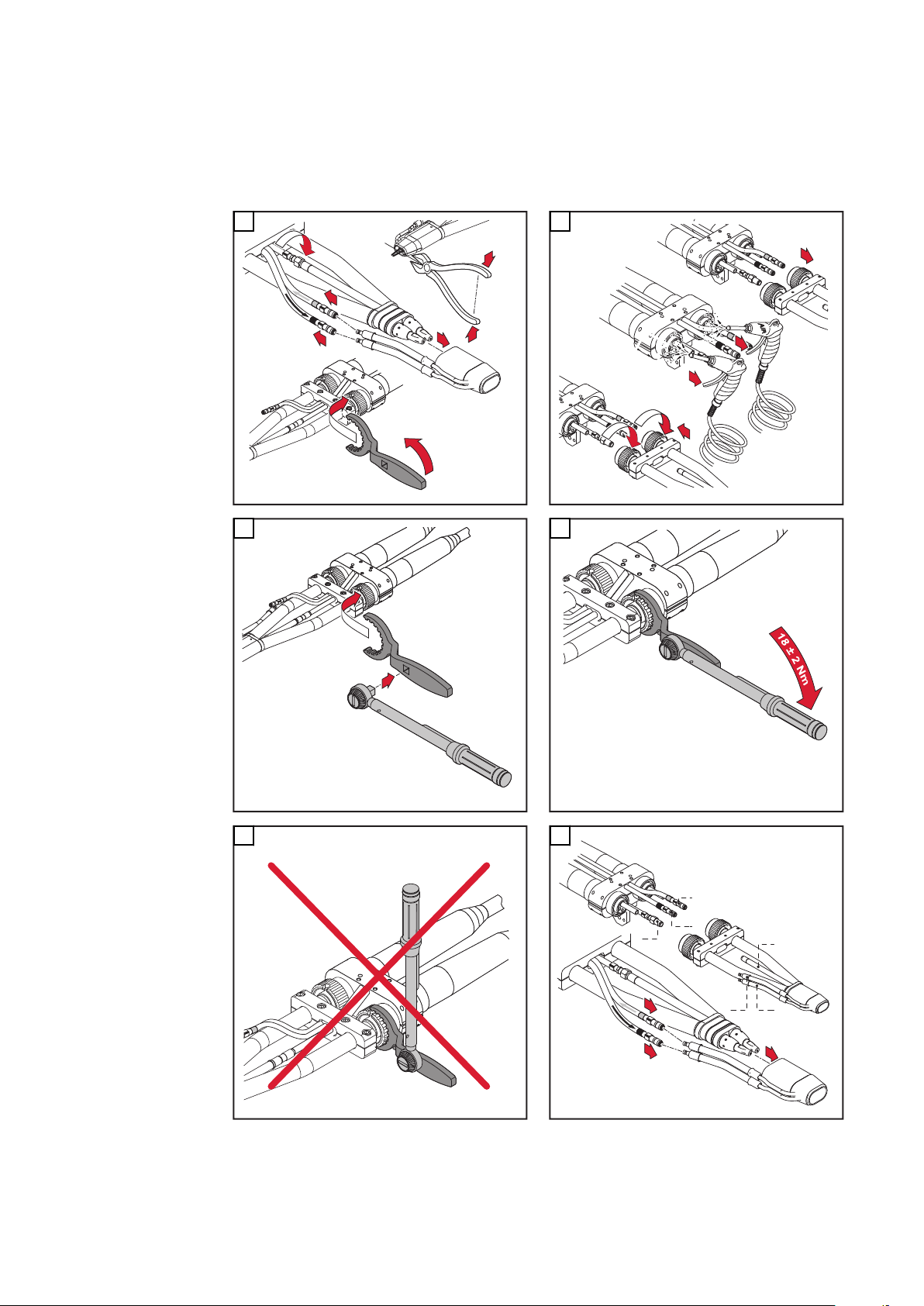
Respectez l’ordre ci-dessous lors de la connexion et de la déconnexion des con-
1
1
2
3
54
5
6
7
2
3
1
6
5
4
2
1
3
x.2x.3
x.1
x.3
x.2
x.1
1
2
3
duites :
1. Conduite de soufflage x.1
2. Arrivée d’eau x.2 (bleu)
3. Retour d’eau x.3 (rouge)
1
3 4
2
5
90
6
Page 91

Démonter et
monter un coude
Robacta Twin
Compact Pro
FR
Remplacer les
pièces d’usure
de la torche de
soudage Robacta
1
Robacta 160
3
2
Robacta 280
4
Robacta 300 / 500
Robacta 400
91
Page 92

5
6
Remplacer les
pièces d’usure
de la torche de
soudage Robacta / MTW 500-M
Robacta 700 / 700 TIME
1
Robacta 5000
Robacta 2500
2
MTW 500-M Con-Drive
92
Page 93

Remplacer les
1
2
1
2
3
4
1
2
*
8 Nm
3
4
1
pièces d’usure
de la torche de
soudage Robacta
Twin
IMPORTANT! Toujours utiliser deux tubes de contact identiques.
ATTENTION!
Toujours utiliser deux tubes de contact identiques.
Cela peut entraîner des dommages matériels graves.
Respecter impérativement l’ordre des étapes et les couples de serrage indi-
▶
qués.
* Au lieu de l’outil fourni de série, une clé cynamométrique assortie d’une
clé à douille adaptée sont proposées en option. Ainsi, il est assuré que les
éléments de construction sont associés en appliquant le couple de serra-
ge indiqué. Pour les numéros de référence, voir la liste des pièces de re-
change.
1
2
FR
3
4
93
Page 94
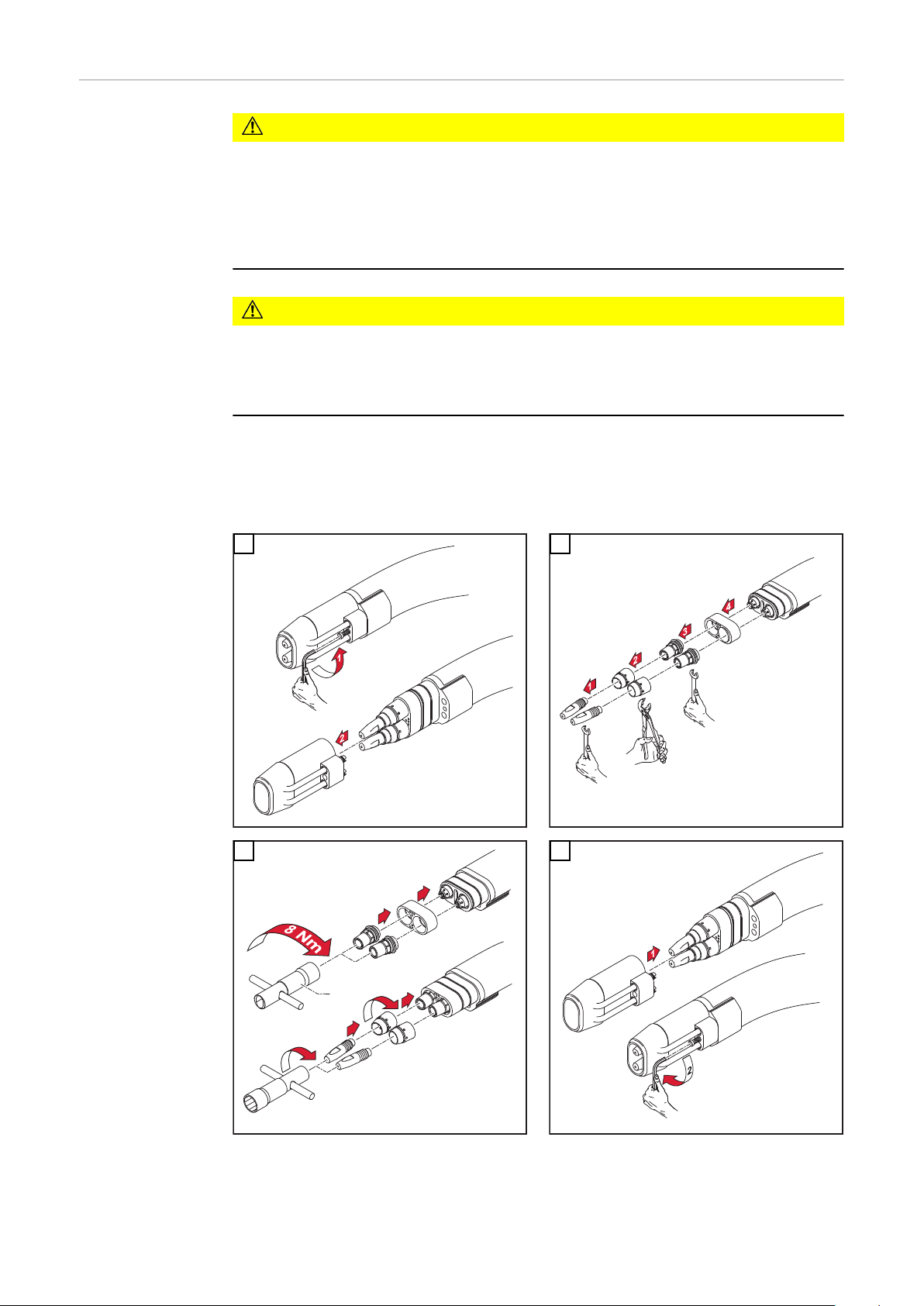
Robacta Twin
1
2
3
4
*
Compact Pro Échanger les
éléments
ATTENTION!
Risque de brûlure par chalumeau à souder fortement échauffé (refroidissement
trop chaud).
Cela peut entraîner de graves brûlures.
Le changement des composants ainsi que le nettoyage et la vérification des
▶
composants peuvent s’effectuer seulement dans l’état refroidi du chalumeau.
ATTENTION!
Danger en cas d'erreur de manipulation et d'erreur en cours d'opération.
Cela peut entraîner des dommages matériels graves.
Respecter impérativement l’ordre des étapes de travail et les moments de
▶
couple indiqués.
* A la place de l’outil systématiquement compris dans la livraison, on peut
demander en option une clé de couple ainsi que la clé tubulaire corre-
spondante. Ainsi, les éléments seront effectivement serrés au moment de
couple indiqué. Pour le numéro d’article, voir la liste de pièces détachées.
1 2
94
3 4
Page 95

Remplacer la bu-
1
2
1
*
*
1
1
2
se gaz Robacta
160 / 300 / 500
Robacta 700 /
700 Time MTW
500-M Con-Drive
ATTENTION!
Risque de dommage sur les joints toriques en cas de retrait ou de montage non
conforme de la buse gaz.
Cela peut entraîner des dommages matériels graves.
Retirer ou monter la buse gaz uniquement avec l’écrou-raccord ouvert.
▶
Lors du montage de la buse gaz, veiller à ce que les trous de la bague soient
▶
placés exactement au-dessus des trous du corps de la torche. Dans le cas
contraire, le refroidissement suffisant de la buse gaz n’est pas garanti.
* Sens de rotation indiqué !
1
3
FR
2
4
Assemblage du
guidecâble
IMPORTANT! Pour couper à la bonne longueur les structures du guide-câble, as-
surez-vous que
le guide-câble est situé à proximité du tube de contact
-
le tube de contact soit solidement attaché au coude
-
* Le système de guidage du fil 44,0350,1806 ne peut être monté et
démonté que par l’avant pour un corps de torche de Robacta 280 45°.
** Tube de contact avec trou de centrage
*** Tube de contact sans trou de centrage
95
Page 96

1
2
1
1
1
*
Robacta 280 45°
2
1
**
***
1
0 mm
.
0
inch
2
1
2
3
5
4
Assemblage du
guidecâble Twin
96
IMPORTANT! Pour couper à la bonne longueur les structures du guide-câble, assurez-vous que
le tube de contact soit solidement attaché au coude
-
der Draht-Führungseinsatz satt am Kontaktrohr anliegt
-
* Tube de contact avec trou de centrage
** Tube de contact sans trou de centrage
Page 97

IMPORTANT! Utilisez toujours deux tubes de contact du même type.
1
2
1
2
**
*
1
2
1
0
m
m
.0 in
c
h
1
2
1
2
x.2x.3
x.1
x.3
x.2
x.1
1
2
3
Lors du branchement des câbles, respectez la séquence suivante :
1. Conduite d’évacuation x.1
2. Entrée d’eau x.2 (bleu)
3. Sortie d’eau x.3 (rouge)
1
2
FR
3
4
5
6
97
Page 98

Assemblage des
2
1
1
2
1
6
7
1
2
3
5
4
pièces d’usure
sur la boîte de
commande
IMPORTANT! Respectez la procédure suivante pour placer le coude sur le point
de mise en parallèle du Robacta Drive : le guide-fil doit sortir sans pliure du point
de mise en parallèle du Robacta Drive.
ATTENTION!
Danger de fuite de fluide de refroidissement.
Cela peut entraîner des dommages matériels graves.
Lors de l’assemblage du coude, assurez-vous que les écrous d’accouplement
▶
sont fixés fermement.
IMPORTANT! La clé spéciale pour les écrous d’accouplement permet de les serrer plus facilement.
1
3
2
4
98
Page 99

1
2
5
5
3
2
1
4
3
2
1
1
1
1
2
(0 in.)
0 m
m
3
4
1
6
FR
Montage de
l’âme en plastique
ATTENTION!
Danger de pliure de la gaine guide-fil.
Cela peut entraîner des dommages matériels graves.
Le tube doit être droit avant son insertion.
▶
Arrondir l’extrémité du fil de soudage avant de l’enfiler.
▶
1
2
3
4
99
Page 100

1
2
5
3
2
1
1
1
1
(0 in.)
0 m
m
4
2
2
3
3
1
Montage de
l’âme d’acier
IMPORTANT! Respectez la procédure suivante pour le montage de l’âme d’acier :
Après avoir coupé l’intérieur en acier en longueur, enlevez la bavure restante
-
Le tube doit être droit avant d’enfiler l’âme d’acier.
-
Arrondir l’extrémité du fil de soudage avant de l’enfiler.
-
1
3
2
4
100
 Loading...