

Page 1

Robacta Drive mit Zwischentrieb
Robacta Drive with intermediate drive
Robacta Drive avec entrainement intermediaire
Einbauanleitung
D
Drahtvorschub
Installation Instructions
GB
Wirefeeder
Instructions d’installation
F
Dévidoir-fil
42,0410,0584 032003
Page 2

Page 3
Einbauanleitung für Robacta Drive mit Zwischentrieb
Allgemeines
Einbauset Robacta Drive Single
Warnung! Fehlerhaft durchgeführte Arbeiten können schwerwiegende Sach- und
Personenschäden verursachen. Nachfolgend beschriebene Tätigkeiten dürfen
nur von Fronius-geschultem Fachpersonal durchgeführt werden! Beachten Sie
die Sicherheitsvorschriften in der Bedienungsanleitung der Stromquelle.
Warnung! Ein Elektroschock kann tödlich sein. Vor Öffnen des Gerätes:
- Netzschalter der Stromquelle in Stellung „O“ schalten
- Stromquelle vom Netz trennen
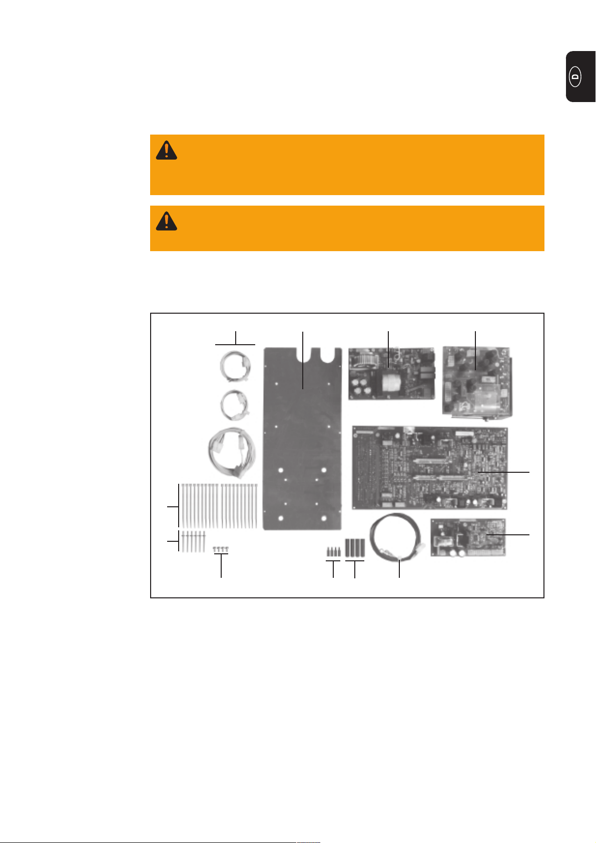
Das Einbauset 4,100,210,U besteht aus folgenden Bauteilen:
(1) (8)(7)(6)
(9)
(11)
(10) (4) (5) (6)
Abb.1 Einbauset
(1) Print NVZ 42
(2) Print PV 45 S
(3) Print NMI 4 RD
(4) 4 Distanzen M4x15
(5) 4 Distanzen M4x40
(6) Kabelbaum Robacta Drive
(7) Printaufnahmeblech
(8) Steuertrafo 220-415V/50H
(9) 20 Kabelbinder
(10)4 Linsenblechschrauben 4,8x9,5
(11)6 Nieten 3,2
(3)
(2)
1
Page 4
Umbau auf
Robacta Drive
Single
- Gehäusedeckel und Seitenteile abschrauben
- Steuertrafo, NMI 4D und BM 45B abstecken und durch neuen Steuertrafo, NMI 4RD,
NVZ 42 und PV 45S ersetzen.
Hinweis! Printaufnahmeblech muss nur getauscht werden, wenn die Seriennummer der Stromquelle kleiner als 08303000 ist.
- Verkabelung 12pol. Molex am NMI4 RD (A4/x8) und 10 pol. Molex an PV45S A25/x3
anstecken.
- Ursprünglichen Stecker für NMI4 D (A4/x8) an der freien 12 pol. Molexkupplung
anstecken.
- 6 pol. Molexstecker an NVZ 42 (A24/x2) anstecken und primärseitig richtig am
Gleichrichter +/- befestigen.
- NVZ 42 (A24/x1) 4 pol. Molex und PV45S (A25/x1) 6 pol. Molex anstecken.
- Bestehende Leitungen vom 37 pol. CPC Geräterückseite X9/26, 27 entfernen und
durch neue Verkabelung 4 pol. Molex (A25/x2) mit X9/26,27 verbinden.
- Motor Istwertleitung von 37 pol. CPC Geräterückseite X9/29 auf X9/36 umstecken.
- Kontrolle, ob alle Verbindungen, wie im Schaltplan vorgegeben, korrekt angesteckt
sind.
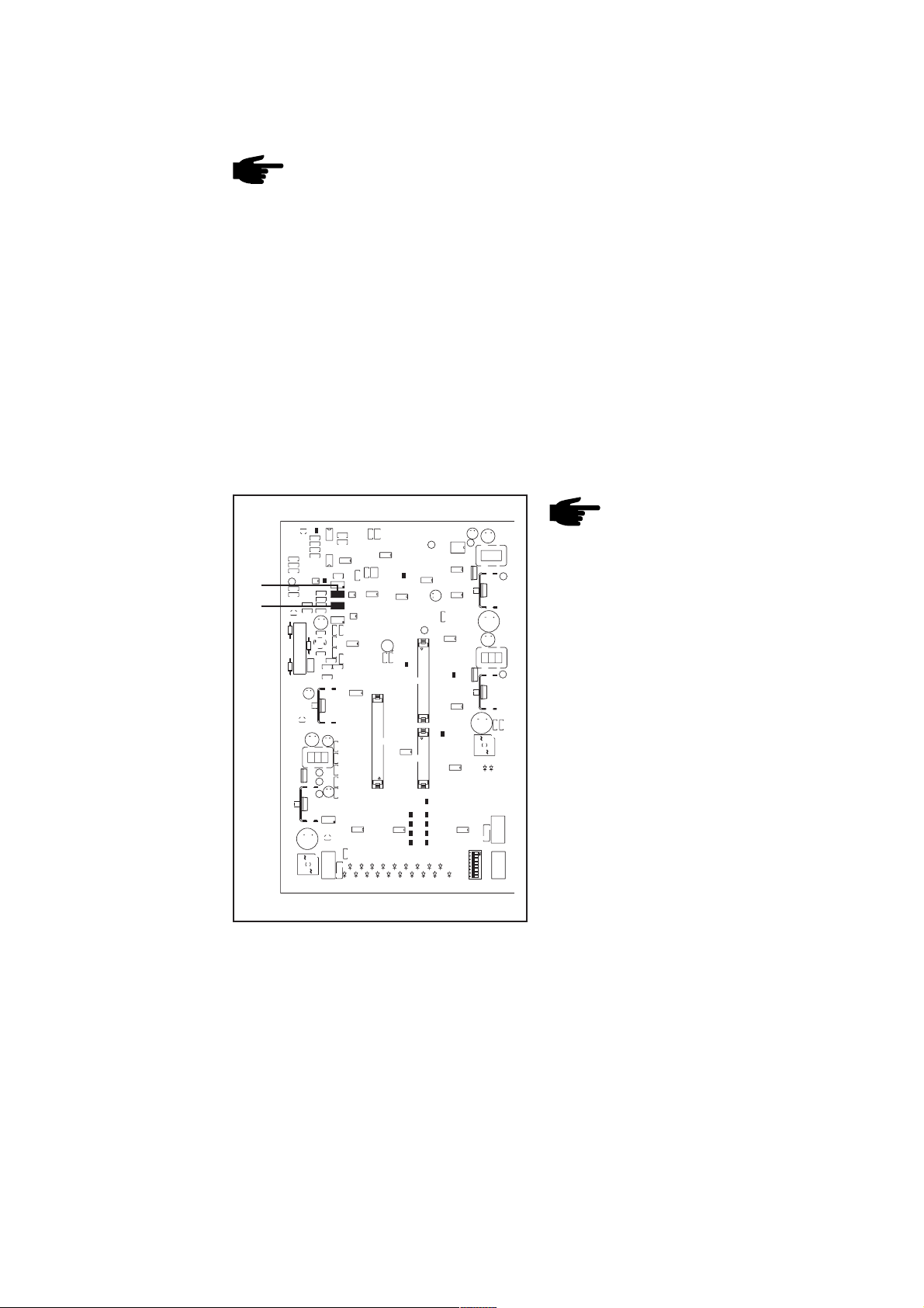
Kontrolle der
Motordrehzahl
Robacta Drive
P4
P3
Abb.2 Einstellregler Motordrehzahl am NMI 4RD
Hinweis! Drehzahlkontrolle ist nur
bei Austausch des NMI 4RD
vorzunehmen. Abgleich ist nicht
über das Setup-Menü möglich!
- Komplettes System zusammenkoppeln
(ohne Schweißdraht!)
- Kontrolle der Drehrichtung
- Drahtgeschwindigkeit auf min. 1m/min
... Drehzahl RD: 14U/min
- Korrekturmöglichkeit mit P4 am Print
NMI 4RD
- Drahtgeschwindigkeit auf max. 22m/
min ... Drehzahl RD: 310 U/min
- Korrekturmöglichkeit mit P3 am Print
NMI 4RD
- Nach erfolgter Einstellung nochmals
Minimum und Maximum-Wert kontrollieren.
2
Page 5
Einbauset Zwischentrieb Robacta Drive
Das Einbauset 4,100,211,U besteht aus folgenden Bauteilen:
(1) Print PZ 45RO
(2) 4 Distanzen steckbar
(3) Kabelbaum Zwischenantrieb
(3)
(2)
(1)
Abb.3 Einbauset
Umbau auf
Zwischenantrieb
für Robacta
Motordrehzahl
für Zwischentrieb
(VR 153/155)
nachjustieren
(7) (5) (6) (8)
Abb.4 Einbaupostition Print PZ45 RO
- Gehäusedeckel und Seitenteile abschrauben
- Snap-in-Distanzen - Abb.3/Pos.(2) - auf
die Distanzen M4x40 - Abb.4/Pos.(5) schrauben.
- Verkabelung - Abb.3/Pos.(3) - in 14 pol.
Buchse am Print PV45S (A25x4) Abb.4/Pos.(6) - stecken.
- Print PZ45 RO - Abb.3/Pos.(1) - parallel zum Print PV45 S befestigen Abb.4/Pos.(7)
- 14 pol. Stecker am Print PZ45 RO
(A26X4) anstecken - Abb.4/Pos.(8)
- 4 pol. Stecker am Print PZ45 RO
(A26X2) und 10 pol. Kupplung am 10
pol. Stecker anstecken.
- Komplettes System zusammenkoppeln
(ohne Schweißdraht!)
Vorsicht! Verletzungsgefahr
durch austretenden Schweißdraht. Schweißbrenner von
Gesicht und Körper weghalten.
Abb.5 Print PZ45RO
- Kontrolle der Drehrichtung
- Drahtgeschwindigkeit auf min. 1m/min
... Drehzahl Zwischentrieb: 10 U/min
- Korrekturmöglichkeit mit P2 am Print
PZ 45RO - Abb.5
- Drahtgeschwindigkeit auf max. 22m/
min ... Drehzahl Zwischentrieb: 226 U/
min
P1
- Korrekturmöglichkeit mit P1 am Print
PZ 45RO - Abb.5
- Nach erfolgter Einstellung nochmals
P2
Minimum und Maximum-Wert kontrollieren.
3
Page 6
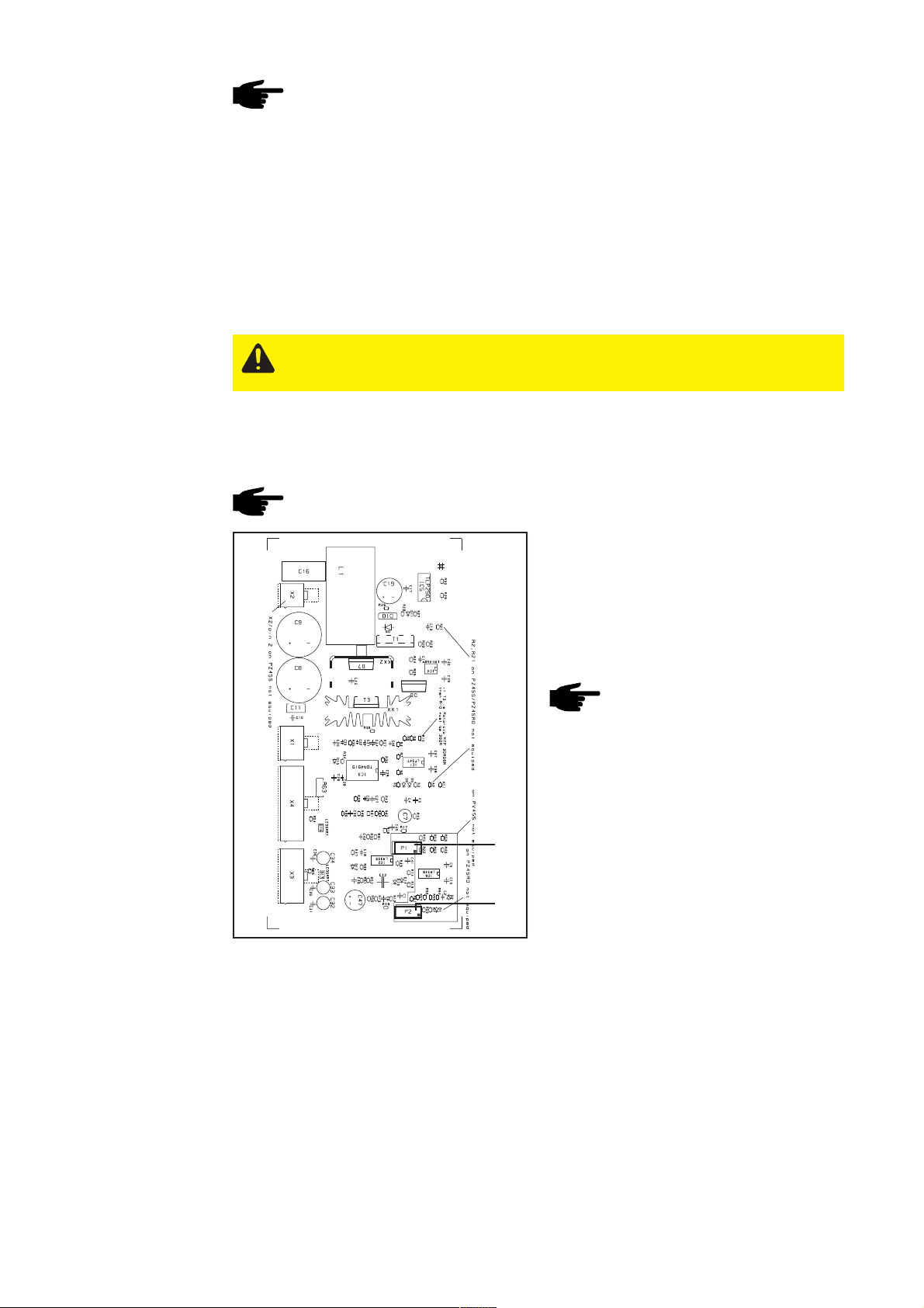
Drehzahlabgleich
für Hot-wire
Applikationen
Hinweis! Den Abgleich nur bei komplett ausgerüstetem System durchführen
(Drahtvorschub und Robacta Drive am Roboter aufgebaut). Bei als FMP-Bestellung ausgelieferten Anlagen, muss der Drehzahl-Abgleich aufgrund der Bedingungen vor Ort wiederholt werden.
Wichtig! Bei Hot-Wire Anwendungen muss die Drahtgeschwindigkeit exakt auf den
Bereich von 1 bis 5 m/min abgestimmt sein. Bei Standardanwendungen ist der Bereich
von 1 bis 22 m/min zu berücksichtigen (siehe vorangegangenes Kapitel „Kontrolle der
Motordrehzahl RobactaDrive“).
Für den Drehzahlabgleich auf eine Drahtgeschwindigkeit von 1 bis 5 m/min gehen Sie wie
folgt vor:
- Komplettes System zusammenkoppeln (mit Schweißdraht!)
Vorsicht! Verletzungsgefahr durch austretenden Schweißdraht. Schweißbrenner
von Gesicht und Körper weghalten.
- Kontrolle der Drehrichtung
- Drahtgeschwindigkeit von 1m/min vorgeben (Sollwert vom Roboter)
- Die nach einer Minute geförderte Drahtlänge abmessen (muss 1 m betragen).
Hinweis! Die Drehzahl von Robacta Drive ist Istwert-geregelt und muss daher
auch dem eingestellten Wert entsprechen.
Abb.6 Print PZ45RO
P1
P2
Korrekturmöglichkeit mit P2 am Print
PZ45RZO:
- Drahtgeschwindigkeit von 5 m/min
vorgeben (Sollwert vom Roboter)
- Die nach 30 Sekunden geförderte
Drahlänge abmessen (muss 2,5 m
betragen)
Hinweis! Die Drehzahl von
Robacta Drive ist Istwert-geregelt
und muss daher auch dem eingestellten Wert entsprechen.
Korrekturmöglichkeit mit P1 am Print
PZ45RZO:
- Drahtgeschwindigkeit von 1m/min
vorgeben (Sollwert vom Roboter)
- Die nach einer Minute geförderte
Drahtlänge abmessen (muss 1 m
betragen).
- Nach erfolgter Einstellung nochmals
Minimum und Maximum-Wert kontrollieren
4
Page 7
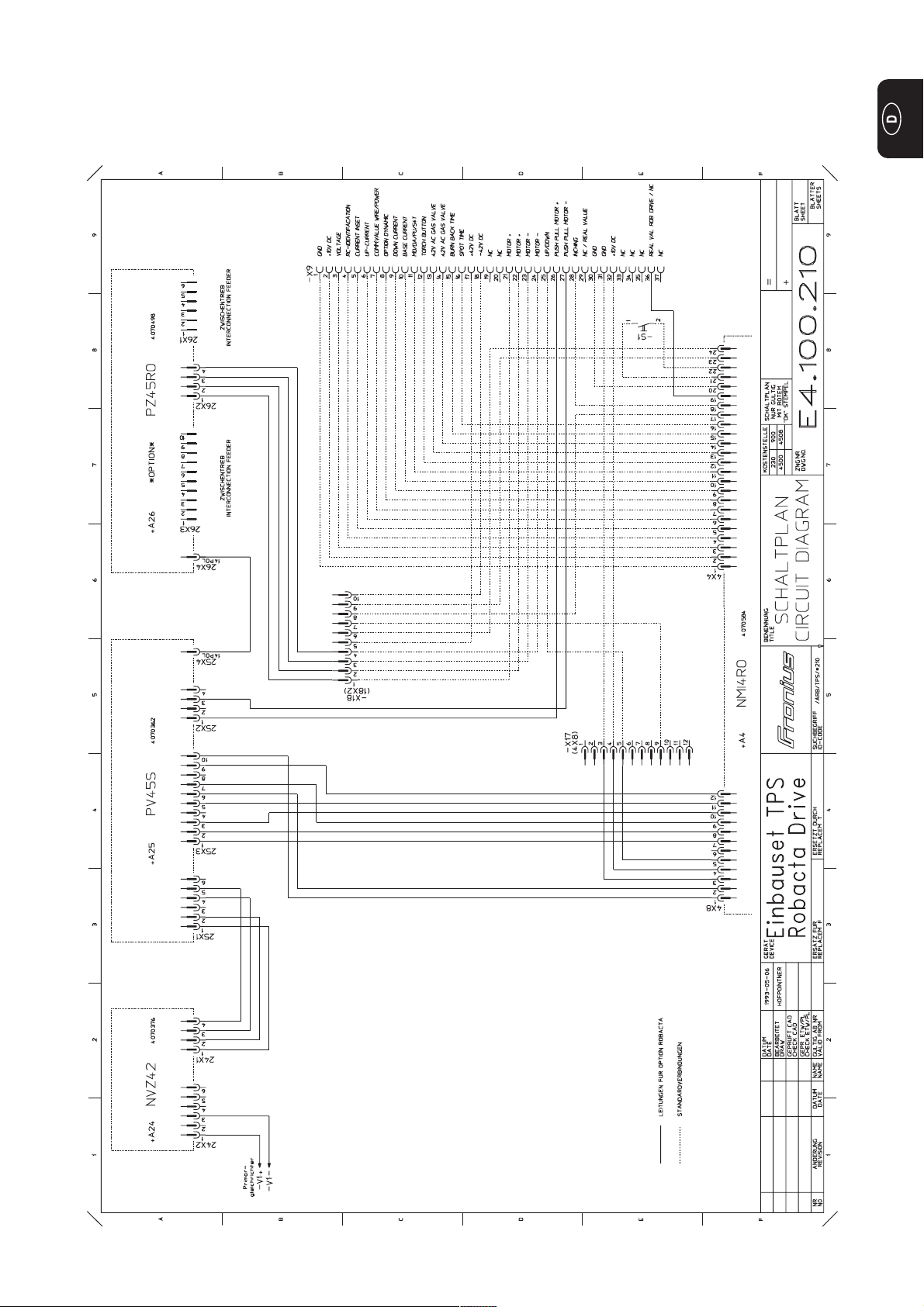
Schaltplan „Einbauset TPS Robacta Drive“
5
Page 8

6
Page 9

Conversion kit for Robacta Drive with intermediate
drive
General
Robacta Drive
Single
conversion kit
Warning! Work that is carried out incorrectly can cause serious personal injury
and damage to property. The activities described below must only be carried
out by specialist personnel trained by Fronius! Please follow the safety
regulations given in the operating instructions for the power source.
Warning! An electric shock can be fatal. Before opening the machine:
- Switch the mains switch for the power source into the “O” position
- Unplug the power source from the mains
The 4,100,210,U kit is made up of the following components:
(1) (8)(7)(6)
(9)
(11)
(10) (4) (5) (6)
Fig.1 Conversion kit
(1) P.-c. board NVZ 42
(2) P.-c. board PV 45 S
(3) P.-c. board NMI 4 RD
(4) 4 spacers M4x15
(5) 4 spacers M4x40
(6) Robacta Drive cable harness
(7) P.-c. board mounting plate
(8) Control transformer 220-415V/50H
(9) 20 cable ties
(10) 4 pan-head tapping screws 4.8x9.5
(11) 6 rivets 3.2
(3)
(2)
1
Page 10

Converting the
appliance to
“Robacta Drive
Single”
- Unscrew housing cover and cheeks
- Unplug control transformer, NMI 4D and BM 45B and replace with new control
transformer, NMI 4RD, NVZ 42 and PV 45S.
Note! Replace pc board mounting plate only in cases where the serial number
of the power source is below 08303000.
- Plug the 12-pin Molex cables into NMI4 RD (A4/x8) and the 10-pin Molex cables into
PV45S A25/x3.
- Plug the original connector for NMI4 D (A4/x8) into the vacant 12-pin Molex coupling.
- Plug the 6-pin Molex connector into NVZ 42 (A24/x2) and fasten it correctly at
primary rectifier +/-.
- Plug the 4-pin Molex connector into NVZ 42 (A24/x1) and the 6-pin Molex connector
into PV45S (A25/x1).
- Remove the existing cables from the 37-pin CPC X9/26, 27 at rear and plug into X9/
26,27, using the new 4-pin Molex cable (A25/x2).
- Unplug the actual-motor-value lead from the 37-pole CPC X9/29 at rear, and plug it
into X9/36.
- Check all connections to make sure they are in accordance with the wiring diagram.
Checking the
motor speed on
the Robacta
Drive
P4
P3
Fig.2 Motor speed adjustment knob on NMI 4RD
Note! Speed check required only
in case of NMI 4RD replacement.
No alignment is possible in the
set-up menu!
- Assemble entire system (without
welding wire!)
- Check sense of rotation
- Set wirefeed speed to a minimum of
1m/min ... speed RD: 14 rpm
- Correction possible with P4 on pc
board NMI 4RD
- Set wire feed speed to a maximum of
22m/min ... speed RD: 310 rpm
- Correction possible with P3 on pc
board NMI 4RD
- Following alignment, check the
minimum and maximum value once
again.
2
Page 11

“Intermediate
Drive for Robacta
Drive”
conversion kit
The 4,100,211,U kit is made up of the following components:
(1) P.-c. board PZ 45RO
(2) 4 spacers, plug-in type
(3) Cable harness for intermediate drive
(3)
(2)
(1)
Fig.3 Conversion kit
Converting
appliance to
“Intermediate
Drive for
Robacta”
Motor speed
readjustment for
Intermediate
Drive (VR 153/
155)
(7) (5) (6) (8)
Fig.4 Installation location of pc board PZ45 RO
- Unscrew housing cover and side
panels
- Screw snap-in spacers - Fig.3/Item (2)
- onto spacers M4x40 - Fig.4/Item (5).
- Plug cables - Fig.3/Item (3) - into the
14-pin jack on pc board PV45S
(A25x4) - Fig.4/Item (6).
- Fit pc board PZ45 RO - Fig.3/Item (1) parallel to pc board PV45 S - Fig.4/
Item (7)
- Plug the 14-pin connector into pc
board PZ45 RO (A26X4) - Fig.4/Item
(8)
- Plug the 4-pin connector onto pc board
PZ45 RO (A26X2) and the 10-pin
coupling into the 10-pin jack.
- Assemble entire system (without
welding wire!)
Caution! Risk of injury from
welding wire emerging at speed
from the torch. Hold the torch so
that it points away from your face
and body.
Fig.5 Pc board PZ45RO
- Check sense of rotation
- Set wirefeed speed to the minimum of
1m/min ... intermediate drive speed:
10 rpm
- Correction possible with P2 on pc
board PZ 45RO - Fig.5
P1
- Set wirefeed speed to the maximum of
22m/min ... intermediate drive speed:
226 rpm
- Correction possible with P1 on pc
P2
board PZ 45RO - Fig.5
- Following alignment, check the
minimum and maximum value once
again.
3
Page 12

Speed alignment
for hot-wire
applications
Note! Only carry out the alignment on a completely tooled-up system (the
wirefeeder and Robacta Drive must have been mounted at the robot). Where an
installation is supplied under an “FMP” order (the German initials stand for
“ready mounted and test-welded”), the speed alignment must be repeated insitu, due to the different conditions encountered here.
Important! With hot-wire applications, the wirespeed must be exactly fine-tuned to the
1 to 5 m/min range. With standard applications, the 1 to 22 m/min range should be used
(see previous section: “Checking the motor speed on the Robacta Drive”).
To carry out a speed alignment to a wirespeed of 1 to 5 m/min, proceed as follows:
- Couple the whole system together (complete with welding wire!)
Caution! Risk of injury from welding wire emerging at speed from the torch.
Hold the torch so that it points away from your face and body.
- Check the direction of rotation
- Specify a wirespeed of 1m/min (command value from robot)
- Measure the length of wire that has been fed after 1 minute (must be 1 m).
Note! The speed of the Robacta Drive is controlled with reference to actual
values and so must also correspond with the pre-set value.
Correction possible with P2 on p.-c. board
PZ45RZO:
- Specify a wirespeed of 5m/min
(command value from robot)
- Measure the length of wire that has
been fed after 30 seconds (must be
2.5 m)
Fig.6 P.-c. board PZ45RO
P1
P2
Note! The speed of the Robacta
Drive is controlled with reference
to actual values and so must also
correspond with the pre-set value.
Correction possible with P1 on p.-c. board
PZ45RZO:
- Specify a wirespeed of 1m/min
(command value from robot)
- Measure the length of wire that has
been fed after 1 minute (must be 1 m).
- Following alignment, check the
minimum and maximum values once
again
4
Page 13

Wiring diagram for TPS Robacta Drive conversion kit
5
Page 14

6
Page 15

Set de modification robacta drive single
Généralités
Einbauset Robacta Drive Single
Avertissement! Les travaux mal faits peuvent entrainer de garves dommages
corporels et matériels. Les opéracions décrites ci-après ne doivent être effectuées que par des membres du personnel formés par Fronius ! Observez les
consignes de sécurité du mode d’emploi de la source de courant.
Avertissement! Un électochoc peut être mortel. Avant d’ouvrir l’appareil:
- Commuter l’interrupteur principal de la source de courant enposition „O“
- Débrancher la prise de la source de courant
Le kit 4,100,210,U est composé des éléments suivants:
(1) (8)(7)(6)
(9)
(11)
(10) (4) (5) (6)
Fig.1 Set de modification Robacta Drive Single
(1) Plaquette NVZ 42
(2) Plaquette PV 45 S
(3) Plaquette NMI 4 RD
(4) 4 Entretoise M4x15
(5) 4 Entretoise M4x40
(6) Harnais des câbles Robacta Drive
(7) Plaque de montage pour la plaquette
(8) Transfo de commande 220-415V/50H
(9) 20 cravates de câbles
(10) 4 vis à tête goutte-de-suif 4,8x9,5
(11) 6 rivets 3,2
(3)
(2)
1
Page 16

Transformation
en Robacta Drive
Single
- Dévisser couvercle du boîtier et joues latérales.
- Oter transfo de commande, NMI 4D et BM 45B et remplacer par nouveau transfo de
commande, NMI 4RD, NVZ 42 et PV 45S.
Nota! Ne remplacer la plaque de montage pour la plaquette que si la source de
courant a un numéro de série inférieur à 08303000.
- Ficher câbles Molex à 12 fiches sur la NMI4 RD (A4/x8) et Molex à 10 fiches dans
PV45S A25/x3.
- Ficher connecteur original pour la NMI4 D (A4/x8) dans le prolongateur Molex à 12
fiches libre.
- Ficher connecteur Molex à 6 fiches dans NVZ 42 (A24/x2) et raccorder correctement
au redresseur primaire +/-.
- Ficher connecteur Molex à 4 fiches dans NVZ 42 (A24/x1) et Molex à 6 fiches dans
(A25/x1.
- Retirer lignes existantes du CPC à 37 fiches sur le dos de l‘appareil et relier avec
X9/26,27 par nouveau câble Molex à 4 fiches (A25/x2).
- Retirer ligne de valeur effective de moteur du CPC à 37 fiches X9/29 sur le dos de
l‘appareil et ficher dans X9/36.
- Vérifier si tous les raccords sont conformes au schéma de connexions.
Contrôle du
nombre des tours
du moteur au
Robacta Drive
P4
P3
Fig.2 Bouton de réglage sur la NMI 4RD pour le
nombre des tours du moteur
Nota! Le contrôle du nombre des
tours n‘est possible que si la NMI
4RD est remplacé. Le réglage
dans le menu Setup n‘est pas
possible!
- Assembler système entier (sans fil de
soudage!)
- Contrôler sens de rotation
- Régler vitesse du dévidoir-fil à 1m/min
au minimum ... nombre des tours RD:
14 tr/min
- Modification possible au P4 sur la
plaquette NMI 4RD
- Régler vitesse du dévidoir-fil à 22m/
min au maximum... nombre des tours
RD: 310 tr/min
- Modification possible au P3 sur la
plaquette NMI 4RD
- Une fois le réglage terminé, contrôler
de nouveau la valeur minimale et
maximale.
2
Page 17

Set de modification „Entraînement
Intermédiaire
Robacta Drive“
Le kit 4,100,211,U est composé des éléments suivants:
(1) Plaquette PZ 45RO
(2) 4 Entretoises encliquetables
(3) harnais de câbles pour entraînement
(3)
intermedaire
(2)
(1)
Abb.3 Einbauset
Transformation
en entraînement
intermédiaire
pour Robacta
Réajuster le
nombre des tours
du moteur pour
l‘entraînement
intermédiaire (VR
153/155)
(7) (5) (6) (8)
Abb.4 Einbaupostition Print PZ45 RO
- Dévisser couvercle du boîtier et joues
latérales
- Visser entretoises encliquetables fig.3/pos.(2) - sur les entretoises
M4x40 - fig.4/pos.(5).
- Ficher câbles - fig.3/pos.(3) - dans
douilles à 14 fiches sur la plaquette
PV45S (A25x4) - fig.4/pos.(6).
- Installer plaquette PZ45 RO - fig.3/
pos.(1) - parallèlement à la plaquette
PV45 S - fig.4/pos.(7)
- Ficher connecteur à 14 fiches sur la
plaquette PZ45 RO (A26X4) - fig.4/
pos.(8)
- Ficher connecteur à 4 fiches sur la
plaquette PZ45 RO (A26X2) et prolongateur à 10 fiches dans connecteur à
10 fiches.
- Assembler système entier (sans fil de
soudage!)
Attention ! Risque de blessure
avec le fil de soudage sortant.
Tenir la torche éloignée du
visage et du corps.
Fig.5 Plaquette PZ45RO
- Contrôler sens de rotation
- Régler vitesse du dévidoir-fil à 1m/min
au minimum ... nombre des tours RD:
10 tr/min
- Modification possible au P2 sur la
plaquette PZ 45RO - fig.5
- Régler vitesse du dévidoir-fil à 22m/
min au maximum... nombre des tours
P1
RD: 226 tr/min
- Modification possible au P1 sur la
plaquette PZ 45RO - fig.5
P2
- Une fois le réglage terminé, contrôler
de nouveau la valeur minimale et
maximale.
3
Page 18

Ajustage du
nombre de tours
pour applications
fil chaud
Nota! Effectuer l‘ajustage uniquement sur un système entièrement équipé
(dévidoir-fil et Robacta Drive montés sur le robot). Sur les installations commandées en livraison “monté et testé“, l‘ajustage du nombre de tours doit être
réitérée sur site.
Important ! Pour les applications fil chaud, la vitesse d‘avance du fil doit être réglée
exactement sur une plage de 1 à 5 m/min. Pour les applications standard, la plage est
de 1 à 22 m/min (voir chapitre précédent “Contrôle du nombre de tours du moteur au
Robacta Drive“).
Pour ajuster le nombre de tours sur une vitesse d‘avance du fil de 1 à 5 m/min, procédez de la manière suivante :
- assemblez le système complet (avec fil de soudage !)
Attention ! Risque de blessure avec le fil de soudage sortant. Tenir la torche
éloignée du visage et du corps.
- contrôlez le sens de rotation
- programmez une vitesse d‘avance du fil de 1m/min (valeur de consigne du robot)
- mesurez au bout d‘une minute la longueur de fil transporté (doit faire 1 m).
Nota ! Le nombre de tours du Robacta Drive est réglé sur la valeur réelle et doit
par conséquent correspondre à la valeur de réglage.
Fig.6 Print PZ45RO
P1
P2
Possibilité de correction avec P2 sur la
plaquette PZ45RZO :
- régler la vitesse d‘avance du fil sur 5
m/min (valeur de consigne du robot)
- mesurer la longueur de fil transporté
après 30 secondes (doit faire 2,5 m)
Nota ! Le nombre de tours du
Robacta Drive est réglé sur la
valeur réelle et doit par conséquent correspondre à la valeur de
réglage.
Possibilité de correction avec P1 sur la
plaquette PZ45RZO :
- régler la vitesse d‘avance du fil sur 1
m/min (valeur de consigne du robot)
- mesurer au bout d‘une minute la
longueur de fil transporté (doit faire 1
m)
- Lorsque le réglage est terminé, contrôler une nouvelle fois les valeurs
minimale et maximale.
4
Page 19

Schéma de connexions „Set de modification TPS
Robacta Drive“
5
Page 20

6
Page 21

FRONIUS INTERNATIONAL GMBH
Buxbaumstraße 2, A-4600 Wels, Austria
Tel: +43 (0)7242 241-0, Fax: +43 (0)7242 241-3940
E-Mail: sales@fronius.com
www.fronius.com
Under http://www.fronius.com/addresses you will find all addresses
www.fronius.com/addresses
of our Sales & service partners and Locations.
ud_fr_st_so_00082 012008
 Loading...