


Operating
instructions
Robacta Drive CMT W
Robacta Drive CMT W Pro
Robacta Drive CMT PAP W
Robacta Drive CMT PAP W Pro
RA Drive CMT PAP W FL
Bedienungsanleitung
DE
Operating instructions
EN
Návod k obsluze
CS
Návod na obsluhu
SK
ZH
操作说明书
42,0410,1384 016-30052022


Inhaltsverzeichnis
Sicherheit 4
Sicherheit 4
Installation und Inbetriebnahme 6
Gerätekonzept 6
Erstausrüstung und Werkzeug 6
Grundausstattung Robacta Drive CMT Pro 7
Rohrbogen-Empfehlung 8
Draht-Führungseinsatz montieren 9
Verschleißteile an der Antriebseinheit montieren 10
Schlauchpaket montieren und anschließen 12
PAP Schlauchpaket montieren und anschließen 13
Drahtpuffer anschließen 14
RA Drive CMT-PAP W FL anschließen 15
Schweißbrenner anschließen 18
Externen Draht-Förderschlauch anschließen 18
Richtige Verlegung des Roboter-Schlauchpaketes 19
Maximale Achsrotation PAP 20
Bedienelemente und Funktionen 21
Anpressdruck einstellen 22
Haltewinkel wechseln 23
Verschleißteile am Rohrbogen wechseln 23
Robacta Drive CMT Pro Gasdüsen-Positionsset wechseln 24
Pflege, Wartung und Entsorgung 26
Allgemeines 26
Bei jeder Inbetriebnahme 27
Bei jedem Austausch der Draht-Spule 28
Entsorgung 28
Gewährleistung 29
Fehlerdiagnose, Fehlerbehebung 30
Fehlerdiagnose, Fehlerbehebung 30
Technische Daten 35
CMT 35
DE
3

Sicherheit
Sicherheit
WARNUNG!
Gefahr durch Fehlbedienung und fehlerhaft durchgeführte Arbeiten.
Schwere Personen- und Sachschäden können die Folge sein.
Alle in diesem Dokument beschriebenen Arbeiten und Funktionen dürfen
▶
nur von technisch geschultem Fachpersonal ausgeführt werden.
Dieses Dokument vollständig lesen und verstehen.
▶
Sämtliche Sicherheitsvorschriften und Benutzerdokumentationen dieses
▶
Gerätes und aller Systemkomponenten lesen und verstehen.
WARNUNG!
Gefahr durch elektrischen Strom.
Schwere Personen- und Sachschäden können die Folge sein.
Vor Beginn der Arbeiten alle beteiligten Geräte und Komponenten ausschal-
▶
ten und von Stromnetz trennen.
Alle beteiligten Geräte und Komponenten gegen Wiedereinschalten sichern.
▶
WARNUNG!
Gefahr durch elektrischen Strom infolge von schadhaften Systemkomponenten
und Fehlbedienung.
Schwere Personen- und Sachschäden können die Folge sein.
Sämtliche Kabel, Leitungen und Schlauchpakete müssen immer fest ange-
▶
schlossen, unbeschädigt, und korrekt isoliert sein.
Nur ausreichend dimensionierte Kabel, Leitungen und Schlauchpakete ver-
▶
wenden.
WARNUNG!
Rutschgefahr durch Kühlmittel-Austritt.
Schwere Personen- und Sachschäden können die Folge sein.
Die Kühlmittel-Schläuche der wassergekühlten Schweißbrenner immer mit
▶
dem darauf montierten Kunststoff-Verschluss verschließen, wenn diese vom
Kühlgerät oder anderen Systemkomponenten getrennt werden.
WARNUNG!
Gefahr durch heiße Systemkomponenten und / oder Betriebsmittel.
Schwere Verbrennungen und Verbrühungen können die Folge sein.
Vor Beginn der Arbeiten alle heißen Systemkomponenten und / oder Be-
▶
triebsmittel auf +25 °C / +77 °F abkühlen lassen (beispielsweise Kühlmittel,
wassergekühlte Systemkomponenten, Antriebsmotor des Drahtvorschubes, ...).
Geeignete Schutzausrüstung tragen (beispielsweise hitzebeständige Schutz-
▶
handschuhe, Schutzbrille, ...), wenn ein Abkühlen nicht möglich ist.
4

WARNUNG!
Gefahr durch Kontakt mit giftigem Schweißrauch.
Schwere Personenschäden können die Folge sein.
Schweißrauch immer absaugen.
▶
Für ausreichend Frischluft-Zufuhr sorgen. Sicherstellen, dass eine
▶
Durchlüftungsrate von mindestens 20 m³ (169070.1 US gi) pro Stunde zu jeder Zeit gegeben ist.
Im Zweifelsfall die Schadstoffbelastung am Arbeitsplatz durch einen Sicher-
▶
heitstechniker feststellen lassen.
VORSICHT!
Gefahr durch Betrieb ohne Kühlmittel.
Sachschäden können die Folge sein.
Wassergekühlte Geräte nie ohne Kühlmittel in Betrieb nehmen.
▶
Während des Schweißens sicherstellen, dass ein ordnungsgemäßer Kühlmit-
▶
tel-Durchfluss gegeben ist - bei Verwendung von Fronius-Kühlgeräten ist
dies der Fall, wenn im Kühlmittel-Behälter des Kühlgerätes ein ordnungsgemäßer Kühlmittel-Rückfluss ersichtlich ist.
Für Schäden aufgrund von Nichtbeachtung der oben angeführten Punkte
▶
haftet der Hersteller nicht, sämtliche Gewährleistungsansprüche erlöschen.
VORSICHT!
DE
Verbrennungsgefahr durch heiße Oberfläche.
Schwere Personenschäden können die Folge sein.
Die Oberflächentemperatur der Robacta Drive CMT kann bei einer max. Um-
▶
gebungstemperatur von 40°C im Betrieb einen Wert von bis zu 90°C erreichen. Diese Temperatur ist eine übliche Betriebstemperatur und stellt keine
Gefährdung für die Robacta Drive CMT dar.
5

Installation und Inbetriebnahme
1x
1x
1x
0,9 1,0
.035 .047
mm
inch
1x 1x 1x
3x
1x
"CB" "CB"
Al
1,2 1,6
.039 .063
a)
)b)b
3x
1x
1x
1x
1x
0,8 0,9
.032 .039
mm
inch
1x 1x 1x
3x
1x
"CB" "CB"
1,0 1,2
.035 .047
c)
)d)d
3x
1x
Steel
CuSi
Gerätekonzept Der CMT Roboter-Schweißbrenner Robacta Drive CMT besteht aus Rohrbogen,
Antriebseinheit mit Haltewinkel und Schlauchpaket.
In Kombination mit dem Drahtpuffer am Schlauchpaket sorgt der integrierte
Draht-Antriebsmotor für eine schnelle, reversierende Bewegung der Drahtelektrode. Die externe Drahtführung ermöglicht einen raschen Wechsel aller DrahtFörderkomponenten. Vielfältige Rohrbogen-Ausführungen ermöglichen eine gute Zugänglichkeit zur Schweißstelle.
Robacta Drive CMT eignet sich besonders für:
Dünnblech-Anwendungen allgemein
-
Spritzerfreies MIG-Löten von verzinkten Dünnblechen
-
Fügen von Stahl mit Aluminium.
-
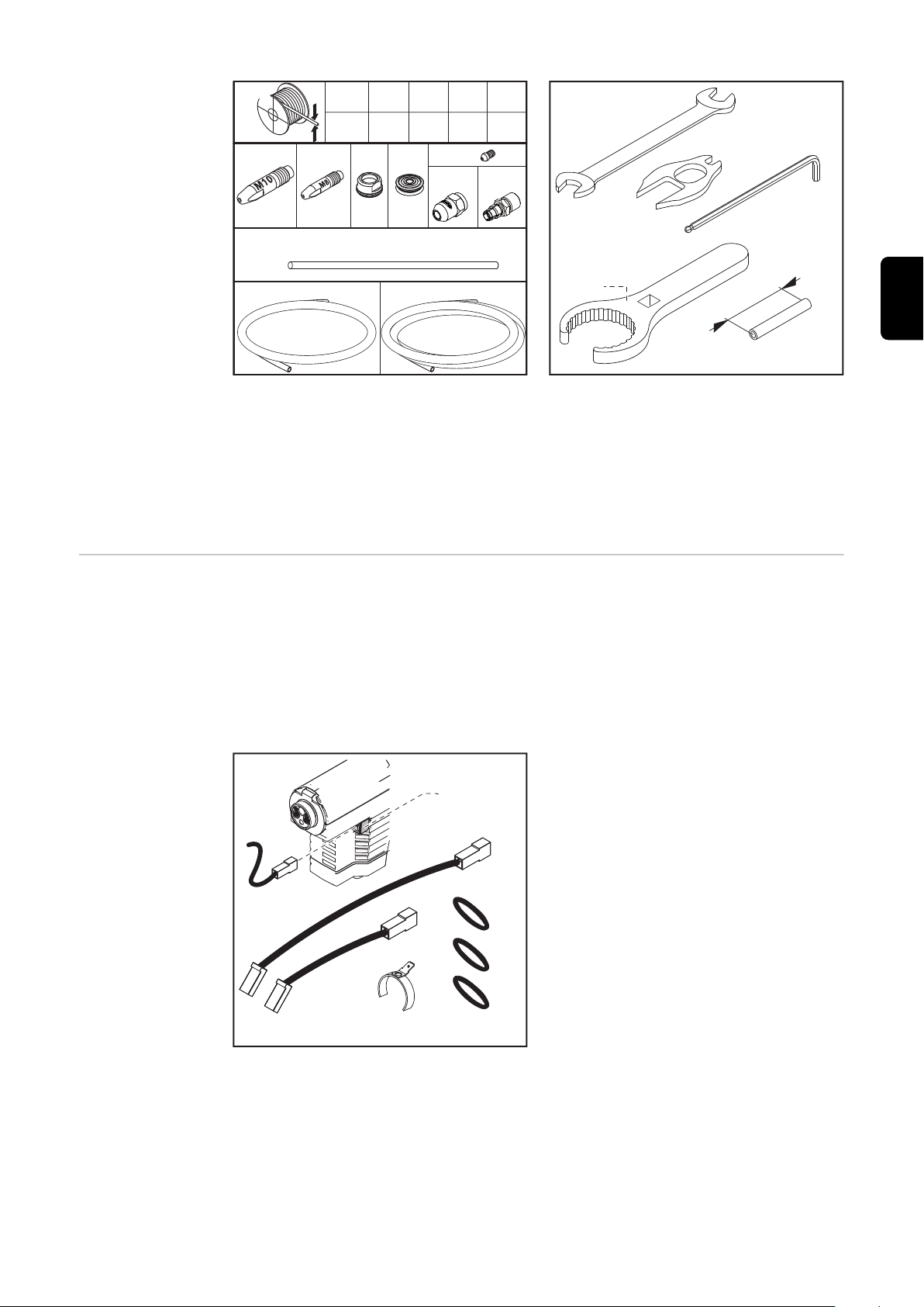
Erstausrüstung
und Werkzeug
Für den Betrieb des Robacta Drive CMT ist eine dem Drahtdurchmesser und dem
Zusatz-Werkstoff entsprechende Erstausrüstung erforderlich (siehe Ersatzteilliste):
Erstausrüstung Alu
-
Erstausrüstung Stahl / CuSi
-
Erstausrüstung CrNi
-
a) Graphit mit Endstück
b) Graphit
c) Bronze
d) Stahl
6

1x
1x1x
0,8 0,9
.032 .039
mm
inch
1x 1x 1x
3x
1x
"CB" "CB"
1,0 1,2
.035 .047
c)
)b)b
3x
1x
CrNi
*
(1.60 in
.)
4
0
mm
2x
Werkzeug:
**
*
Gabelschlüssel SW 10/12
-
Arretierschlüssel SW 13
-
Ablängrohr (zum Ablängen des Draht-Führungseinsatzes)
-
Innensechskant-Schlüssel SW 3
-
* „Schlüssel für Überwurfmutter“ (Option)
DE
Grundausstattung Robacta
Drive CMT Pro
* Flachstecker am Gehäuse
** Gasdüsen-Positionsset
inkl.
- Sensorkabel 290 mm
- Sensorkabel 430 mm
(je nach Rohrbogen-Länge und -Krümmung)
7

RohrbogenEmpfehlung
(1)
(2)
(3)
(4)
(5)
(6)
Robacta 2801) : 22°
Robacta 3001) : 22°, 36°
Robacta 4001) : 22°, 36°
Robacta 5002) : 22°, 36°
Robacta 7002) : 22°, 36°
Robacta 50002) : 22°, 36°
Erforderliche Kontaktrohre:
1)
Kontaktrohr M8 CB (mit Zentrierbohrung)
2)
Kontaktrohr M10 CB (mit Zentrierbohrung)
Nachfolgende Montageschritte sind am Beispiel eines Robacta 300 / 500
erläutert. Die Montage mit anderen Rohrbögen erfolgt ähnlich.
1 2
3 4
8

5 6
1
2
*
Robacta 280 45°
1
1
DE
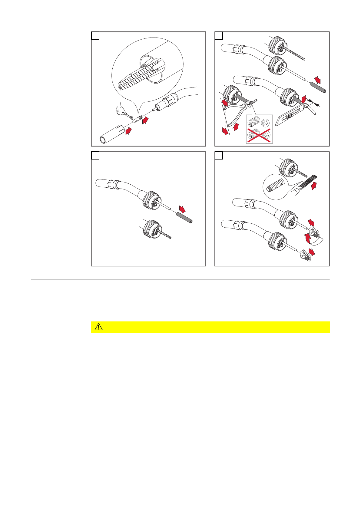
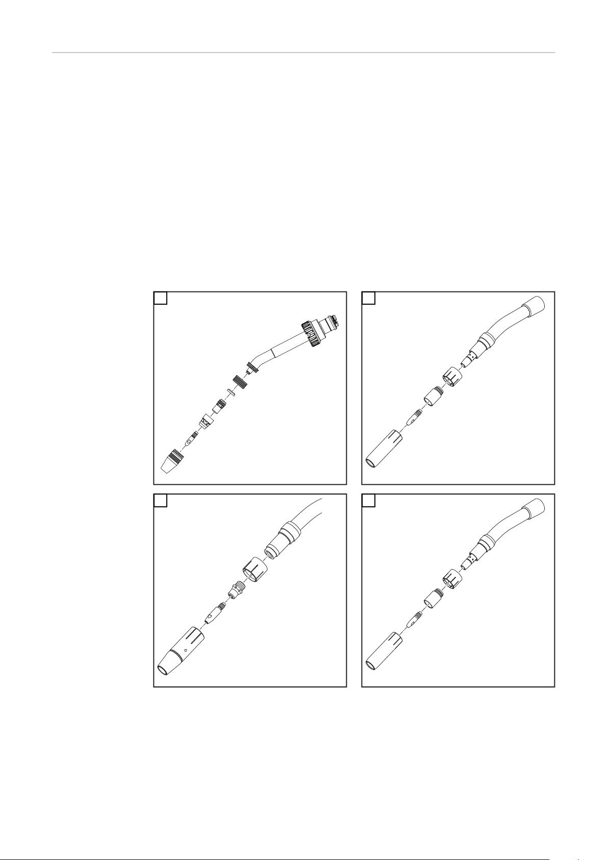
Draht-Führungseinsatz montieren
WICHTIG! Ausschließlich Kontaktrohre mit Zentrierbohrung verwenden!
* Der Draht-Führungseinsatz 44,0350,1806 kann bei einem Robacta 280 45°Brennerkörper nur von vorne montiert und demontiert werden.
WICHTIG! Beim Ablängen des Draht-Führungseinsatzes darauf achten, dass
das Kontaktrohr im Rohrbogen fest montiert ist
-
der Draht-Führungseinsatz satt am Kontaktrohr anliegt
-
Grate auf der Innenseite des Draht-Führungseinsatzes entfernen.
-
Zum Ablängen eines Draht-Führungseinsatzes aus Stahl die Kraftzange Art. Nr.
42,0435,0009 verwenden.
1
2
9

"CB"
2
1
3
0 m
m
.0 i
nch
1
2
3
2
2
1
1
1
2
4
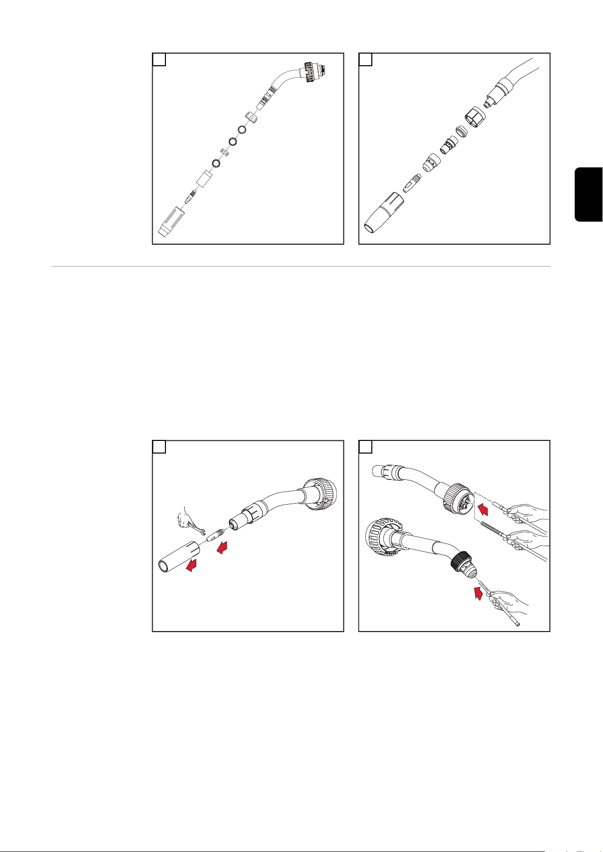
Verschleißteile
an der Antriebseinheit montieren
5
6
WICHTIG! Beim Aufsetzen des Rohrbogens auf die Robacta Drive CMT Kuppel-
stelle folgendes beachten: der Draht-Führungseinsatz muss knickfrei in das Auslaufstück an der Robacta Drive CMT Kuppelstelle gleiten.
VORSICHT!
Gefahr von Kühlmittel-Austritt.
Schwerwiegende Schäden können die Folge sein.
Beim Montieren des Rohrbogens auf festen Sitz der Überwurfmutter achten.
▶
WICHTIG! Für das Lösen und Festziehen der Antriebsrollen nur das mitgelieferte Arretierwerkzeug verwenden.
10

2
1
1
1
2
2
4
3
1
5
1
4
3
2
3
4
1
2
1
2
2
DE
3
5
4
6
11

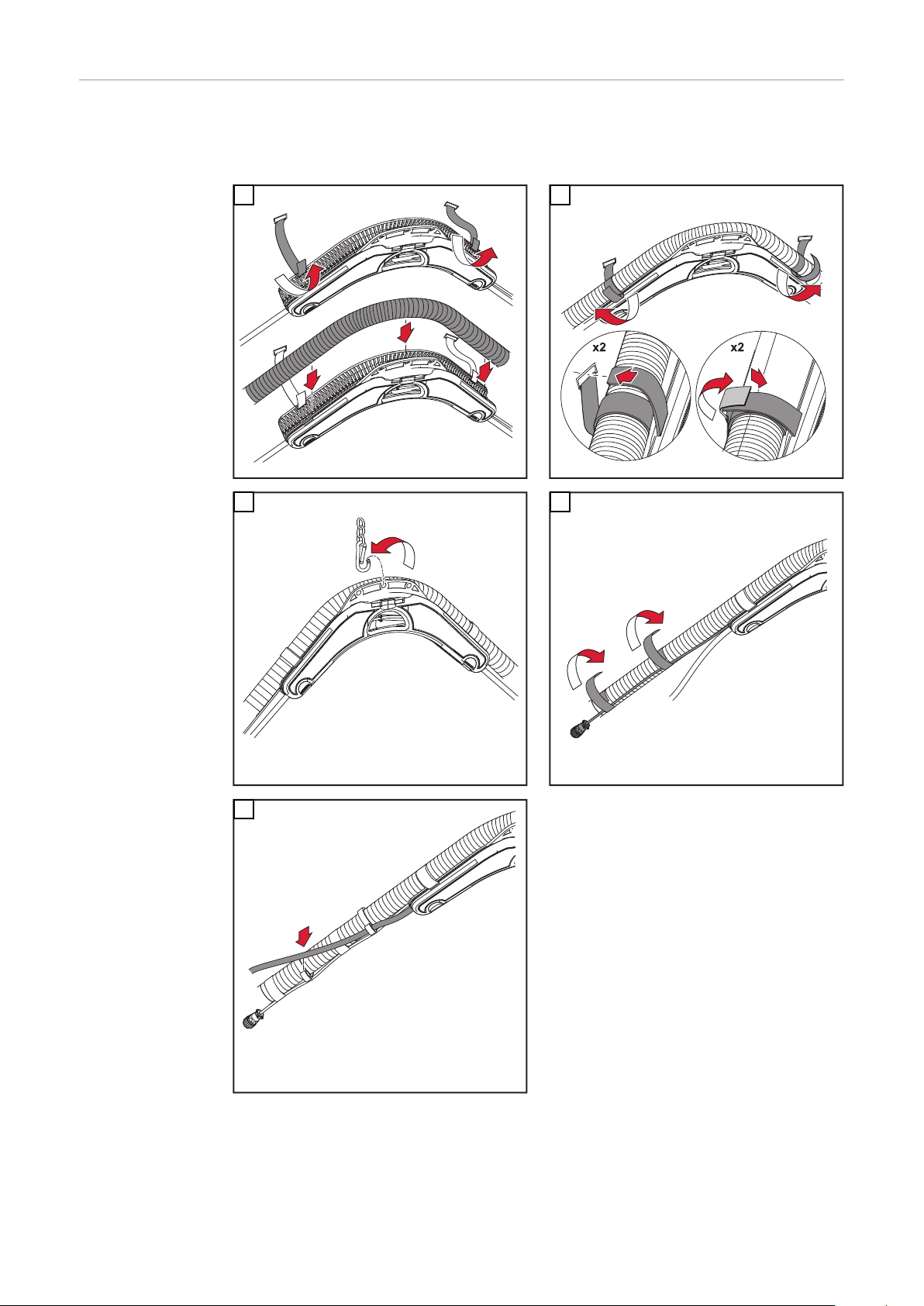
Schlauchpaket
2
1
1
4
3
5
2
2
*
1
2
2
*
2
1
**
max.
3
5
4
5
1
2
3
4
2
1
montieren und
anschließen
WICHTIG! Bei Montage des Schlauchpaketes Anschlusskabel in Ausnehmung
verlegen (Abb.5). Auf richtigen Anschluss der Steckanschlüsse achten.
* Drehmoment: 3,0 Nm
** Drehmoment: 1,5 Nm
1
3
2
4
5
12
6

PAP Schlauch-
1
*
1
2
*
3
2
1
**
**
2
1
3
3
1
2
3
4
paket montieren
und anschließen
WICHTIG! Bei Montage des Schlauchpaketes Anschlusskabel in Ausnehmung
verlegen (Abb.5). Auf richtigen Anschluss der Steckanschlüsse achten.
* Drehmoment: 3,0 Nm
** Drehmoment: 3,0 Nm
WICHTIG! Der Draht-Förderschlauch darf nicht aus dem Schlauchpaket gezogen werden. Der Wiedereinbau ist nur durch Fronius möglich.
DE
1
3
2
4
5
6
13
Drahtpuffer an-
3
3
3
1
2
5
3
2
1
4
1
1
2
1
schließen
WICHTIG! Draht-Förderschlauch zwischen Drahtpuffer und Robacta Drive CMT
keiner Zugspannung aussetzen.
1
3
2
4
5
14

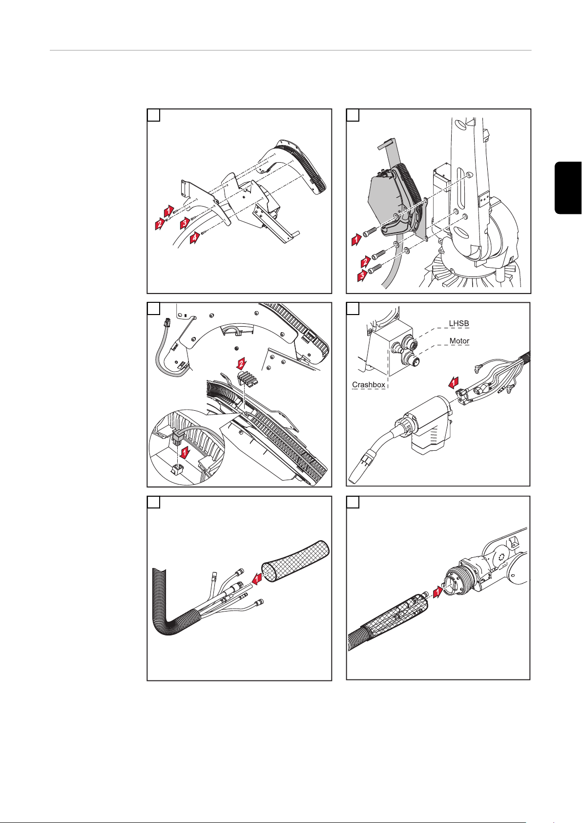
RA Drive CMT-
*
PAP W FL anschließen
* Detaillierte Daten zur Montage an den jeweiligen Robotertypen entnehmen Sie
dem Beiblatt „Schlauchpaket CMT mit Drahtpuffer am Roboter montieren“
(42,0410,1518).
DE
1
3 4
2
5 6
15

7 8
1
2
3
4
5
6
1
2
9 10
11
12
16

13 14
DE
15
WICHTIG! Draht-Förderschlauch zwi-
schen Drahtpuffer und Robacta Drive
CMT-PAP W keiner Zugspannung aussetzen.
17

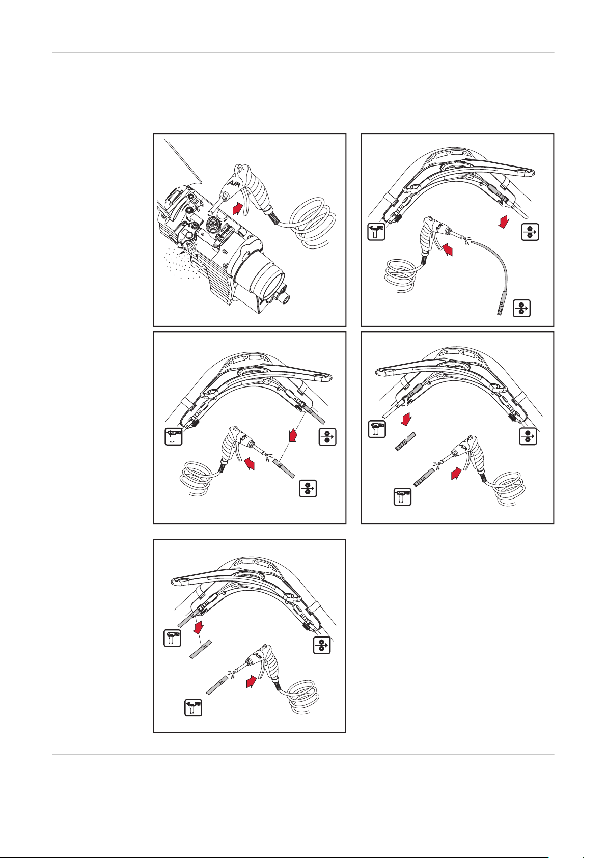
Schweißbrenner
**
*
1
5
7
6
3
4
2
AIR
OUT
2
**
AIR
OUT
1
2
1
2
"click"
2
1
anschließen
WICHTIG! Beim Anschließen des Schweißbrenners kontrollieren ob
sämtliche Anschlüsse fest angeschlossen sind
-
sämtliche Kabel, Leitungen, und Schlauchpakete unbeschädigt und korrekt
-
isoliert sind.
* Steuerleitung Drahtpuffer
** Option Brenner ausblasen
WICHTIG! Bei Nichtverwendung der Option Brenner ausblasen auf dichten Verschluss der Ausblasleitung achten.
Externen DrahtFörderschlauch
anschließen
1
2
VORSICHT!
Beschädigungsgefahr des Draht-Förderschlauches durch Hängenbleiben.
Schwerwiegende Schäden können die Folge sein.
Draht-Förderschlauch so am Schlauchpaket befestigen, dass ein Hängenblei-
▶
ben an umliegenden Geräten oder Bauteilen nicht möglich ist (Abb. 3 + 6).
18
HINWEIS!
Abbildung 4 + 5 gilt nicht für Roboter-Schweißbrenner (PAP)
1
2

1
3
2
1
"click"
1
2
2
4
DE
Richtige Verlegung des Roboter-Schlauchpaketes
5
6
Um eine optimale Drahtförderung zu erreichen, bei der Verlegung des Schlauchpaketes folgendes beachten:
Schlauchpakt nicht knicken
-
Schlauchpaket nicht überstrecken
-
Biegeradien im Schlauchpaket so groß wie möglich halten
-
Drahtpuffer nach Möglichkeit mittels Balancer zentral über dem Roboterarm
-
positionieren
19

Um eine optimale Drahtförderung zu erreichen, bei der Verlegung des Schlauchpaketes folgendes beachten:
Bei fix montiertem Drahtpuffer den vorderen Teil des Schlauchpaketes mit-
-
tels Balancer aufhängen
Schlauchpaket-Halterungen verwenden (z.B.: Schlauchpaket-Halterung Uni-
-
versal)
Je nach Platzangebot Knickschutz-Feder verwenden
-
Maximale Achsrotation PAP
20

Bedienelemente
*
1
2
1
und Funktionen
WARNUNG!
Gefahr durch austretende Drahtelektrode.
Schwere Personenschäden können die Folge sein.
Schweißbrenner so halten, dass die Schweißbrenner-Spitze von Gesicht und
▶
Körper weg zeigt.
WICHTIG! Drahtelektrode vor dem Einfädeln entgraten! Beim Einfädeln von weichen Drahtelektroden (AlSi 5, Al, und AlMg) Spannhebel öffnen.
* LED leuchtet
- grün: Betriebsbereit
- rot: keine Steuersignal-Verbindung
WICHTIG! Leuchtet LED nicht: Stromversorgung Antriebseinheit überprüfen.
DE
1
3
2
4
21

1 2 3 4
5
2,5
1
Fdi
(m/min)
(ipm)
t (s)
2
1
5
1
-
+
1
2
Al- AlSi 80-120N
6
Anpressdruck
einstellen
VORSICHT!
Verletzungsgefahr durch rotierende Vorschubrollen.
Schwere Personenschäden können die Folge sein.
Nicht in die Vorschubrollen greifen.
▶
WICHTIG! Das Justieren der Einstellschraube ist nur bei eingefädelter Drahtelektrode zulässig. Angegebene Werte gelten im geschlossenem Zustand.
1
2
22

AlMg 100-150N
3
Fe, CrNi, CuSi 150-200N
2
1
22°
*
2
1
4
DE
Haltewinkel
wechseln
WICHTIG! Beim Montieren des Haltewinkels Robacta Drive CMT flex (22° / 36°)
darauf achten, dass die Montagemarke der gewünschten Neigung mit der Montagemarke an Robacta Drive CMT übereinstimmt (TCP in 6. Roboterachse).
* Drehmoment: 2,4 Nm
1
2
Verschleißteile
am Rohrbogen
wechseln
VORSICHT!
Verbrühungsgefahr durch heißes Kühlmittel.
Schwere Personenschäden können die Folge sein.
Vor Abnehmen des Rohrbogens Netzschalter an der Stromquelle in Stellung
▶
-O- schalten.
WICHTIG! Kühlmittel-Austritt vermeiden. Beim Abnehmen des Rohrbogens von
der Robacta Drive Kuppelstelle folgendes beachten:
Drahtelektrode beim Kontaktrohr ablängen
-
Rohrbogen hineindrücken und halten
-
Überwurfmutter vollständig lösen
-
Rohrbogen mit schneller Bewegung gerade abziehen
-
23

1
2
3
1
1
2
3
2
1
3
4
5
6
0 mm
.
0
inch
3
2
6
2
1
1
1
1
2
2
3
5
4
6
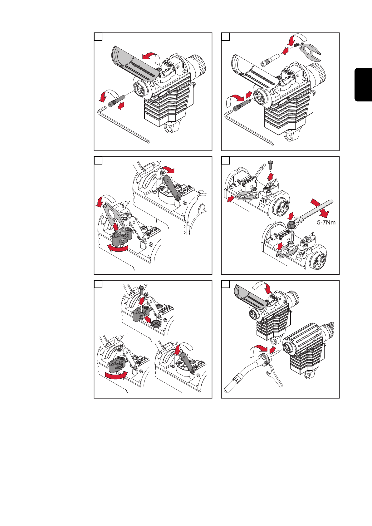
Robacta Drive
CMT Pro
Gasdüsen-Positionsset wechseln
24
Verbrennungsgefahr durch heißen Rohrbogen.
Schwere Personenschäden können die Folge sein.
▶
▶
VORSICHT!
Vor dem Wechseln des Gasdüsen-Positionsset Rohrbogen abkühlen lassen.
Netzschalter an der Stromquelle in Stellung -O- schalten.

WICHTIG! Vor der Montage des Gasdüsen-Positionsset muss die Überwurfmut-
1
2
3
4
1
2
3
4
**
***
*
*
1
2
3
4
3
4
2
1
ter (*) am Rohrbogen sein.
* Überwurfmutter
Kabel richtig positionieren:
** Gasdüsen-seitig
*** Antriebseinheit-seitig
DE
1
3
2
4
5
25

Pflege, Wartung und Entsorgung
Allgemeines Regelmäßige und vorbeugende Wartung des CMT Roboter-Schweißbrenners sind
wesentliche Faktoren für einen störungsfreien Betrieb. Der Schweißbrenner ist
hohen Temperaturen und starker Verunreinigung ausgesetzt. Daher benötigt der
Schweißbrenner eine häufigere Wartung als andere Komponenten des
Schweißsystems.
WICHTIG! Vermeiden Sie beim Entfernen von Schweißspritzern Riefen und Kratzer. Darin könnten sich im weiteren Betrieb entstehende Schweißspritzer nachhaltig festsetzen.
den Rohrbogen keinesfalls biegen
-
26

Bei jeder Inbe-
1
2
triebnahme
Kontaktrohr kontrollieren
-
Ausgeschliffenes Kontaktrohr austauschen
-
Gasdüse von Schweißspritzern befreien (z.B. manuell, durch Ausblasen oder
-
automatisiert mit Robacta Reamer oder Robacta TC 1000)
Bei nicht entfernbaren Verunreinigungen im Steckbereich Gasdüse austau-
-
schen
Wasseranschlüsse auf Dichtheit prüfen
-
Wasserrückfluss-Menge im Kühlmittel-Behälter überwachen, ggf. Kühlgerät
-
entlüften
* Spritzerschutz oder Isolationen auf Beschädigung prüfen
DE
27
Bei jedem Aus-
1
2
2
1
1
2
3
2
tausch der
Draht-Spule
Draht-Führungsseelen mit reduzierter Druckluft ausblasen
-
Empfohlen: Draht-Führungsseele austauschen (mind. alle 4 Monate)
-
Vorschubrollen kontrollieren und gegebenenfalls austauschen
-
Draht-Förderschlauch und Antriebseinheit mit reduzierter Druckluft reinigen
-
Entsorgung Elektro- und Elektronik-Altgeräte müssen gemäß Europäischer Richtlinie und na-
tionalem Recht getrennt gesammelt und einer umweltgerechten Wiederverwer-
28

tung zugeführt werden. Gebrauchte Geräte sind beim Händler oder über ein lokales, autorisiertes Sammel- und Entsorgungssystem zurückzugegeben. Eine
fachgerechte Entsorgung des Altgeräts fördert eine nachhaltige Wiederverwertung von stofflichen Ressourcen. Ein Ignorieren kann zu potenziellen Auswirkungen auf die Gesundheit/Umwelt führen.
Verpackungsmaterialien
Getrennte Sammlung. Prüfen Sie die Vorschriften Ihrer Gemeinde. Verringern
Sie das Volumen des Kartons.
Gewährleistung Der CMT Roboter-Schweißbrenner Robacta Drive CMT ist ausgelegt für automa-
tisierte Anwendungen in Verbindung mit einer Kollisionsbox und üblichen
Schweißgeschwindigkeiten.
Für andere Anwendungen übernimmt Fronius International GmbH keine Gewährleistung.
HINWEIS!
Das Öffnen versiegelter Schrauben kann zur Beschädigung der Antriebseinheit
führen. Werden versiegelte Schrauben geöffnet, übernimmt Fronius International GmbH keine Gewährleistung.
DE
29

Fehlerdiagnose, Fehlerbehebung
Fehlerdiagnose,
Fehlerbehebung
kein Schweißstrom
Netzschalter eingeschaltet, Anzeigen an der Stromquelle leuchten, Schutzgas
vorhanden
Ursache:
Behebung:
Ursache:
Behebung:
Ursache:
Behebung:
Robacta Drive CMT arbeitet nicht
Netzschalter eingeschaltet, Anzeigen an der Stromquelle leuchten
Ursache:
Behebung:
Ursache:
Behebung:
Masseanschluss falsch
Masseanschluss und Klemme auf Polarität überprüfen
Stromkabel im Robacta Drive CMT Schlauchpaket unterbrochen
Service-Dienst verständigen
Loser Anschluss des Schlauchpaketes
Anschluss des Schlauchpaketes auf festen Sitz überprüfen
Steuerstecker oder Motorstecker nicht eingesteckt
Steuerstecker oder Motorstecker einstecken
Steuerleitung oder Motorleitung defekt
Service-Dienst verständigen
Ursache:
Behebung:
Ursache:
Behebung:
kein Schutzgas
alle anderen Funktionen vorhanden
Ursache:
Behebung:
Ursache:
Behebung:
Ursache:
Behebung:
Ursache:
Behebung:
Ursache:
Behebung:
Antriebseinheit defekt
Service-Dienst verständigen
Verbindungs-Schlauchpaket defekt oder nicht korrekt angeschlossen
Verbindungs-Schlauchpaket und Anschluss überprüfen
Gasflasche leer
Gasflasche wechseln
Gasdruckminderer defekt
Gasdruckminderer tauschen
Gasschlauch nicht montiert oder schadhaft, geknickt
Gasschlauch montieren, ausbiegen oder tauschen
Schweißbrenner defekt
Schweißbrenner austauschen
Gas-Magnetventil im CMT-Vorschub defekt
Gas-Magnetventil im CMT-Vorschub austauschen
30

schlechte Schweißeigenschaften
Ursache:
Behebung:
falsche Schweißparameter
Einstellungen überprüfen
DE
Ursache:
Behebung:
Ursache:
Behebung:
Ursache:
Behebung:
Ursache:
Behebung:
Ursache:
Behebung:
Ursache:
Behebung:
Ursache:
Behebung:
Masseverbindung schlecht
guten Kontakt zum Werkstück herstellen
kein oder zu wenig Schutzgas
Druckminderer, Gasschlauch, Gas-Magnetventil und Brenner-Gasan-
schluss überprüfen. Bei gasgekühlten Schweißbrennern Gasabdichtung überprüfen, geeignete Draht-Führungsseele verwenden.
Anschlüsse undicht
Anschlüsse festziehen
unpassendes oder beschädigtes Kontaktrohr
Kontaktrohr wechseln
falsche Drahtlegierung oder falscher Drahtdurchmesser
eingelegte Drahtspule kontrollieren; Verschweißbarkeit des Grund-
Werkstoffes prüfen
Schutzgas für Drahtlegierung nicht geeignet
korrektes Schutzgas verwenden
Ungünstige Schweißbedingungen: Schutzgas verunreinigt (Feuchtigkeit, Luft), mangelhafte Gasabschirmung (Schmelzbad „kocht“, Zugluft), Verunreinigungen im Werkstück (Rost, Lack, Fett)
Schweißbedingungen optimieren
Ursache:
Behebung:
Ursache:
Behebung:
Ursache:
Behebung:
Ursache:
Behebung:
Ursache:
Behebung:
Ursache:
Behebung:
verunreinigte Gasdüse
Schweißspritzer entfernen
Turbulenzen auf Grund zu hoher Schutzgasmenge
Schutzgas-Menge reduzieren, empfohlen:
Schutzgas-Menge (l/min) = Drahtdurchmesser (mm) x 10
(z.B. 16 l/min für 1,6 mm Schweißdraht)
zu großer Abstand zwischen Kontaktrohr und Werkstück.
Abstand zwischen Kontaktrohr und Werkstück reduzieren (empfoh-
len: 10 - 15 mm)
zu großer Anstellwinkel des Schweißbrenners
Anstellwinkel des Schweißbrenners reduzieren
Draht-Förderkomponenten mit falschem Durchmesser
Richtige Draht-Förderkomponenten einsetzen
Gasverlust oder Fremdluft
Dichtheit Ausblasleitung und Ausblasventil prüfen. Verschluss der
Ausblasleitung überprüfen (Stecknippel)
31

schlechte Drahtförderung
Ursache:
Behebung:
Drahteinlauf passt nicht
Position der Draht-Einlaufdüse zu den Vorschubrollen überprüfen
und korrigieren
Ursache:
Behebung:
Ursache:
Behebung:
Ursache:
Behebung:
Ursache:
Behebung:
Ursache:
Behebung:
Ursache:
Behebung:
Ursache:
Behebung:
Bremse am CMT-Drahtvorschub zu fest eingestellt
Bremse am CMT-Drahtvorschub lockerer einstellen
Bohrung des Kontaktrohres auf Grund von Ablagerungen verkleinert
Kontaktrohr austauschen
Draht-Förderseele oder Draht-Führungseinsatz defekt
Draht-Förderseele und Draht-Führungseinsatz auf Knicke, Ver-
schmutzung, etc. prüfen; defekte Draht-Führungsseele oder DrahtFührungseinsatz austauschen
Vorschubrollen für verwendete Drahtelektrode nicht geeignet
passende Vorschubrollen verwenden
falscher Anpressdruck der Vorschubrollen
Anpressdruck überprüfen, gegebenenfalls neu einstellen
Vorschubrollen verunreinigt oder beschädigt
Vorschubrollen reinigen oder austauschen
Draht-Führungsseele wurde beim Einschieben geknickt
Draht-Führungsseele beim Einschieben nur in der Nähe des Einlauf-
rohres anfassen
Ursache:
Behebung:
Ursache:
Behebung:
Ursache:
Behebung:
Schweißbrenner wird sehr heiß
Ursache:
Behebung:
Ursache:
Behebung:
Ursache:
Behebung:
Draht-Führungsseele nach dem Ablängen zu kurz
Draht-Führungsseele austauschen und auf korrekte Länge kürzen
Abrieb des Drahtelektrode infolge von zu starkem Anpressdruck an
den Vorschubrollen
Anpressdruck an den Draht-Förderrollen reduzieren
Drahtelektrode verunreinigt / angerostet
Hochwertigen Drahtelektrode ohne Verunreinigungen verwenden
Überwurfmutter am Anschluss-Rohrbogen locker
Überwurfmutter festziehen
Schweißbrenner wurde über die maximale Einschaltdauer hinaus betrieben.
Schweißleistung herabsetzen oder leistungsfähigeren Schweißbrenner verwenden; Einschaltdauer und Belastungsgrenzen beachten
Kühlmittel-Durchfluss zu gering
Kühlmittel-Stand, Kühlmittel-Durchflussmenge, Kühlmittel-Ver-
schmutzung, Verlegung des Schlauchpaketes etc. kontrollieren
32

Kurze Lebensdauer des Kontaktrohres
Ursache:
Behebung:
Abrieb der Drahtelektrode infolge von zu starkem Anpressdruck an
den Vorschubrollen
Anpressdruck an den Vorschubrollen reduzieren
DE
Ursache:
Behebung:
Ursache:
Behebung:
Ursache:
Behebung:
HINWEIS!
Bei CrNi-Anwendungen kann auf Grund der Oberflächen-Beschaffenheit der
CrNi-Drahtelektrode ein höherer Kontaktrohr-Verschleiß auftreten.
Draht-Fördertasten funktionieren nicht
Ursache:
Behebung:
Ursache:
Behebung:
Falsche Dimension des Kontaktrohres
Kontaktrohr korrekt dimensionieren
Zu lange Einschaltdauer des Schweißbrenners
Einschaltdauer herabsetzen oder leistungsfähigeren Schweißbrenner
verwenden
Kontaktrohr überhitzt. Keine Wärmeableitung auf Grund zu losen
Sitzes des Kontaktrohres
Kontaktrohr festziehen
Steckerverbindungen „Steuerleitung / Stromquelle“ fehlerhaft
Steckerverbindung überprüfen / Servicedienst verständigen
Steuerleitung ist defekt
Steuerleitung austauschen / Servicedienst verständigen
33

Porosität der Schweißnaht
Ursache:
Behebung:
Verunreinigte Gasdüse, dadurch unzureichender Gasschutz der
Schweißnaht
Schweißspritzer entfernen
Ursache:
Behebung:
Ursache:
Behebung:
Ursache:
Behebung:
Ursache:
Behebung:
Ursache:
Behebung:
Ursache:
Behebung:
Ursache:
Behebung:
Löcher im Schutzgas-Schlauch oder ungenaue Anbindung des
Schutzgas-Schlauches
Schutzgas-Schlauch austauschen, für exakte Anbindung des Schutzgas-Schlauches sorgen
O-Ringe an den Anschlüssen sind defekt
O-Ringe austauschen
Feuchtigkeit / Kondensat in der Schutzgas-Leitung
Schutzgas-Leitung trocknen
Zu starke oder zu geringe Schutzgas-Strömung
Schutzgas-Strömung korrigieren
Ungenügende Schutzgas-Menge zu Schweißbeginn oder Schweißende
Gas-Vorströmung und Gas-Nachströmung erhöhen
Rostige oder schlechte Qualität der Drahtelektrode
Hochwertige Drahtelektrode ohne Verunreinigungen verwenden
Zu viel Trennmittel aufgetragen
Überschüssiges Trennmittel entfernen / weniger Trennmittel auftra-
gen
34

Technische Daten
Ø
Ø
Ø
CMT Symbolerklärung
Wasserkühlung
Schlauchpaket-Länge
X Einschaltdauer in %
DE
X / I
40°C)
M21 (EN 439)
X / I
40°C)
C1 (EN 439)
(10 min /
max
(10 min /
max
I
max
* geringste Kühlleistung laut Norm IEC 60974-2,
Spannungsbemessung (V-Peak):
für maschinellgeführte Schweißbrenner: 141 V
-
Das Produkt entspricht den Anforderungen laut Norm IEC 60974-7.
Robacta 300 Robacta 500 Robacta 700
[%] / [A]
[%] / [A]
[%] / [A]
[%] / [A]
[%] / [A]
[%] / [A]
[mm]
[in.]
max. Schweißstrom in A
Elektrodendurchmesser
abhängig von der Schlauchpaket-Länge
-
100 / 350
-
100 / 350
0,8 - 1,2
.031 - .047
-
100 / 500
-
100 / 500
0,8 - 1,6
.031 - .063
-
100 / 700
-
100 / 700
1,0 - 1,6
.039 - .063
X / I
40°C)
M21 (EN 439)
X / I
40°C)
C1 (EN 439)
(10 min /
max
(10 min /
max
Robacta 5000 Robacta 7000 Robacta Twin Com-
pact PRO
[%] / [A]
[%] / [A]
[%] / [A]
[%] / [A]
[%] / [A]
[%] / [A]
[mm]
[in.]
-
100 / 500
-
100 / 500
0,8 - 1,6
.031 - .063
-
100 / 700
-
100 / 700
1,0 - 1,6
.039 - .063
-
100 / 900
-
100 / 900
1,0 - 1,6
.039 - .063
35

Ø
X / I
(10 min /
max
40°C)
M21 (EN 439)
Robacta Drive CMT/PAP Robacta Drive CMT Twin
[%] / [A]
[%] / [A]
[%] / [A]
40 / 500
60 / 450
100 / 360
-
100 / 720 (2 x 360)
X / I
(10 min /
max
40°C)
C1 (EN 439)
P
*
min
Q
min
P
min
Q
min
[%] / [A]
[%] / [A]
[%] / [A]
[mm]
[in.]
[m] ([W])
[ft.] ([W])
[L/min]
[gal./min]1.26 [US]
[bar]
[psi.]
[bar]
[psi.]
[V] DC 55 55
[A] 2,5 2,5
[min]
[ipm.]
40 / 500
60 / 450
100 / 360
0,8 - 1,2 (Alu 1,6)
.031 - .047 (Alu .063)
4,25 (800) / 6,25 (1100) /
8,25 (1400)
13.9 (800) / 20.5 (1100) / 27
(1400)
3
43
5,5
79.74
0,5 - 22
16.69 - 866.14
-
100 / 720 (2 x 360)
0,8 - 1,2 (Alu 1,6)
.031 - .047 (Alu .063)
4,25 (1950) / 6,25 (2500) /
8,25 (3100)
13.9 (1950) / 20.5 (2500) / 27
(3100)
1
.26 [US]
3
43
5,5
79.74
0,5 - 22
16.69 - 866.14
36

Contents
Safety 38
Safety 38
Installation and commissioning 40
Device concept 40
Original equipement and tools 40
Robacta Drive CMT Pro basic version 41
Recommended torch necks 42
Fitting the wire guide insert 43
Install Wear Parts on Drive Unit 44
Fitting and connecting the hosepack 46
Fitting and connecting the PAP hosepack 47
Connecting the wire buffer 48
Connecting the RA Drive CMT-PAP W FL 49
Connecting the welding torch 52
Connecting an external wirefeeding hose 52
Correct laying of the robot hose pack 53
Maximum PAP axis rotation 54
Controls and functions 55
Set Contact Pressure 56
Changing the fixing bracket 57
Replace Wear Parts on Torch Neck 57
Robacta Drive CMT Pro - Change gas nozzle positioning kit 58
Care, maintenance and disposal 60
General 60
Every start-up 61
Every time the wirespool is changed 62
Disposal 62
Liability 63
Troubleshooting 64
Troubleshooting 64
Technical data 68
CMT 68
EN
37

Safety
Safety
WARNING!
Danger from incorrect operation and work that is not carried out properly.
This can result in serious personal injury and damage to property.
All the work and functions described in this document must only be carried
▶
out by technically trained and qualified personnel.
Read and understand this document in full.
▶
Read and understand all safety rules and user documentation for this device
▶
and all system components.
WARNING!
Danger from electrical current.
This can result in serious personal injury and damage to property.
Before starting work, switch off all devices and components involved and dis-
▶
connect them from the grid.
Secure all devices and components involved so they cannot be switched back
▶
on.
WARNING!
Danger from electric current due to defective system components and incorrect operation.
This can result in serious personal injury and damage to property.
All cables, leads and hosepacks must always be securely connected, unda-
▶
maged and correctly insulated.
Only use adequately dimensioned cables, leads and hosepacks.
▶
WARNING!
Risk of coolant escaping.
This can result in serious personal injury and damage to property.
When disconnecting a welding torch from the cooling unit or other system
▶
components, always seal the coolant hoses using the plastic seal attached to
the torch.
WARNING!
Danger due to hot system components and/or equipment.
Can result in serious burns or scalding.
Before starting work, allow all hot system components and/or equipment to
▶
cool to +25°C/+77°F (e.g., coolant, water-cooled system components, wirefeeder drive motor, etc.)
Wear suitable protective equipment (e.g., heat-resistant gloves, safety gog-
▶
gles, etc.) if cooling down is not possible.
38

WARNING!
Danger from contact with toxic welding fumes.
This can result in serious personal injuries.
Always extract welding fumes.
▶
Ensure an adequate supply of fresh air. Ensure that there is a ventilation rate
▶
of at least 20 m³ (169070.1 US gi) per hour at all times.
If in doubt, a safety engineer should be commissioned to check the pollution
▶
level in the workplace.
CAUTION!
Danger from operation without coolant.
This can result in damage to property.
Never operate water-cooled welding torches without coolant.
▶
During welding, ensure that the coolant is circulating correctly – this will be
▶
the case for Fronius cooling units if a regular return flow of coolant can be
seen in the coolant container of the cooling unit.
The manufacturer will not be liable for any damages due to non-observance
▶
of the above mentioned points. All claims against the warranty are void.
CAUTION!
EN
Danger of burns from hot surface.
Serious personal injuries may result.
When the ambient temperature in operation is at its maximum of 40°C, the
▶
surface temperature of the Robacta Drive CMT can rise as high as 90°C. This
is a normal operating temperature and does not endanger the Robacta Drive
CMT.
39

Installation and commissioning
1x
1x
1x
0,9 1,0
.035 .047
mm
inch
1x 1x 1x
3x
1x
"CB" "CB"
Al
1,2 1,6
.039 .063
a)
)b)b
3x
1x
1x
1x
1x
0,8 0,9
.032 .039
mm
inch
1x 1x 1x
3x
1x
"CB" "CB"
1,0 1,2
.035 .047
c)
)d)d
3x
1x
Steel
CuSi
Device concept The Robacta Drive CMT robot welding torch consists of atorch neck, drive unit
with fixing bracket and hosepack.
In combination with the wire buffer on the hosepack, the integral wire drive motor can quickly reverse the welding wire. The external wirefeed means that all
wirefeed components can be replaced quickly. Many different torch neck designs
facilitate easy access to the weld.
Robacta Drive CMT is especially suited to:
General light-gauge sheet applications
-
Spatter-free MIG brazing of galvanized light-gauge sheets
-
Joining steel to aluminium.
-
Original equipement and tools
In order to operate the Robacta Drive CMT, original equipment that corresponds
to the wire diameter and to the filler metal is required (see spare parts list):
Original equipment aluminium
-
Original equipment steel/CuSi
-
Original equipment CrNi
-
a) Graphite with end piece
b) Graphite
c) Bronze
d) Steel
40

1x
1x1x
0,8 0,9
.032 .039
mm
inch
1x 1x 1x
3x
1x
"CB" "CB"
1,0 1,2
.035 .047
c)
)b)b
3x
1x
CrNi
*
(1.60 in
.)
4
0
mm
2x
Tools:
**
*
Flat spanner, size 10/12
-
Locking spanner, size 13
-
Cutting pipe (for cutting the wire guide insert to length)
-
Allen key, size 3
-
* „Spanner for union nut“ (optional)
EN
Robacta Drive
CMT Pro basic
version
* Blade terminal on housing
** Gas nozzle positioning kit
incl.
- 290 mm sensor cable
- 430 mm sensor cable
(depending on length and bend in the torch neck)
41

Recommended
torch necks
(1)
(2)
(3)
(4)
(5)
(6)
Robacta 2801) : 22°
Robacta 3001) : 22°, 36°
Robacta 4001) : 22°, 36°
Robacta 5002) : 22°, 36°
Robacta 7002) : 22°, 36°
Robacta 50002) : 22°, 36°
Contact tubes required:
1)
M8 CB contact tube (with centre hole)
2)
M10 CB contact tube (with centre hole)
The following assembly steps are explained using a Robacta 300 / 500 as the example. Assembly with other torch necks is carried out in a similar manner.
1 2
3 4
42

5 6
1
2
*
Robacta 280 45°
1
1
EN
Fitting the wire
guide insert
IMPORTANT! Use only contact tubes with centre holes.
* If a Robacta 280 45° torch body is being used, the wire guide 44,0350,1806 can
only be fitted and removed from the front.
IMPORTANT! When cutting the wire guide insert to length, make sure that
the contact tube is firmly attached to the torch neck
-
the wire guide insert butts right up against the contact tube
-
Deburr the inside of the wire guide insert.
-
Use the power tong (item no. 42,0435,0009) to shorten the steel wire guide.
1
2
43
"CB"
2
1
3
0 m
m
.0 i
nch
1
2
3
2
2
1
1
1
2
4
Install Wear
Parts on Drive
Unit
5
6
IMPORTANT! Take care to ensure the following when attaching the torch neck to
the Robacta Drive CMT coupling point: the wire guide insert must slide into the
outlet section on the Robacta Drive CMT coupling point without kinking.
CAUTION!
Risk of coolant escaping.
This can result in damage to property.
Ensure union nut fits tightly when assembling torch neck.
▶
IMPORTANT! Use only the locking tool supplied with the system to undo and
tighten the drive rollers.
44
2
1
1
1
2
2
4
3
1
5
1
4
3
2
3
4
1
2
1
2
2
EN
3
5
4
6
45

Fitting and con-
2
1
1
4
3
5
2
2
*
1
2
2
*
2
1
**
max.
3
5
4
5
1
2
3
4
2
1
necting the hosepack
IMPORTANT! When fitting the hosepack, lay the connection cable in the recess
(Fig. 5). Be sure to connect the plug connectors correctly.
* Torques: 3.0 Nm
** Torques: 1,5 Nm
1
3
2
4
5
46
6

Fitting and con-
1
*
1
2
*
3
2
1
**
**
2
1
3
3
1
2
3
4
necting the PAP
hosepack
IMPORTANT! When fitting the hosepack, lay the connection cable in the recess
(Fig. 5). Be sure to connect the plug connectors correctly.
* Torques: 3,0 Nm
** Torques: 3,0 Nm
IMPORTANT! The wirefeeding hose must not be pulled out of the hosepack. Refitting can only be performed by Fronius.
1
3
2
4
EN
5
6
47

Connecting the
3
3
3
1
2
5
3
2
1
4
1
1
2
1
wire buffer
IMPORTANT! Do not subject the wirefeeding hose between the wire buffer and
the Robacta Drive CMT to tensile stress.
1
3
2
4
5
48

Connecting the
*
RA Drive CMTPAP W FL
* For detailed information on fitting the hosepack to the respective robot types,
please refer to the „Fitting the CMT hosepack with wire buffer to the robot“ leaflet (42,0410,1518).
1
3 4
2
EN
5 6
49

7 8
1
2
3
4
5
6
1
2
9 10
11
12
50

13 14
EN
15
IMPORTANT! Do not subject the wire-
feeding hose between the wire buffer
and the Robacta Drive CMT-PAP W to
tensile stress.
51

Connecting the
**
*
1
5
7
6
3
4
2
AIR
OUT
2
**
AIR
OUT
1
2
1
2
"click"
2
1
welding torch
IMPORTANT! When connecting the torch check that
all connections are firmly made
-
all cables, pipes and hose packs are undamaged and correctly insulated.
-
* Control cable for wire buffer
** Torch blow-through option
IMPORTANT! Ensure the blowthrough line is tightly sealed if the torch blowthrough option is not being used.
Connecting an
external wirefeeding hose
1
2
CAUTION!
Risk of damage to dangling wirefeed hose.
This can result in damage to property.
Fasten the wirefeed hose to the hosepack in such a way that it cannot dangle
▶
close to surrounding machines or components (Fig. 3 + 6).
52
NOTE!
Figures 4 + 5 do not apply to robot welding torches (PAP)
1
2

1
3
2
1
"click"
1
2
2
4
EN
Correct laying of
the robot hose
pack
5
6
To attain optimum wirefeed, observe the following when laying the hose pack:
Do not kink the hose pack
-
Do not overstretch the hosepack
-
Keep bends in the hose pack as wide as possible
-
Where possible, use the balancer to position the wire buffer centrally above
-
the robot arm
To attain optimum wirefeed, observe the following when laying the hose pack:
53

For fixed wire buffers, suspend the front of the hosepack using the balancer
-
Use hose pack holders (e.g.: Universal hose pack holder)
-
If there is enough room, use the anti-kink protection spring
-
Maximum PAP
axis rotation
54

Controls and
*
1
2
1
functions
WARNING!
Danger from welding wire emerging at speed.
This can result in serious personal injuries.
Hold the torch so that it points away from your face and body.
▶
IMPORTANT! Deburr welding wire before feeding in. Open clamping lever when
feeding in soft welding wire (AlSi 5, Al, and AlMg).
* LED illuminated
- green: ready for use
- red: no control signal connection
IMPORTANT! If LED is not illuminated: Check power supply to drive unit.
EN
1
3
2
4
55

1 2 3 4
5
2,5
1
Fdi
(m/min)
(ipm)
t (s)
2
1
5
1
-
+
1
2
Al- AlSi 80-120N
6
Set Contact
Pressure
CAUTION!
Danger of injury due to rotating feed rolls.
This can result in serious personal injuries.
Do not touch the feed rolls.
▶
IMPORTANT! The adjuster screw can only be adjusted when the welding wire has
been fed in. The values stated are applicable when the adjuster screw is closed.
1
2
56

AlMg 100-150N
3
Fe, CrNi, CuSi 150-200N
2
1
22°
*
2
1
4
EN
Changing the fixing bracket
IMPORTANT! When fitting the Robacta Drive CMT flex (22° / 36°) fixing bracket,
ensure that the installation marker for the desired angle matches the installation
marker on the Robacta Drive CMT (TCP in 6th robot axis).
* Torque: 2,4 Nm
1
2
Replace Wear
Parts on Torch
Neck
CAUTION!
Risk of scalding due to hot coolant.
This can result in serious personal injuries.
Turn mains switch on power source to - O - position prior to removing torch
▶
neck.
IMPORTANT! Do not allow coolant to leak out. Pay attention to the following
points when removing the pipe bend from the Robacta Drive coupling point:
Cut welding wire to length by the contact pipe
-
Press pipe bend in and hold it
-
Completely undo the swivel nut
-
With a quick movement, pull the pipe bend straight off
-
57

1
2
3
1
1
2
3
2
1
3
4
5
6
0 mm
.
0
inch
3
2
6
2
1
1
1
1
2
2
3
5
4
6
Robacta Drive
CMT Pro - Change gas nozzle positioning kit
58
Danger of burns from hot torch neck
This can result in serious personal injuries.
▶
▶
CAUTION!
Allow the torch neck to cool down before changing the gas nozzle positioning
kit.
Switch the power source mains switch to the „O“ position.

IMPORTANT! The union nut (*) must be by the torch neck before the gas nozzle
1
2
3
4
1
2
3
4
**
***
*
*
1
2
3
4
3
4
2
1
positioning kit is installed.
* Union nut
Position cable correctly:
** Gas nozzle side
*** Drive unit side
EN
1
3
2
4
5
59

Care, maintenance and disposal
General Regular and preventive maintenance of the CMT robot welding torch is essential
for problem-free operation. The welding torch is subjected to high temperatures
and heavy soiling. The welding torch therefore requires more frequent maintenance than other components in the welding system.
IMPORTANT! When removing welding spatter, avoid scoring or scratching the
torch. Future welding spatter may become firmly lodged in score or scratch
marks.
Do NOT bend the torch neck
-
60

Every start-up
1
2
Check the contact tube
-
Replace worn out contact tube
-
Remove welding spatter from gas nozzle (e.g. manually, by blowing off, or by
-
using a Robacta Reamer or Robacta TC 1000)
If there is dirt that cannot be removed from around the nozzle join, replace
-
the gas nozzle
Check the water connections for leaks
-
Monitor the water return level in the coolant container and vent the cooling
-
unit if necessary
* Check spatter guard and insulation for damage
EN
61

Every time the
1
2
2
1
1
2
3
2
wirespool is
changed
Blow out inner liners with air at reduced pressure
-
Recommended: Replace inner liner (at least once every 4 months)
-
Check feed rollers and replace if required
-
Clean the wirefeed hose and drive unit with reduced compressed air
-
Disposal Waste electrical and electronic equipment must be collected separately and re-
cycled in an environmentally-friendly way, in accordance with the European Di-
62

rective and national legislation. Used equipment must be returned to the distributor or disposed of via an approved local collection and disposal facility. Correct disposal of used equipment promotes the sustainable recycling of material
resources. Failing to dispose of used equipment correctly can lead to adverse health and/or environmental impacts.
Packaging materials
Separate collection according to material. Check your local authority regulations.
Crush containers to reduce size.
Liability The Robacta Drive CMT robot welding torch is designed for automated applicati-
ons in conjunction with a collision box and at normal welding speeds.
Fronius International GmbH accepts no liability for any other use.
NOTE!
Undoing sealed screws can damage the drive unit. Fronius International GmbH
accepts no liability if sealed screws are undone.
EN
63

Troubleshooting
Troubleshooting
No welding current
Mains switch is on, indicators on the power source are lit, shielding gas available
Cause:
Remedy:
Cause:
Remedy:
Cause:
Remedy:
Robacta Drive CMT not working
Mains switch is on, indicators on the power source are lit
Cause:
Remedy:
Cause:
Remedy:
Incorrect earth (ground) connection
Check the earth (ground) connection and clamp for correct polarity
There is a break in the current cable in the Robacta Drive CMT hosepack
Contact After-Sales Service
Loose connection on hosepack
Check that hosepack is firmly in place
Control plug or motor plug not plugged in
Plug in the control plug or motor plug
The control line or motor lead is defective
Contact After-Sales Service
Cause:
Remedy:
Cause:
Remedy:
No shielding gas
All other functions are OK
Cause:
Remedy:
Cause:
Remedy:
Cause:
Remedy:
Cause:
Remedy:
Cause:
Remedy:
Drive unit is faulty
Contact After-Sales Service
The interconnecting hosepack is faulty or not connected properly
Check the interconnecting hosepack and connection
The gas cylinder is empty
Change the gas cylinder
Gas pressure regulator is faulty
Change the gas pressure regulator
The gas hose is not connected, or is damaged or kinked
Fit gas hose, lay out straight or change
Welding torch is faulty
Exchange the welding torch
Gas solenoid valve in the CMT feeder is faulty
Exchange the gas solenoid valve in the CMT feeder
64

Poor welding properties
Cause:
Remedy:
Incorrect welding parameters
Check the settings
Cause:
Remedy:
Cause:
Remedy:
Cause:
Remedy:
Cause:
Remedy:
Cause:
Remedy:
Cause:
Remedy:
Cause:
Remedy:
Poor connection to earth (ground)
Ensure good contact to workpiece
Not enough shielding gas, or none at all
Check the pressure regulator, gas hose, gas solenoid valve and torch
gas connection. On gas-cooled welding torches, inspect the gas seals,
use a suitable inner liner.
Connections leaking
Tighten connections
Contact tube does not fit or is damaged
Change the contact tube
Wrong wire alloy or wrong wire diameter
Check the wirespool that has been inserted, check the weldability of
the base metal
The shielding gas is not suitable for this wire alloy
Use the correct shielding gas
Unfavourable welding conditions: shielding gas is contaminated (by
moisture, air), inadequate gas shielding (weld pool „boiling“, draughts), contaminants in the workpiece (rust, paint, grease)
Optimise the welding conditions
EN
Cause:
Remedy:
Cause:
Remedy:
Cause:
Remedy:
Cause:
Remedy:
Cause:
Remedy:
Cause:
Remedy:
Gas nozzle soiled
Remove welding spatter
Turbulence caused by too high a rate of shielding gas flow
Reduce amount of shielding gas, recommended:
shielding gas quantity (l/min) = wire diameter (mm) x 10
(e.g. 16 l/min for 1.6 mm welding wire)
Too large a distance between the contact tube and the workpiece.
Reduce the distance between the contact tube and the workpiece
(approx. 10-15 mm)
Tilt angle of the welding torch is too great
Reduce the tilt angle of the welding torch
The wirefeed components do not match the welding wire diameter
Use the correct wirefeed components
Loss of gas or extraneous air
Check leak-tightness of blow-through line and blow-through valve.
Check closure seal of blowthrough line (push-on nipple)
65

Poor wirefeed
Cause:
Remedy:
Wire does not fit
Check the position of the wire inlet nozzle relative to the feed rollers,
and correct as necessary
Cause:
Remedy:
Cause:
Remedy:
Cause:
Remedy:
Cause:
Remedy:
Cause:
Remedy:
Cause:
Remedy:
Cause:
Remedy:
Brake force on the CMT wirefeeder set too high
Set the brake on the CMT wirefeeder to a looser setting
Hole in contact tube constricted due to deposits
Change the contact tube
The wire feed inner liner or wire feed insert is defective
Check the wire feed inner liner and wire feed insert for kinks, dirt,
etc. ; change the faulty liner or wire feed insert
The wirefeed rollers are not suitable for the wire electrode being used
Use suitable wire feed rollers
The wirefeed rollers are exerting the wrong contact pressure
Check the contact pressure, adjust if necessary
The wirefeed rollers are soiled or damaged
Clean the wirefeed rollers or exchange them for new ones
Inner line was kinked while being inserted
When inserting the inner liner, only handle it around the infeed tube
Cause:
Remedy:
Cause:
Remedy:
Cause:
Remedy:
The welding torch becomes very hot
Cause:
Remedy:
Cause:
Remedy:
Cause:
Remedy:
The inner liner has been cut too short
Replace the inner liner and cut it to the correct length
Welding wire worn due to heavy contact pressure at the feed rollers
Reduce contact pressure at the feed rollers
Welding wire contains impurities or is corroded
Use high-quality welding wire with no impurities
Union nut on torch neck connection loose
Tighten the union nut
The welding torch has been operated beyond its maximum duty cycle.
Lower the welding power or use a higher-capacity torch; observe the
duty cycle and loading limits
Coolant flow rate too low
Check coolant level, coolant through-flow, cleanliness of coolant, ar-
rangement of hosepack, etc.
66

Contact tube only has a short service life
Cause:
Remedy:
Welding wire worn due to heavy contact pressure at the feed rollers
Reduce contact pressure at the feed rollers
Cause:
Remedy:
Cause:
Remedy:
Cause:
Cause:
NOTE!
When using CrNi, the contact tube may be subject to a higher degree of wear
due to the nature of the surface of CrNi welding wire.
Wirefeed buttons do not work
Cause:
Remedy:
Cause:
Remedy:
Wrong dimension of contact tube
Use a contact tube of the correct dimension
Duty cycle of welding torch has been exceeded
Shorten the ON times or use a higher-capacity torch
Contact tube has overheated. No thermal dissipation, as the contact
tube is fitted too loosely
Tighten the contact tube
Plug-in connections of „control line/power source“ faulty
Check plug connection / Contact After-Sales Service
Control line is faulty
Replace control line / Contact After-Sales Service
EN
Weld seam porosity
Cause:
Remedy:
Cause:
Remedy:
Cause:
Remedy:
Cause:
Remedy:
Cause:
Remedy:
Cause:
Remedy:
Cause:
Remedy:
Soiled gas nozzle, causing inadequate gas-shielding of the weld seam
Remove welding spatter
Either the shielding gas hose has holes in it, or the hose is not connected properly
Change the shielding gas hose, ensure the hose is connected properly
The O-ring seals on the connection points are faulty
Change the O-ring seals
Moisture/condensation in the shielding gas hose
Dry the shielding gas hose
Shielding gas flow is either too high or too low
Correct the shielding gas flow
Insufficient shielding-gas flow at the beginning or end of welding
Increase gas pre-flow or gas post-flow
Rusty or poor quality welding wire
Use high-quality welding wire with no impurities
Cause:
Remedy:
Too much parting agent applied
Wipe off excess parting agent / apply less parting agent
67

Technical data
Ø
Ø
Ø
CMT Explanation of symbols
Water cooling
Length of the hosepack
X Duty cycle in %
X / I
40°C)
M21 (EN 439)
X / I
40°C)
C1 (EN 439)
(10 min /
max
(10 min /
max
I
max
* Lowest cooling power as per IEC 60974-2
Voltage measurement (V-Peak):
for mechanically driven welding torches: 141 V
-
This product conforms to the requirements of IEC 60974-7.
Robacta 300 Robacta 500 Robacta 700
[%] / [A]
[%] / [A]
[%] / [A]
[%] / [A]
[%] / [A]
[%] / [A]
[mm]
[in.]
max. welding current in A
Electrode diameter
depends on the length of the hosepack
-
100 / 350
-
100 / 350
0,8 - 1,2
.031 - .047
-
100 / 500
-
100 / 500
0,8 - 1,6
.031 - .063
-
100 / 700
-
100 / 700
1,0 - 1,6
.039 - .063
X / I
40°C)
M21 (EN 439)
X / I
40°C)
C1 (EN 439)
68
(10 min /
max
(10 min /
max
Robacta 5000 Robacta 7000 Robacta Twin Com-
pact PRO
[%] / [A]
[%] / [A]
[%] / [A]
[%] / [A]
[%] / [A]
[%] / [A]
[mm]
[in.]
-
100 / 500
-
100 / 500
0,8 - 1,6
.031 - .063
-
100 / 700
-
100 / 700
1,0 - 1,6
.039 - .063
-
100 / 900
-
100 / 900
1,0 - 1,6
.039 - .063

Ø
X / I
(10 min /
max
40°C)
M21 (EN 439)
Robacta Drive CMT/PAP Robacta Drive CMT Twin
[%] / [A]
[%] / [A]
[%] / [A]
40 / 500
60 / 450
100 / 360
-
100 / 720 (2 x 360)
X / I
(10 min /
max
40°C)
C1 (EN 439)
P
*
min
Q
min
P
min
Q
min
[%] / [A]
[%] / [A]
[%] / [A]
[mm]
[in.]
[m] ([W])
[ft.] ([W])
[L/min]
[gal./min]1.26 [US]
[bar]
[psi.]
[bar]
[psi.]
[V] DC 55 55
[A] 2,5 2,5
[min]
[ipm.]
40 / 500
60 / 450
100 / 360
0,8 - 1,2 (Alu 1,6)
.031 - .047 (Alu .063)
4,25 (800) / 6,25 (1100) /
8,25 (1400)
13.9 (800) / 20.5 (1100) / 27
(1400)
3
43
5,5
79.74
0,5 - 22
16.69 - 866.14
-
100 / 720 (2 x 360)
0,8 - 1,2 (Alu 1,6)
.031 - .047 (Alu .063)
4,25 (1950) / 6,25 (2500) /
8,25 (3100)
13.9 (1950) / 20.5 (2500) / 27
(3100)
1
.26 [US]
3
43
5,5
79.74
0,5 - 22
16.69 - 866.14
EN
69

70

Obsah
Bezpečnost 72
Bezpečnost 72
Instalace a uvedení do provozu 74
Koncepce přístroje 74
Standardní výbava a nářadí 74
Základní výbava Robacta Drive CMT Pro 75
Doporučené hořáky 76
Namontování zaváděcího nástavce drátu 77
Namontování spotřebních dílů na poháněcí mechanismus 78
Namontování a připojení hadicového vedení 80
Namontování a připojení hadicového vedení PAP 81
Připojení zásobníku drátu 82
Připojení RA-Drive CMT-PAP W FL 83
Připojení svařovacího hořáku 86
Připojení externí hadice podávání drátu 86
Správné uložení hadicového vedení robota 87
Maximální rotace osy PAP 88
Ovládací prvky a funkce 89
Nastavení přítlaku 90
Výměna závěsu 91
Výměna spotřebních dílů na těle hořáku 91
Robacta Drive CMT Pro - Výměna polohovací soupravy plynových hubic 92
Péče, údržba a likvidace odpadu 94
Všeobecné informace 94
Při každém uvedení do provozu 95
Při každé výměně cívky drátu 96
Likvidace odpadu 97
Plnění záruky 97
Diagnostika a odstraňování závad 98
Diagnostika a odstraňování závad 98
Technické údaje 103
CMT 103
CS
71

Bezpečnost
Bezpečnost
VAROVÁNÍ!
Nebezpečí v důsledku nesprávné obsluhy a nesprávně provedených prací.
Následkem mohou být těžká poranění a materiální škody.
Veškeré práce popsané v tomto dokumentu smí provádět jen technicky
▶
vyškolený odborný personál.
Tento dokument je nutné v plném rozsahu přečíst a porozumět mu.
▶
Je nutné přečíst všechny bezpečnostní předpisy a uživatelskou dokumentaci
▶
k tomuto přístroji a všem systémovým komponentám a porozumět jim.
VAROVÁNÍ!
Nebezpečí zásahu elektrickým proudem.
Následkem mohou být těžká poranění a materiální škody.
Před zahájením prací vypněte všechny začleněné přístroje a komponenty a
▶
odpojte je od elektrické sítě.
Zajistěte všechny začleněné přístroje a komponenty proti opětovnému zap-
▶
nutí.
VAROVÁNÍ!
Nebezpečí zásahu elektrickým proudem v důsledku vadných systémových komponent a nesprávné obsluhy.
Následkem mohou být těžká poranění a materiální škody.
Veškeré kabely, vedení a hadicová vedení musí být vždy pevně připojené, ne-
▶
poškozené a správně izolované.
Používejte pouze dostatečně dimenzované kabely, vedení a hadicová vedení.
▶
VAROVÁNÍ!
Nebezpečí uklouznutí v důsledku úniku chladicího média.
Následkem mohou být těžká poranění a materiální škody.
Hadice chladicího média u vodou chlazených svařovacích hořáků po odpojení
▶
od chladicího modulu nebo jiných systémových komponent vždy uzavřete pomocí namontovaného plastového uzávěru.
VAROVÁNÍ!
Nebezpečí v důsledku horkých systémových komponent a/nebo provozních
prostředků.
Následkem mohou být těžké popáleniny a opařeniny.
Před zahájením prací nechte všechny horké systémové komponenty a/nebo
▶
provozní prostředky ochladit na +25 °C / +77 °F (například chladicí médium,
vodou chlazené systémové komponenty, hnací motor podavače drátu…).
Pokud ochlazení není možné, noste vhodné ochranné prostředky (například
▶
žáruvzdorné ochranné rukavice, ochranné brýle…).
72

VAROVÁNÍ!
Nebezpečí při kontaktu s toxickými svařovacími zplodinami.
Může dojít k vážnému zranění osob.
Svařovací zplodiny vždy odsávejte.
▶
Zajistěte dostatečný přívod čerstvého vzduchu. Zajistěte, aby míra provz-
▶
dušnění byla vždy alespoň 20 m³ (169070.1 US gi) za hodinu.
V případě pochybností požádejte bezpečnostního technika, aby zjistil míru
▶
zatížení pracoviště škodlivými látkami.
POZOR!
Nebezpečí při provozu bez chladicího média.
Může dojít k hmotným škodám.
Vodou chlazené přístroje se nikdy nesmí uvést do provozu bez chladicího
▶
média.
Během svařování zajistěte přiměřený průtok chladicího média – při použití
▶
chladicích modulů Fronius je tomu tak v případě, že je v zásobníku chladicího
média chladicího modulu patrný odpovídající zpětný tok chladicího média.
Výrobce neodpovídá za škody způsobené nedodržením výše uvedených po-
▶
kynů, veškeré záruční nároky zanikají.
POZOR!
Nebezpečí popálení horkým povrchem.
Může dojít k vážnému zranění osob.
Teplota povrchu zařízení Robacta Drive CMT může při maximální okolní pro-
▶
vozní teplotě 40 °C dosáhnout hodnoty až 90 °C. Tato teplota je běžná a pro
zařízení Robacta Drive CMT nepředstavuje žádné ohrožení.
CS
73

Instalace a uvedení do provozu
1x
1x
1x
0,9 1,0
.035 .047
mm
inch
1x 1x 1x
3x
1x
"CB" "CB"
Al
1,2 1,6
.039 .063
a)
)b)b
3x
1x
1x
1x
1x
0,8 0,9
.032 .039
mm
inch
1x 1x 1x
3x
1x
"CB" "CB"
1,0 1,2
.035 .047
c)
)d)d
3x
1x
Steel
CuSi
Koncepce
přístroje
Standardní výbava a nářadí
Robotizovaný svařovací hořák CMT Robacta Drive CMT se skládá z těla hořáku,
poháněcího mechanismu se závěsem a z hadicového vedení.
Spolu se zásobníkem drátu u hadicového vedení zajišťuje integrovaný motor pohonu drátu rychlý, vratný pohyb drátové elektrody. Externí vedení drátu umožňuje
rychlou výměnu veškerých součástí zajišťujících posuv drátu. Rozmanitá konstrukční provedení těla hořáku umožňují dobrou přístupnost svařovaného místa.
Zařízení Robacta Drive CMT je obzvlášť vhodné pro:
opracovávání tenkých plechů obecně,
-
bezrozstřikové pájení MIG pozinkovaných tenkých plechů,
-
spojování oceli a hliníku.
-
Pro provoz zařízení Robacta Drive CMT je nutná standardní výbava, která odpovídá průměru drátu a přídavnému materiálu (viz seznam náhradních dílů):
Standardní výbava pro Al
-
Standardní výbava pro ocel / CuSi
-
Standardní výbava pro CrNi
-
a) Grafit s koncovkou
b) Grafit
c) Bronz
d) Ocel
74
1x
1x1x
0,8 0,9
.032 .039
mm
inch
1x 1x 1x
3x
1x
"CB" "CB"
1,0 1,2
.035 .047
c)
)b)b
3x
1x
CrNi
*
(1.60 in
.)
4
0
mm
2x
Nářadí:
**
*
vidlicový klíč č.12
-
upevňovací klíč č.13
-
zkracovací trubice (na zkrácení zaváděcího nástavce drátu)
-
klíč s vnitřním šestihranem č.3
-
* „klíč na převlečnou matici“ (volitelně)
CS
Základní výbava
Robacta Drive
CMT Pro
* Plochá zástrčka na plášti
** Polohovací souprava plynových hubic
včetně
- kabelu senzoru 290 mm
- kabelu senzoru 430 mm
(v závislosti na délce a zakřivení hořáku)
75
Doporučené
hořáky
(1)
(2)
(3)
(4)
(5)
(6)
Robacta 2801) : 22°
Robacta 3001) : 22°, 36°
Robacta 4001) : 22°, 36°
Robacta 5002) : 22°, 36°
Robacta 7002) : 22°, 36°
Robacta 50002) : 22°, 36°
Potřebné kontaktní trubice:
1)
Kontaktní trubice M8 CB (s centrálním otvorem)
2)
Kontaktní trubice M10 CB (s centrálním otvorem)
Následující montážní kroky jsou prováděny na příkladu modelu Robacta 300 /
500. Montáž s jinými těly hořáku probíhá obdobně.
1 2
3 4
76
5 6
1
2
*
Robacta 280 45°
1
1
CS
Namontování
zaváděcího
nástavce drátu
DŮLEŽITÉ! Používejte výlučně kontaktní trubice s centrálním otvorem!
* Pokud těleso hořáku Robacta 280 45° je používán, vedení drátu 44,0350,1806
lze namontovat a odstraněny z prědní pouze.
DŮLEŽITÉ! Při zkracování nástavce je třeba dodržet tyto požadavky:
kontaktní trubice musí být pevně namontována v těle hořáku,
-
zaváděcí nástavec drátu musí těsně přiléhat ke kontaktní trubici.
-
Odstraňte švy na vnitřní straně zaváděcího nástavce drátu.
-
Ke zkracování zaváděcího nástavce drátu z oceli použijte speciální kleště výr. č.
42,0435,0009.
1
2
77

"CB"
2
1
3
0 m
m
.0 i
nch
1
2
3
2
2
1
1
1
2
4
Namontování
spotřebních dílů
na poháněcí mechanismus
5
6
DŮLEŽITÉ! Při nasazování těla hořáku na zařízení Robacta Drive CMT dbejte
prosím na následující: zaváděcí nástavec drátu musí plynule a bez zlomů vklouznout do přípojky na zařízení Robacta Drive CMT.
POZOR!
Nebezpečí úniku chladicího média.
Může dojít k hmotným škodám.
Při montáži těla hořáku dbejte na pevné dotažení převlečné matice.
▶
DŮLEŽITÉ! Při uvolňování a utahování pohonných kladek používejte pouze
upevňovací nářadí dodávané spolu se zařízením.
78

2
1
1
1
2
2
4
3
1
5
1
4
3
2
3
4
1
2
1
2
2
CS
3
5
4
6
79

Namontování a
2
1
1
4
3
5
2
2
*
1
2
2
*
2
1
**
max.
3
5
4
5
1
2
3
4
2
1
připojení hadicového vedení
DŮLEŽITÉ! Při montáži hadicového vedení položte připojovací kabel do určeného
výřezu (orb. 5). Dbejte na správné připojení přípojek.
* Krouticí momenty: 3,0 Nm
** Krouticí momenty: 1,5 Nm
1
3
2
4
5
80
6

Namontování a
1
*
1
2
*
3
2
1
**
**
2
1
3
3
1
2
3
4
připojení hadicového vedení
PAP
DŮLEŽITÉ! Při montáži hadicového vedení položte připojovací kabel do určeného
výřezu (obr. 5). Dbejte na správné připojení konektorových přípojek.
* Krouticí moment: 3,0 Nm
** Krouticí moment: 3,0 Nm
DŮLEŽITÉ! Hadice podávání drátu nesmí být vytažena z hadicového vedení.
Zpětnou montáž smí provádět pouze společnost Fronius.
1
3
2
4
CS
5
6
81

Připojení
3
3
3
1
2
5
3
2
1
4
1
1
2
1
zásobníku drátu
DŮLEŽITÉ! Bovden drátu nesmí být mezi zásobníkem drátu a zařízením Robacta
Drive CMT vystaven žádnému tahovému napětí.
1
3
2
4
5
82
Připojení RA-
*
Drive CMT-PAP
W FL
* Podrobné údaje pro montáž na příslušné typy robotů najdete v příloze „Montáž
hadicového vedení CMT s absorbérem drátu na robota“ (42,0410,1518).
1
3 4
2
CS
5 6
83

7 8
1
2
3
4
5
6
1
2
9 10
11
12
84

13 14
CS
15
DŮLEŽITÉ! Hadice podávání drátu
nesmí být mezi absorbérem drátu a
zařízením Robacta Drive CMT-PAP W
vystavena tahovému napětí.
85

Připojení
**
*
1
5
7
6
3
4
2
AIR
OUT
2
**
AIR
OUT
1
2
1
2
"click"
2
1
svařovacího
hořáku
DŮLEŽITÉ! Při připojování svařovacího hořáku zkontrolujte, zda jsou
veškerá připojení pevně upevněna,
-
veškeré kabely, vedení a hadice nepoškozeny a zda jsou správně izolovány.
-
* Řídicí vedení pro zásobník drátu
** Funkce profuku hořáku
DŮLEŽITÉ! Pokud nepoužijete funkci profuku hořáku, zkontrolujte těsné
uzavření vedení vyfoukávání.
Připojení externí
hadice podávání
drátu
1
2
POZOR!
Nebezpečí poškození hadice podávání drátu zachycením.
Následkem mohou být značné hmotné škody.
Hadici podávání drátu připojte na hadicové vedení takovým způsobem, aby se
▶
nemohla zachytit na okolních přístrojích nebo dílech (obr. 3 + 6).
86
UPOZORNĚNĹ!
Obr. 4 + 5 neplatí pro robotový svařovací hořák (PAP)
1
2

1
3
2
1
"click"
1
2
2
4
CS
Správné uložení
hadicového vedení robota
5
6
Pro dosažení optimálního podávání drátu dodržujte pri pokládání hadicového vedení následující pokyny:
nezalamujte hadicové vedení
-
nenapínejte príliš hadicové vedení
-
udržujte co nejvetší polomery ohybu v hadicovém vedení
-
Podle možnosti umístete zásobník drátu pomocí vahadla centrálne nad ra-
-
meno robota
87

Pro dosažení optimálního podávání drátu dodržujte pri pokládání hadicového vedení následující pokyny:
V prípade stabilne upevneného zásobníku drátu zaveste prední cást had-
-
icového vedení pomocí vahadla
používejte držáky hadicového vedení (napr.: univerzální držák hadicového ve-
-
dení)
Podle prostorových možností použijte pružinovou ochranu proti zalomení
-
Maximální rotace
osy PAP
88

Ovládací prvky a
*
1
2
1
funkce
VAROVÁNÍ!
Nebezpečí zranění vysouvaným svařovacím drátem.
Může dojít k vážnému zranění osob.
Držte hořák směrem od obličeje a těla.
▶
DŮLEŽITÉ! Před zavedením drátu očistěte drátovou elektrodu! Při zavádění
měkkých drátových elektrod (AlSi 5, Al, a AlMg) otevřte napínák.
* Rozsvítí se kontrolka LED
- zelená: připraveno k provozu
- červená: nepřichází řídicí signál
DŮLEŽITÉ! Pokud kontrolka LED nesvítí, překontrolujte zásobení poháněcího
mechanismu proudem.
1
2
CS
3
4
89

1 2 3 4
5
2,5
1
Fdi
(m/min)
(ipm)
t (s)
2
1
5
1
-
+
1
2
Al- AlSi 80-120N
6
Nastavení přítlaku
POZOR!
Nebezpečí poranění rotujícími podávacími kladkami.
Může dojít k vážnému zranění osob.
Nesahejte mezi podávací kladky.
▶
DŮLEŽITÉ! Seřizování nastavovacího šroubu smí být prováděno, pouze pokud je
drátová elektroda již zavedena. Zadané hodnoty platí pro uzavřený stav.
1
2
90

AlMg 100-150N
3
Fe, CrNi, CuSi 150-200N
2
1
22°
*
2
1
4
Výměna závěsu DŮLEŽITÉ! Při montáži závěsu Robacta Drive CMT flex (22° / 36°) dbejte na to,
aby montážní značka požadovaného úhlu souhlasila s montážní značkou na
zařízení Robacta Drive CMT (TCP v 6. ose robota).
* Krouticí moment: 2,4 Nm
CS
Výměna
spotřebních dílů
na těle hořáku
1
2
POZOR!
Nebezpečí opaření horkým chladicím médiem.
Může dojít k vážnému zranění osob.
Zabraňte úniku chladicího média. Při odpojování těla hořáku od zařízení Ro-
▶
bacta Drive CMT dbejte prosím na následující:
DŮLEŽITÉI! Zabraňte úniku chladicího média. Při odpojování těla hořáku od
zařízení Robacta Drive CMT dbejte prosím na následující:
zkraťte drátovou elektrodu u kontaktní trubice,
-
vtlačte tělo hořáku a přidržte,
-
uvolněte převlečnou matici,
-
rychlým a přímým pohybem sejměte tělo hořáku.
-
91
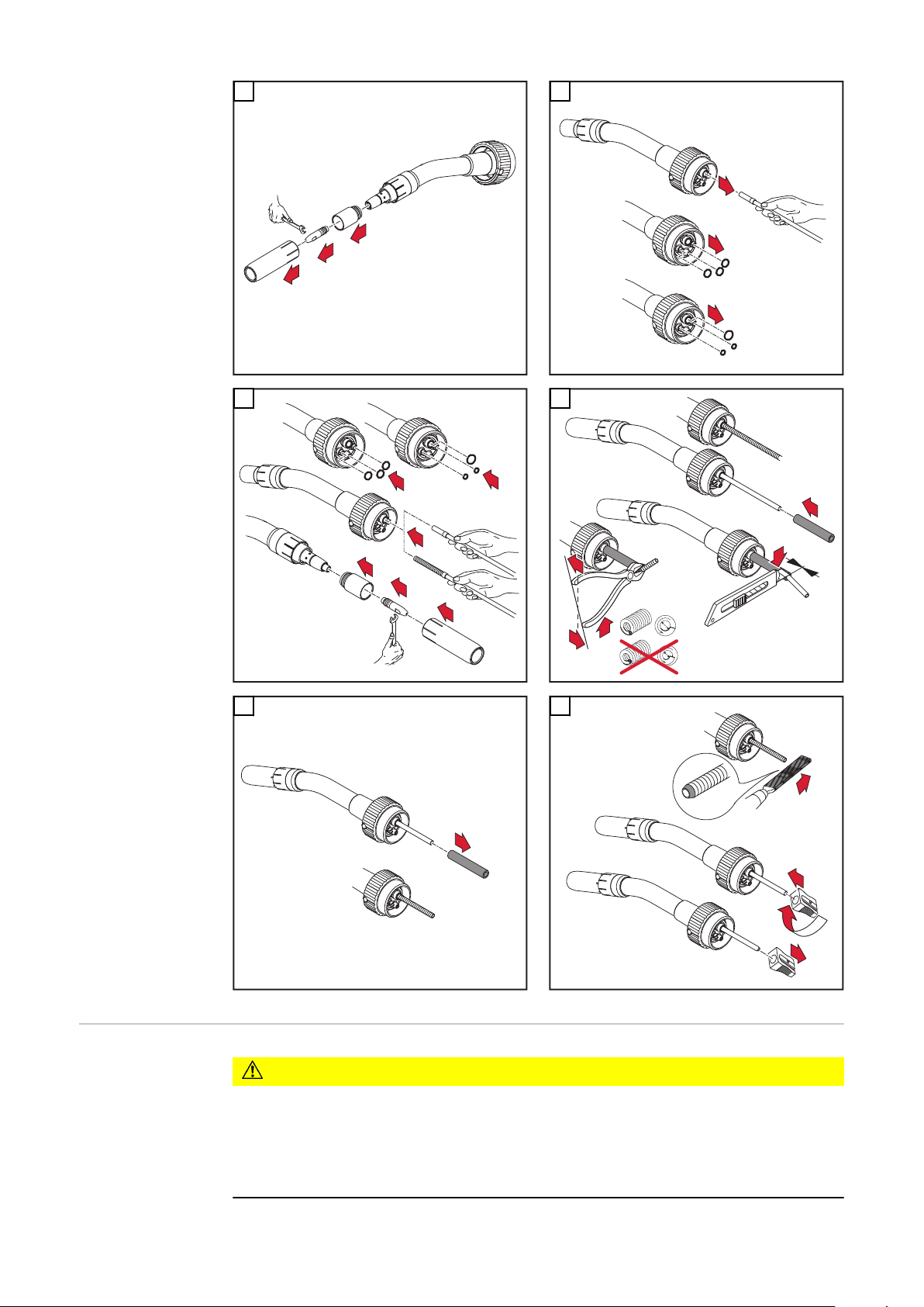
1
2
3
1
1
2
3
2
1
3
4
5
6
0 mm
.
0
inch
3
2
6
2
1
1
1
1
2
2
3
5
4
6
Robacta Drive
CMT Pro Výměna polohovací soupravy
plynových hubic
92
Nebezpečí popálení horkým hořákem.
Může dojít k vážnému zranění osob.
▶
▶
POZOR!
Před výměnou polohovací soupravy plynových hubic nechte hořák vychladnout.
Přepněte síťový vypínač zdroje do polohy „0“.

DŮLEŽITÉ! Před montáží polohovací soupravy plynových hubic musí být na
1
2
3
4
1
2
3
4
**
***
*
*
1
2
3
4
3
4
2
1
hořáku převlečná matice (*).
* Převlečná matice
Správné umístění kabelu:
** Na straně plynové hubice
*** Na straně pohonné jednotky
1
2
CS
3
4
5
93
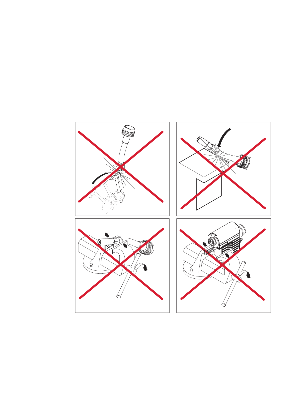
Péče, údržba a likvidace odpadu
Všeobecné informace
Pravidelná a preventivní údržba robotizovaného svařovacího hořáku CMT jsou
podstatné faktory pro zachování bezchybného provozu. Svařovací hořák je vystaven vysokým teplotám a silnému znečištění. Proto vyžaduje hořák častější
údržbu než jiné součásti svařovacího systému.
DŮLEŽITÉ! Při odstraňování rozstřiků dbejte na to, abyste neudělali na hořáku
rýhy nebo škrábance. V těchto poškozeních se mohou při dalším provozu usazovat rozstřiky.
V žádném případě neohýbejte tělo hořáku.
-
94

Při každém uve-
1
2
dení do provozu
zkontrolujte kontaktní trubici,
-
vyměňte vydřenou kontaktní trubici,
-
očistěte plynovou hubici od rozstřiků (např. ručně, vyfoukáním nebo automa-
-
tizovaně pomocí zařízení Robacta Reamer nebo Robacta TC 1000),
vyměňte hubici v případě neodstranitelného znečištění v oblasti připojení,
-
přezkoušejte těsnost vodních přípojek,
-
překontrolujte velikost zpětného toku v nádržce chladicího média, popř.
-
odvzdušněte chladicí modul.
* přezkoušejte ochranu proti strusce resp. izolaci z hlediska poškození.
CS
95

Při každé
1
2
2
1
1
2
3
2
výměně cívky
drátu
vyfoukejte bovden drátu redukovaným stlačeným vzduchem,
-
doporučujeme: vyměňte bovden drátu (min. každé 4 měsíce),
-
překontrolovat a příp. vyměnit podávací kladky,
-
vyčistit bovden drátu a poháněcí mechanismus pomocí redukovaného st-
-
lačeného vzduchu.
96

Likvidace odpadu
Plnění záruky Robotizovaný svařovací hořák CMT Robacta Drive CMT je koncipován pro auto-
Odpadní elektrická a elektronická zařízení musí být sbírána odděleně a recyklována způsobem šetrným k životnímu prostředí v souladu s evropskou směrnicí
a vnitrostátními právními předpisy. Použité spotřebiče je třeba odevzdat obchodníkovi nebo prostřednictvím místního autorizovaného systému sběru a likvidace odpadu. Správná likvidace starého přístroje podporuje udržitelnou recyklaci
materiálových zdrojů. Nedodržování předpisů může mít negativní dopad na zdraví
a životní prostředí.
Obalové materiály
Třídění odpadu. Řiďte se předpisy své obce. Stlačujte kartony, aby se zmenšil jejich objem.
matizované aplikace ve spojení s kolizním přípravkem a při běžných svařovacích
rychlostech.
Při ostatních využitích nepřebírá Fronius International GmbH žádnou záruku.
UPOZORNĚNĹ!
Uvolnění zapečetěných šroubů může vést k poškození poháněcího mechanismu.
Pokud dojde k uvolnění zapečetěných šroubů, nepřebírá Fronius International
GmbH žádnou záruku.
CS
97

Diagnostika a odstraňování závad
Diagnostika a
odstraňování
závad
Neprochází svařovací proud
Síťový vypínač zapnut, kontrolky na zdroji svítí, ochranný plyn je k dispozici
Příčina:
Odstranění:
Příčina:
Odstranění:
Příčina:
Odstranění:
Zařízení Robacta Drive CMT nepracuje
Síťový vypínač zapnut, kontrolky na zdroji svítí, ochranný plyn je k dispozici
Příčina:
Odstranění:
Příčina:
Odstranění:
Nevyhovující uzemnění
Prověření polarity uzemnění a připojení zemnicí svorky
Přerušený proudový kabel v hadicovém vedení zařízení Robacta
Drive CMT
Vyrozumění servisní služby
Volné připojení hadicového vedení
Překontrolujte správné připojení hadicového vedení
Řídící konektor nebo konektor motoru nejsou zasunuty
Správně připojte řídící konektor nebo konektor motoru
Řídící vedení nebo vedení motoru je defektní
Vyrozumění servisní služby
Příčina:
Odstranění:
Příčina:
Odstranění:
Neprotéká ochranný plyn
Všechny ostatní funkce jsou k dispozici
Příčina:
Odstranění:
Příčina:
Odstranění:
Příčina:
Odstranění:
Příčina:
Odstranění:
Poháněcí mechanismus je defektní
Vyrozumění servisní služby
Propojovací hadicové vedení je defektní nebo není správně
připojeno
Překontrolujte propojovací hadicové vedení a jeho přípojky
Prázdná lahev s ochranným plynem
Výměna lahve s ochranným plynem
Vadný magnetický plynový ventil
Výměna magnetického plynového ventilu
Poškozená či skřípnutá hadice plynu, příp. hadice chybí
Výměna, narovnání nebo montáž hadice plynu
Tělo hořáku je defektní
Výměna těla hořáku
98
Příčina:
Odstranění:
Magnetický plynový ventil v podavači CMT je defektní
Výměna magnetického plynového ventilu v podavači CMT

Nevyhovující svařovací vlastnosti
Příčina:
Odstranění:
Chybně nastavené svařovací parametry
Prověření nastavení
Příčina:
Odstranění:
Příčina:
Odstranění:
Příčina:
Odstranění:
Příčina:
Odstranění:
Příčina:
Odstranění:
Příčina:
Odstranění:
Špatné zemnicí připojení
Vytvoření dobrého kontakt se svařencem
Neprotéká žádný ochranný plyn, resp. je ho příliš málo.
Přezkoušení redukčního ventilu, hadice plynu, magnetického
ventilu plynu a přípojky plynu na hořáku U plynem chlazených
hořáků přezkoušení plynového těsnění, použití vhodného bovdenu
Přípojky netěsní
Utáhněte přípojky
nevhodná nebo poškozená kontaktní trubice
Výměna kontaktní trubice
Špatné legování drátu, resp. špatný průměr drátu
Překontrolujte vloženou cívku drátu, ověřte svařitelnost
základního materiálu
Nevhodný ochranný plyn a legování drátu
Použití vhodného ochranného plynu
CS
Příčina:
Odstranění:
Příčina:
Odstranění:
Příčina:
Odstranění:
Příčina:
Odstranění:
Příčina:
Odstranění:
Příčina:
Odstranění:
Nepříznivé svařovací podmínky: znečištění ochranného plynu
(vlhkost, vzduch), nedostatečné odstínění plynu (tavná lázeň
„vaří“, průvan), nečistoty na svařenci (rez, lak, mastnota)
Optimalizace svařovacích podmínek
znečištěná plynová hubice
Odstranění rozstřiků
Turbulence způsobené velkým množstvím ochranného plynu
Redukce množství ochranného plynu, doporučené
množství ochranného plynu (l/min) = průměr drátu (mm) x 10
(např. 16 l/min pro drátovou elektrodu o průměru 1,6 mm)
Příliš velký odstup kontaktní trubice od svařence
Zmenšete vzdálenost mezi kontaktní trubicí a svařencem (na
cca. 10-15 mm)
Příliš velký úhel náběhu hořáku
Zmenšení úhlu náběhu hořáku
Součásti zajišťující posuv drátu jsou nevhodné pro průměr
použité drátové elektrody
Použijte odpovídající součásti zajišťující posuv drátu
Příčina:
Odstranění:
Únik plynu nebo přimísení vzduchu
Překontrolujte vedení vyfoukávání a jeho ventil Překontrolujte
uzávěr vedení vyfoukávání (nátrubek)
99

Špatné podávání drátu
Příčina:
Odstranění:
Zavádění drátu nedosedá
Překontrolujte postavení zaváděcí trysky drátu vzhledem k
podávacím kladkám a opravte je
Příčina:
Odstranění:
Příčina:
Odstranění:
Příčina:
Odstranění:
Příčina:
Odstranění:
Příčina:
Odstranění:
Příčina:
Odstranění:
Příčina:
Odstranění:
Brzda na podavači drátu CMT je příliš utažena
Uvolněte nastavení brzdy na podavači drátu CMT
Otvor kontaktní trubice je zmenšen kvůli usazeninám
Výměna kontaktní trubice
Bovden drátu nebo zaváděcí nástavec drátu jsou defektní
Překontrolujte bovden drátu a zaváděcí nástavec drátu ohledně
přelomení, znečištění, atd., defektní součásti vyměňte
Nevhodné kladky pro použitou drátovou elektrodu
Použijte vhodné kladky
Špatný přítlak podávacích kladek
Překontrolujte přítlak, příp. jej znovu nastavte
Znečištěné nebo poškozené podávací kladky
Vyčištění nebo výměna podávacích kladek
Bovden drátu byl při zasouvání přelomen
Při zasouvání bovdenu se jej dotýkejte pouze v blízkosti
zaváděcí trubice
Příčina:
Odstranění:
Příčina:
Odstranění:
Příčina:
Odstranění:
Svařovací hořák je příliš horký
Příčina:
Odstranění:
Příčina:
Odstranění:
Příčina:
Odstranění:
Příliš krátký bovden po zkrácení
Výměna bovdenu a jeho zkrácení na správnou délku
Opotřebení drátové elektrody v důsledku příliš velkého přítlaku
u podávacích kladek
Zmenšení přítlaku podávacích kladek
Drátová elektroda je znečištěna nebo zarezlá
Použití vysoce jakostní drátové elektrody bez znečištění
Převlečná matice na přípojce k tělu hořáku je uvolněna
Dotáhněte převlečnou matici
Hořák byl používán déle než jaká je maximální povolená doba
Snižte výkon hořáku nebo použijte hořák výkonnější; dbejte na
maximální přípustnou dobu zapnutí a na povolené zatížení
Příliš nízký průtok chladicího média
Zkontrolujte stav chladicího média, jeho průtok, jeho znečištění,
uložení hadicového vedení atd.
100
 Loading...