

Page 1

/ Perfect Charging /Perfect Welding / Solar Energy
ROBACTA CTC Operating Instructions
Spare parts list
Contact Tip Changer
- 4,050,001 Robacta CTC ø25 M6
- 4,050,002 Robacta CTC ø25 M8x1,5
- 4,050,003 Robacta CTC ø27 M6
- 4,050,004 Robacta CTC ø27 M8x1,5
Version: 2021/05
Revision: 1.2
42,0426,0373,EN
Fronius prints on elemental chlorine free paper (ECF) sourced from certified sustainable forests (FSC).
Page 2

KYOKUTOH Europe GmbH
©
Radlkoferstraße 2
81373 München/Germany
Phone: +49-89-741185-313
Fax: +49-89-741185-315
Office Unna
Max-Planck-Straße 4
59423 Unna/Germany
Phone: +49-2303-93615-00
Fax: +49-2303-93615-29
info@kyokutoh.de
www.kyokutoh.de
Page 3

Foreword
Foreword
This operating manual contains all information pursuant to § 3 Equipment Safety Act "Conditions for
putting into circulation" (in conjunction with Machinery Directive 2006/42/EC as amended).
The operating manual is intended for persons who will be/are tasked with working on/with the
machine described here.
Only through knowledge of this operating manual can errors be avoided at the machine and fault-free
operation guaranteed. It is therefore necessary that this operating manual be known to the responsible
persons.
The operating manual is part of the user information when putting the machine on the market and
must be stored in such a way that it is accessible to the operator and the user. Should the location of
the machine change, then the operating and/or user instructions (including those provided by the
supplier) must be moved with the machine. The instructions in the operating and/or user instructions
(including those provided by the supplier) must be adhered to during all phases of product life.
Carefully read through the corresponding chapter in the operating manual before commencing work.
We accept no liability for damages and faults that arise as the result of failure to adhere to this
operating manual.
IT must be clearly and unequivocally established in-house who is responsible for the machine
(operator) and who is permitted to work at it (users).
For the staff deployed for the transport, installation, preparation, set-up, operation, care, maintenance
and repair, the corresponding responsibilities must be clearly established.
The PLUG & PLAY SETs from Tipman Co., Ltd, which belongs to the KYOKUTOH Group, are robust and
reliable complete systems for changing contact tips. They are easy and quick to integrate. Thanks to
their compact design the Contact Tip Changer can be operated intuitively. Highest quality and
durability, easy maintenance and reliable contact tip change, even under the most demanding
conditions guarantee the greatest possible economic and simplify maintenance.
Equipped with remover and fastening units for both nozzle inserts, a cutting device to shorten the
worn down welding wire, a mechanically changing magazine for ten contact tips including monitoring
sensor and a rotating cleaning unit for cleaning the contact tip.
I
Page 4

Table of Content
Table of content
1 Declaration of Conformity ............................................................................................................... 1
2 Technical Specifications ................................................................................................................... 2
2.1 Type ......................................................................................................................................... 3
2.2 Dimension ................................................................................................................................ 4
2.3 Sensor Technology .................................................................................................................. 5
3 Basic Saftey Instructions .................................................................................................................. 7
3.1 Explanation of symbols and instructions ................................................................................. 7
3.2 Proper use ............................................................................................................................... 8
3.3 Improper use ........................................................................................................................... 8
3.4 Obligation to instruct .............................................................................................................. 9
3.5 Safety devices .......................................................................................................................... 9
3.6 Systems with servo- and frequency inverters ......................................................................... 9
3.7 Inspection obligation ............................................................................................................... 9
3.8 Conduct in case of hazards and faults .................................................................................... 10
3.9 Information regarding residual risks ..................................................................................... 10
3.10 Special hazard points ............................................................................................................. 10
3.11 Safety and protection devices ............................................................................................... 10
3.12 Special safety instructions ..................................................................................................... 11
3.13 Hazards during maintenance, repair and similar work .......................................................... 12
3.14 Product monitoring ............................................................................................................... 12
4 SETUP AND ASSEMBLY .................................................................................................................. 13
4.1 Place of installation, place of use .......................................................................................... 13
4.2 Alignment and mounting ....................................................................................................... 13
4.3 Protective conductor connection on the stand..................................................................... 13
5 COMMISSIONING / SETUP ............................................................................................................. 14
5.1 Safety requirements .............................................................................................................. 14
5.2 Initial commissioning ............................................................................................................. 14
5.3 Preparation for operation ..................................................................................................... 15
5.3.1 Tolerance for centering and parallelism ....................................................................... 15
5.3.2 Process preparation for teaching .................................................................................. 16
5.3.3 Signals ............................................................................................................................ 17
5.3.4 Spacer ............................................................................................................................ 17
5.3.5 Change Spacer ............................................................................................................... 19
5.4 Teaching process ................................................................................................................... 20
II
Page 5

Table of Content
5.4.1 Preparation process....................................................................................................... 20
5.4.2 Confirmation of engine running .................................................................................... 21
5.4.3 Cut off welding wire ...................................................................................................... 22
5.4.4 Turn off and remove the nozzle .................................................................................... 24
5.4.5 Cleaning the contact tip ................................................................................................ 26
5.4.6 Actuation of the magazine (revolver) ............................................................................ 27
5.4.7 Remove contact tip ....................................................................................................... 27
5.4.8 Contact tip attachement ............................................................................................... 30
5.4.9 Attachment nozzle ......................................................................................................... 31
6 STORAGE AND TRANSPORT ........................................................................................................... 35
6.1 Safety regulations .................................................................................................................. 35
6.2 Symbols on the cargo ............................................................................................................ 35
6.3 Transport type ....................................................................................................................... 35
6.4 Handover and Inspection ...................................................................................................... 36
6.5 Unpacking and Storage .......................................................................................................... 36
7 Maintenance and Repair ............................................................................................................... 37
7.1 Maintenance.......................................................................................................................... 37
7.2 Cleaning ................................................................................................................................. 39
7.3 Repair .................................................................................................................................... 39
7.4 Safety regulations .................................................................................................................. 39
8 Decommissioning/Dismantling...................................................................................................... 41
8.1 Safety regulations .................................................................................................................. 41
8.2 Decommissioning .................................................................................................................. 41
9 SPAREPARTS .................................................................................................................................. 42
9.1 Patrlist ................................................................................................................................... 43
10 SERVICE ...................................................................................................................................... 44
10.1 Troubleshooting .................................................................................................................... 44
11 APPENDIX .................................................................................................................................. 46
11.1 Data on the different contact tips ......................................................................................... 46
11.2 Data on different nozzles ...................................................................................................... 47
11.3 Elektronic ............................................................................................................................... 48
III
Page 6

Table of Content
Rev. Description
Date
Editor
Department
Revision of chap. 5
- various corrections
05.10.2020
M. Swientek
Technology
Correction / addition chap. 9
– Ballplunger added,
05.10.2020
M. Swientek
Technology
Supplement chap. 10.1
- alarm 46 added
05.10.2020
M. Swientek
Technology
E-Plan change chap. 11.3
- Lin
05.10.2020
M. Swientek
Technology
Change chap. 2.1 Contact & Gas Nozzle
21.05.2021
G.Heimann
Technology
Change chap. 5.3.4 Fronius
item number added
t. 21.05.2021
G.Heimann
Technology
Change chap. 9.1 List of spare parts
21.05.2021
G.Heimann
Technology
Amendment Appendix E
-
Plan updated
21.05.2021
G.Heimann
Technology
1.1
1.2
corrected wire brush
e filter added, additional information added
IV
Page 7

1. Declaration of Conformity
1 Declaration of Conformity
EG-Konformitätserklärung
nach der EG-Maschinenrichtlinie 2006/42/EG
EC-Declaration of Conformity
Hiermit erklärt die
Herewith we
dass die nachfolgend bezeichneten Maschinen, aufgrund ihrer Konzeption und Bauart, soweit
in der von uns in Verkehr gebrachten Ausführung, den einschlägigen grundlegenden
Sicherheits– und Gesundheitsanforderungen der EG-Richtlinie entspricht.
Bei einer nicht mit uns abgestimmten Änderung der Maschinen, verliert diese Erklärung ihre
Gültigkeit.
declare that the machinery designated below, on the basis of its design and construction in the form brought onto the market by
us is in accordance with the relevant safety and health requirements of the EC Council Directive on Machinery.
If alterations are made to the machinery without prior consultations with us, this declaration becomes invalid
KYOKUTOH Europe GmbH
Radlkoferstraße 2
D –81373 München
Produktbezeichnung: Stromkontaktdüsen Wechsler
Designation Auto Contact Tip Changer
Maschinentyp: CTC-Serie Robacta
Machinery type CTC-Series Robacta
Einschlägige EG-Maschinenrichtlinie (2006/42/EG)
EG-Maschinenrichtlinien:
Relevant EC Council Directives
EC-Low Voltage Directive (2014/35/EU)
EC-Machinery Directive (2006/42/EG)
EG-Niederspannungsrichtlinie (2014/35/EU)
EG-Richtlinie Elektromagnetische Verträglichkeit (2014/30/EU)
EMC-Guideline (2014/30/EU)
EMV Geräteklasse: Klasse A für den Einsatz in industrieller
Umgebung
EMC – Device Class: Class A for use in an industrial environment
Hersteller-Unterschrift:
Signature
Datum: 05.09.2020
Date:
Angaben zum Unterzeichner: Johannes Okubo, Prokurist
Details signee Johannes Okubo, authorised Officer
KYOKUTOH Europe GmbH
info@kyokutoh.de
1
Page 8

2. Technical Specifications
Motor designation
BLM460SHP
-
GFV
Supply voltage
0-
240V/AC
Control voltage
24V/
DC
Power supply
connection
Without plug (cable)
Rotation sensor
Indu
c
tive
Power line 24V
Without plug (cable)
Motor Power
60 W
Torque
about
34Nm
Type of drive
electrical
Confirmation sensor
Electric motor
tips
Holder for contact
Mechanical magazine
Cleaning unit /
Wire cutter
2 Technical Specifications
CTC-001 Contact Tip Changer
Splash guard
Gearbox
Removal unit for nozzle
Removal unit for contact
tips
switch
wire brush
2
Page 9

2. Technical Specifications
Robacta CTC ø27 M6
Robacta CTC
Robacta CTC
Robacta CTC
Nozzle
Nozzle
Nozzle
Nozzle
Contact tip
Contact tip
Contact tip
Contact tip
2.1 Type
ø27 M8x1,5
ø25 M6
ø25 M8x1,5
3
Page 10

2. Technical Specifications
2.2 Dimension
4
Page 11

2. Technical Specifications
Note
!
E3T Photoelectric
E3Z photoelectric sensor /
Lower blade does
Upper
blade
Lower blade
does
2.3 Sensor Technology
Please pay attention to the correct cable connection.
sensor /
magazine query
1- E2E:
Determining the position of the cutter before cutting the welding wire in the cutting unit. (Output
signal: SS1)
not block the
insertion of the
welding wire.
The insertion into
the cutting position
is possible!
Lower
blade /
rotating
control request
block the insertion
of the welding wire.
The insertion into
the cutting position
is not possible!
Gear shaft
E2E proximity sensor /
cutter query
Proximity
sensor
5
2 x Sensor detector
Page 12

2. Technical Specifications
2- E3Z:
To check the presence of nozzle and contact tip.
To check the complete removal of nozzle and contact tip.
For checking incomplete fastening of the contact tip up to 0.5 mm with the mounting thread.
(Output signal: LS)
*For example, if the length of the thread of the contact tip is 7.0mm, the sensor determines the contact
tip from 6.5 to 7.0mm to the tip body.
3- E3T:
For checking the magazines for complete filling with contact tips. To check if the magazine cover is in
closed position. (Output signal: SS2)
6
Page 13

3. Basic Saftey Instructions
Note!
Warning: hazard point!
Warning: hazardous electrical voltage!
Warning: rotating parts
Wear eye protection
Wear gloves
Wear protective footwear
3 Basic Saftey Instructions
The health and safety of employees can only be guaranteed provided the described safety measures
are adhered to during all phases of life (construction, transport, installation etc.). Generally speaking,
the usual accident prevention regulations (Accident prevention regulations, UUV) apply, in particular the
UUV regarding safety at machines.
The operator is obliged to adhere to the valid laws and regulations, in particular in case of use outside
of the EU. This applies in particular if enhanced requirements must be implemented on account of
corresponding changes to laws and regulations.
3.1 Explanation of symbols and instructions
This symbol indicates general information for users
This symbol indicates a threatened or imminent danger to the life and health of
people. Failure to heed this warning instruction can result in material damage and
minor injuries but may also result in severe adverse health effects to lifethreatening injuries.
Failure to heed this notice may result in serious injuries or death!
Failure to heed this notice may result in serious injuries!
Appropriate eye protection must be worn. Failure to adhere to this instruction can
result in serious injuries!
Appropriate protective equipment must be worn. Failure to adhere to this
instruction can result in injuries!
Protective footwear with a steel toecap and oil-proof safety soles.
7
Page 14

3. Basic Saftey Instructions
Note!
Caution!
3.2 Proper use
The operational safety of the supplied machine is only guaranteed in case of proper
use.
This product is only for use to change specified contact tips.
Proper use also includes adherence to the operating and/or user instructions (including those provided
by the supplier) and adherence to all maintenance and service intervals.
Structural and technical changes to the machine and its accessories generally require written approval
from KYOKUTOH Europe GmbH. In case of infringements, any liability on the part of the manufacturer
and any manufacturer warranties shall become void!
No other objects (e.g. screwdrivers etc.), which are not explicitly intended for this purpose and
included within the scope of delivery, may be present in the machine (e.g. mix-ups in the parts listed
above, etc.); likewise, no non-production parts may be present around the machine. These objects can
cause damage to people and machinery. KYOKUTOH Europe GmbH accepts no liability for resulting
damage. In case of damage, liability remains with the operator and cannot be transferred to KYOKUTOH
Europe GmbH. This product should only be used for the milling of the identified electrodes.
3.3 Improper use
Warranty and liability claim in case of personal injury and material damage are
excluded if they are the result of one or more of the following causes:
– Improper installation, commissioning, operation and maintenance of the machine
– Operation of the machine while in faulty condition, without protective cover
– Installation in explosive areas
– Improper use of devices, accessories, peripherals etc.
– Operation without safety devices
– Operation with safety devices that are not in flawless condition, are short-circuited or out of
service
– Use of operating materials that are not approved by the manufacturer
– Insufficient monitoring of machine parts that are subject to wear
– Improperly performed repairs
– Emergencies caused by the impact of foreign bodies and force majeure
– Self-performed structural changes to the machine
– Self-performed changes to the
speeds, air pressure, engine speed…)
performance characteristics
(e.g. drive conditions, cylinder
8
Page 15

3. Basic Saftey Instructions
Caution!
Warning!
3.4 Obligation to instruct
The operator must instruct his employees regarding the possible risks, residual risks and the measures
to be taken in order to avoid these risks prior to the initial commissioning. This instruction must be
issued to every employee who operates the system or is in immediate proximity of these hazards.
3.5 Safety devices
The machine may only be operated if all safety devices are in functional condition.
The removal, bypassing and/or rendering ineffective of these safety devices is prohibited. The safety
devices also include the safety program contained in the software. Changes to this safety program are
prohibited.
All components of the machine, especially safety components, may only be replaced with original
components or other components subject to the written consent of KYOKUTOH Europe GmbH. In the
event that faults, and defects are identified in the safety devices, the machine must be shut down
immediately.
The safety devices must undergo the following checks prior to each time the machine is switched on,
or daily, and following every fault correction:
- Visual inspection of the safety devices, regarding the general appropriate condition and
functional safety (e.g. any bridging must be removed immediately)
- Checking of all locking systems, if present. With each check of the safety devices, it must be
ensured that no body parts or objects protrude into the hazard areas exposed by the opened
covers and that no parts can escape from the machine.
3.6 Systems with servo- and frequency inverters
We expressly point out that the integrated “Safe restart lock” does not interrupt
the power supply to the motor.
It only stops the development of a rotating field and thus safely prevents the startup of the motor. If
electrical work is carried out on the motor, then the mains power supply must be cut off using a mains
contactor or main switch. Also note the intermediate circuit discharge time of at least 5 minutes before
electrical work can be performed. LEDs switching off are no indication that the voltage supplies are
switched off and that the intermediate circuit has discharged to below 24V!
3.7 Inspection obligation
With the handover of the machine by the operator, responsibility regarding the maintenance and
inspection obligation, and in particular regarding the safety devices, is transferred to the operator of
the machine!
9
Page 16

Warning!
Warning!
3.8 Conduct in case of hazards and faults
Shut down system using EMERGENCY STOP.
Additional measures must be specified by the operator.
In the event of hazards or faults (irregularities) stop working; shut down the system and wait until it is
stationary. If there is no visual contact with the main switch, this must be secured against being
switched on again using a lock. In addition, a sign must be posted referring to the work on the system.
Correct the fault and if necessary, inform a manager / customer service / the service department.
3.9 Information regarding residual risks
Ensure the complete dissipation of residual energy.
The power supply to the control panel and ultimately to the main switch is always live.
Even when the main switch is switched off, individual components in the control cabinet may be live.
Live parts in the control cabinet and junction boxes are designed to be finger-safe, however touching
them with tools still poses the risk of contact with live parts. If work on live parts is required for
troubleshooting purposes, a second supervisor with electrical engineering training must be
brought in as an observer, in accordance with BGV A2, who will switch off the main switch and
seek help if necessary.
– Pneumatics components may drop to their starting position when the compressed air is switched
off. (Caution – residual energy!)
3.10 Special hazard points
– Entire electrical area
– Entire pneumatics area (N/A)
– Entire hydraulics area (N/A)
3.11 Safety and protection devices
– Protective doors with safety switches (safe)
– Emergency stop switch
– Main switch
10
Page 17

3. Basic Saftey Instructions
Note!
Caution!
3.12 Special safety instructions
Adhere to any user manuals for individual components that may be included in
the appendix.
Never place your hand or finger into the terminal opening while the machine is in
operation. This will result in serious injury.
This special manual is a significant component of this overall operating manual and must be observed
and adhered to. In this special manual you will find any safety instructions that protect against
potentially fatal hazards.
1. Attempt to limit contact with water as far as possible. Consequences could include operating
malfunctions (short circuit), electric shocks or short circuits.
2. Note that weld spatter does not damage the wiring. This prevents the melting of the wire
membrane and electric shock.
3. Remove any oil that accumulates on the tip dresser. Weld spatter can result in short circuits and
potential injuries.
4. Do not use any power supply other than that stated. Excessive heat can result in malfunctions and
short circuits.
5. Ensure that the power supply cable has the correct capacity. (10A/1 unit) Incorrect cabling can
result in malfunctions or short circuits.
6. Use a cable with a sufficient thickness (2 mm² or more). An incorrect cable can result in
malfunctions and short circuits.
7. Ensure that the power supply wiring is not damaged. Damaged cabling can result in malfunctions
and short circuits.
8. Secure the tip dresser firmly on the stand. If the tip dresser is not securely fixed, defective milling
operations and other problems can occur.
9. Ensure that the motor is not blocked. This could result in overheating and a potential short circuit.
10. Do not install the welding machine in the vicinity of the thermal generation source. This may result
in problems and accidents.
11. Do not install between a welding machine and a transformer. Strong magnetic forces and heat can
be dangerous and may cause malfunctions and short circuits.
11
Page 18

3. Basic Saftey Instructions
Caution!
Caution!
Note!
3.13 Hazards during maintenance, repair and similar work
Immediately after the completion of repair work, the safety devices must be
reinstalled and checked regarding their effectiveness.
All repairs and maintenance work may only be carried out if the main switch of the machine is set to
the “0” (OFF) position and locked with a padlock.
The operator is obliged to instruct the operating staff regarding the setup, effect and function of the
safety devices, as well as residual risks and conduct in accordance with occupational health & safety
regulations.
Any working step that affects the safety of the machine must be refrained from. The operator must
ensure that no unauthorized persons who have not been appropriated trained and briefed on the
requirements in the operating manual work on the machine or stay in their vicinity. Safety devices
must not be removed or placed out of service.
3.14 Product monitoring
The operator must check the machine for faults at regular intervals and analyse
the fault statistics that are compiled.
The operator must inform the manufacturer immediately of faults detected in this way, in order that
the manufacturer can correct the faults as quickly as possible.
- In the time between fault detection and the complete correction of the fault, it is the
responsibility of the operator to decide as to whether the machine
- is operated normally
- is operated with restrictions (with warning notices and instructions from the operator that are
specifically tailored to the problem in hand [cf. Equipment Usage Directive])
- is taken out of service.
In case of doubt, immediately decommission the machine
!
12
Page 19

4
. Setup and Assembly
Note!
4 SETUP AND ASSEMBLY
The machine must be set up in accordance with the planner’s installation plan.
4.1 Place of installation, place of use
Explosion areas are not permitted for this machine.
Observe the maximum load-bearing capacity of the installation area (statics).
A special foundation is not necessary.
Ensure that there is a sufficient work and traffic area!
This should be an area of at least 1m around the machine.
Connections (cables, pipes) between the systems must be laid in such a way that they do not present
a tripping hazard.
4.2 Alignment and mounting
Ensure that the machine is installed on a level, horizontal service (otherwise it may distort). All supply
connections may only be established by qualified personnel. All screws are to be tightened with the
respective tightening torques according to DIN 912.
4.3 Protective conductor connection on the stand
To fix the stand to the floor, 4 holes with Ø13mm are provided on the base plate.
13
Page 20

5. Commissioning / Setup
Caution!
Note!
Warning!
Note!
5 COMMISSIONING / SETUP
The commissioning of the machine may only be performed when wearing
suitable safety clothing.
As a rule, this machine may only be operated by authorized operating personnel,
who fulfill the requirements regarding training, briefing and qualifications.
5.1 Safety requirements
Correct faults immediately. Immediately shut down the machine in the event of
malfunctions and secure it against unintentional or unauthorized start-up.
Report any modification to the responsible body or supervisor immediately. Record all faults and
Modifikation.
5.2 Initial commissioning
Familiarize yourself with the handling and operation of the switches and controls.
Commission the machine for the first time as follows:
– Compare the specification regarding the electrical voltage supply in the control cabinet with the
available mains voltage
– Compare the specification regarding the pneumatic supply in the operating manual with the
available pneumatic system. If both details match up, then:
– Set the electrical main switch to “0” (OFF)
– Insert the mains connector into the mains socket
This process must be repeated each time you reposition the machine. This process must also be
completed if the machine has been temporarily disconnected from the supply units and then
connected to them again.
14
Page 21

5. Commissioning / Setup
5.3 Preparation for operation
Warning!
The disconnection of the electrical connection between the mains supply
and the control cabinet must be ensured.
The following steps are necessary to successfully remove and attach the nozzle and contact tip:
Before teaching:
1- Ensure that the unit is securely attached to the stand.
2- Please make sure that the I/O signals are connected to the robot or PLC.
When teaching:
1- The nozzle should be centered on the nozzle removal unit.
2- The nozzle should be aligned parallel to the unit.
3- The removal process cannot be performed due to the tilted insertion of the nozzle into the removal
unit.
4- If the above conditions are not considered, it can damage the components.
5.3.1 Tolerance for centering and parallelism
The tolerances for centering the nozzles
– Tolerance for centering the nozzle with the removal- and attaching unit (ø 1 mm)
– Tolerance for centering the contact tip with the removal unit (ø 1mm)
– Tolerance for centering the contact tip with the contact tip holder (ø 0.4mm)
The tolerance specifications for parallelism
– Tolerance between nozzle, contact tip and the removal, - attaching units (± 1 °)
15
Page 22

5. Commissioning / Setup
Tilted position of
the nozzle to the cleaning unit
Position of the nozzle parallel to the cleaning unit
5.3.2 Process preparation for teaching
1- Use the cleaning unit as a reference point / level for parallel alignment of the torch (see picture
below).
2- If the torch is parallel to the cleaning unit, move the torch horizontally to each unit.
3- Make sure that nozzle and contact tip are centered in the removal and attaching units so that
tolerances are the lowest.
16
Page 23

5. Commissioning / Setup
Output
Signals
(from
Robot
-PLC): Input
Signals
(to Robot
-
PLC):
- MC (
Magnetic Switch)
- OUT0 /
TLC (
torque control
)
Speed
setting
1 2 3 4
Caution
!
Speed [rpm]
2000 4
000 800 1000
M0 OFF ON OFF ON
M1 OFF OFF ON ON
Name:
Item number:
Verwendung:
FS-17,8L
42,0411,0350
Nozzle
Outer
- Ø 25 mm
FS-32,8L
42,0411,0352
Nozzle
Outer
- Ø 25 mm
FS-35L 42,0411,0354
Nozzle
Outer
- Ø 25
mm
FS-26,8L
42,0411,0351
Nozzle
Outer
- Ø 27 mm
FS-33,8L
42,0411,0353
Nozzle
Outer
- Ø 27 mm
Item Number
Nozzle Outer
- Ø 25 mm:
Spacer
:
42,0001,4487
FS-
17,8L
42,0001,4534
FS-
17,8L
42,0001,4902
FS-
17,8L
42,0001,4486
FS-
17,8L
42,0001,5023
FS-
17,8L
42,0001,4640
FS-
32,8L
If the robot and the contact tip changer are installed correctly on the same level (e.g. floor) and the
burner is aligned in the vertical alignment and measured as a tool in the robot controller, the
parallelism is normal.
A visual inspection of the gap dimensions can also be achieved by inserting the torch into the nozzle
removal point with a low immersion depth and complete immersion depth.
Note - WAIT commands may be necessary between the individual commands. This depends on the
programmed robot speed and how quickly the commands are processed by the robot controller. For
example, - Robot moves to a position the next command lines are already being processed during
the movement Activating the commands ahead of time can lead to problems!!!
5.3.3 Signals
Achtung: Vor dem Prozessbeginn alle Signale auf die Funktionstüchtigkeit überprüfen
- IN0 / FWD (Direction of rotation remover unit left)
- IN1 / REV (Direction of rotation remover unit right)
- IN2 / TL (Torque limiter)
- IN3 / M0 (rotation speed)
- IN4 / M1 (rotation speed)
- +24V & -0V
- OUT1 / VA (Ready)
- LS (Photoelectric barrier)
- SS1 (Proximity sensor, wire
cutter)
- SS2 (Magazine query)
- 1A (Auxiliary contact of the
magnetic connector)
When checking TLC (by hand), TL
must be switched off (OFF signal).
5.3.4 Spacer
Each CTC Fronius SET is delivered with a selection of spacers as standard. The spacer provides the right
distance to optimally remove the gas nozzle.
Depending on the used nozzle, the spacer must be installed by the customer. The table shows which
spacer is intended for which gas nozzle.
17
Page 24

5. Commissioning / Setup
42,0001,4048
FS-
32,8L
42,0001,4051
FS-
32,8L
42,0001,4474
FS-
32,8L
42,0001,4496
FS-
32,8L
42,0001,4080
FS-
32,8L
42,0001,4086
FS-
32,8L
42,0001,4497
FS-
32,8L
42,0001,4639
FS-
32,8L
42,0001,4045
FS-
32,8L
42,0001,4047
FS-
32,8L
42,0001,4475
FS-
32,8L
42,0001,4495
FS-
32,8L
42,0001,4788
FS-
32,8L
44,0350,2028
FS-
32,8L
42,0001,4085
FS-
32,8L
42,0001,4087
FS-
32,8L
42,0001,4088
FS-
32,8L
42,0001,4049
FS-
35L
42,0001,4050
FS-
35L
42,0001,4476
FS-
35L
42,0001,4494
FS-
35L
42,0001,4641
FS-
35L
44,0350,3936
FS-
35L
42,0001,4054
FS-
35L
42,0001,4043
FS-
35L
42,0001,4053
FS-
35L
42,0001,4043
FS-
35L
42,0001,4049
FS-
35L
42,0001,4050
FS-
35L
42,0001,4053
FS-
35L
42,0001,4054
FS-
35L
42,0001,4476
FS-
35L
42,0001,4494
FS-
35L
42,0001,4641
FS-
35L
44,0350,3936
FS-
35L
Item Number Nozzle Outer
- Ø 27 mm:
Spacer
:
44,0350,0222
FS-
26,8L
44,0350,2020
FS-
26,8L
44,0350,2021
FS-
26,8L
44,0350,0753
FS-
26,8L
44,0350,2004
FS-
33,8L
44,0350,1991
FS-
33,8L
44,0350,1995
FS-
33,8L
44,0350,0533
FS-
33,8L
44,0350,0752
FS-
33,8L
18
Page 25

5. Commissioning / Setup
- Remove the 4 fastening screws. Put
- Remove the entire nozzle removal
- Remove the jaws from the nozzle
- Remove the jaw guide ring.
- The spacer can now be removed.
5.3.5 Change Spacer
the cover aside.
unit.
removal unit.
The unit is reassembled in reverse
order.
19
Page 26

5. Commissioning / Setup
P
rocess
Details
5.4 Teaching process
5.4.1 Preparation process
-> Start
(Unless otherwise specified, turn all signals OFF)
-> Reset the robot signal
- Start
1
-> MC (Output): ON / (Motor drive: Power ON)
Preparation
-> after a second
(The magazine can be filled with a total of 10 contact tips. To refill, the magazine must
be turned back to its original position after changing the contact tip ten times)
The following monitoring is carried out using the SS2 photoelectric sensor:
1- The magazine is turned back to its original position
2- The complete filling of the contact tips
3- Protective cover is closed
-> SS2 Signal (Output)
-> SS2 Signal (Output) ON:
(The signal remains ON as long as the contact tips are present and remains OFF as long
as there are no contact tips)
-> True (ON) -> operational
-> continue to step (3)
from the contact nozzles
2- Confirmation of filling the magazine
-> False (OFF) -> not ready to operate
-> Stop robot
-> confirm
-> back to step (2)
20
Page 27

5. Commissioning / Setup
(Before
preforming
the change process, it must be checked that the permissible engine
5.4.2 Confirmation of engine running
load is not exceeded when idling, e.g. if foreign objects have penetrated the interior and
become noticeable, or that resistance has increased due to the wear of parts)
(Speed setting 4 = 1000rpm, Torque limit= lower than 25%
Do not perform the change process if the engine load exceeds 25%)
-> “Torque limit“ IN2 (TL) / (Input): OFF
-> “Speed setting 4“ IN3 (M0) / (Input): ON
IN4 (M1) / (Input): ON
-> “Reverse Rotation“ IN1 (REV) (Input): ON
-> (VA Signal Output: ON (When the speed signal is active)
-> TLC (Output): OFF
(Waiting for the signal: 5 Sec.)
The signal remains OFF as long as the torque limit is not exceeded.
Otherwise the signal is switched to ON.
For testing, the rotating round part can be held at the bottom at the front of the device,
in this case it is important that the TL (input) is OFF.
-> True (ON) -> “Reverse Rotation” IN1 (REV) / (Input): ON
-> “Speed setting 4“: ON
-> IN3 (M0) (Input): ON
-> IN4 (M1) (Input): ON
3- Confirmation of engine running
-> “Torque limit” IN2 (TL) / (Input): OFF
-> Continue to step (4)
-> False (OFF) -> Stop the engine
-> “Reverse Rotation” IN1 (REV) / (Input): ON
-> “Speed setting 4“: ON
-> IN3 (M0) (Input): ON
-> IN4 (M1) (Input): ON
-> “Torque limit” IN2 (TL) / (Input): ON
-> Stop robot
-> No further step possible
-> Checking the machine (CTC)
21
Page 28

5. Commissioning / Setup
5.4.3 Cut off welding wire
Requirements for cutting welding wire:
1- The welding wire must be pulled out at least 10 mm from the tip of the contact tip to
enable cutting.
2- Distance between the cutting position and the nozzle tip: 30mm
3- Rotation speed „Speed setting 1“: 2000rpm
4- Direction of rotation: (Reverse Rotation)
5- Motor “Torque limit”: Max (IN2 (TL) / (Input): ON)
-> “Torque limit” IN2 (TL) / (Input): ON
(To set the torque limit of the motor to the maximum value)
-> “Speed setting 1“: IN3 (M0) / (Input): OFF
IN4 (M1) / (Input): OFF
-> “Reverse Rotation“ IN1 (REV) / (Input): ON (Motor rotates)
-> SS1 Signal (Output): ON “Proximity sensor E2E monitors the cutter blade position”
“Reverse Rotation“ IN1 (REV) / (Input): OFF (Motor stop)
Move the welding torch and guide the electrode wire into position (2).
Query of the signals welding system ready / power source ready / wire feed unit
ready (see Fronius Interface operating instructions)
4- Cutting welding wire
-> Hold the electrode wire in place and guide it out of the nozzle
(Note: The electrode wire tip must not hit the housing surface of the cutting unit. This
can lead to a cutting error) (see right picture below)
22
Page 29

5. Commissioning / Setup
-> Guide the electrode wire to position (3)
Note - If a Fronius Wire Brake Device is installed in the welding system, it can be used to
hold the wire in place during the cutting process.
Include 2s waiting time for activation of the wire brake!
Include 3s waiting time for deactivation!
This process is not necessary because the wire cutting process works without holding the
wire electrode.
(The welding wire should be in contact at the groove at position 3)
-> “Reverse Rotation “ IN1 (REV) (Input): ON (Motor rotates)
(The cutting of the welding wire starts)
-> After approx. one second, “Reverse Rotation “ IN1 (REV) / (Input): OFF (stopping
the cutting process)
Alternative: if SS1 (Output) is OFF and then ON again, the blade has rotated through 360 °.
-> “Torque limit” IN2 (TL) / (Input): OFF
-> Wait 0,5s
-> Guide the welding torch out in reverse order (3-2-1).
-> Query of signals welding system ready / power source ready /
Wire feed unit ready
-> Pull the welding wire back into the nozzle
(Attention: Before the next step begins – “unscrewing the gas nozzle”, the wire should
be pulled back into the fastening body (see picture below).
4- Cutting welding wire
Otherwise, do not follow the steps below!
Note: If the inside diameter of the contact tip is larger than the outside diameter of the
wire, the cutting process cannot be performed without problems.
23
Page 30

5. Commissioning / Setup
Requirements for turning off
and removing the gas nozzle:
-> After inserting the gas nozzle “Forward Rotation”
IN0 (
FWD
) / (Input):
OFF
5.4.4 Turn off and remove the nozzle
1- In principle, when the nozzle is inserted into the removal unit and the unit is pressed
down, the clamping jaws extend mechanically. In this case, however, the jaws are not in
the actual clamping position. The nozzle is gripped by the clamping jaws by rotating the
removal unit REV.
2- Rotation speed “Speed setting 2“: (High Speed) 4000rpm
3- Direction of rotation of the removal unit when attaching the nozzle: (Forward Rotation)
4- Direction of rotation of the removal unit when removing the nozzle: (Reverse Rotation)
5- Engine torque: Max. (IN2 (TL) / (Input): ON
(Note: Before inserting the nozzle, check whether the jaws are retracted or pinched!)
-> “Speed setting 2“ IN3 (M0) / (Input): ON
IN4 (M1) / (Input): OFF
-> “Torque limit” IN2 (TL) / (Input): ON
-> “Forward Rotation” IN0 (FWD) / (Input): ON
-> VA Signal (Output): ON (when the speed detection signal is activated)
-> Insert the nozzle into the removal unit until the nozzle contacts the cone of the spacer.
The nozzle is not yet clamped in this position.
(Insert speed: 100cm/min od. 16mm/s)
(Pull back the jaws to easily insert the gas nozzle into the opening)
(Start changing the gas nozzle in the same time)
-> Wait 0,5s
5- Turn off and remove the nozzle
(Do not push the removal unit at the time)
24
Page 31

5. Commissioning / Setup
->
Move the torch to the stop of the spacer.
Push the nozzle
8mm
further down
.
During
this movement, the clamping jaws are extended, and the nozzle is clamped more and
more.
Spacer stop
Push 8 mm down
300cm/min or slower (48mm/s)
-> Wait 0,5s
-> “Reverse Rotation“ IN1 (REV) / (Input): ON (Motor rotates)
(Start the process of removing the nozzle)
-> Raise the welding torch after approx. 1 second
(Lifting speed: 50cm/min or 8mm/s until the nozzle is completely separated)
5- Turn off and remove the nozzle
-> After visually checking the separation of the nozzle, pull the welding torch out of the
removal unit at a speed of 416.6mm / s-10mm.
Then run the torch down at a speed of 166.6mm / s - 5mm.
Then move the burner out (the speed can be varied individually).
-> “Reverse Rotation“ IN1 (REV) / (Input): OFF (Motor stop)
-> “Speed setting 2” IN3 (M0) / (M0) (Input): OFF
-> “Torque limit” IN2 (TL) / (Input): OFF
Check the complete removal of the nozzle using LS-E and LS-R sensors).
25
Page 32

5. Commissioning / Setup
5.4.5 Cleaning the contact tip
Requirements for cleaning the contact tip:
1- Cleanability of the contact tip
2- Rotation speed “Speed setting 2“: (High Speed) 4000rpm
3- Direction of rotation of the cleaning unit when cleaning: (Reverse Rotation)
4- Engine torque: Max. (IN2 (TL) / (Input): ON)
(Note: When teaching, turning the motor REV is recommended to enable a better insertion
of the contact nozzle into the cleaning unit. Then move the welding torch up and down.)
-> “Torque limit “ IN2 (TL) / (Input): ON
-> “Speed setting 2” IN3 (M0) (Input): ON
IN4 (M1) (Input): OFF (High Speed)
-> “Reverse Rotation” IN1 (REV) / (Input): ON
-> VA Signal (Output): ON (when the speed detection signal is activated)
6- Cleaning the contact tip
Insert the contact tip into the cleaning unit.
(Insertion speed: 1m / min or 16mm / s)
When cleaning the gas holes, foreign objects are blown away with gas that is released from
the gas holes.
-> Query of signals welding system ready / power source ready /
Wire feed unit ready
-> Welding system interface signal "blow out" or "gas test" for the time of
Activate the cleaning procedure.
-> Pull out the welding torch
(Pull out speed: 700cm/min or. slower 116mm/s)
-> “Reverse Rotation “ IN1 (REV) / (Input): OFF
-> “Speed setting 2” IN3 (M0) / (Input): OFF
-> “Torque limit” IN2 (TL) / (Input): OFF
26
Page 33

5. Commissioning / Setup
5.4.6 Actuation of the magazine (revolver)
The magazine (revolver-shaped rotating unit)
(To avoid bending the welding torch, the mechanical switch should not be pressed down
more than 8mm.)
7- Actuation of the magazine (revolver)
-> Press the switch down about 7 mm
(Push down speed: 300cm/min or 48mm/s)
-> Pull out the welding torch after approx. 0.5 seconds
(Pull out speed: 2500cm/min or 417mm/s)
-> Remove the welding torch
5.4.7 Remove contact tip
1- When the contact tip removal unit rotates FWD, the clamping jaws withdraw. When
rotating REV, the clamping jaws are rotated into the clamping position and the contact
nozzle is clamped in.
2- Rotating speed: Speed setting 2 (High speed: 4000rpm)
3- Direction of rotation when retracting the jaws: FWD (forward rotation)
4- Direction of rotation when clamping the contact tip: REV (reverse rotation)
5- Engine torque: Max. (IN2 (TL) (Input): ON)
Requirements for removing the contact nozzle:
8- Remove contact tip
(Note: Before teaching and inserting the contact nozzles, check that the clamping jaws
are retracted or in the clamping position.)
-> ”Speed setting 2“ IN3 (M0) / (Input): ON
IN4 (M1) / (Input): OFF
-> “Torque limit” IN2 (TL) / (Input): ON
-> “Forward rotation” IN0 (FWD) / (Input): ON (Opening the clamping jaws)
27
Page 34

5. Commissioning / Setup
-> After about a second “Forward rotation” IN0 (FWD) / (Input): OFF
-> Stop engine
-> Insert the contact nozzle into the contact tip removal unit
(Insertion speed: 300cm/min or. slower 48mm/s)
-> Insert the contact tip so far that the clamping jaws can grip over the entire circumference.
The retaining head must not come into contact with the clamping jaws.
(This position is important for the start of the process)
(If the jaws are jammed, lower the tip of the contact nozzle towards the twist-off unit.
Then raise the welding torch by approx. 1 mm. This is the correct position for starting the
process.)
8- Remove contact tip
-> After approx. 0.5 sec. “Reverse rotation“ IN1 (REV) / (Input): ON
(Start of the removing process to remove the contact tip)
-> After a second, lift the welding torch. Set the speed as follows: (In connection with
different contact nozzles)
- M6 x 1 -> 10 cm/min (1,7mm/s)
- M8 x 1,25 -> 12,5 cm/min (2,1mm/s)
- M10 x 1,5 -> 15 cm/min (2,5mm/s)
28
Page 35
5. Commissioning / Setup
-> The direction of rotation (REV) and simultaneous lifting of the welding torch.
8- Remove contact tip
(After visual inspection that the contact nozzle has been removed.)
-> “Reverse rotation“ IN1 (REV) / (Input): OFF
(The height at which the contact nozzle is completely removed corresponds to thread
length + an excess length approx. 0.5 mm.)
(When the contact tip has been completely removed, the welding torch can be raised with
a higher speed.)
-> “Forward rotation“ IN0 (FWD) / (Input): ON
-> After approx. 0.5 sec “Forward rotation“ IN0 (FWD) / (Input): OFF
(The clamping jaws open and the used contact tip is removed as a result.)
-> “Torque limit“ IN2 (TL) / (Input): OFF
-> “Speed setting 2” IN3 (M0) / (Input): OFF
Use the LS-E and LS-R sensors to check the removal of the contact tip.
29
Page 36

5. Commissioning / Setup
Requirements
for
attaching
contact
tip:
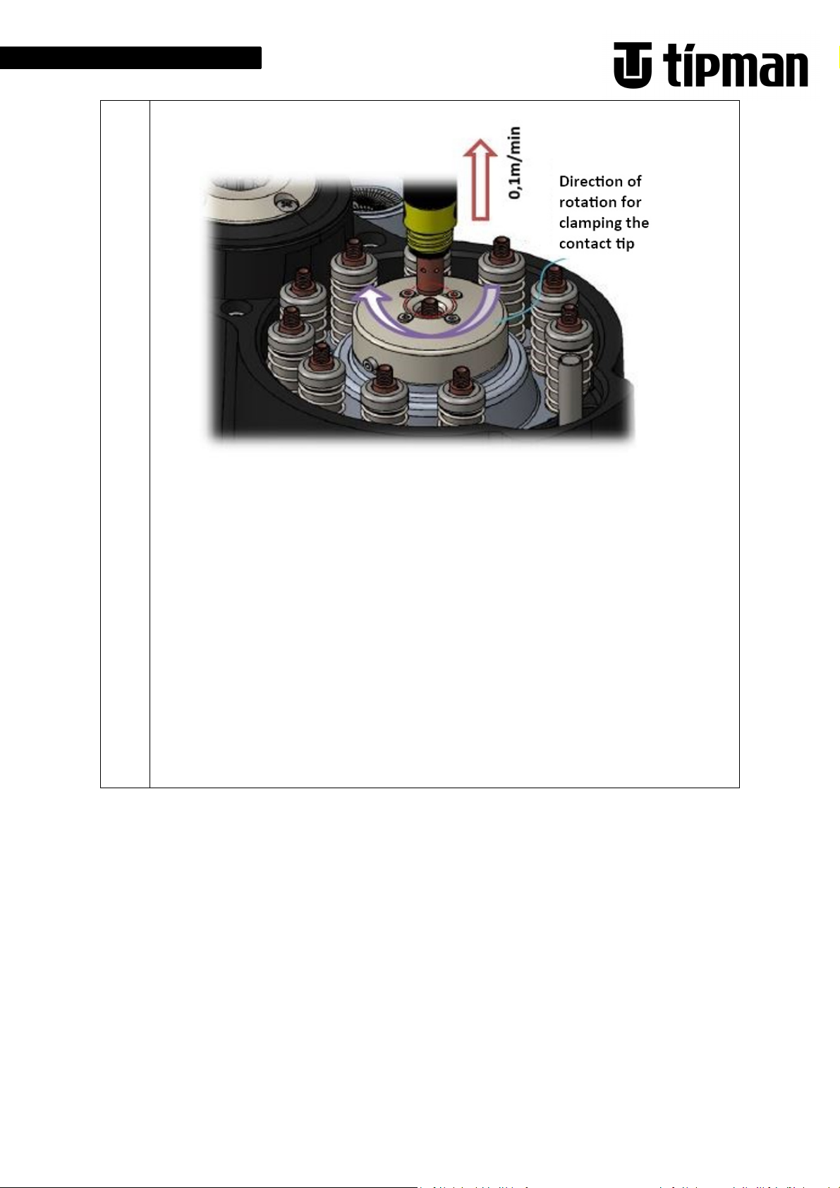
5.4.8 Contact tip attachement
1- Basically, if the contact tip holder is pressed 5 - 7 mm downwards, a connection with the
rotating unit is created.
2- Rotating speed: Speed setting 1 (Medium speed: 2000rpm)
3- Engine torque: restriction (IN2 (TL) / (Input): OFF
4- Direction of rotation of the motor when attaching contact tip: REV
-> “Torque limit“ IN2 (TL) / (Input): OFF (torque is existing)
-> “Speed setting 1“ IN3 (M0) / (Input): OFF
IN4 (M1) / (Input): OFF
-> “Reverse rotation” IN1 (REV) / (Input): ON
-> VA Signal (Output): ON (when the speed detection signal is activated)
-> Align the retaining head in the contact tip magazine
(The speed of insertion depends on the contact nozzle):
Approaching the pre-position that the retaining head of the welding torch is not yet
touching the contact tube in the contact tip magazine High approach speed
e.g. 400mm /s
Approaching the pre-position that the retaining head of the welding torch lightly touches
the contact tip in the contact tip magazine. Approach speed slightly reduced approx.
9- Contact tip attachment
200 mm /s.
Move the welding torch down another 5 mm In this position, the contact tip holder is
just not gripping the gear unit of the drive unit.
Approach speed approx. 50mm /s
Depending on the thread length of the contact tip, press the welding torch down further.
Speed depending on the thread pitch.
= Thread pitch x 10 cm/min (Thread pitch x 1.67 mm/s)
* M6 x 1 -> 10 cm/min (1,7 mm/s)
* M8 x 1,25 -> 13 cm/min (2,1 mm/s)
* M10 x 1,5 -> 15 cm/min (2,5 mm/s)
30
Page 37

5. Commissioning / Setup
Requirements for attaching the nozzle:
1-
Basically, when the clamping unit
(The distance of pushing down should correspond to the condition of the fully tightened
contact nozzle: 9-10mm)
-> TLC signal (Output): ON (With active torque detection signal)
-> Wait 0.5s
-> “Reverse rotation” IN1 (REV) / (Input): OFF
-> Wait 0.5s
-> Raise the welding torch (lifting speed: 100 cm/min or. 16mm/s)
Use the LS-E and LS-R sensors to check the contact tip.
5.4.9 Attachment nozzle
is pressed down, the nozzle is
clamped by the clamping jaws
2- Rotating speed (two stages):
Speed setting 1 (Medium speed:
2000rpm)
Speed setting 3 (Low speed: 800rpm)
3- Engine torque:
restriction (IN2 (TL) / (Input): OFF)
4- Direction of rotation of the
10- Attachment nozzle
attaching unit when fastening the
nozzle: FWD
(Note: Tightening the nozzle with the help of third-party tools or a higher rotational
speed can lead to the knurling of the nozzle being damaged or breaking the insulating
material.)
31
Page 38

5. Commissioning / Setup
-> Drive the torch down until the insulating part comes into light contact with the gas
nozzle. Caution: Do not push the unit down
(Insertion speed: 300cm / min or slower 48mm / s)
-> Drive the welding torch into the unit at a lower speed of 100 cm / min (16 mm / s)
Distance so that the nozzle is not yet pressed down by the welding torch. (Check
beforehand that the gas nozzle front edge is in contact with the inner pressure device
noticeable due to the spring-loaded bearing)
Thread welding torch small distance about 1mm or less to thread gas nozzle
32
Page 39

5. Commissioning / Setup
-> ”Torque limit“ IN2 (TL) / (Input): OFF (Torque limit available)
-> “Speed setting 1” IN3 (M0) / (Input): OFF
IN3 (M0) / (Input): OFF (Medium speed)
-> ”Forward rotation“ IN0 (FWD) / (Intput): ON
-> VA signal (Output): ON (when the speed detection signal is activated)
-> Drive the welding torch approx. 8mm deeper into the entire jaw device. Speed depending
on the thread pitch.
The inner clamping device is not yet in this position, but the jaws are extended during this
movement. (Total distance of the inner clamping device = 13mm).
The nozzle is screwed on at medium speed (2000 rpm / torque limit 45-55%).
(The speed of insertion depends on the gas nozzle):
= Thread pitch x 10 cm/min (Thread pitch x 1.67 mm/s)
* Pitch 2 -> 20 cm/min (3,3 mm/s)
* Pitch 3 -> 30 cm/min (5,0 mm/s)
* Pitch 4 -> 40 cm/min (6,6 mm/s)
10- Attachment nozzle
(The speed should be reduced to low before it is fully attached, which is the best way to
tighten the gas nozzle.)
-> “Speed setting 3” IN3 (M0) / (Input): OFF
IN4 (M1) / (Input): ON (Low speed)
-> Drive the welding torch approx. another 7mm down the device. After 5mm of the
distance, the inner clamping device is at a stop (8mm + 5mm = 13mm total distance of the
inner clamping device).
After the complete distance of 7mm has been immersed, the entire clamping device
should be sunk approx. 2-3mm from the upper edge of the housing only visible in teach
mode or only briefly recognizable if the nozzle has not yet been fully screwed on in
operational mode.
The distance when pressing down should correspond to the condition of the gas nozzle
fully tightened.
The nozzle is screwed on at a slow speed (800 rpm / Torque limit 35-45%)
33
Page 40

5. Commissioning / Setup
-> TLC signal (Output): ON (when the torque detection signal is activated)
-> ”Forward rotation“ IN0 (FWD) / (Input): OFF
-> Speed setting 3” IN4 (M1) (Input): OFF
-> Extend the torch at a speed of 200 cm/min or. (33 mm/s)
-> Check the complete intake of the nozzle using LS-E and LS-R sensors.
-> MC (Output): OFF (Motor drive: switch off)
-> End
When the alarm indicator (ARM) is lit, turn the driver off and on again until the CHARGED
11. Turn off
LED (charging indicator) switches off.
* If the steps 1-10 contain errors, carry out a teaching correction!
Notes for ongoing operations:
It is recommended to clean the thread of the nozzle and the thread on the welding torch at regular
intervals. Due to unfavorable conditions, welding spatter can penetrate this area and cause the
threads to wear prematurely.
The thread can be cleaned when refilling the contact tips.
34
Page 41

6. Storage and Transport
Caution!
Caution!
6 STORAGE AND TRANSPORT
During all transportation, lifting or moving work, all safety regulations must be adhered to. This also
includes that only tested and suitable lifting tools may be used!
Failure to heed the following instructions in the event of damage may void your
insurance cover.
6.1 Safety regulations
All power, supply and disposal connections may only be disconnected by qualified
personnel.
Only use suitable, undamaged, and fully functional transport equipment with sufficient load-bearing
capacity. Only attach transport / slinging equipment to the points intended for this purpose.
Transport the system carefully, do not lift, support or push onto/against delicate components such as
the control panel, levers, paneling etc.!
Transport preparation:
– Remove tools from the holder or spindle/magazine
– Secure moving machine parts
– Clean the machine
– Close open line ends
6.2 Symbols on the cargo
Fragile, handle
with care
This way up
Keep dry Use no hooks
Keep away
from heat
Sling here
6.3 Transport type
The machine can be moved with a pallet truck or with a forklift and transport rollers. Transport by
lorry, rail or ship:
– Screw the machine foot to the transport surface or the bottom of the box
– Securely fasten control cabinets
– Protect against humidity and corrosion
– Secure provided accessories against slipping
35
Page 42

6. Storage and Transport
Note!
Caution!
6.4 Handover and Inspection
Suitable transport equipment must be provided during handover (e.g. forklift
truck, pallet truck).
Check the packaging after delivery:
– For transport damage
– For other abnormalities
– Document identified damage immediately (sketch, digital / instant camera, description of the
damage).
– Have the damage confirmed in writing on-site by the carrier!
– Forward the corresponding documents immediately Fronius International GmbH!
6.5 Unpacking and Storage
Transport locks, transport aids and packaging should only be removed after
positioning the machine
Dispose of the packaging material in an environmentally friendly manner or re-use it!
Specific transport aids and transport locks are retained by the customer. Store these if the system is to
be moved again.
Check the system after unpacking:
– for transport damage
– for completeness (see delivery note)
– for other abnormalities
– Document identified damage immediately (sketch, digital / instant camera, description of the
damage).
– Forward the corresponding documents immediately to Fronius International GmbH!
In case of interim storage, ensure the following:
– Suitable storage area e.g. dry, clean, heated, measures taken to prevent corrosion
– Store level, horizontally (to prevent distortion)
– Check pneumatic hoses and lines for abrasion points and leaks.
36
Page 43

8. Decommissioning / Dismantling
Note!
7 Maintenance and Repair
Maintenance, repair and cleaning must be carried out by appropriately qualified
personnel (in keeping with the respective task).
7.1 Maintenance
1- Check the attachment, removal unit and nozzle holder for correct functionality
2- Check the unlocking of the contact tip removal unit for correct functionality
3- Check the plain bearings for correct functionality
4- Remove dust and dirt from the guide pins
5- Under no circumstances open the gearbox
37
Page 44

7. Maintenance and Repair
38
Page 45

7. Maintenance and Repair
Note!
Caution!
Caution!
Warning!
Warning!
7.2 Cleaning
Only clean the machine using suitable auxiliary materials.
Switch the machine off before cleaning and secure against unauthorized restart.
It goes without saying that you should clean and care for your machine regularly. How often you must
clean it depends primarily on your work and environment. If you have no visual contact with the main
switch during cleaning work, it must be secured with a lock to prevent it from being switched on again.
In addition, information signs referring to the work must be displayed on the machine.
7.3 Repair
Be sure to adhere to accident prevention regulations! Repairs may only be
performed by commissioned specialist personnel
Be sure to allow residual energy to safely dissipate.
7.4 Safety regulations
Switch the machine off prior to performing maintenance work and secure against
unauthorized restart. In addition, information signs must be displayed referring to
the work on the machine.
Work on electrical devices may only be carried out by skilled electricians, specialist in specific electronic
activities or staff with electrical engineering training.
Live parts in the control cabinet and junction boxes are designed to be finger-safe, however touching
them with tools still poses the risk of contact with live parts.
Servicing, cleaning, etc. may only be performed with the system switched off and stationary.
In case of servicing or maintenance work:
– Switch off the power supply
– Wait for the machine to come to a stop
– Safe dissipation of residual energy (e.g. pressure accumulator, electronics)
– Do not overestimate your own strength – get help or use lifting equipment if necessary, e.g. pallet
truck.
39
Page 46

7. Maintenance and Repair
– Do not clean the machine using high-pressure cleaning equipment.
– Supply parts must be maintained in accordance with manufacturer specifications.
– Maintain a clean and tidy environment during all servicing work.
– Keep traffic routes clear.
– Restore safe operating conditions once service work is complete, i.e. check e.g. that loosened
screw connections are secure, safety devices are fully mounted and functional, connections / lines
are not leaking
– All service work must adhere strictly to the described sequence.
– Only use approved auxiliary and operating materials
– Only use original replacement parts.
.
40
Page 47

8. Decommissioning / Dismantling
Caution!
Warning!
Note!
Warning!
8 Decommissioning/Dismantling
Be sure to adhere to accident prevention regulations!
Be sure to allow residual energy to safely dissipate.
8.1 Safety regulations
Decommissioning may only be performed by commissioned specialist personnel.
Switch the machine off prior to decommissioning and secure against unauthorized
restart. In addition, information signs must be displayed referring to the work on
the machine.
Work on electrical devices may only be carried out by skilled electricians, specialist in specific electronic
activities or staff with electrical engineering training
Live parts in the control cabinet and junction boxes are designed so as to be finger-safe, however
touching them with tools still poses the risk of contact with live parts.
Do not overestimate your own strength – get help or use lifting equipment if necessary, e.g. forklift
truck.
8.2 Decommissioning
Shutdown
– Switch off, disconnect power and operating material lines
– Drain liquid and pressure containers
Cleaning
– Cleaning prior to storage
Preservation
– Apply corrosion protection
– Fill tanks and containers with corrosion protection and/or anti-freeze agent
– Replace lubricant
41
Page 48

9. Spareparts
Note!
Caution!
9 SPAREPARTS
Non-original or faulty replacement parts can cause damage or machine
malfunctions.
Replacement parts may only be replaced, or repairs performed by specialist
personnel, as there is a risk of injury on account of stored residual energy.
In order that valuable production time is not lost in the event of the failure of components that are
subject to wear and to minimize downtime, we recommend that you keep a stock of replacement parts.
Purchased parts can be taken from the enclosed sets of drawings. All components of the machine,
especially safety components, may only be replaced with original components or other components
subject to the written consent of KYOKUTOH Europe GmbH. All screws are to be tightened with the
respective tightening torques according to DIN 912
42
Page 49

9. Spareparts
Robacta Model:
4,050,001
4,050,002
Item no.:
42,0411,0357
42,0411,0358
Quantity:
4 4
Treibwerk für
4,050,001
Item no.:
42,0411,0359
Quantity
: 1
Robacta Model:
4,050,001
4,050,003
Item no.:
42,0411,0355
42,0411,0356
Quantity
: 4 4
Robacta Model:
4,050,001
Item no.:
42,0411,0362
Quantity
: 1
Robacta Model:
4,050,001
Item no.:
42,0411,0360
Quantity
: 1
Ball Plunger for
Robacta
4,050,001
Item no.:
42,0411,0361
Quantity
: 4
9.1 Partlist
Sparepart list
Clamping jaws
for contact tip
Driving finger
for contact tip
holder
Clamping jaws
for the removal
and attaching
unit of the
nozzle
Cleaning unit for
contact tips
Kontaktdüsenmagazin:
4,050,003
4,050,002
4,050,003
4,050,004
4,050,002
4,050,002
4,050,003
4,050,004
4,050,004
4,050,004
Lower blade for
welding wire
cutting
guiding gas nozzle
Model:
4,050,002
4,050,003
4,050,004
4,050,002
4,050,003
4,050,004
43
Page 50

10. Service
Note!
Warning!
Caution!
Warning!
Trouble
Possible causes
Elimination
– The power supply is interrupted
– Check connection
– The nozzle is stuck between the
– Correct the position during
– The contact tip tuck between
– Correct the position during
10 SERVICE
The penetration of cooling water from the welding grippers into the transmission
housing can result in the damage of the intake gearwheel incl. the bearings in the
transmission area, depending on operating conditions.
Be sure to regularly lubricate the transmission! (See Maintenance)
There is a risk of becoming trapped or injured as a result of the movement of the
components.
All power, supply and disposal connections may only be disconnected by qualified
personnel.
Risk of injury when troubleshooting due to residual energy (e.g. in the pneumatics
system). There is the risk that the cutting edge will suddenly start moving. Never
place your fingers in the cutting area.
10.1 Troubleshooting
A rotating unit
does not rotate
The nozzle cannot be
removed
The contact tip cannot
be removed
– Alarm mode switched on
– Nozzles are stuck
– Signals for different directions of
rotation switch on
simultaneously
jaws
– The speed of rotation is not
enough
– Foreign objects in the unit
– Insufficient torque limit when
(TL) is off
– Wrong direction of rotation
the jaws
– The jaws and contact tip are not
correctly aligned
– The speed of rotation is not
enough
– Wrong direction of rotation
– Clear alarm
– Perform teaching correction
– Cancel signals
teaching
– Extend rotation time
– Clean the unit
– Torque limit signal (TL)
– Check and switch on
– Check the direction of rotation
teaching
– Compare the diameter of the
contact tips and jaws and replace
if necessary
– Extend rotation time
– Check the direction of rotation
44
Page 51

10. Service
– Welding wire was not pulled out
– Pull the Welding wire out of the
–
The nozzle is not stuck properly
– Pay
attention to the correct
The robot's shock
– -Re-teachen
– The power was
turned on again
– Turn on the power after turning
– Control position is switched OFF
– Pay attention to the correct
– The
blade
is worn
– Exchange for new blade
– The brush is worn out
– Exchange for new ones
Trouble – Possible causes – Elimination
The contact tip is not
pinched
The nozzle is not
pinched
sensor switches off
Alarm 46 displayed on
FC screen
Malfunction of the
sensors
of the contact tip attachment
– insufficient push-down distance
– Not centered
between the jaws
– Not enough time
– Foreign objects in the unit
– Not centered or positioned
vertically
– Wrong direction of rotation
when the FWD input or REV
input was being ON.
– Unsuitable time (0.2 seconds or
more)
– Damage
– Connection Error
contact tip attachment
– Reposition and re-teach
– Pay attention to the correct
position during re-teaching
position during re-teaching
– Increase times
– Clean the unit and remove foreign
objects
– Set the correct direction of
rotation
both the FWD input and REV input
OFF.
position during re-teaching
– Correct the time
– Exchange for a new sensor
– Check the connection and
eliminate the problem
Burr after cut off the
welding wire
Contact tip is not
cleaned
In the event of faults, questions or spare parts deliveries, please contact your Fronius contact person.
– The lower blade and the surface
of the wire do not touch
– Re-teach so that there is a contact
45
Page 52

11. Appendix
C
ontact tips with wrench size
Outer diameter
ØA:
Wrench size
B:
Length
C:
Thread length
D:
Distance between the tip of the thread length
C
ontact tips with
out wrench size
Outer diameter
ØA:
Length
C:
Thread length
D:
Distance
between the tip of the thread length
11 APPENDIX
11.1 Data on the different contact tips
and the flange E:
Ø7 – Ø10
6 - 9
„0“ If without flange
and the flange E1:
Ø6 und Ø8
46
Page 53

11.
Appendix
Threaded nozzle
Shape
: Straight
(S
) /
Conical
(T
) /
Stepped
(D)
Outer diameter
ØF: Ø34mm or smaller
Length
H:
Knurling length
l: 60mm
or smaler
11.2 Data on different nozzles
47
Page 54

11.
Appendix
Speed Control Motor spec
Frame Size
80 mm
Rated Output Power
60 W
Gearhead Ratio
20:1
Power Supply
AGE11513
Single Phase 200~240 VAC
Frequency (Hz)
50/60
Rated Torque (Gearhead Shaft)
3,4 Nm
Maximum Instantaneous Torque (Gearhead
7,5 Nm
Speed Control Range (Gearhead Shaft)
100~200 r/min
Multi Speed Operation
Min. 3 speeds
Input
Speed Control: Rotational Speed 1, Rotational
FWD
and
REV (DIR)
Torque Limit (TL)
Output
Torque Limit Signal [TLC]
11.3 Elektronic
Motor Specification – Speed Control Motor CTC
(Frequency converter type BLE2D60-C)
Shaft)
I/O
Dimensions for installation screws
Three Phase 200~240 VAC
Speed 2 and Rotational Speed 3
Or Rotation Signal [MOVE]
48
Page 55

11.
Appendix
49
Page 56

FRONIUS INTERNATIONAL GMBH
Froniusstraße 1, A-4643 Pettenbach, Austria E-
Mail: sales@fronius.com www.fronius.com
Under www.fronius.com/contact you will find the addresses of all Fronius
Sales & Service Partners and locations
50
 Loading...