


Operating
In
RI IO/i
structions
Bedienungsanleitung
DE
Operating Instructions
EN
Instructions de service
FR
Manual de instrucciones
ES
Návod na obsluhu
SK
Návod k obsluze
CS
42,0410,1903 011-05122022


Inhaltsverzeichnis
Allgemeines 4
Gerätekonzept 4
Lieferumfang 5
Umgebungsbedingungen 5
Installationsbestimmungen 5
Sicherheit 5
Bedienelemente, Anschlüsse und Anzeigen 7
Bedienelemente und Anschlüsse am Interface 7
Anzeigen am Interface 7
Interface installieren 9
Sicherheit 9
Interface installieren 9
Digitale Eingangssignale - Signale vom Roboter zur Stromquelle 11
Allgemeines 11
Kenngrößen 11
Verfügbare Signale 11
Working mode (Arbeitsmodus) 11
Job number (Job-Nummer) 12
Analoge Eingangssignale - Signale vom Roboter zur Stromquelle 13
Allgemeines 13
Verfügbare Signale 13
Digitale Ausgangssignale - Signale von der Stromquelle zum Roboter 14
Allgemeines 14
Spannungsversorgung der digitalen Ausgänge 14
Verfügbare Signale 14
Anwendungsbeispiele 15
Allgemeines 15
Anwendungsbeispiel Standardmodus 15
Anwendungsbeispiel OC-Modus 15
Übersicht Pin-Belegung 17
Übersicht Pin-Belegung 17
DE
3

Allgemeines
(1) (3)(2) (4) (5)
Gerätekonzept Das Interface verfügt über analoge und digitale Ein- und Ausgänge und kann so-
wohl im Standardmodus wie auch im Open-Collector-Modus (OC-Modus) betrieben werden. Das Umschalten zwischen den Modi erfolgt mittels Jumper.
Zur Verbindung des Interfaces mit der Stromquelle wird mit dem Interface ein
Kabelbaum mitgeliefert. Als Verlängerung für den Kabelbaum ist ein ein SpeedNet-Verbindungskabel verfügbar.
Zur Verbindung des Interfaces mit der Roboter-Steuerung ist ein vorgefertigter
Kabelbaum verfügbar.
Der Kabelbaum ist interface-seitig mit Molexsteckern anschlussfertig vorkonfektioniert. Roboter-seitig muss der Kabelbaum an die Anschlusstechnik der Roboter-Steuerung angepasst werden.
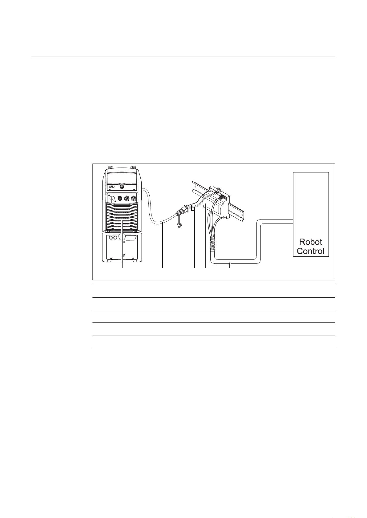
(1) Stromquelle mit optionalem Anschluss SpeedNet an der Geräterückseite
(2) SpeedNet-Verbindungskabel
(3) Kabelbaum zur Verbindung mit der Stromquelle
(4) Interface
(5) Kabelbaum zur Verbindung mit der Roboter-Steuerung
4
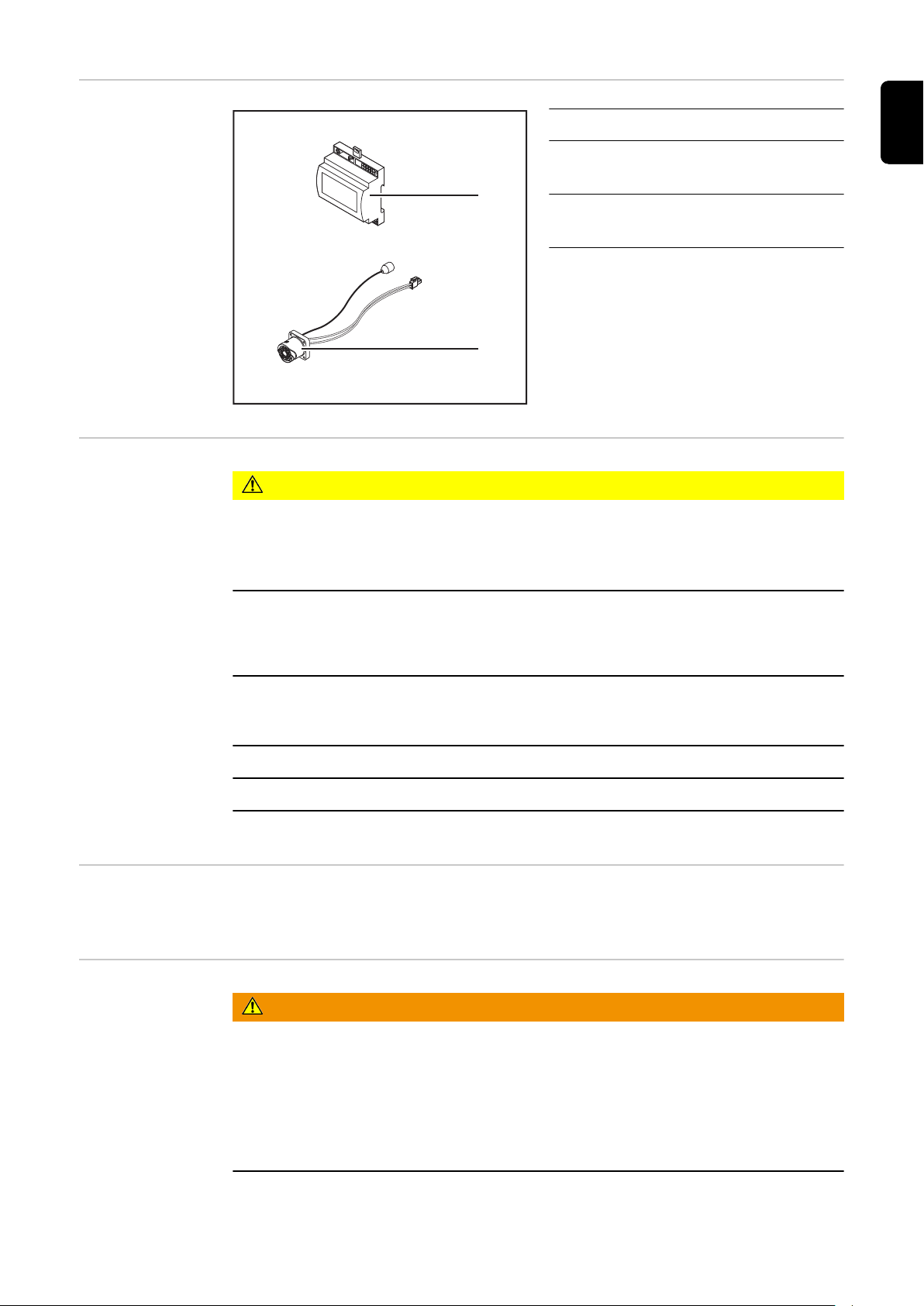
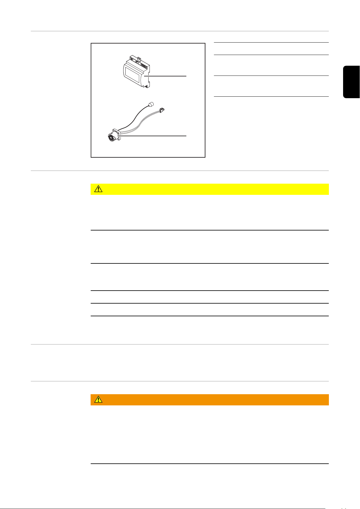
Lieferumfang
(1)
(2)
(1) Roboter-Interface
(2) Kabelbaum zur Verbindung mit
der Stromquelle
(3) Bedienungsanleitung (nicht ab-
gebildet)
DE
Umgebungsbedingungen
Installationsbestimmungen
VORSICHT!
Gefahr durch unzulässige Umgebungsbedingungen.
Schwere Geräteschäden können die Folge sein.
Das Gerät nur bei den nachfolgend angegebenen Umgebungsbedingungen
▶
lagern und betreiben.
Temperaturbereich der Umgebungsluft:
beim Betrieb: 0 °C bis + 40 °C (32 °F bis 104 °F)
-
bei Transport und Lagerung: -25 °C bis +55 °C (-13 °F bis 131 °F)
-
Relative Luftfeuchtigkeit:
bis 50 % bei 40 °C (104 °F)
-
bis 90 % bei 20 °C (68 °F)
-
Umgebungsluft: frei von Staub, Säuren, korrosiven Gasen oder Substanzen, usw.
Höhenlage über dem Meeresspiegel: bis 2000 m (6500 ft).
Das Gerät vor mechanischer Beschädigung geschützt aufbewahren/betreiben.
Das Interface muss auf einer Hutschiene in einen Automaten- oder RoboterSchaltschrank installiert werden.
Sicherheit
WARNUNG!
Gefahr durch Fehlbedienung und fehlerhaft durchgeführte Arbeiten.
Schwerwiegende Personen- und Sachschäden können die Folge sein.
Alle in diesem Dokument beschriebenen Arbeiten und Funktionen dürfen
▶
nur von geschultem Fachpersonal ausgeführt werden.
Dieses Dokument lesen und verstehen.
▶
Sämtliche Bedienungsanleitungen der Systemkomponenten, insbesondere
▶
Sicherheitsvorschriften lesen und verstehen.
5

WARNUNG!
Gefahr durch unplanmäßige Signalübertragung.
Schwerwiegende Personen- und Sachschäden können die Folge sein.
Über das Interface keine sicherheitsrelevanten Signale übertragen.
▶
6
Bedienelemente, Anschlüsse und Anzeigen
(1)(2)
(6) (5) (4) (3)
OCSTD
13149 10 1112
1 2 3 4 5 6 7
8
71110 9 8
6 5 4 3 2 1
12
5 6
1 2 3
4
2
1
OCSTD
(7)(6)(5)(4)(3)(2)(1)
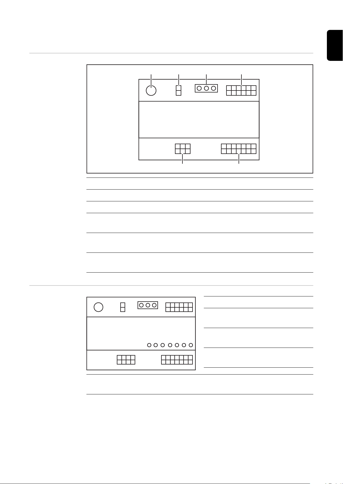
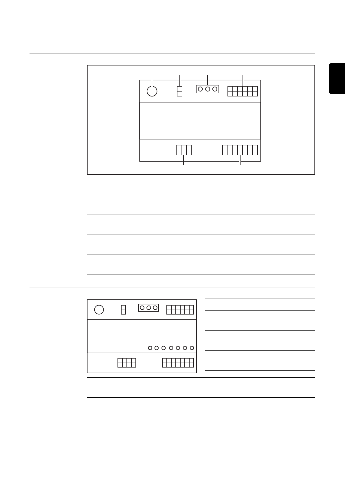
Bedienelemente
und Anschlüsse
am Interface
(1) Stecker X1
(2) Stecker X2
DE
Anzeigen am Interface
(3) Stecker X3
(4) Jumper
zum Einstellen des Betriebsmodus - Standardmodus / OC-Modus
(5) Stecker X8
zur Versorgung des Anschlusses SpeedNet
(6) Anschluss SpeedNet
zur Verbindung mit der Stromquelle
Pos. LEDAnzeige
(1) STD/OC
leuchtet, wenn OC aktiv
(2) Welding start
leuchtet, wenn aktiv
(3) Robot ready
leuchtet, wenn aktiv
(4) Touch Sensing
leuchtet, wenn aktiv
(5) Arc stable / Touch signal
leuchtet, wenn aktiv
7

(6) Power source ready
leuchtet, wenn aktiv
(7) +3V3
leuchtet, wenn die Versorgung des Interfaces gegeben ist
8
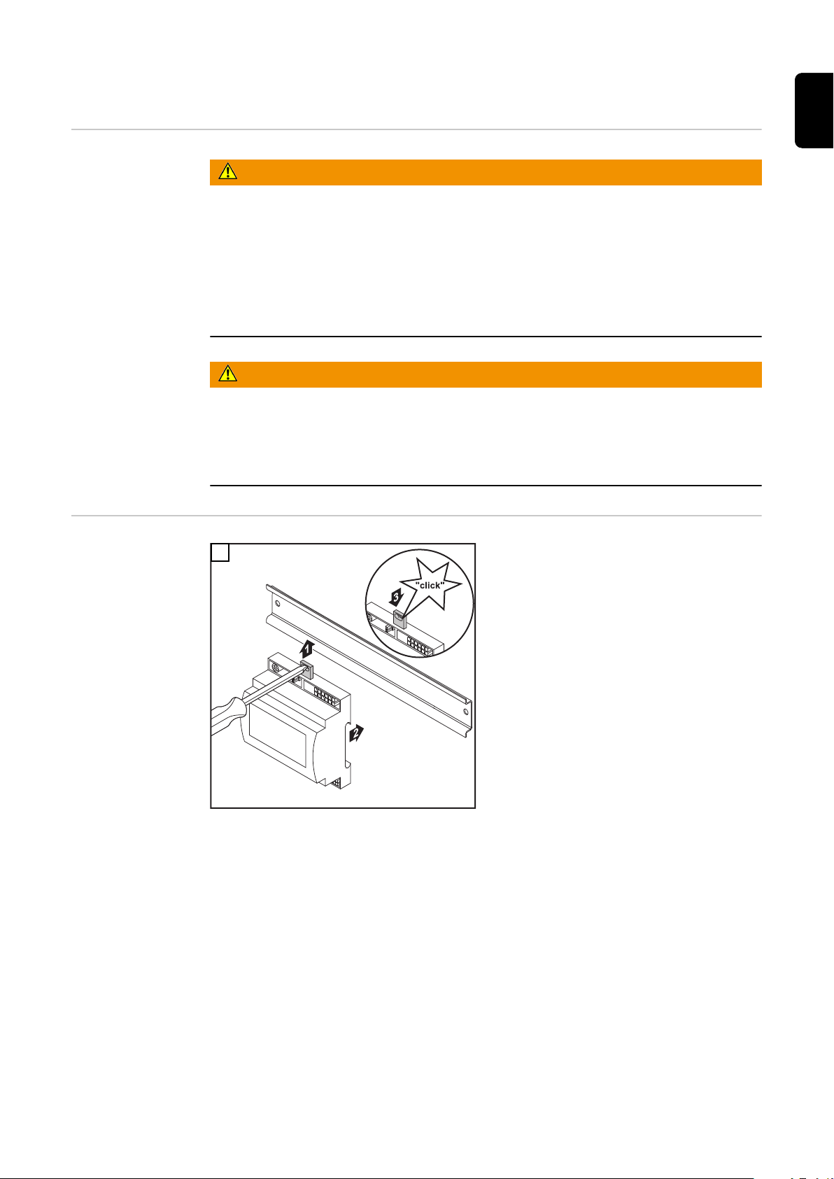
Interface installieren
DE
Sicherheit
Interface installieren
WARNUNG!
Gefahr durch elektrischen Strom.
Schwere Verletzungen und Tod können die Folge sein.
Vor Beginn der Arbeiten alle beteiligten Geräte und Komponenten ausschal-
▶
ten und von Stromnetz trennen.
Alle beteiligten Geräte und Komponenten gegen Wiedereinschalten sichern.
▶
Nach dem Öffnen des Gerätes mit Hilfe eines geeigneten Messgerätes si-
▶
cherstellen, dass elektrisch geladene Bauteile (beispielsweise Kondensatoren) entladen sind.
WARNUNG!
Gefahr durch elektrischen Strom wegen unzureichender Schutzleiter-Verbindung.
Schwerwiegende Personen- und Sachschäden können die Folge sein.
Immer die originalen Gehäuse-Schrauben in der ursprünglichen Anzahl ver-
▶
wenden.
1
9

(1)
(2)
Die Position des Jumpers am Inter-
2
face überprüfen - Standardmodus / OC-Modus
Kabelbaum (2) an die Roboter-
3
Steuerung anschließen
Kabelbaum (2) wie abgebildet an
4
das Interface anschließen
Kabelbaum (1) wie abgebildet an
5
das Interface anschließen
Kabelbaum (1) an das SpeedNet-
6
Verbindungskabel der Stromquelle
anschließen
SpeedNet-Verbindungskabel an
7
den Anschluss SpeedNet an der
Rückseite der Stromquelle anschließen
10

Digitale Eingangssignale - Signale vom Roboter
zur Stromquelle
Allgemeines Beschaltung der digitalen Eingangssignale
im Standardmodus auf 24 V (High)
-
im Open-Collector-Modus auf GND (Low)
-
HINWEIS!
Beim Open-Collector-Modus sind alle Signale invertiert (invertierte Logik).
Kenngrößen Signalpegel:
Low (0) = 0 - 2,5 V
-
High (1) = 18 - 30 V
-
Bezugspotential: GND = X1/13, X1/14, X3/4, X3/12
Verfügbare Signale
Die Beschreibungen der nachfolgenden Signale sind in dem Dokument „Signalbeschreibungen Interface TPS/i“ zu finden.
DE
Working mode
(Arbeitsmodus)
Signalbezeichnung
Belegung
Welding start (Schweißen ein)
Stecker X1/1
Robot ready (Roboter bereit)
Stecker X1/2
Wire forward (Draht vor)
Stecker X1/3
Torch blow out (Brenner ausblasen)
Stecker X15
Touch sensing (Touch sensing)
Stecker X1/4
Working mode (Arbeitsmodus) siehe nachfolgende Beschreibung des
Job number (Job-Nummer) siehe nachfolgende Beschreibung des
Wertebereich Arbeitsmodus:
Bit 2 | Bit 1 | Bit 0 Beschreibung
Beschaltung Standardmodus
Beschaltung OC-Modus
24 V = aktiv
0 V = aktiv
24 V = aktiv
0 V = aktiv
24 V = aktiv
0 V = aktiv
24 V = aktiv
0 V = aktiv
24 V = aktiv
0 V = aktiv
Signals
Signals
0 | 0 | 0 Parameteranwahl intern
0 | 0 | 1 Kennlinien Betrieb Sonder 2-Takt
0 | 1 | 0 Job Betrieb
11

HINWEIS!
Die Schweißparameter werden mittels analogen Sollwerten vorgegeben.
Signal-Level wenn Bit 0 - Bit 2 gesetzt ist:
Signal-Level im Standardmodus Signal-Level im OC-Modus
Stecker X1/7 (Bit 0) = High Stecker X1/7 (Bit 0) = Low
Stecker X1/8 (Bit 1) = High Stecker X1/8 (Bit 1) = Low
Stecker X1/9 (Bit 2) = High Stecker X1/9 (Bit 2) = Low
Job number
(Job-Nummer)
Das Signal Job number steht zur Verfügung, wenn mit den Working mode-
-
Bits 0 - 2 der Kennlinien Betrieb Sonder 2-Takt oder der Job Betrieb ausgewählt wurde.
Für nähere Informationen zu den Working mode-Bits 0 - 2 siehe
-
Working mode (Arbeitsmodus) ab Seite 11
Mit dem Signal Job number erfolgt ein Abruf gespeicherter Schweißparame-
-
ter über die Nummer des entsprechenden Jobs.
Standardmodus
Stecker
X1/10 24 V - Bit 1
X1/11 24 V - Bit 2
X1/12 24 V - Bit 3
Die gewünschte Job-Nummer ist mittels Bit-Codierung auszuwählen (0-7 mögliche Job-Nummern):
00000001 = Job-Nummer 1
-
00000010 = Job-Nummer 2
-
00000011 = Job-Nummer 3
-
...
-
00000111 = Job-Nummer 7
-
OC-Modus
0 V - Bit 1
0 V - Bit 2
0 V - Bit 3
12
HINWEIS!
Job-Nummer “0” ermöglicht eine Job-Anwahl am Bedienpanel der Stromquelle.

Analoge Eingangssignale - Signale vom Roboter
zur Stromquelle
Allgemeines Die analogen Differenzverstärker-Eingänge am Interface gewährleisten eine gal-
vanische Trennung des Interfaces von den analogen Ausgängen der RoboterSteuerung. Jeder Eingang am Interface verfügt über ein eigenes negatives Potential.
HINWEIS!
Besitzt die Roboter-Steuerung nur einen gemeinsamen GND für ihre analogen
Ausgangssignale, müssen die negativen Potentiale der Eingänge am Interface
miteinander verbunden werden.
Die nachfolgend beschriebenen analogen Eingänge sind bei Spannungen von 0 10 V aktiv. Bleiben einzelne analoge Eingänge unbelegt (beispielsweise für Arclength correction) werden die an der Stromquelle eingestellten Werte übernommen.
Verfügbare Signale
Die Beschreibungen der nachfolgenden Signale sind in dem Dokument „Signalbeschreibungen Interface TPS/i“ zu finden.
DE
Signalbezeichnung Belegung
Wire feed speed command value
(Sollwert Drahtvorschub)
Arclength correction
(Sollwert Lichtoben-Längenkorrektur)
Stecker X2/1 = 0 - 10 V
Stecker X2/4 = GND
Stecker X2/2 = 0 - 10 V
Stecker X2/5 = GND
13

Digitale Ausgangssignale - Signale von der Stromquelle zum Roboter
Allgemeines Wird die Verbindung zwischen Stromquelle und Interface unterbrochen, werden
alle digitalen Ausgangssignale am Interface auf “0” gesetzt.
Spannungsversorgung der digitalen Ausgänge
Verfügbare Signale
WARNUNG!
Gefahr durch elektrischen Strom.
Schwere Verletzungen und Tod können die Folge sein.
Vor Beginn der Arbeiten alle beteiligten Geräte und Komponenten ausschal-
▶
ten und von Stromnetz trennen.
Alle beteiligten Geräte und Komponenten gegen Wiedereinschalten sichern.
▶
Die digitalen Ausgänge müssen mit einer kundenspezifischen Spannung (bis max.
36 V) versorgt werden. Zur Versorgung der digitalen Ausgänge mit einer kundenspezifischen Spannung wie folgt vorgehen:
das Kabel der kundenspezifischen Spannungsversorgung an Stecker X3/1 an-
1
schließen
Die Beschreibungen der nachfolgenden Signale sind in dem Dokument „Signalbeschreibungen Interface TPS/i“ zu finden.
Belegung
Signalbezeichnung
Arc stable / Touch signal
(Stromfluss / Touch Signal)
Beschaltung
Stecker X3/7
24 V = aktiv
Power source ready
(Stromquelle bereit)
Collisionbox active
(Kollisionsbox aktiv)
Stecker X3/9
24 V = aktiv
Stecker X3/8
24 V = aktiv
14

Anwendungsbeispiele
X1/1
X3/7
X2/1
X2/4
X2/2
X2/5
X1/2
X3/9
X3/1
X3/8
+24 V
+24 V
+ 24 V
0 - 10 V
0 - 10 V
Robot Power source
X1/1
X3/7
X2/1
X2/4
X2/2
X2/5
X1/2
X3/9
X3/1
X3/8
+24 V
0 V
+ 0 V
Robot Power source
0 - 10 V
0 - 10 V
Allgemeines Je nach Anforderung an die Roboter-Anwendung müssen nicht alle Eingangs-
und Ausgangssignale genützt werden.
Signale welche verwendet werden müssen, sind nachfolgend mit einem Stern
markiert.
Anwendungsbeispiel Standardmodus
DE
X1/1 = Welding start (digitaler Eingang) *
X3/7 = Arc stable / Touch signal (digitaler Ausgang) *
X2/1 = Wire feed speed command value + (analoger Eingang) *
X2/4 = Wire feed speed command value - (analoger Eingang) *
X2/2 = Arclength correction + (analoger Eingang) *
X2/5 = Arclength correction - (analoger Eingang) *
X1/2 = Robot ready (digitaler Eingang) *
X3/9 = Power source ready (digitaler Ausgang)
X3/1 = Versorgungsspannung für digitale Ausgänge *
X3/8 = Collisionbox active (digitaler Ausgang)
* = Signal muss verwendet werden
Anwendungsbeispiel OC-Modus
15

X1/1 = Welding start (digitaler Eingang) *
X3/7 = Arc stable / Touch signal (digitaler Ausgang) *
X2/1 = Wire feed speed command value + (analoger Eingang) *
X2/4 = Wire feed speed command value - (analoger Eingang) *
X2/2 = Arclength correction + (analoger Eingang) *
X2/5 = Arclength correction - (analoger Eingang) *
X1/2 = Robot ready (digitaler Eingang) *
X3/9 = Power source ready (digitaler Ausgang)
X3/1 = Versorgungsspannung für digitale Ausgänge *
X3/8 = Collisionbox active (digitaler Ausgang)
* = Signal muss verwendet werden
16

Übersicht Pin-Belegung
DE
Übersicht PinBelegung
Stecker X1 - digital Input:
Pin Signal
1 Welding start
2 Robot ready
3 Wire forward
4 Touch sensing
5 Torch blow out
6 -
7 Working mode, BIT 0
8 Working mode, BIT 1
9 Working mode, BIT 2
10 Job number, BIT 0
11 Job number, BIT 1
12 Job number, BIT 2
13 GND
14 GND
Stecker X2 - analog Input:
Pin Signal
1 Wire feed speed command value
2 Arclength correction command value
3 -
4 GND Wire feed speed command value
5 GND Arclength correction command value
6 -
Stecker X3 - digital Output:
Pin Signal
1 Versorgungsspannung für digitale Ausgänge
2 -
3 -
4 GND
5 -
6 -
17

7 Arc stable
8 Collisionbox active
9 Power source ready
10 -
11 -
12 GND
18

Contents
General 20
Device concept 20
Scope of supply 21
Environmental conditions 21
Installation regulations 21
Safety 21
Control elements, connections and displays 23
Controls and connection sockets on the interface 23
Indicators on the interface 23
Install interface 25
Safety 25
Installing the interface 25
Digital input signals - signals from robot to power source 26
General 26
Parameters 26
Available signals 26
Working mode (Working mode) 26
Job number (Job number) 27
Analogue input signals - signals from robot to power source 28
General 28
Available signals 28
Digital output signals - signals from power source to robot 29
General 29
Power supply for the digital outputs 29
Available signals 29
Application examples 30
General 30
Standard mode application example 30
OC mode application example 30
Overview of pin assignment 32
Overview of pin assignment 32
EN
19
General
(1) (3)(2) (4) (5)
Device concept The interface has analogue and digital inputs and outputs and can be operated in
standard mode as well as Open Collector mode (OC mode). A jumper is used for
switching between modes.
A cable harness is supplied with the interface for connecting it to the power
source. A SpeedNet connection cable is available as an extension for the cable
harness.
A prefabricated cable harness is available for connecting the interface to the robot controller.
The prefabricated cable harness is ready to connect and is equipped with Molex
plugs at the interface end. At the robot end, the cable harness must be modified
to match the termination system used on the robot controller.
(1) Power source with optional SpeedNet connection on rear of unit
(2) SpeedNet connection cable
(3) Cable harness for connecting to the power source
(4) Interface
(5) Cable harness for connecting to the robot controller
20
Scope of supply
(1)
(2)
(1) Robot interface
(2) Cable harness for connecting
to the power source
Environmental
conditions
(3) Operating instructions (not
shown)
CAUTION!
Danger due to unacceptable environmental conditions.
This can result in severe damage to the device.
The device must only be stored and operated in the following environmental
▶
conditions.
Ambient air temperature range:
During operation: 0 °C to + 40 °C (32 °F to 104 °F)
-
During transport and storage: -25 °C to +55 °C (-13 °F to 131 °F)
-
EN
Installation regulations
Safety
Relative humidity:
Up to 50% at 40 °C (104 °F)
-
Up to 90% at 20 °C (68 °F)
-
Keep ambient air free from dust, acids, corrosive gases and substances, etc.
Can be used at altitudes of up to 2000 m (6500 ft).
The device must be stored/operated in such a way that it is protected from mechanical damage.
The interface must be installed on a DIN rail in a switch cabinet for a machine or
robot.
WARNING!
Danger due to incorrect operation and incorrectly performed work.
This can result in serious injury and damage to property.
All the work and functions described in this document must only be carried
▶
out by trained and qualified personnel.
Read and understand this document.
▶
Read and understand all the Operating Instructions for the system compon-
▶
ents, especially the safety rules.
21

WARNING!
Danger due to unplanned signal transmission.
This can result in serious injury and damage to property.
Do not transfer any safety signals via the interface.
▶
22
Control elements, connections and displays
(1)(2)
(6) (5) (4) (3)
OCSTD
13149 10 1112
1 2 3 4 5 6 7
8
71110 9 8
6 5 4 3 2 1
12
5 6
1 2 3
4
2
1
OCSTD
(7)(6)(5)(4)(3)(2)(1)
Controls and
connection sockets on the interface
(1) X1 connector
(2) X2 connector
EN
Indicators on the
interface
(3) X3 connector
(4) Jumper
for setting the operating mode - standard mode / OC mode
(5) X8 connector
for supplying the SpeedNet connection
(6) SpeedNet connection socket
for connecting to the power source
Item LEDindicator
(1) STD/OC
comes on when OC is active
(2) Welding start
lights up when active
(3) Robot ready
lights up when active
(4) Touch Sensing
lights up when active
(5) Arc stable / Touch signal
lights up when active
23

(6) Power source ready
lights up when active
(7) +3V3
comes on when the interface has a power supply
24

Install interface
(1)
(2)
Safety
Installing the interface
WARNING!
Danger from electric current.
This can result in serious injuries and death.
Before starting work, switch off all the devices and components involved and
▶
disconnect them from the grid.
Secure all the devices and components involved to prevent unintentional re-
▶
starting.
After opening the device, use a suitable measuring instrument to check that
▶
electrically charged components (such as capacitors) have been discharged.
WARNING!
Danger from electrical current due to inadequate ground conductor connection.
This can result in serious injury and damage to property.
Always use the original housing screws in the original quantity.
▶
1
EN
Check the position of the jumper
2
on the interface - standard mode /
OC mode
Connect cable harness (2) to the
3
robot control
Connect cable harness (2) to the
4
interface as illustrated
Connect cable harness (1) to the
5
interface as illustrated
Connect cable harness (1) to the
6
SpeedNet connection cable of the
power source
Connect the SpeedNet connection
7
cable to the SpeedNet connection
on the rear of the power source
25

Digital input signals - signals from robot to power
source
General Wiring of the digital input signals
in standard mode to 24 V (high)
-
in Open Collector mode to GND (low)
-
NOTE!
In Open Collector mode, all signals are inverted (inverted logic).
Parameters Signal level:
Low (0) .. 0 - 2.5 V
-
High (1) .. 18 - 30 V
-
Reference potential: GND = X1/13, X1/14, X3/4, X3/12
Available signals Descriptions of the following signals can be found in the document "Signal de-
scriptions for TPS/i interface".
Signal designation
Assignment
Welding start(Welding on)
X1/1 connector
Robot ready (Robot ready)
X1/2 connector
Wire forward (Wire forward)
X1/3 connector
Torch blow out (Welding torch gas
purging)
X15 connector
Touch sensing(TouchSensing)
X1/4 connector
Working mode(Working mode) see signal description below
Job number(Job number) see signal description below
Standard mode circuit
OC mode circuit
24 V = active
0 V = active
24 V = active
0 V = active
24 V = active
0 V = active
24 V = active
0 V = active
24 V = active
0 V = active
Working mode
(Working mode)
26
Working mode range:
Bit 2 | Bit 1 | Bit 0 Description
0 | 0 | 0 Internal parameter selection
0 | 0 | 1 Special 2-step mode characteristics
0 | 1 | 0 Job mode

NOTE!
The welding parameters are specified using analogue set values.
Signal level when bit 0 - bit 2 are set:
Job number (Job
number)
Signal level in standard mode Signal level in OC mode
Stecker X1/7 (Bit 0) = High Stecker X1/7 (Bit 0) = Low
Stecker X1/8 (Bit 1) = High Stecker X1/8 (Bit 1) = Low
Stecker X1/9 (Bit 2) = High Stecker X1/9 (Bit 2) = Low
The Job number signal is available if the special 2-step mode or Job mode
-
characteristic was selected using Working mode bits 0 - 2.
For more information on Working mode bits 0 - 2, see Working mode
-
(Working mode) from page 26.
Saved welding parameters are called up using the number of the correspon-
-
ding job by the Job number signal.
Standard mode
Connector
X1/10 24 V - bit 1
X1/11 24 V - bit 2
OC mode
0 V - bit 1
0 V - bit 2
EN
X1/12 24 V - bit 3
0 V - bit 3
The desired job number must be selected using bit coding (0-7 possible job numbers):
00000001 = job number 1
-
00000010 = job number 2
-
00000011 = job number 3
-
etc.
-
00000111 = job number 7
-
NOTE!
Job number "0" allows a job to be selected on the power source control panel.
27

Analogue input signals - signals from robot to
power source
General The analogue differential amplifier inputs on the interface ensure that the inter-
face is electrically isolated from the analogue outputs on the robot controller.
Each input on the interface has its own negative potential.
NOTE!
If the robot controller uses only a common GND for its analogue output signals,
the negative potentials, i.e. the inputs on the interface, must be linked together.
The analogue inputs described below are active at voltages of 0 - 10 V. If individual analogue inputs are not assigned (for example for Arclength correction) the
values set at the power source will be used.
Available signals Descriptions of the following signals can be found in the document "Signal de-
scriptions for TPS/i interface".
Signal designation Assignment
Wire feed speed command value
(Wire speed set value)
Arclength correction
(Arc length correction set value)
X2/1 connector = 0 - 10 V
X2/4 connector = GND
X2/2 connector = 0 - 10 V
X2/5 connector = GND
28

Digital output signals - signals from power source
to robot
General If the connection between the power source and the interface is interrupted, all
digital output signals on the interface will be set to "0".
Power supply for
the digital outputs
Danger from electric current.
This can result in serious injuries and death.
▶
▶
The digital outputs must be supplied with a customer-specific voltage (up to
max. 36 V). In order to supply the digital outputs with a customer-specific voltage, proceed as follows:
Available signals Descriptions of the following signals can be found in the document "Signal de-
scriptions for TPS/i interface".
WARNING!
Before starting work, switch off all the devices and components involved and
disconnect them from the grid.
Secure all the devices and components involved to prevent unintentional restarting.
Connect the customer-specific power supply cable to connector X3/1
1
EN
Signal designation
Arc stable / Touch signal
(Current flow / touch signal)
Power source ready
(Power source ready)
Collisionbox active
(CrashBox active)
Assignment
Circuit
X3/7 connector
24 V = active
X3/9 connector
24 V = active
X3/8 connector
24 V = active
29

Application examples
X1/1
X3/7
X2/1
X2/4
X2/2
X2/5
X1/2
X3/9
X3/1
X3/8
+24 V
+24 V
+ 24 V
0 - 10 V
0 - 10 V
Robot Power source
X1/1
X3/7
X2/1
X2/4
X2/2
X2/5
X1/2
X3/9
X3/1
X3/8
+24 V
0 V
+ 0 V
Robot Power source
0 - 10 V
0 - 10 V
General Depending on the demands placed on the robot application, not all input and
o be used.
Standard mode
applica
ample
tion ex-
output signals need t
Signals that need to be used are marked with an asterisk below.
X1/1 = Welding start (digital input) *
X3/7
X2/1 = Wire feed speed command value + (analogue input) *
X2/4 = Wire feed speed command value - (analogue input) *
X2/2 = Arclength correction + (analogue input) *
X2/5 = Arclength correction - (analogue input) *
X1/2 = Robot ready (digital input) *
X3/9 = Power source ready (digital output)
X3/1 = Supply voltage for digital outputs *
X3/8 = Collisionbox active (digital output)
* = signal must be used
OC mode appli-
tion example
ca
30
= Arc stable / Touch signal (digital output) *

X1/1 = Welding start (digital input) *
X3/7 = Arc stable / Touch signal (digital output) *
X2/1 = Wire feed speed command value + (analogue input) *
X2/4 = Wire feed speed command value - (analogue input) *
X2/2 = Arclength correction + (analogue input) *
X2/5 = Arclength correction - (analogue input) *
X1/2 = Robot ready (digital input) *
X3/9 = Power source ready (digital output)
X3/1 = Supply voltage for digital outputs *
X3/8 = Collisionbox active (digital output)
* = signal must be used
EN
31

Overview of pin assignment
Overview of pin
assignment
X1 connector - digital input:
Pin Signal
1 Welding start
2 Robot ready
3 Wire forward
4 Touch sensing
5 Torch blow out
6 -
7 Working mode, BIT 0
8 Working mode, BIT 1
9 Working mode, BIT 2
10 Job number, BIT 0
11 Job number, BIT 1
12 Job number, BIT 2
13 GND
14 GND
X2 connector - analogue input:
Pin Signal
1 Wire feed speed command value
2 Arclength correction command value
3 -
4 GND Wire feed speed command value
5 GND Arclength correction command value
6 -
X3 connector - digital output:
Pin Signal
1 Supply voltage for digital outputs
2 -
3 -
32
4 GND
5 -
6 -

7 Arc stable
8 Collisionbox active
9 Power source ready
10 -
11 -
12 GND
EN
33

34

Sommaire
Généralités 36
Concept d'appareil 36
Contenu de la livraison 37
Conditions environnementales 37
Consignes d'installation 37
Sécurité 37
Éléments de commande, raccords et voyants 39
Éléments de commande et connecteurs de l'interface 39
Indications sur l'interface 39
Installer l'interface 41
Sécurité 41
Installer l'interface 41
Signaux d'entrée numériques – Signaux du robot vers la source de courant 43
Généralités 43
Grandeurs caractéristiques 43
Signaux disponibles 43
Working mode (Mode travail) 43
Job number (Numéro de job) 44
Signaux d'entrée analogiques – Signaux du robot vers la source de courant 45
Généralités 45
Signaux disponibles 45
Signaux de sortie numériques – Signaux de la source de courant vers le robot 46
Généralités 46
Tension d'alimentation des sorties numériques 46
Signaux disponibles 46
Exemples d'utilisation 47
Généralités 47
Exemple d'utilisation – mode standard 47
Exemple d'utilisation – mode OC 47
Vue d'ensemble de l'affectation des broches 49
Vue d'ensemble de l'affectation des broches 49
FR
35

Généralités
(1) (3)(2) (4) (5)
Concept d'appareil
L'interface dispose d'entrées et de sorties analogiques et numériques, et peut
donc fonctionner aussi bien en mode standard qu'en mode Open-Collector (mode OC). Un cavalier permet de basculer d'un mode à l'autre.
Un faisceau de câbles est livré avec l'interface et permet de connecter cette dernière à la source de courant. Un câble de raccordement SpeedNet est également
fourni pour servir de rallonge au faisceau de câbles.
Un faisceau de câbles préfabriqué est fourni pour connecter l'interface à la commande robot.
Ce faisceau de câbles est pourvu, côté interface, de fiches Molex prêtes à connecter. Côté robot, le faisceau de câbles doit être adapté à la technique de connexion de la commande robot.
(1) Source de courant avec connecteur SpeedNet en option sur la face ar-
rière de l'appareil
(2) Câble de raccordement SpeedNet
(3) Faisceau de câbles pour la connexion avec la source de courant
(4) Interface
(5) Faisceau de câbles pour la connexion avec la commande robot
36

Contenu de la li-
(1)
(2)
vraison
(1) Interface robot
(2) Faisceau de câbles pour la con-
nexion avec la source de courant
(3) Instructions de service (non
représentées)
FR
Conditions environnementales
ATTENTION!
Danger en cas de conditions environnementales non autorisées.
Cela peut entraîner de graves dommages matériels.
Stocker et utiliser l'appareil uniquement dans les conditions environnemen-
▶
tales indiquées ci-après.
Plage de température pour l'air ambiant :
lors du fonctionnement : 0 °C à +40 °C (32 °F à 104 °F)
-
lors du transport et du stockage : -25 °C à +55 °C (-13 °F à 131 °F)
-
Humidité relative de l'air :
jusqu'à 50 % à 40 °C (104 °F)
-
jusqu'à 90 % à 20 °C (68 °F)
-
Air ambiant : absence de poussières, acides, substances ou dégagements gazeux
corrosifs, etc.
Altitude au-dessus du niveau de la mer : jusqu'à 2 000 m (6500 ft).
Conserver et faire fonctionner l'appareil à l'abri de toute source éventuelle d'endommagements d'origine mécanique.
Consignes d'installation
Sécurité
L'interface doit être installée sur un profilé chapeau dans une armoire de commande pour automate ou robot.
AVERTISSEMENT!
Danger en cas d'erreur de manipulation et d'erreur en cours d'opération.
Cela peut entraîner des dommages corporels et matériels graves.
Toutes les fonctions et tous les travaux décrits dans le présent document
▶
doivent uniquement être exécutés par du personnel qualifié.
Le présent document doit être lu et compris.
▶
Toutes les instructions de service des composants périphériques, en particu-
▶
lier les consignes de sécurité, doivent être lues et comprises.
37

AVERTISSEMENT!
Danger en cas de transmission de signal imprévue.
Cela peut entraîner des dommages corporels et matériels graves.
Ne pas transmettre de signaux relatifs à la sécurité via l'interface.
▶
38

Éléments de commande, raccords et voyants
(1)(2)
(6) (5) (4) (3)
OCSTD
13149 10 1112
1 2 3 4 5 6 7
8
71110 9 8
6 5 4 3 2 1
12
5 6
1 2 3
4
2
1
OCSTD
(7)(6)(5)(4)(3)(2)(1)
Éléments de
commande et
connecteurs de
l'interface
(1) Prise X1
(2) Prise X2
FR
Indications sur
l'interface
(3) Prise X3
(4) Cavalier
pour le réglage du mode de service – mode standard / mode OC
(5) Prise X8
pour l'alimentation du connecteur SpeedNet
(6) Connecteur SpeedNet
pour la connexion avec la source de courant
Pos. VoyantLED
(1) STD/OC
s'allume lorsque le mode OC
est actif
(2) Welding start
s'allume lorsque la fonction est
active
(3) Robot ready
s'allume lorsque la fonction est
active
(4) Touch Sensing
s'allume lorsque la fonction est active
(5) Arc stable / Touch signal
s'allume lorsque la fonction est active
39

(6) Power source ready
s'allume lorsque la fonction est active
(7) +3V3
s'allume lorsque l'interface est alimentée
40

Installer l'interface
Sécurité
Installer l'interface
AVERTISSEMENT!
Risque d'électrocution.
Cela peut entraîner la mort et des blessures graves.
Avant d'entamer les travaux, déconnecter tous les appareils et composants
▶
concernés et les débrancher du réseau électrique.
S'assurer que tous les appareils et composants concernés ne peuvent pas
▶
être reconnectés.
Après ouverture de l'appareil, s'assurer, à l'aide d'un appareil de mesure ap-
▶
proprié, que les composants à charge électrique (condensateurs, par ex.)
sont déchargés.
AVERTISSEMENT!
Risque d'électrocution en cas de connexion de conducteur de terre insuffisante.
Cela peut entraîner des dommages corporels et matériels graves.
Toujours utiliser le nombre initial de vis originales du boîtier.
▶
1
FR
41

(1)
(2)
Contrôler la position du cavalier au
2
niveau de l'interface – mode standard / mode OC
Raccorder le faisceau de câbles (2)
3
à la commande robot
Raccorder le faisceau de câbles (2)
4
à l'interface, comme illustré
Raccorder le faisceau de câbles (1)
5
à l'interface, comme illustré
Raccorder le faisceau de câbles (1)
6
au câble de raccordement SpeedNet de la source de courant
Raccorder le câble de raccorde-
7
ment SpeedNet au connecteur
SpeedNet situé sur la face arrière
de la source de courant
42

Signaux d'entrée numériques – Signaux du robot
vers la source de courant
Généralités Connexion des signaux d'entrée numériques
en mode standard à 24 V (High)
-
en mode Open-Collector sur GND (Low)
-
Grandeurs caractéristiques
Signaux disponibles
REMARQUE!
En mode Open-Collector, tous les signaux sont inversés (logique inversée).
Niveau des signaux :
Low (0) = 0 - 2,5 V
-
High (1) = 18 - 30 V
-
Potentiel de référence : GND = X1/13, X1/14, X3/4, X3/12
Les descriptions des signaux suivants figurent dans le document « Descriptions
des signaux de l'interface TPS/i ».
Désignation du signal
Affectation
Welding start (Début du soudage)
prise X1/1
Robot ready (Robot prêt)
prise X1/2
Connexion mode standard
Connexion mode OC
24 V = actif
0 V = actif
24 V = actif
0 V = actif
FR
Working mode
(Mode travail)
Wire forward (Avance du fil)
prise X1/3
Torch blow out (Soufflage de la tor-
che de soudage)
prise X15
Touch sensing (Détection par contact)
prise X1/4
Working mode (Mode travail) voir description du signal ci-après
Job number (Numéro de job) voir description du signal ci-après
Plage de valeurs du mode travail :
Bit 2 | bit 1 | bit 0 Description
0 | 0 | 0 Sélection interne de paramètres
0 | 0 | 1 Caractéristiques mode spécial
0 | 1 | 0 Mode Job
24 V = actif
0 V = actif
24 V = actif
0 V = actif
24 V = actif
0 V = actif
2 temps
43

REMARQUE!
Les paramètres de soudage sont prédéfinis au moyen de valeurs de consigne
analogiques.
Niveau de signal quand les bits de 0 à 2 sont émis :
Niveau de signal en mode standard Niveau de signal en mode OC
Stecker X1/7 (Bit 0) = High Stecker X1/7 (Bit 0) = Low
Stecker X1/8 (Bit 1) = High Stecker X1/8 (Bit 1) = Low
Stecker X1/9 (Bit 2) = High Stecker X1/9 (Bit 2) = Low
Job number
(Numéro de job)
Le signal Job number est disponible lorsque les bits 0 à 2 des caractéristi-
-
ques de mode spécial 2 temps ou du mode job sont sélectionnés en Working
mode.
Pour plus d'informations concernant les bits 0 à 2 du Working mode voir
-
Working mode (Mode travail) à partir de la page 43
Le signal Job number permet d'appeler des paramètres de soudage enregis-
-
trés au moyen du numéro du job correspondant.
Mode standard
Prise
X1/10 24 V - bit 1
X1/11 24 V - bit 2
X1/12 24 V - bit 3
Le numéro de job souhaité doit être sélectionné au moyen d'un codage binaire (0
à 7 possibilités de numéros de job) :
00000001 = Numéro de job 1
-
00000010 = Numéro de job 2
-
00000011 = Numéro de job 3
-
...
-
00000111 = Numéro de job 7
-
Mode OC
0 V - bit 1
0 V - bit 2
0 V - bit 3
44
REMARQUE!
Le numéro de job « 0 » permet de sélectionner un job sur le panneau de commande de la source de courant.

Signaux d'entrée analogiques – Signaux du robot
vers la source de courant
Généralités Les entrées d'amplificateur différenciateur analogiques sur l'interface garantis-
sent une séparation galvanique de l'interface des sorties analogiques de la commande robot. Chaque entrée sur l'interface dispose d'un potentiel négatif qui lui
est propre.
Signaux disponibles
REMARQUE!
Si la commande robot présente seulement un GND commun pour ses signaux de
sortie analogiques, les potentiels négatifs des entrées sur l'interface doivent
être reliés entre eux.
Les entrées analogiques décrites ci-dessous sont actives à des tensions de 0 à
10 V. Si certaines entrées analogiques restent inoccupées (par exemple pour Arclength correction), les valeurs paramétrées au niveau de la source de courant
sont reprises.
Les descriptions des signaux suivants figurent dans le document « Descriptions
des signaux de l'interface TPS/i ».
Désignation du signal Affectation
Wire feed speed command value
(Valeur de consigne de la vitesse
d'avance du fil)
Arclength correction
(Valeur de consigne de la correction
de la longueur de l'arc électrique)
Prise X2/1 = 0 à 10 V
Prise X2/4 = GND
Prise X2/2 = 0 à 10 V
Prise X2/5 = GND
FR
45

Signaux de sortie numériques – Signaux de la
source de courant vers le robot
Généralités Si le raccordement entre la source de courant et l'interface est rompu, tous les
signaux de sortie numériques sur l'interface robot sont sur « 0 ».
Tension d'alimentation des
sorties numériques
Signaux disponibles
AVERTISSEMENT!
Risque d'électrocution.
Cela peut entraîner la mort et des blessures graves.
Avant d'entamer les travaux, déconnecter tous les appareils et composants
▶
concernés et les débrancher du réseau électrique.
S'assurer que tous les appareils et composants concernés ne peuvent pas
▶
être reconnectés.
Les sorties numériques doivent être alimentées par une tension spécifiques au
client (jusqu'à max. 36 V). Pour alimenter les sorties numériques avec une tension
spécifique au client, procéder comme suit :
Raccorder le câble d'alimentation de la tension spécifique au client à la pri-
1
se X3/1
Les descriptions des signaux suivants figurent dans le document « Descriptions
des signaux de l'interface TPS/i ».
Affectation
Désignation du signal
Arc stable / Touch signal
(Arc électrique stable/Signal Touch)
Connexion
Prise X3/7
24 V = actif
Power source ready
(Source de courant prête)
Collisionbox active
(CrashBox activée)
Prise X3/9
24 V = actif
Prise X3/8
24 V = actif
46

Exemples d'utilisation
X1/1
X3/7
X2/1
X2/4
X2/2
X2/5
X1/2
X3/9
X3/1
X3/8
+24 V
+24 V
+ 24 V
0 - 10 V
0 - 10 V
Robot Power source
X1/1
X3/7
X2/1
X2/4
X2/2
X2/5
X1/2
X3/9
X3/1
X3/8
+24 V
0 V
+ 0 V
Robot Power source
0 - 10 V
0 - 10 V
Généralités En fonction des exigences d'utilisation du robot, certains signaux d'entrée et de
sortie peuvent ne pas être utilisés.
Les signaux devant être utilisés sont signalés ci-après par un astérisque.
Exemple d'utilisation – mode
standard
FR
X1/1 = Welding start (Entrée numérique) *
X3/7 = Arc stable / Touch signal (Sortie numérique) *
X2/1 = Wire feed speed command value + (Entrée analogique) *
X2/4 = Wire feed speed command value - (Entrée analogique) *
X2/2 = Arclength correction + (Entrée analogique) *
X2/5 = Arclength correction - (Entrée analogique) *
X1/2 = Robot ready (Entrée numérique) *
X3/9 = Power source ready (Sortie numérique)
X3/1 = Tension d'alimentation pour sorties numériques *
X3/8 = Collisionbox active (Sortie numérique)
* = le signal doit être utilisé
Exemple d'utilisation – mode
OC
47

X1/1 = Welding start (Entrée numérique) *
X3/7 = Arc stable / Touch signal (Sortie numérique) *
X2/1 = Wire feed speed command value + (Entrée analogique) *
X2/4 = Wire feed speed command value - (Entrée analogique) *
X2/2 = Arclength correction + (Entrée analogique) *
X2/5 = Arclength correction - (Entrée analogique) *
X1/2 = Robot ready (Entrée numérique) *
X3/9 = Power source ready (Sortie numérique)
X3/1 = Tension d'alimentation pour sorties numériques *
X3/8 = Collisionbox active (Sortie numérique)
* = le signal doit être utilisé
48

Vue d'ensemble de l'affectation des broches
Vue d'ensemble
de l'affectation
des broches
Prise X1 - entrée numérique :
Pin Signal
1 Welding start
2 Robot ready
3 Wire forward
4 Touch sensing
5 Torch blow out
6 -
7 Working mode, BIT 0
8 Working mode, BIT 1
9 Working mode, BIT 2
10 Job number, BIT 0
11 Job number, BIT 1
12 Job number, BIT 2
13 GND
FR
14 GND
Prise X2 - entrée analogique :
Pin Signal
1 Wire feed speed command value
2 Arclength correction command value
3 -
4 GND Wire feed speed command value
5 GND Arclength correction command value
6 -
Prise X3 - sortie numérique :
Pin Signal
1 Tension d'alimentation pour les sorties numériques
2 -
3 -
4 GND
5 -
6 -
49

7 Arc stable
8 Collisionbox active
9 Power source ready
10 -
11 -
12 GND
50

Tabla de contenido
Generalidades 52
Concepto del sistema 52
Volumen de suministro 53
Condiciones ambientales 53
Disposiciones de instalación 53
Seguridad 54
Elementos de manejo, conexiones e indicaciones 55
Elementos de manejo y conexiones en el interface 55
Indicaciones en la interface 55
Instalación del interface 57
Seguridad 57
Instalación de interface 57
Señales de entrada digitales - Señales del robot a la fuente de corriente 59
General 59
Magnitudes características 59
Señales disponibles 59
Working mode (modo de trabajo) 59
Job number (número de Job) 60
Señales analógicas de entrada - Señales del robot a la fuente de corriente 61
General 61
Señales disponibles 61
Señales de salida digitales - Señales de la fuente de corriente al robot 62
General 62
Alimentación de tensión de las salidas digitales 62
Señales disponibles 62
Ejemplos de aplicación 63
Generalidades 63
Ejemplo de aplicación con el modo estándar 63
Ejemplo de aplicación del modo OC 63
Sinopsis de la ocupación de pines 65
Sinopsis de la ocupación de pines 65
ES
51

Generalidades
(1) (3)(2) (4) (5)
Concepto del
sistema
El interface dispone de entradas y salidas analógicas y digitales y puede ser utilizado tanto en el modo estándar como también en el modo de Open Collector
(modo OC). Los cambios entre los modos se realizan por medio del puente.
Junto al interface se suministra el cableado para conectar el interface con la fuente de corriente. Hay disponible un cable de conexión de SpeedNet como extensión del cableado.
Para conectar el interface con el control del robot se dispone del cableado prefabricado.
El cableado está preconfeccionado en el lado del interface con clavijas Molex y
está listo para la conexión. En el lado del robot es necesario adaptar el cableado
a la técnica de conexión del control del robot.
(1) Fuente de corriente con conexión opcional de SpeedNet en el lado poste-
rior del equipo
(2) Cable de conexión de SpeedNet
(3) Cableado para la conexión con la fuente de corriente
(4) Interface
(5) Cableado para la conexión con el control del robot
52

Volumen de su-
(1)
(2)
ministro
(1) Interface de robot
(2) Mazo de cables para la con-
exión con la fuente de corriente
(3) Manual de instrucciones (sin
representar)
ES
Condiciones ambientales
¡PRECAUCIÓN!
Peligro originado por unas condiciones ambientales inadmisibles.
Pueden producirse daños serios en el dispositivo.
Almacenar y utilizar el equipo solamente en las condiciones ambientales in-
▶
dicadas a continuación.
Gama de temperaturas del aire ambiental:
En servicio: 0 °C hasta + 40 °C (32 °F hasta 104 °F)
-
Durante el transporte y el almacenamiento: Entre -25 °C y +55 °C (entre -13
-
°F y 131 °F)
Humedad relativa del aire:
Hasta el 50 % a 40 °C (104 °F)
-
Hasta el 90 % a 20 °C (68 °F)
-
Aire ambiental: libre de polvo, ácidos, gases corrosivos o sustancias corrosivas,
etc.
Altura por encima del nivel del mar: hasta 2000 m (6500 ft).
Guardar/utilizar el equipo protegido frente a cualquier daño mecánico.
Disposiciones de
instalación
El interface debe instalarse sobre un carril DIN en un armario eléctrico de
autómata o de robot.
53

Seguridad
¡PELIGRO!
Peligro originado por un manejo incorrecto y trabajos realizados incorrectamente.
Esto puede ocasionar lesiones personales graves y daños materiales.
Todos los trabajos y funciones descritos en este documento deben ser realiz-
▶
ados solo por personal técnico formado.
Leer y entender este documento.
▶
Leer y entender todos los manuales de instrucciones de los componentes del
▶
sistema, en particular las normas de seguridad.
¡PELIGRO!
Peligro originado por una transmisión no prevista de la señal.
Esto puede ocasionar lesiones personales graves y daños materiales.
No transmitir señales relevantes para la seguridad a través del interface.
▶
54

Elementos de manejo, conexiones e indicaciones
(1)(2)
(6) (5) (4) (3)
OCSTD
13149 10 1112
1 2 3 4 5 6 7
8
71110 9 8
6 5 4 3 2 1
12
5 6
1 2 3
4
2
1
OCSTD
(7)(6)(5)(4)(3)(2)(1)
Elementos de
manejo y conexiones en el interface
(1) Conector X1
(2) Conector X2
ES
Indicaciones en
la interface
(3) Conector X3
(4) Puente
Para ajustar el modo de operación: modo estándar / modo OC
(5) Conector X8
Para la alimentación de la conexión de SpeedNet
(6) Conexión de SpeedNet
Para la conexión con la fuente de corriente
Pos. IndicaciónLED
(1) STD/OC
Se ilumina cuando OC está activo
(2) Welding start
Se ilumina cuando se encuentra
activo
(3) Robot ready
Se ilumina cuando se encuentra
activo
(4) Touch Sensing
Se ilumina cuando se encuentra activo
(5) Arc stable / Touch signal
Se ilumina cuando se encuentra activo
55

(6) Power source ready
Se ilumina cuando se encuentra activo
(7) +3V3
Se ilumina cuando la alimentación del interface está establecida
56

Instalación del interface
Seguridad
Instalación de
interface
¡PELIGRO!
Peligro originado por corriente eléctrica.
Pueden producirse lesiones graves y la muerte.
Antes de empezar con los trabajos, desconecte todos los dispositivos y com-
▶
ponentes implicados y desenchúfelos de la red de corriente.
Asegure todos los dispositivos y componentes indicados para que no se vuel-
▶
van a conectar.
Tras abrir el dispositivo con ayuda de un dispositivo de medición adecuado,
▶
asegúrese de que los componentes con carga eléctrica (como los condensadores) están descargados.
¡PELIGRO!
Peligro por corriente eléctrica debido a una conexión insuficiente del conductor
protector.
El resultado puede ser lesiones personales graves y daños materiales.
Utilice siempre los tornillos de la carcasa original en la cantidad original.
▶
1
ES
57

(1)
(2)
Comprobar la posición del puente
2
en el interface: modo estándar /
modo OC
Conectar el cableado (2) al control
3
del robot
Conectar el cableado (2) al inter-
4
face según muestra la ilustración
Conectar el cableado (1) al inter-
5
face según muestra la ilustración
Conectar el cableado (1) al cable
6
de conexión de SpeedNet de la fuente de potencia
Conectar el cable de conexión de
7
SpeedNet a la conexión de SpeedNet en el lado posterior de la fuente de potencia
58

Señales de entrada digitales - Señales del robot a
la fuente de corriente
General Cableado de las señales de entrada digitales
En el modo estándar a 24 V (High)
-
En el modo de Open Collector a GND (Low)
-
¡OBSERVACIÓN!
En caso del modo de Open Collector, todas las señales están invertidas (lógica
invertida).
ES
Magnitudes características
Señales disponibles
Nivel de señal:
Low (0) = 0 - 2,5 V
-
High (1) = 18 - 30 V
-
Potencial de referencia: GND = X1/13, X1/14, X3/4, X3/12
Las descripciones de las siguientes señales figuran en el documento "Descripciones de las señales del interface TPS/i".
Designación de señal
Asignación
Welding start
(soldadura activada) conector X1/1
Robot ready
(robot preparado) conector X1/2
Wire forward
(hilo hacia delante) conector X1/3
Torch blow out
(purga de gas en la antorcha de soldadura) conector X15
Modo de conexión estándar
Modo de conexión OC
24 V = activo
0 V = activo
24 V = activo
0 V = activo
24 V = activo
0 V = activo
24 V = activo
0 V = activo
Working mode
(modo de trabajo)
Touch sensing (Touch sensing)
conector X1/4
Working mode (modo de trabajo) Véase la siguiente descripción de la
Job number (número de Job) Véase la siguiente descripción de la
Gama de valores en el modo de trabajo:
Bit 2 | Bit 1 | Bit 0 Descripción
0 | 0 | 0 Selección de parámetros interna
24 V = activo
0 V = activo
señal
señal
59

Bit 2 | Bit 1 | Bit 0 Descripción
0 | 0 | 1 Curvas características de modo espe-
cial de 2 tiempos
0 | 1 | 0 Modo Job
¡OBSERVACIÓN!
Los parámetros de soldadura se especifican mediante valores nominales
analógicos.
Nivel de señal cuando Bit 0 - Bit 2 está establecido:
Nivel de señal en el modo estándar Nivel de señal en el modo OC
Stecker X1/7 (Bit 0) = High Stecker X1/7 (Bit 0) = Low
Stecker X1/8 (Bit 1) = High Stecker X1/8 (Bit 1) = Low
Stecker X1/9 (Bit 2) = High Stecker X1/9 (Bit 2) = Low
Job number
(número de Job)
La señal Job number se encuentra a disposición cuando se ha seleccionado
-
el modo especial de 2 tiempos o el modo Job con los bits Working mode 0 - 2
de las curvas características.
Si desea información más detallada sobre los bits Working mode 0 - 2,
-
ver Working mode (modo de trabajo) a partir de la página 59.
La señal Job number implica el acceso a los parámetros de soldadura memo-
-
rizados a través del número del correspondiente Job.
Modo estándar
Conector
X1/10 24 V - Bit 1
X1/11 24 V - Bit 2
X1/12 24 V - Bit 3
Seleccionar el número de Job deseado mediante la codificación por bits (se permiten los números de Job de 0 a 7):
00000001 = Número de Job 1
-
00000010 = Número de Job 2
-
00000011 = Número de Job 3
-
...
-
00000111 = Número de Job 7
-
Modo OC
0 V - Bit 1
0 V - Bit 2
0 V - Bit 3
60
¡OBSERVACIÓN!
El número de Job "0" permite seleccionar un Job en el panel de control de la fuente de potencia.

Señales analógicas de entrada - Señales del robot
a la fuente de corriente
General Las entradas analógicas del amplificador diferencial del interface garantizan la
separación galvánica del interface de las salidas analógicas del controlador del
robot. Cada entrada en el interface dispone de su propio potencial negativo.
¡OBSERVACIÓN!
Si el control del robot dispone de tan solo una GND para sus señales de salida
analógicas, es necesario conectar entre sí los potenciales negativos de las entradas en el interface.
Las entradas analógicas descritas a continuación se encuentran activas para tensiones de 0 - 10 V. Si algunas de las entradas analógicas se quedan sin asignar
(por ejemplo, para Arclength correction), se aceptan los valores ajustados en la
fuente de potencia.
ES
Señales disponibles
Las descripciones de las siguientes señales figuran en el documento "Descripciones de las señales del interface TPS/i".
Designación de señal Asignación
Wire feed speed command value
(valor nominal de avance de hilo)
Arclength correction
(valor nominal de la corrección de la
longitud de arco voltaico)
Conector X2/1 = 0 - 10 V
Conector X2/4 = GND
Conector X2/2 = 0 - 10 V
Conector X2/5 = GND
61

Señales de salida digitales - Señales de la fuente
de corriente al robot
General Si se interrumpe la conexión entre la fuente de potencia y el interface, se ponen a
"0" todas las señales de salida digitales en el interface.
Alimentación de
tensión de las
salidas digitales
Señales disponibles
¡PELIGRO!
Peligro originado por corriente eléctrica.
Pueden producirse lesiones graves y la muerte.
Se deben apagar y separar de la red de corriente todos los equipos y compo-
▶
nentes antes de comenzar los trabajos.
Asegurar todos los equipos y componentes contra cualquier reconexión.
▶
Las salidas digitales deben alimentarse con la tensión especificada por el cliente
(hasta un máximo de 36 V). Proceder de la siguiente forma para alimentar las
salidas digitales con una tensión especificada por el cliente:
Conectar el cable de la alimentación de tensión según especificación del cli-
1
ente al conector X3/1
Las descripciones de las siguientes señales figuran en el documento "Descripciones de las señales del interface TPS/i".
Asignación
Designación de señal
Arc stable / Touch signal
(señal arco establecido/señal táctil)
Modo de conexión
Conector X3/7
24 V = activo
Power source ready
(fuente de potencia preparada)
Collisionbox active
(anticolisión activa)
Conector X3/9
24 V = activo
Conector X3/8
24 V = activo
62

Ejemplos de aplicación
X1/1
X3/7
X2/1
X2/4
X2/2
X2/5
X1/2
X3/9
X3/1
X3/8
+24 V
+24 V
+ 24 V
0 - 10 V
0 - 10 V
Robot Power source
X1/1
X3/7
X2/1
X2/4
X2/2
X2/5
X1/2
X3/9
X3/1
X3/8
+24 V
0 V
+ 0 V
Robot Power source
0 - 10 V
0 - 10 V
Generalidades En función de las exigencias de la aplicación del robot, no es necesario utilizar
todas las señales de entrada y salida.
A continuación aparecen marcadas con un asterisco las señales que deben ser
utilizadas necesariamente.
Ejemplo de aplicación con el
modo estándar
ES
X1/1 = Welding start (entrada digital) *
X3/7 = Arc stable / Touch signal (salida digital) *
X2/1 = Wire feed speed command value + (entrada analógica) *
X2/4 = Wire feed speed command value + (entrada analógica) *
X2/2 = Arclength correction + (entrada analógica) *
X2/5 = Arclength correction + (entrada analógica) *
X1/2 = Robot ready(entrada digital) *
X3/9 = Power source ready (salida digital)
X3/1 = alimentación de tensión para salidas digitales *
X3/8 = Collisionbox active (salida digital)
* = la señal debe utilizarse
Ejemplo de aplicación del modo
OC
63

X1/1 = Welding start (entrada digital) *
X3/7 = Arc stable / Touch signal (salida digital) *
X2/1 = Wire feed speed command value + (entrada analógica) *
X2/4 = Wire feed speed command value + (entrada analógica) *
X2/2 = Arclength correction + (entrada analógica) *
X2/5 = Arclength correction + (entrada analógica) *
X1/2 = Robot ready(entrada digital) *
X3/9 = Power source ready (salida digital)
X3/1 = alimentación de tensión para salidas digitales *
X3/8 = Collisionbox active (salida digital)
* = la señal debe utilizarse
64

Sinopsis de la ocupación de pines
Sinopsis de la
ocupación de pines
Conector X1 - entrada digital:
Pin Señal
1 Welding start
2 Robot ready
3 Wire forward
4 Touch sensing
5 Torch blow out
6 -
7 Working mode, BIT 0
8 Working mode, BIT 1
9 Working mode, BIT 2
10 Job number, BIT 0
11 Job number, BIT 1
12 Job number, BIT 2
13 GND
ES
14 GND
Conector X2 - entrada analógica:
Pin Señal
1 Wire feed speed command value
2 Arclength correction command value
3 -
4 GND Wire feed speed command value
5 GND Arclength correction command value
6 -
Conector X3 - salida digital:
Pin Señal
1 Alimentación de tensión para salidas digitales
2 -
3 -
4 GND
5 -
6 -
65

7 Arc stable
8 Collisionbox active
9 Power source ready
10 -
11 -
12 GND
66

Obsah
Všeobecné informácie 68
Koncepcia zariadenia 68
Rozsah dodávky 69
Okolité podmienky 69
Ustanovenia k inštalácii 69
Bezpečnosť 69
Ovládacie prvky, prípojky a zobrazenia 71
Ovládacie prvky a prípojky na rozhraní 71
Zobrazenia v rozhraní 71
Inštalácia rozhrania 73
Bezpečnosť 73
Inštalácia rozhrania 73
Digitálne vstupné signály – signály z robota k prúdovému zdroju 74
Všeobecné informácie 74
Charakteristické veličiny 74
Dostupné signály 74
Working mode (Pracovný režim) 74
Job number (Číslo jobu) 75
Analógové vstupné signály – signály z robota k prúdovému zdroju 76
Všeobecné informácie 76
Dostupné signály 76
Digitálne výstupné signály – signály z prúdového zdroja k robotu 77
Všeobecné informácie 77
Napájanie napätím digitálnych výstupov 77
Dostupné signály 77
Príklady použitia 78
Všeobecne 78
Príklad použitia štandardného režimu 78
Príklad použitia režimu OC 78
Prehľad obsadenia Pin 80
Prehľad obsadenia Pin 80
SK
67

Všeobecné informácie
(1) (3)(2) (4) (5)
Koncepcia zariadenia
Rozhranie disponuje analógovými a digitálnymi vstupmi a výstupmi a je ho možné
prevádzkovať nielen v štandardnom režime, ale aj v režime Open-Collector
(režime OC). Prepínanie medzi režimami sa vykonáva pomocou prepojky.
Na spojenie rozhrania s prúdovým zdrojom sa spolu s rozhraním dodáva zväzok
káblov. Ako predĺženie pre zväzok káblov je dostupný pripojovací kábel SpeedNet.
Na spojenie rozhrania s riadením robota sa dodáva prefabrikovaný zväzok káblov.
Zväzok káblov je zo strany rozhrania už osadený konektormi Molex a je pripravený
na pripojenie. Zo strany robota sa musí zväzok káblov prispôsobiť pripojovacej
technike riadenia robota.
(1) Prúdový zdroj s voliteľnou prípojkou SpeedNet na zadnej strane zariade-
nia
(2) Pripojovací kábel SpeedNet
(3) Zväzok káblov na spojenie s prúdovým zdrojom
(4) Rozhranie
(5) Zväzok káblov na spojenie s riadením robota
68

Rozsah dodávky
(1)
(2)
(1) Rozhranie robota
(2) Zväzok káblov na spojenie s
prúdovým zdrojom
(3) Návod na obsluhu (nie je zobra-
zený)
Okolité podmienky
Ustanovenia k
inštalácii
POZOR!
Nebezpečenstvo v dôsledku nedovolených okolitých podmienok.
Následkom môžu byť vážne poškodenia zariadení.
Zariadenie skladujte a prevádzkujte len za okolitých podmienok uvedených
▶
ďalej.
Teplotný rozsah okolitého vzduchu:
pri prevádzke: 0 °C až 40 °C (32 °F až 104 °F)
-
pri preprave a skladovaní: -25 °C až +55 °C (-13 °F až 131 °F)
-
Relatívna vlhkosť vzduchu:
do 50 % pri teplote 40 °C (104 °F)
-
do 90 % pri teplote 20 °C (68 °F)
-
Okolitý vzduch: bez prachu, kyselín, koróznych plynov alebo látok atď.
Nadmorská výška: do 2 000 m (6 500 ft).
Zariadenie skladujte/prevádzkujte chránené pred mechanickým poškodením.
Rozhranie sa musí nainštalovať na montážnu lištu v skriňovom rozvádzači automatu alebo robota.
SK
Bezpečnosť
NEBEZPEČENSTVO!
Nebezpečenstvo v dôsledku nesprávneho ovládania a nesprávne vykonaných
prác.
Následkom môžu byť vážne poranenia osôb alebo materiálne škody.
Všetky práce a funkcie opísané v tomto dokumente smie vykonávať iba od-
▶
borne vyškolený personál.
Prečítajte si tento dokument tak, aby ste mu porozumeli.
▶
Prečítajte si všetky návody na obsluhu systémových komponentov, najmä bez-
▶
pečnostné predpisy, tak, aby ste im porozumeli.
69

NEBEZPEČENSTVO!
Nebezpečenstvo v dôsledku neplánovaného prenosu signálu.
Následkom môžu byť vážne poranenia osôb alebo materiálne škody.
Neprenášajte prostredníctvom rozhrania žiadne signály, od ktorých závisí
▶
bezpečnosť.
70

Ovládacie prvky, prípojky a zobrazenia
(1)(2)
(6) (5) (4) (3)
OCSTD
13149 10 1112
1 2 3 4 5 6 7
8
71110 9 8
6 5 4 3 2 1
12
5 6
1 2 3
4
2
1
OCSTD
(7)(6)(5)(4)(3)(2)(1)
Ovládacie prvky
a prípojky na
rozhraní
Zobrazenia
v rozhraní
(1) Konektor X1
SK
(2) Konektor X2
(3) Konektor X3
(4) Prepojka
Na nastavenie prevádzkového režimu – štandardný režim/režim OC
(5) Konektor X8
Na napájanie prípojky SpeedNet
(6) Prípojka SpeedNet
Na spojenie s prúdovým zdrojom
Pol. zobrazenieLED
(1) STD/OC
svieti, keď je OC aktívny
(2) Welding start
svieti, keď je aktívny
(4) Touch Sensing
svieti, keď je aktívny
(5) Arc stable / Touch signal
svieti, keď je aktívny
(3) Robot ready
svieti, keď je aktívny
71

(6) Power source ready
svieti, keď je aktívny
(7) +3V3
Svieti, keď je zabezpečené napájanie rozhrania
72

Inštalácia rozhrania
(1)
(2)
Bezpečnosť
Inštalácia
rozhrania
NEBEZPEČENSTVO!
Nebezpečenstvo zásahu elektrickým prúdom.
Následkom môžu byť vážne poranenia a smrť.
Pred začiatkom prác vypnite všetky používané zariadenia a komponenty a od-
▶
pojte ich od elektrickej siete.
Všetky používané zariadenia a komponenty zaistite proti opätovnému zapnu-
▶
tiu.
Po otvorení zariadenia pomocou vhodného meracieho prístroja sa uistite, že
▶
elektricky nabité konštrukčné diely (napr. kondenzátory) sú vybité.
NEBEZPEČENSTVO!
Nebezpečenstvo zásahu elektrickým prúdom v dôsledku nedostatočného pripojenia ochranného vodiča.
Následkom môžu byť vážne poranenia osôb alebo materiálne škody.
Používajte vždy originálne skrutky od krytu, v pôvodnom počte.
▶
1
SK
Skontrolujte polohu prepojky na
2
rozhraní – štandardný režim/
režim OC.
Zväzok káblov (2) pripojte k ria-
3
deniu robota.
Zväzok káblov (2) pripojte na
4
rozhranie podľa zobrazenia.
Zväzok káblov (1) pripojte na
5
rozhranie podľa zobrazenia.
Zväzok káblov (1) pripojte na pripo-
6
jovací kábel prúdového zdroja.
Pripojovací kábel SpeedNet pripoj-
7
te na prípojku SpeedNet na zadnej
strane prúdového zdroja.
73

Digitálne vstupné signály – signály z robota k
prúdovému zdroju
Všeobecné informácie
Charakteristické
veličiny
Dostupné signály Popisy nasledujúcich signálov nájdete v dokumente „Popisy signálov rozhrania
Zapojenie digitálnych vstupných signálov
v štandardnom režime na 24 V (High)
-
v režime Open-Collector na GND (Low)
-
UPOZORNENIE!
Pri režime Open-Collector sú všetky signály invertované (invertovaná logika).
Úroveň signálu:
Low (0) = 0 – 2,5 V
-
High (1) = 18 – 30 V
-
Referenčný potenciál: GND = X1/13, X1/14, X3/4, X3/12
TPS/i“.
Názov signálu
Obsadenie
Zapojenie štandardný režim
Zapojenie režim OC
Working mode
(Pracovný režim)
Welding start (Zváranie zapnuté)
konektor X1/1
Robot ready (Robot je pripravený)
konektor X1/2
Wire forward (Posuv drôtu dopredu)
konektor X1/3
Torch blow out (Vyfúknutie zváracieho
horáka)
konektor X15
Touch sensing (TouchSensing)
konektor X1/4
Working mode (Pracovný režim) pozri nasledujúci opis signálu
Job number (Číslo jobu) pozri nasledujúci opis signálu
Rozsah hodnôt pracovného režimu:
Bit 2 | Bit 1 | Bit 0 Opis
0 | 0 | 0 Výber parametrov interne
24 V = aktívny
0 V = aktívny
24 V = aktívny
0 V = aktívny
24 V = aktívny
0 V = aktívny
24 V = aktívny
0 V = aktívny
24 V = aktívny
0 V = aktívny
74
0 | 0 | 1 Charakteristiky pre špeciálny 2-taktný
režim
0 | 1 | 0 Job-režim

UPOZORNENIE!
Zváracie parametre sa zadávajú pomocou analógových požadovaných hodnôt.
Úroveň signálu pri nastavení bit 0 – bit 2:
Úroveň signálu v štandardnom režime Úroveň signálu v režime OC
Stecker X1/7 (Bit 0) = High Stecker X1/7 (Bit 0) = Low
Stecker X1/8 (Bit 1) = High Stecker X1/8 (Bit 1) = Low
Stecker X1/9 (Bit 2) = High Stecker X1/9 (Bit 2) = Low
Job number
(Číslo jobu)
Signál Job number je k dispozícii, ak bol pomocou signálu Working modebit 0
-
– 2 charakteristík zvolený špeciálny 2-taktný režim alebo Job-režim.
Bližšie informácie o signále Working modebit 0 – 2 – pozri v časti
-
Working mode (Pracovný režim) od strany 74.
Pomocou signálu Job number sa vyvolajú uložené zváracie parametre prost-
-
redníctvom čísla príslušného jobu.
Štandardný režim
Konektor
X1/10 24 V – bit 1
X1/11 24 V – bit 2
X1/12 24 V – bit 3
Požadované číslo jobu zvoľte na základe kódovania bitu (možné čísla jobov 0 – 7):
00000001 = číslo jobu 1
-
00000010 = číslo jobu 2
-
00000011 = číslo jobu 3
-
...
-
00000111 = číslo jobu 7
-
Režim OC
0 V – bit 1
0 V – bit 2
0 V – bit 3
SK
UPOZORNENIE!
Číslo jobu „0“ umožňuje výber jobu na ovládacom paneli prúdového zdroja.
75

Analógové vstupné signály – signály z robota k
prúdovému zdroju
Všeobecné informácie
Dostupné signály Popisy nasledujúcich signálov nájdete v dokumente „Popisy signálov rozhrania
Analógové vstupy diferenciálneho zosilňovača v rozhraní zaisťujú galvanické oddelenie rozhrania od analógových výstupov riadenia robota. Každý vstup na
rozhraní má vlastný záporný potenciál.
UPOZORNENIE!
Ak má riadenie robota len jedno spoločné GND pre analógové výstupné signály,
musia sa záporné potenciály vstupov v rozhraní navzájom spojiť.
Ďalej popisované analógové vstupy sú aktivované pri napätiach 0 – 10 V. Ak jednotlivé vstupy ostávajú neobsadené (napríklad pre Arclength correction), prevezmú sa hodnoty nastavené na prúdovom zdroji.
TPS/i“.
Názov signálu Obsadenie
Wire feed speed command value
(Požadovaná hodnota podávača drôtu)
Arclength correction
(Požadovaná hodnota korekcie dĺžky
elektrického oblúka)
konektor X2/1 = 0 – 10 V
konektor X2/4 = GND
konektor X2/2 = 0 – 10 V
konektor X2/5 = GND
76

Digitálne výstupné signály – signály z prúdového
zdroja k robotu
Všeobecné informácie
Napájanie
napätím digitálnych výstupov
Dostupné signály Popisy nasledujúcich signálov nájdete v dokumente „Popisy signálov rozhrania
Ak sa preruší spojenie medzi prúdovým zdrojom a rozhraním, nastavia sa všetky
digitálne výstupné signály v rozhraní na „0“.
NEBEZPEČENSTVO!
Nebezpečenstvo zásahu elektrickým prúdom.
Následkom môžu byť vážne poranenia a smrť.
Pred začiatkom prác vypnite všetky používané zariadenia a komponenty a od-
▶
pojte ich od elektrickej siete.
Všetky používané zariadenia a komponenty zaistite proti opätovnému zapnu-
▶
tiu.
Digitálne výstupy sa musia napájať napätím špecifickým pre zákazníka (až do 36
V). Ak chcete digitálne výstupy napájať napätím špecifickým pre zákazníka, postupujte takto:
Kábel napájania napätím špecifickým pre zákazníka pripojte na konektor
1
X3/1.
TPS/i“.
SK
Názov signálu
Arc stable / Touch signal
(Prietok prúdu/signál Touch)
Power source ready
(Prúdový zdroj je pripravený)
Collisionbox active
(CrashBox aktívny)
Obsadenie
Zapojenie
konektor X3/7
24 V = aktívny
konektor X3/9
24 V = aktívny
konektor X3/8
24 V = aktívny
77

Príklady použitia
X1/1
X3/7
X2/1
X2/4
X2/2
X2/5
X1/2
X3/9
X3/1
X3/8
+24 V
+24 V
+ 24 V
0 - 10 V
0 - 10 V
Robot Power source
X1/1
X3/7
X2/1
X2/4
X2/2
X2/5
X1/2
X3/9
X3/1
X3/8
+24 V
0 V
+ 0 V
Robot Power source
0 - 10 V
0 - 10 V
Všeobecne V závislosti od požiadaviek na použitie robota sa nemusia využiť všetky vstupné a
stupné signály.
vý
Signály, ktoré sa musia použiť, sú nižšie označené hviezdičkou.
Príklad použitia
štandar
režimu
dného
X1/1 = Welding start (digitálny vstup) *
X3/7
X2/1 = Wire feed speed command value + (analógový vstup) *
X2/4 = Wire feed speed command value - (analógový vstup) *
X2/2 = Arclength correction + (analógový vstup) *
X2/5 = Arclength correction - (analógový vstup) *
X1/2 = Robot ready (digitálny vstup) *
X3/9 = Power source ready (digitálny výstup)
X3/1 = napájacie napätie pre digitálne výstupy *
X3/8 = Collisionbox active (digitálny výstup)
* = signál sa musí použiť
Príklad použitia
ežimu OC
r
78
= Arc stable / Touch signal (digitálny výstup) *

X1/1 = Welding start (digitálny vstup) *
X3/7 = Arc stable / Touch signal (digitálny výstup) *
X2/1 = Wire feed speed command value + (analógový vstup) *
X2/4 = Wire feed speed command value - (analógový vstup) *
X2/2 = Arclength correction + (analógový vstup) *
X2/5 = Arclength correction - (analógový vstup) *
X1/2 = Robot ready (digitálny vstup) *
X3/9 = Power source ready (digitálny výstup)
X3/1 = napájacie napätie pre digitálne výstupy *
X3/8 = Collisionbox active (digitálny výstup)
* = signál sa musí použiť
SK
79

Prehľad obsadenia Pin
Prehľad obsadenia Pin
Konektor X1 – digitálny vstup:
Pin Signál
1 Welding start
2 Robot ready
3 Wire forward
4 Touch sensing
5 Torch blow out
6 –
7 Working mode, BIT 0
8 Working mode, BIT 1
9 Working mode, BIT 2
10 Job number, BIT 0
11 Job number, BIT 1
12 Job number, BIT 2
13 GND
14 GND
Konektor X2 – analógový vstup:
Pin Signál
1 Wire feed speed command value
2 Arclength correction command value
3 -
4 GND Wire feed speed command value
5 GND Arclength correction command value
6 –
Konektor X3 – digitálny výstup:
Pin Signál
1 Versorgungsspannung für digitale Ausgänge Napájacie napätie pre di-
gitálne výstupy
2 –
80
3 -
4 GND
5 -

6 –
7 Arc stable
8 Collisionbox active
9 Power source ready
10 -
11 –
12 GND
SK
81

82

Obsah
Všeobecné informace 84
Koncepce přístroje 84
Obsah balení 84
Okolní podmínky 85
Předpisy pro instalaci 85
Bezpečnost 85
Ovládací prvky, přípojky a kontrolky 86
Ovládací prvky a přípojky na rozhraní 86
Indikace na rozhraní 86
Instalace rozhraní 88
Bezpečnost 88
Instalace rozhraní 88
Digitální vstupní signály – signály od robota ke svařovacímu zdroji 89
Všeobecné informace 89
Charakteristické veličiny 89
Dostupné signály 89
Working mode (Pracovní režim) 89
Job number (Číslo programu) 90
Analogové vstupní signály – signály od robota ke svařovacímu zdroji 91
Všeobecné informace 91
Dostupné signály 91
Digitální výstupní signály – signály od svařovacího zdroje k robotu 92
Všeobecné informace 92
Napájení digitálních výstupů 92
Dostupné signály 92
Příklady použití 93
Všeobecné informace 93
Příklad použití standardního režimu 93
Příklad použití režimu OC 93
Přehled obsazení pinů 95
Přehled obsazení pinů 95
CS
83

Všeobecné informace
(1) (3)(2) (4) (5)
(1)
(2)
Koncepce
přístroje
Rozhraní je vybaveno analogovými a digitálními vstupy a výstupy a může být
použito jak ve standardním režimu, tak také v režimu Open-Collector (režim OC).
Mezi režimy se přepíná pomocí propojky.
Pro spojení rozhraní se svařovacím zdrojem se společně s rozhraním dodává kabelový svazek. Jako prodloužení kabelového svazku je k dispozici propojovací kabel
SpeedNet.
Pro spojení rozhraní s řízením robota je k dispozici předvyrobený kabelový svazek.
Tento kabelový svazek je na straně rozhraní vybaven konektory Molex připravenými k připojení. Na straně robota je zapotřebí kabelový svazek přizpůsobit
technice propojení řízení robota.
Obsah balení
(1) Svařovací zdroj s volitelnou přípojkou SpeedNet na zadní straně přístroje
(2) Propojovací kabel SpeedNet
(3) Kabelový svazek pro spojení se svařovacím zdrojem
(4) Rozhraní
(5) Kabelový svazek pro spojení s řízením robota
(1) Rozhraní robota
(2) Kabelový svazek pro spojení se
svařovacím zdrojem
(3) Návod k obsluze (bez zobra-
zení)
84

Okolní podmínky
POZOR!
Nebezpečí v důsledku nepřípustných okolních podmínek.
Může dojít k vážnému poškození přístroje.
Přístroj skladujte a provozujte jen za níže uvedených okolních podmínek.
▶
Teplotní rozmezí okolního vzduchu:
při provozu: 0 °C až +40 °C (32 °F až 104 °F)
-
při přepravě a skladování: -25 °C až +55 °C (-13 °F až 131 °F)
-
Relativní vlhkost vzduchu:
do 50 % při 40 °C (104 °F)
-
do 90 % při 20 °C (68 °F)
-
Okolní vzduch: nesmí obsahovat prach, kyseliny, korozivní plyny či látky apod.
Nadmořská výška: do 2000 m (6500 ft)
Při skladování i provozu chraňte přístroj před mechanickým poškozením.
Předpisy pro
instalaci
Bezpečnost
Rozhraní musí být namontováno na lištu v skříňovém rozvaděči automatu nebo
robota.
VAROVÁNÍ!
Nebezpečí v důsledku nesprávné obsluhy a nesprávně provedených prací.
Následkem mohou být těžká poranění a materiální škody.
Veškeré práce popsané v tomto dokumentu smějí provádět jen odborně
▶
vyškolené osoby.
Tento dokument je nutné přečíst a porozumět mu.
▶
Všechny návody k obsluze systémových komponent, zejména bezpečnostní
▶
předpisy, je nutné přečíst a porozumět jim.
VAROVÁNÍ!
Nebezpečí v důsledku neplánovaného přenosu signálu.
Následkem mohou být těžká poranění a materiální škody.
Přes toto rozhraní se nesmí přenášet žádné bezpečností signály.
▶
CS
85

Ovládací prvky, přípojky a kontrolky
(1)(2)
(6) (5) (4) (3)
OCSTD
13149 10 1112
1 2 3 4 5 6 7
8
71110 9 8
6 5 4 3 2 1
12
5 6
1 2 3
4
2
1
OCSTD
(7)(6)(5)(4)(3)(2)(1)
Ovládací prvky a
přípojky na
rozhraní
(1) Konektor X1
(2) Konektor X2
Indikace na
rozhraní
(3) Konektor X3
(4) Propojka
pro nastavení provozního režimu – standardní režim / režim OC
(5) Konektor X8
pro napájení přípojky SpeedNet
(6) Přípojka SpeedNet
pro spojení se svařovacím zdrojem
Poz. LEDindikace
(1) STD/OC
svítí, je-li OC aktivní
(2) Welding start
svítí, je-li aktivní
(3) Robot ready
svítí, je-li aktivní
86
(4) Touch Sensing
svítí, je-li aktivní
(5) Arc stable / Touch signal
svítí, je-li aktivní

(6) Power source ready
svítí, je-li aktivní
(7) +3V3
svítí, pokud je rozhraní napájeno
CS
87

Instalace rozhraní
(1)
(2)
Bezpečnost
Instalace
rozhraní
VAROVÁNÍ!
Nebezpečí zásahu elektrickým proudem.
Následkem mohou být těžká zranění a smrt.
Před zahájením prací vypněte všechny začleněné přístroje a komponenty a
▶
odpojte je od elektrické sítě.
Zajistěte všechny začleněné přístroje a komponenty proti opětovnému zap-
▶
nutí.
Po otevření přístroje se pomocí vhodného měřicího přístroje ujistěte, že
▶
součásti, které mohou mít elektrický náboj (např. kondenzátory), jsou vybité.
VAROVÁNÍ!
Nebezpečí zásahu elektrickým proudem v důsledku nedostatečného propojení s
ochranným vodičem.
Následkem mohou být těžká poranění a materiální škody.
Vždy používejte originální šrouby pláště v původním počtu.
▶
1
88
Zkontrolujte polohu propojky na
2
rozhraní – standardní režim / režim
OC
Připojte kabelový svazek (2) k řízení
3
robota
Připojte kabelový svazek (2) k
4
rozhraní podle obrázku
Připojte kabelový svazek (1) k
5
rozhraní podle obrázku
Připojte kabelový svazek (1) k pro-
6
pojovacímu kabelu SpeedNet
svařovacího zdroje
Připojte propojovací kabel Speed-
7
Net k přípojce SpeedNet na zadní
straně svařovacího zdroje

Digitální vstupní signály – signály od robota ke
svařovacímu zdroji
Všeobecné informace
Charakteristické
veličiny
Dostupné signály Popis následujících signálů najdete v dokumentu „Popis signálů rozhraní TPS/i“.
Zapojení digitálních vstupních signálů
ve standardním režimu na 24 V (High)
-
v režimu Open-Collector na GND (Low)
-
UPOZORNĚNĹ!
V režimu Open-Collector jsou všechny signály invertované (invertovaná logika).
Úroveň signálu:
Low (0) = 0 - 2,5 V
-
High (1) = 18 - 30 V
-
Referenční potenciál: GND = X1/13, X1/14, X3/4, X3/12
Označení signálu
Obsazení
Welding start (Svařování zap)
Konektor X1/1
Zapojení: standardní režim
Zapojení: režim OC
24 V = aktivní
0 V = aktivní
CS
Working mode
(Pracovní režim)
Robot ready (Robot připraven)
Konektor X1/2
Wire forward (Drát dopředu)
Konektor X1/3
Torch blow out (Profuk svařovacího
hořáku)
Konektor X15
Touch sensing (Touchsensing)
Konektor X1/4
Working mode (Pracovní režim) viz níže uvedený popis signálu
Job number (Číslo programu) viz níže uvedený popis signálu
Rozsah hodnot pracovního režimu:
Bit 2 | Bit 1 | Bit 0 Popis
0 | 0 | 0 Interní volba parametrů
0 | 0 | 1 Režim speciální 2takt s charakteris-
24 V = aktivní
0 V = aktivní
24 V = aktivní
0 V = aktivní
24 V = aktivní
0 V = aktivní
24 V = aktivní
0 V = aktivní
tikami
0 | 1 | 0 Provoz s programovými bloky
89

UPOZORNĚNĹ!
Parametry svařování se zadávají pomocí analogových požadovaných hodnot.
Úroveň signálu při nastavení bit 0 – bit 2:
Úroveň signálu ve standardním
režimu Úroveň signálu v režimu OC
Stecker X1/7 (Bit 0) = High Stecker X1/7 (Bit 0) = Low
Stecker X1/8 (Bit 1) = High Stecker X1/8 (Bit 1) = Low
Stecker X1/9 (Bit 2) = High Stecker X1/9 (Bit 2) = Low
Job number
(Číslo programu)
Signál Job number je k dispozici, pokud byl pomocí bitů 0 - 2 režimu Working
-
mode zvolen režim speciální 2takt nebo provoz s programovými bloky s charakteristikami.
Podrobné informace týkající se bitů 0 - 2 režimu Working mode viz
-
Working mode (Pracovní režim) od strany 89
Signálem Job number je možné vyvolat uložené parametry svařování
-
prostřednictvím čísla odpovídajícího jobu.
Standardní režim
Konektor
X1/10 24 V - bit 1
X1/11 24 V - bit 2
X1/12 24 V - bit 3
Požadované číslo programu zvolte pomocí bitového kódování (možná čísla programů 0–7):
00000001 = číslo programu 1
-
00000010 = číslo programu 2
-
00000011 = číslo programu 3
-
...
-
00000111 = číslo programu 7
-
Režim OC
0 V - bit 1
0 V - bit 2
0 V - bit 3
90
UPOZORNĚNĹ!
Číslo programu „0“ umožňuje volbu programu na ovládacím panelu svařovacího
zdroje.

Analogové vstupní signály – signály od robota ke
svařovacímu zdroji
Všeobecné informace
Dostupné signály Popis následujících signálů najdete v dokumentu „Popis signálů rozhraní TPS/i“.
Analogové vstupy diferenciálního zesilovače na rozhraní zajišťují galvanické
oddělení rozhraní od analogových výstupů řízení robota. Každý vstup na rozhraní
má vlastní záporný potenciál.
UPOZORNĚNĹ!
Pokud je řízení robota vybaveno pouze společným GND pro analogové výstupní
signály, musí být záporné potenciály vstupů na rozhraní vzájemně propojené.
Níže popsané analogové vstupy jsou při napětí 0 - 10 V aktivní. Pokud zůstanou
jednotlivé analogové vstupy neobsazené (například pro Arclength correction)
převezmou se hodnoty nastavené na svařovacím zdroji.
Označení signálu Obsazení
Wire feed speed command value
(Požadovaná hodnota rychlosti drátu)
Arclength correction
(Požadovaná hodnota korekce délky
oblouku)
konektor X2/1 = 0 - 10 V
konektor X2/4 = GND
konektor X2/2 = 0 - 10 V
konektor X2/5 = GND
CS
91

Digitální výstupní signály – signály od svařovacího
zdroje k robotu
Všeobecné informace
Napájení digitálních výstupů
Dostupné signály Popis následujících signálů najdete v dokumentu „Popis signálů rozhraní TPS/i“.
Pokud dojde k přerušení spojení mezi svařovacím zdrojem a rozhraním, všechny
digitální výstupní signály na rozhraní se nastaví na „0“.
VAROVÁNÍ!
Nebezpečí zásahu elektrickým proudem.
Následkem mohou být těžká zranění a smrt.
Před zahájením prací vypněte všechny začleněné přístroje a komponenty a
▶
odpojte je od elektrické sítě.
Zajistěte všechny začleněné přístroje a komponenty proti opětovnému zap-
▶
nutí.
Digitální výstupy musí být napájeny napětím podle požadavků zákazníka (max. do
36 V). Při napájení digitálních výstupů zákaznickým napětím postupujte následovně:
Připojte kabel zdroje napětí dle požadavků zákazníka ke konektoru X3/1.
1
Označení signálu
Arc stable / Touch signal
(Stabilní oblouk / dotykový signál)
Power source ready
(Svařovací zdroj připraven)
Collisionbox active
(CrashBox aktivní)
Obsazení
Zapojení
konektor X3/7
24 V = aktivní
konektor X3/9
24 V = aktivní
konektor X3/8
24 V = aktivní
92

Příklady použití
X1/1
X3/7
X2/1
X2/4
X2/2
X2/5
X1/2
X3/9
X3/1
X3/8
+24 V
+24 V
+ 24 V
0 - 10 V
0 - 10 V
Robot Power source
X1/1
X3/7
X2/1
X2/4
X2/2
X2/5
X1/2
X3/9
X3/1
X3/8
+24 V
0 V
+ 0 V
Robot Power source
0 - 10 V
0 - 10 V
Všeobecné informace
Příklad použití
standardního
režimu
Podle požadavků na způsob použití robota nemusí být využity všechny vstupní a
výstupní signály.
Signály, které musí být použité, jsou níže označené hvězdičkou.
CS
X1/1 = Welding start (digitální vstup) *
X3/7 = Arc stable / Touch signal (digitální výstup) *
X2/1 = Wire feed speed command value + (analogový vstup) *
X2/4 = Wire feed speed command value - (analogový vstup) *
X2/2 = Arclength correction + (analogový vstup) *
X2/5 = Arclength correction - (analogový vstup) *
X1/2 = Robot ready (digitální vstup) *
X3/9 = Power source ready (digitální výstup)
X3/1 = Napájecí napětí pro digitální výstupy *
X3/8 = Collisionbox active (digitální výstup)
* = signál musí být použit
Příklad použití
režimu OC
93

X1/1 = Welding start (digitální vstup) *
X3/7 = Arc stable / Touch signal (digitální výstup) *
X2/1 = Wire feed speed command value + (analogový vstup) *
X2/4 = Wire feed speed command value - (analogový vstup) *
X2/2 = Arclength correction + (analogový vstup) *
X2/5 = Arclength correction - (analogový vstup) *
X1/2 = Robot ready (digitální vstup) *
X3/9 = Power source ready (digitální výstup)
X3/1 = Napájecí napětí pro digitální výstupy *
X3/8 = Collisionbox active (digitální výstup)
* = signál musí být použit
94

Přehled obsazení pinů
Přehled obsazení
pinů
Konektor X1 – digitální vstup:
Pin Signál
1 Welding start
2 Robot ready
3 Wire forward
4 Touch sensing
5 Torch blow out
6 -
7 Working mode, BIT 0
8 Working mode, BIT 1
9 Working mode, BIT 2
10 Job number, BIT 0
11 Job number, BIT 1
12 Job number, BIT 2
13 GND
CS
14 GND
Konektor X2 – analogový vstup:
Pin Signál
1 Wire feed speed command value
2 Arclength correction command value
3 -
4 GND Wire feed speed command value
5 GND Arclength correction command value
6 -
Konektor X3 – digitální výstup:
Pin Signál
1 Napájecí napětí pro digitální výstupy
2 -
3 -
4 GND
5 -
6 -
95

7 Arc stable
8 Collisionbox active
9 Power source ready
10 -
11 -
12 GND
96

CS
97

98

CS
99

 Loading...