

Page 1

Operating
Instructions
RI FB PRO/i TWIN Controller
EN-US
Operating instructions
42,0426,0299,EA 006-09022023
Page 2

Page 3

Table of contents
General 4
Safety 4
Scope of Supply 4
Environmental Conditions 5
Technical Data 5
Connection Sockets and Indicators on the Robot Interface 6
General 6
Connection Sockets for the Power Source and System Components 6
Connection sockets for the robot control 7
Indicators on the Robot Interface 8
System Overview 9
System Overview 9
Inserting the Bus Module in the Interface and Connecting it to the Robot Control 10
Inserting the Bus Module into the Robot Interface and Connecting it to the Robot Control 10
Fitting the Robot Interface and Connecting it to the System Components 11
Safety 11
Fitting the Robot Interface 11
Connecting Process Line 1 to the Interface 12
Connecting Process Line 2 to the Interface 12
Dip Switch 14
General 14
Example: Setting the node address/IP address 14
Notes on the Robot Interface Power Supply 15
Notes on the Interface Power Supply 15
Troubleshooting 16
Safety 16
LEDs on the Robot Interface PC board 16
EN-US
3
Page 4

General
Safety
WARNING!
Danger from incorrect operation and work that is not carried out properly.
This can result in serious personal injury and damage to property.
All the work and functions described in this document must only be carried
▶
out by technically trained and qualified personnel.
Read and understand this document in full.
▶
Read and understand all safety rules and user documentation for this equip-
▶
ment and all system components.
WARNING!
Danger from electrical current.
This can result in serious personal injury and damage to property.
Before starting work, switch off all the devices and components involved and
▶
disconnect them from the grid.
Secure all devices and components involved so they cannot be switched back
▶
on.
WARNING!
Danger from unplanned signal transmission.
This can result in serious personal injury and damage to property.
Do not transfer safety signals via the interface.
▶
Scope of Supply
4
Page 5

Environmental
Conditions
CAUTION!
A risk is posed by prohibited environmental conditions.
This can result in severe damage to equipment.
Only store and operate the device under the following environmental condi-
▶
tions.
Temperature range of ambient air:
During operation: -10 °C to +40 °C (14 °F to 104 °F)
-
During transport and storage: -20 °C to +55 °C (-4 °F to 131 °F)
-
Relative humidity:
Up to 50% at 40 °C (104 °F)
-
Up to 90% at 20 °C (68 °F)
-
Ambient air: free of dust, acids, corrosive gases or substances, etc.
Altitude above sea level: up to 2000 m (6500 ft).
EN-US
Technical Data
Power supply internally (24 V)
Protection class IP 20
5
Page 6

Connection Sockets and Indicators on the Robot
Interface
General As a result of customer-specific requirements, you may find that your device has
certain connection sockets that are not described in these Operating Instructions, or vice versa.
However, this does not affect the basic functions of the device.
Connection
Sockets for the
Power Source
and System
Components
(1) SpeedNet connection socket
To connect to the first power
source.
Connection using SpeedNet
connection cable.
(2) SpeedNet connection socket
To connect to other system
components, such as the first
wirefeeder.
Connection using SpeedNet
cable from interconnecting
hosepack.
(3) SpeedNet connection socket
To connect to the second power source.
Connection using SpeedNet connection cable.
(4) SpeedNet connection socket
To connect to other system components, such as the second wirefeeder.
Connection using SpeedNet cable from interconnecting hosepack.
6
Page 7

Connection
(1)
(2)
sockets for the
robot control
The robot interface is supplied with one of the following connection configurations depending on the requirement.
Basic configuration example:
(1) Strain-relief device
The robot control cable harness
must be guided through the
strain-relief device inside the
robot interface and connected
directly to the bus module.
ProfiNet IO, Ethernet/IP 2P, etc. configuration example:
EN-US
(2) Connection sockets for the rel-
evant bus module
The connection sockets for the
bus module are routed to the
outside of the robot interface at
the factory. The robot control
cable harness can be connected
directly to the outside of the robot interface.
7
Page 8
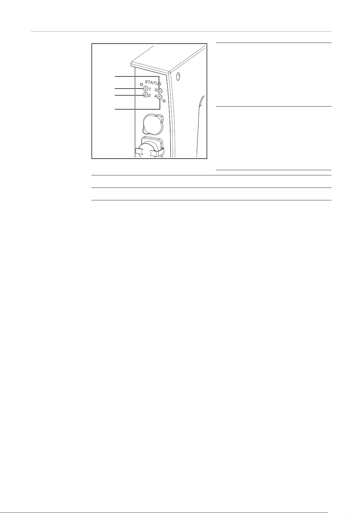
Indicators on the
(1)
(2)
(3)
(4)
Robot Interface
(1) Heartbeat LED
Off:
Offline; no supply voltage
Flashes green:
The PC board operating system
is working properly
(2) Synchronisation LED
Lights up green:
Power sources are synchronized
Lights up red:
Power sources are not synchronized
(3) see description of the respective bus module
(4) see description of the respective bus module
8
Page 9

System Overview
(1)
(2)
(3)
(4)
(1)
(2)
(3)
(4)
System Overview
EN-US
(1) Power source 1 connection / socket
(2) Wirefeeder 1 connection / socket
(3) Power source 2 connection / socket
(4) Wirefeeder 2 connection / socket
9
Page 10
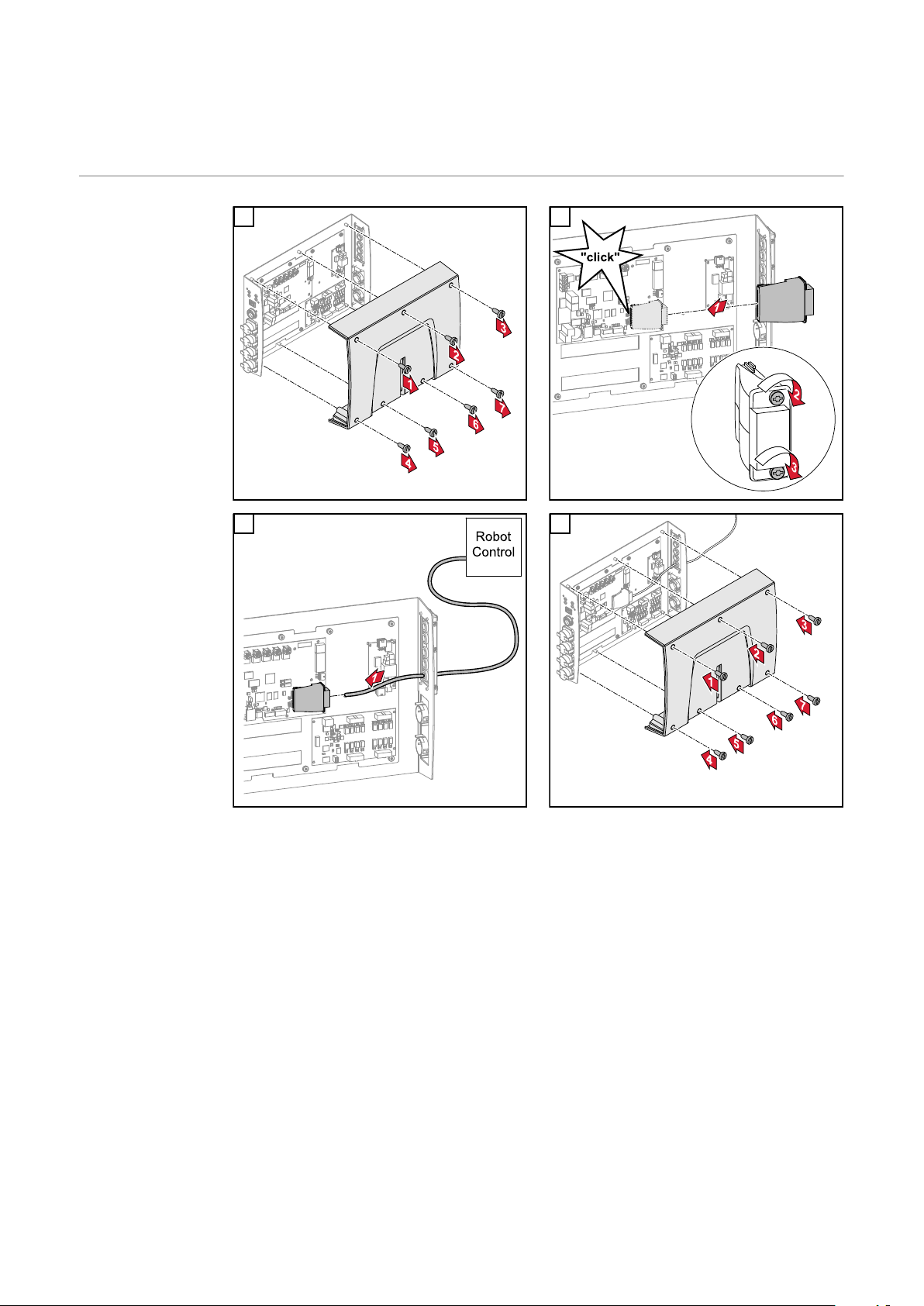
Inserting the Bus Module in the Interface and
Connecting it to the Robot Control
Inserting the
Bus Module into
the Robot Interface and Connecting it to the
Robot Control
1 2
3 4
10
Page 11
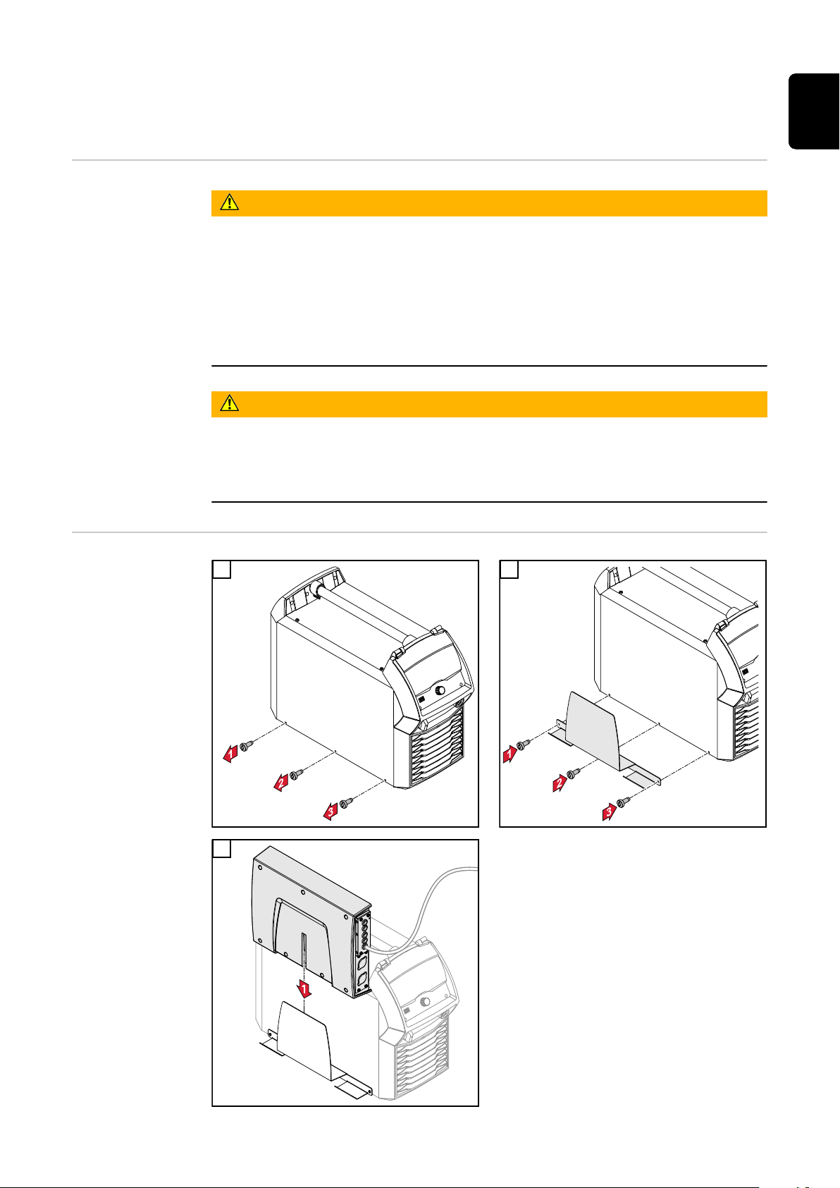
Fitting the Robot Interface and Connecting it to
the System Components
Safety
Electrical current hazard.
This can result in serious injuries or death.
▶
▶
▶
Electrical current hazard caused by an inadequate ground conductor connection.
This can result in severe personal injury and damage to property.
▶
WARNING!
Before starting work, switch off all the devices and components involved and
disconnect them from the grid.
Secure all the devices and components involved to prevent unintentional restarting.
After opening the device, use a suitable measuring instrument to check that
electrically charged components (such as capacitors) have been discharged.
WARNING!
Always use the original housing screws in the original quantity.
EN-US
Fitting the Robot
Interface
1 2
3
11
Page 12

Connecting Process Line 1 to the
Interface
1 2
3
Connecting Process Line 2 to the
Interface
Mark the process line 1 system components with the stickers supplied
4
1 2
12
Page 13

3
Mark the process line 2 system components with the stickers supplied
4
EN-US
13
Page 14

Dip Switch
General Depending on the bus module being
used, the DIP switch inside the robot
interface can be used to set the node
address/IP address.
Example: Setting
the node address/IP address
Dip switch
8 7 6 5 4 3 2 1 Node address
- - OFF OFF OFF OFF OFF ON 1
- - OFF OFF OFF OFF ON OFF 2
- - OFF OFF OFF OFF ON ON 3
- - ON ON ON ON ON OFF 62
- - ON ON ON ON ON ON 63
The node address/IP address is set using dip switch positions 1 to 6.
The setting is in binary format. This results in a configuration range of 1 to 63 in
decimal format.
14
Page 15

Notes on the Robot Interface Power Supply
(1)
(2)
(3)
Notes on the Interface Power
Supply
By default the interface is supplied with +24 V DC via connector X19 (1)
-
If the interface has connection sockets for an external power supply, these
-
sockets must be connected to connector X20 (2) or X27 (3), through which
the interface is supplied with +24 V DC
The interface can be supplied with power though connectors X19, X20, and
-
X27 in parallel. If this is the case, the interface will continue to function even
if one of the power supply lines is disconnected
If the interface is to be switched on and off via an external power supply, the
-
connection between the interface and connector X19 must be broken
EN-US
15
Page 16

Troubleshooting
(1)
(2) (3)
(4)
(5)
(6)
(7)
(10)
(8)
(9)
X3 X5X6 X7 X8
(16)
(15)
(14)
(13)
(12)
(11)
Safety
LEDs on the Robot Interface PC
board
WARNING!
Electrical current hazard.
This can result in serious injuries or death.
Before starting work, switch off all the devices and components involved and
▶
disconnect them from the grid.
Secure all the devices and components involved to prevent unintentional re-
▶
starting.
After opening the device, use a suitable measuring instrument to check that
▶
electrically charged components (such as capacitors) have been discharged.
WARNING!
Electrical current hazard caused by an inadequate ground conductor connection.
This can result in severe personal injury and damage to property.
Always use the original housing screws in the original quantity.
▶
16
Page 17

LEDs for network connection diagnosis:
(1) LED LINK
Lights up orange:
Transmission speed 100 Mbps
Off:
Transmission speed 10 Mbps
(2) LED LINK
Lights up orange:
Transmission speed 100 Mbps
Off:
Transmission speed 10 Mbps
(3) LED LINK
Lights up orange:
Transmission speed 100 Mbps
Off:
Transmission speed 10 Mbps
EN-US
(4) LED LINK
Lights up orange:
Transmission speed 100 Mbps
Off:
Transmission speed 10 Mbps
(5) LED ACTIVITY
Lights up orange:
A cable is connected to the X7 connector
Lights up/flashes green:
Data transfer active
(6) LED ACTIVITY
Lights up orange:
A cable is connected to the X8 connector
Lights up/flashes green:
Data transfer active
(7) LED ACTIVITY
Lights up orange:
A cable is connected to the X3 connector
Lights up/flashes green:
Data transfer active
(8) LED ACTIVITY
Lights up orange:
A cable is connected to the X5 connector
17
Page 18

Lights up/flashes green:
Data transfer active
(9) LED ACTIVITY
Lights up/flashes green:
Data transfer active
(10) LED SPEED
Lights up green:
A cable is connected to the X6 connector
(11) LED LINK
Not assigned
(12) LED LINK
Not assigned
(13) LED LINK
Not assigned
(14) LED USER3
Lights up/flashes green:
For fault analysis
(15) LED USER4
Flashes green:
The PC board operating system is working properly
LEDs for power supply diagnosis:
(16) LED +5V
Lights up green:
5 V operating voltage present
Off:
No operating voltage present
18
Page 19

EN-US
19
Page 20

 Loading...