


Fronius prints on elemental chlorine free paper (ECF) sourced from certified sustainable forests (FSC).
/ Perfect Charging / Perfect Welding / Solar Energy
RI FB/i Yaskawa WeldCom 2.0
RI MOD/i CC Modbus TCP-2P
Operating instructions
EN-US
42,0426,0218,EA 029-11012022


Table of contents
General 5
Safety 5
Device Concept 5
Block Diagram 6
Scope of Supply 6
Required Tools and Materials 6
Installation Requirements 6
Connections and Indicators 7
Connections on the Robot Interface 7
Pin Assignment of M12 Connection 7
LEDs on Robot Interface PCB 8
LEDs for Power Supply Diagnosis 9
LEDs for Network Connection Diagnosis 9
Connections and indicators on RJ 45 module 10
Examples of How the M12 Connection Is Used 12
Examples of How the M12 Connection Is Used 12
Technical data 13
Environmental Conditions 13
Robot Interface Technical Data 13
Data Transfer Properties 13
Configuration Parameters 14
Configuration of robot interface 15
General 15
Configuring the Process Image 15
Setting the IP Address 15
Configuring the Robot Interface 16
Installing the Robot Interface 17
Safety 17
Preparation 17
Fitting the M12 Connection 18
Routing the Data Cable 19
Installing the Robot Interface 20
Final Tasks 20
Installing the Bus Module 21
Safety 21
Installing the Bus Module 21
Input and output signals 22
Data types 22
Input Signals 22
Value range Process line selection 25
Value Range for TWIN Mode 25
Value Range for Documentation mode 26
Value range Working mode 26
Value Range for Command value selection 26
Output signals 27
Value Range for Welding Process and Process Image 30
Assignment of Sensor Statuses 1–3 30
Value range Safety status 30
TAG Table 31
Retrofit Image Input and Output Signals 34
Input signals 34
Value Range for Operating Mode 35
Output Signals 37
TAG Table 38
Modbus – General Information 40
Protocol Description 40
Data Coding 40
Application Data Unit (ADU) 41
Modbus Functions 42
03 (03) Read Holding Register 42
EN-US
3

06 (06) Write Single Register 43
16 (10) Write Multiple Register 44
23 (17) Read/Write Multiple Register 46
103 (67) Read Holding Register Float 47
104 (68) Write Single Register Float 48
4
General
(3)(1) (2) (5)(4)
Robot
Control
(6) (7) (8)
EN-US
Safety
WARNING!
Danger from incorrect operation and work that is not carried out properly.
This can result in serious personal injury and damage to property.
All the work and functions described in this document must only be carried out by
▶
technically trained and qualified personnel.
Read and understand this document in full.
▶
Read and understand all safety rules and user documentation for this equipment
▶
and all system components.
WARNING!
Danger from electrical current.
This can result in serious personal injury and damage to property.
Before starting work, switch off all devices and components involved, and discon-
▶
nect them from the grid.
Secure all devices and components involved so they cannot be switched back on.
▶
WARNING!
Danger from unplanned signal transmission.
This can result in serious personal injury and damage to property.
Do not transfer safety signals via the interface.
▶
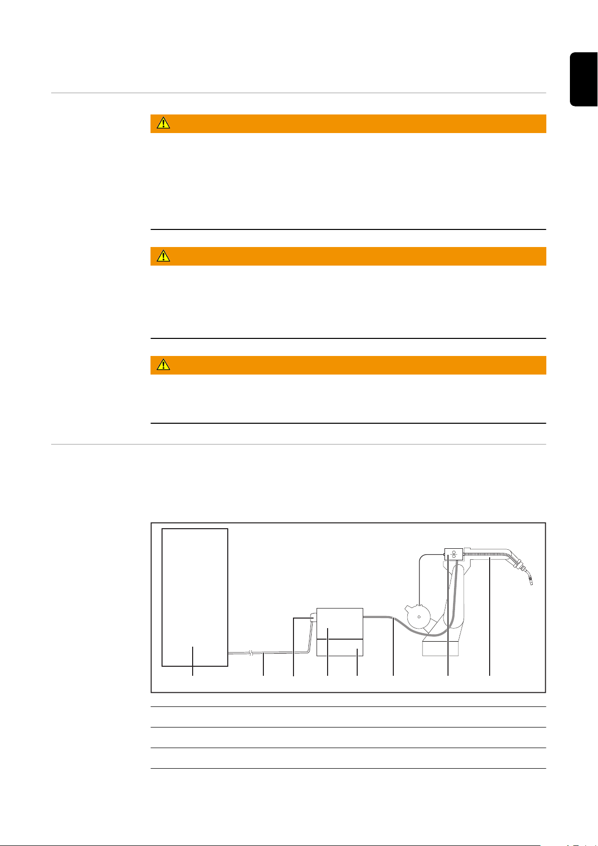
Device Concept The robot interface serves as an interface between the power source and standardized
bus modules supporting a wide range of communication protocols.
Fronius may factory-fit the robot interface in the power source but it can also be retrofitted by appropriately trained and qualified personnel.
(1) Robot control system
(2) SpeedNet data cable
(3) Robot interface
(4) Power source
5

Block Diagram
Spider NT241
RI FB/i Yaskawa
WeldCom 2.0
Data
24 V
Module
(1)
(2)
(4)
(5)
(3)
(5) Cooling unit
(6) Interconnecting hosepack
(7) Wirefeeder
(8) Robot
Scope of Supply
Required Tools
and Materials
(1) RI FB/i Yaskawa WeldCom 2.0
(2) Data cable
4-pin
(3) M12 connection (5-pin)
with connection cable
(4) Cable ties
(5) 2 screws for M12 connection
(6) These Operating Instructions
(not pictured)
- Screwdriver TX8
- Screwdriver TX20
- Screwdriver TX25
- Diagonal cutting pliers
Installation Requirements
The robot interface may only be installed in the designated opening on the rear of the
power source.
6
Connections and Indicators
(2) (3)
(1)
(1) (2)
(3)(4)
(5)
EN-US
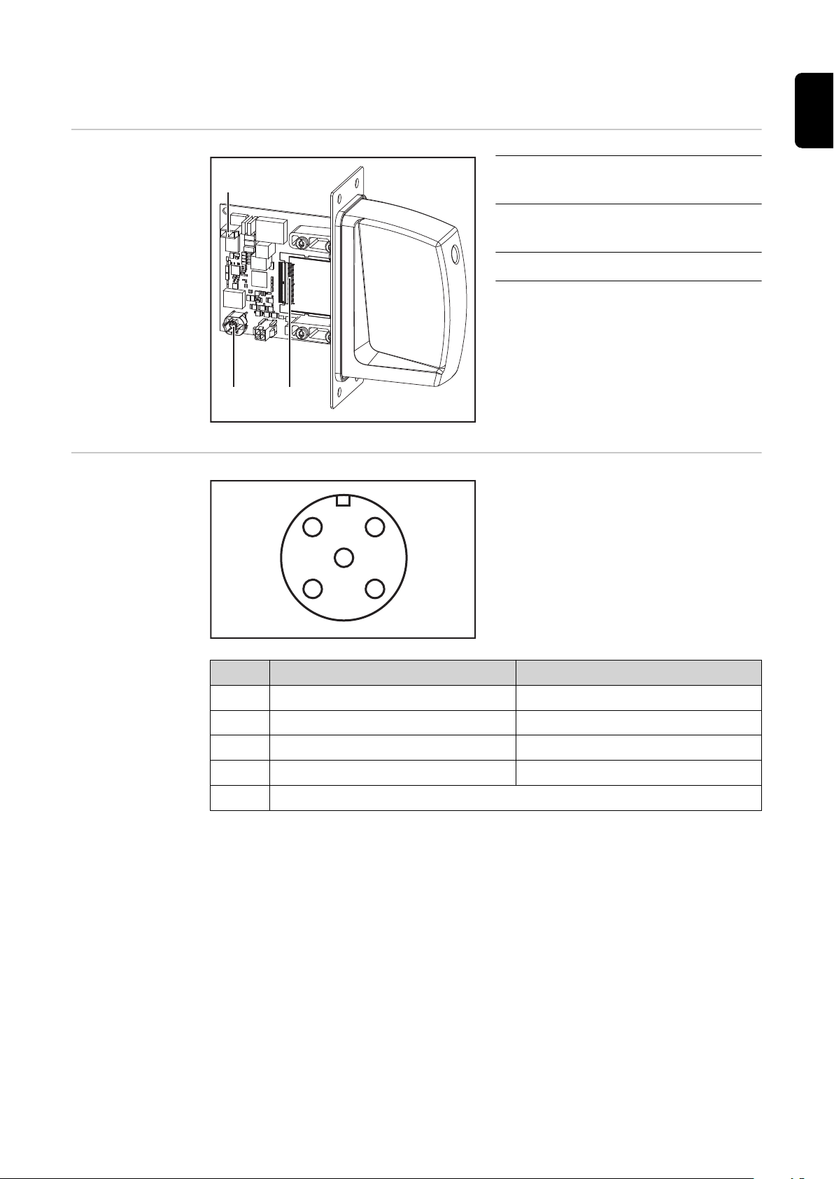
Connections on
the Robot Interface
Pin Assignment
of M12 Connection
(1) Power supply connection
2-pin
(2) SpeedNet data cableconnection
4-pin
(3) Bus module connection
WeldCom 2.0 Retrofit
(1) CAT signal CAT signal
(2) Touched Arc stable
(3) CAT signal GND CAT signal GND
(4) Touched GND Arc stable GND
(5) n.c (not connected)
7

LEDs on Robot
(14)
(13)
(12)
(11)
(2)
(1)
(9)
(10)
(8)
(7)
(3) (4)
(5) (6)
Interface PCB
(1) ETH1 LED Green For diagnosing the network connection.
For details, see section below titled "LEDs
(2) ETH2 LED Orange
for Network Connection Diagnosis"
(3) LED 3 Green
No function
(4) LED 4 Green
- Flashes at 4 Hz = No SpeedNet connection
(5) LED 5 Green
- Flashes at 20 Hz = Establishing
SpeedNet connection
- Flashes at 1 Hz = SpeedNet connection established
Lights up when an internal error occurs.
(6) LED 6 Red
Remedy: Restart the robot interface. If this
does not resolve the issue, inform the service team.
(7) +3V3 LED Green For diagnosing the power supply.
For details, see section below titled "LEDs
(8) +24V LED Green
for Power Supply Diagnosis"
(9) DIG OUT 2 LED Green Digital output 2. LED lights up when active
(10) DIG OUT 1 LED Green Digital output 1. LED lights up when active
8

(11) LED 11 Green
LEDs for Power
Supply Diagnosis
(12) LED 12 Green
(13) LED 13 Green
(14) LED 14 Green
LED Indicator Meaning Cause
Off
+24V
Lights up
Off
+3V3
Lights up
No supply voltage available for
interface
24 VDC supply voltage
present on robot interface
No operating voltage present
on robot interface
3 VDC operating voltage
present on robot interface
No function
- Robot interface power
supply not established
- Power supply cable faulty
- 24 VDC supply voltage
not present
- Robot interface power
supply unit is faulty
EN-US
LEDs for Network
Connection Diagnosis
LED Indicator Meaning Cause
- No network connection
ETH1
ETH2
Off No network connection
Lights up
Flashes Data transfer in progress
Off Transmission speed 10 Mbit/s
Lights up
Network connection established
Transmission speed
100 Mbit/s
established for interface
- Network cable faulty
9

Connections and
(12)(11)(10)
(14)(13)
(9)
(1)
(2)
(3)
(4)
(5)
(6)
(7)
(8)
indicators on RJ
45 module
(11) RJ-45 Ethernet connection 2
(12) RJ-45 Ethernet connection 1
(13) Link/Activity LED 1
(14) Network status LED
(1) TX+
(2) TX-
(3) RX+
(6) RX-
(4) Not normally used; to ensure
(5)
(7)
(8)
signal completeness, these pins
must be interconnected and,
after passing through a filter circuit, must terminate at the
ground conductor (PE).
(9) Link/Activity LED 2
(10) Module status LED
Network Status LED:
Status Meaning
Off No IP address or exception state
Lights up green At least one Modbus message received
Flashes green Waiting for first Modbus message
Lights up red IP address conflict, serious error
Flashes red Connection timeout. No Modbus message was received
within the period defined for the "Process active timeout"
Module Status LED:
Status Meaning
Off No supply voltage
Lights up green Normal operation
Lights up red Major error (exception state, serious fault, etc.)
Flashes red Minor error
Alternates between red
Firmware update in progress
and green
10
Link/Activity LED:
Status Meaning
Off No connection, no activity
Lights up green Connection established (100 Mbit/s)
Flickers green Activity (100 Mbit/s)
Lights up yellow Connection established (10 Mbit/s)

Link/Activity LED:
Status Meaning
Flickers yellow Activity (10 Mbit/s)
EN-US
11

Examples of How the M12 Connection Is Used
1 2
34
5
Pin 1 / M12
Pin 3 / M12
Pin 3 / M12
Pin 1 / M12
High-active =
Low-active =
+ 24 V from
+ 24 V from
+ 24 V
DC
/ 20 mA
+ 24 V
DC
/ 20 mA
uP
uP
max. 100 V
LED (10)
V
CC
V
CC
LED (10)
max. 100 V
Pin 2 / M12
Pin 4 / M12
Pin 4 / M12
Pin 2 / M12
High-active =
Low-active =
+ 24 V from
+ 24 V from
+ 24 V
DC
/ 20 mA
+ 24 V
DC
/ 20 mA
uP
uP
max. 100 V
max. 100 V
LED (9)
LED (9)
V
CC
V
CC
Examples of How
the M12 Connection Is Used
M12 Connection on Power Source
12
CAT signal (DIG OUT 1)
WeldCom 2.0 = Touched, Retrofit = Arc Stable (DIG OUT 2)

Technical data
EN-US
Environmental
Conditions
Robot Interface
Technical Data
CAUTION!
A risk is posed by prohibited environmental conditions.
This can result in severe damage to equipment.
Only store and operate the device under the following environmental conditions.
▶
Temperature range of ambient air:
- During operation: -10 °C to +40 °C (14 °F to 104 °F)
- During transport and storage: -20 °C to +55 °C (-4 °F to 131 °F)
Relative humidity:
- Up to 50% at 40 °C (104 °F)
- Up to 90% at 20 °C (68 °F)
Ambient air: free of dust, acids, corrosive gases or substances, etc.
Altitude above sea level: up to 2000 m (6500 ft).
Power supply Internal (24 V)
Degree of protection IP 23
Data Transfer
Properties
RJ-45 Connection
Transmission technology:
Ethernet
Medium (4 x 2 twisted-pair copper cable):
Category 5 (100 Mbit/s) or higher
Transmission speed:
10 Mbit/s or 100 Mbit/s
Bus connection:
Ethernet RJ-45
M12 Connection
Voltage:
24 V
Current load per output:
Max. 20 mA
13

Configuration
Parameters
In some robot control systems, it may be necessary to state the configuration
parameters described here so that the bus module can communicate with the
robot.
Parameter Value
Vendor Name Fronius International GmbH
Product Code 0340
hex
(832
dec
)
Major / Minor Revision V1.00
Vendor URL www.fronius.com
Product Name yaskawa-weldcom2-0-modbus-tcp
Model Name yaskawa-weldcom2-0
User Application Name Fronius welding controller for the series TPS/i WeldCom2.0
(ModbusTCP)
14
Configuration of robot interface
(1)
(2)
EN-US
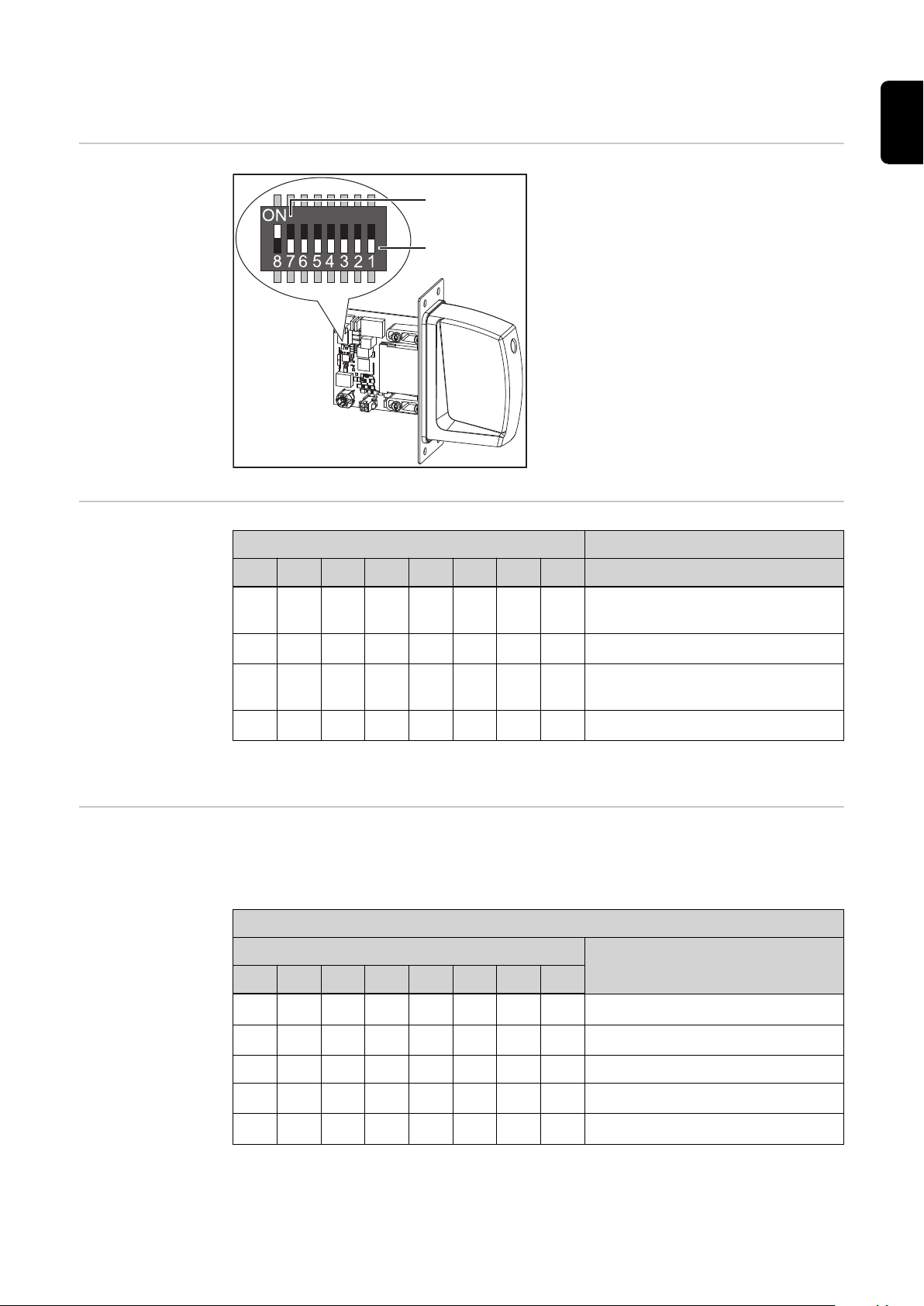
General
Configuring the
Process Image
The DIP switch on the robot interface is
used to configure:
- The process image (standard image,
retrofit image)
- The IP address
Default setting for process image:
Positions 7 and 8 of DIP switch set to OFF
(1) = standard image = Weldcom V2.0
Default setting for IP address =
192.168.255.210:
- Positions 6, 5, 3, and 1 of DIP switch
set to OFF (1)
- Positions 2 and 4 of DIP switch set to
ON (2)
DIP Switch
8 7 6 5 4 3 2 1 Configuration
OFF OFF
OFF ON
- - - - - -
- - - - - -
Standard image
(Weldcom V2.0)
Not used
Setting the IP Address
ON OFF
ON ON
- - - - - -
- - - - - -
Retrofit image
(Weldcom TPS series)
Not used
The process image defines the volume of data transferred and the system compatibility.
You can set the IP address as follows:
- Via the DIP switch within the range defined by 192.168.255.2xx
(xx = DIP switch setting = 01 to 55)
Setting the Address via the DIP Switch:
DIP Switch
IP Address
8 7 6 5 4 3 2 1
- -
- -
OFF OFF OFF OFF OFF ON
OFF OFF OFF OFF ON OFF
192.168.255.201
192.168.255.202
:
- -
- -
ON ON OFF ON ON OFF
ON ON OFF ON ON ON
192.168.255.254
192.168.255.255
The IP address can be set via positions 1 to 6 of the DIP switch.
The configuration is carried out in binary format. In decimal format, the setting range is
01 through 55.
15

The following IP address is set via the DIP switch on delivery:
- IP address: 192.168.255.210
- Subnet mask: 255.255.255.0
- Default gateway: 0.0.0.0
Configuring the
Robot Interface
Set the DIP switch in accordance with the desired configuration
1
NOTE!
Risk due to invalid DIP switch settings.
This may result in malfunctions.
Whenever changes are made to the DIP switch settings, the interface must be re-
▶
started. This is the only way for the changes to take effect.
Restart the interface = interrupting and restoring the power supply or executing the
▶
relevant function on the website of the power source (SmartManager).
16

Installing the Robot Interface
EN-US
Safety
Preparation
WARNING!
Electrical current hazard.
This can result in serious injuries or death.
Before starting work, switch off all the devices and components involved and discon-
▶
nect them from the grid.
Secure all the devices and components involved to prevent unintentional restarting.
▶
After opening the device, use a suitable measuring instrument to check that electric-
▶
ally charged components (such as capacitors) have been discharged.
WARNING!
Electrical current hazard caused by an inadequate ground conductor connection.
This can result in severe personal injury and damage to property.
Always use the original housing screws in the original quantity.
▶
1 2
3 4
17

5
Fitting the M12
Connection
1 2
3 4
18

5 6
EN-US
Routing the Data
Cable
1 2
3
19

Installing the Robot Interface
1 2
Final Tasks
1 2
20

Installing the Bus Module
EN-US
Safety
Installing the Bus
Module
WARNING!
Danger from electrical current.
Serious injuries or death may result.
Before starting work, switch off all devices and components involved, and discon-
▶
nect them from the grid.
Secure all devices and components involved so that they cannot be switched back
▶
on.
WARNING!
Danger from electrical current due to inadequate ground conductor connection.
Serious personal injury and property damage may result.
Always use the original housing screws in the quantity initially supplied.
▶
1 2
3
21

Input and output signals
Data types The following data types are used:
- UINT16 (Unsigned Integer)
Whole number in the range from 0 to 65535
- SINT16 (Signed Integer)
Whole number in the range from -32768 to 32767
Conversion examples:
- for a positive value (SINT16)
e.g. desired wire speed x factor
12.3 m/min x 100 = 1230
- for a negative value (SINT16)
e.g. arc correction x factor
-6.4 x 10 = -64
Input Signals From robot to power source
Applicable to firmware V2.3.0 and higher
= FFC0
dec
= 04CE
dec
hex
hex
HEX
Ad-
ress Signal Type
F000 Control Flag Group 1
Bits 0 to 7 Process active timeout Byte ms 10
F001
Bits 8 to
15
Control Flag Group 2
Bit 0 Welding start Boolean
Bit 1 Robot ready Boolean
Bit 2 Source error reset Boolean
Bit 3 Gas on Boolean
Bit 4 Wire inching Boolean
Bit 5 Wire retract Boolean
Bit 6 Torch blow out Boolean
Bit 7 Welding simulation Boolean
Bit 8 Touch sensing Boolean
Bit 9 Reserved
Bit 10 SFI ON Boolean
Reserved
Range /
Unit
Factor
22
Bit 11 Synchro pulse on Boolean
Bit 12 WireBrake Boolean
Bit 13 Torch XChange Boolean
Bit 14 TeachMode Boolean
Bit 15 Reserved

HEX
Ad-
ress Signal Type
F002 Control Flag Group 3
Range /
Unit
Factor
EN-US
Bit 0 Process line selection Bit
0
Bit 1 Process line selection Bit
1
Bit 2 TWIN mode Bit 0 Boolean
Bit 3 TWIN mode Bit 1
Bits 4 to 9 Reserved
Bit 10 Active heat control Boolean
Bit 11 Wire sense start Boolean
Bit 12 Wire sense break Boolean
Bits 13 to15Reserved Boolean
Boolean
See section
Value
range Pro-
Boolean
Boolean
cess line
selection on
page 25
See section
Value
Range for
TWIN Mode
on page 25
F003 Control Flag Group 4
Bit 0 Documentation mode Boolean See section
Value
Range for
Documenta-
tion mode
on page 26
Bits 1 to
15
F004 Control Flag Group 5
Bits 0 to
15
F005 Control Flag Group 6
Bits 0 to
15
F006 Control Flag Group 7
Bits 0 to
15
Reserved
Reserved
Reserved
Reserved
23

HEX
Ad-
ress Signal Type
F007 Control Flag Group 8
Range /
Unit
Factor
F008
Bit 0 ExtInput1 => OPT_Out-
put 1
Bit 1 ExtInput2 => OPT_Out-
put 2
Bit 2 ExtInput3 => OPT_Out-
put 3
Bit 3 ExtInput4 => OPT_Out-
put 4
Bit 4 ExtInput5 => OPT_Out-
put 5
Bit 5 ExtInput6 => OPT_Out-
put 6
Bit 6 ExtInput7 => OPT_Out-
put 7
Bit 7 ExtInput8 => OPT_Out-
put 8
Bits 8 to
15
Working mode
Bit 0 Working Mode Bit 0
Bit 1 Working Mode Bit 1
Bit 2 Working Mode Bit 2
Bit 3 Working Mode Bit 3
Bit 4 Working Mode Bit 4
Bits 5 to
13
Reserved
Reserved
Boolean
Boolean
Boolean
Boolean
Boolean
Boolean
Boolean
Boolean
See section
Value
range
Working
mode on
page 26
Bit 14 Command value selec-
tion
Bit 15 Reserved
F009 Job number UINT16 0 to 1000
F00A Program number (xml-file) UINT16 0 to 65,535
F00B Feeder command Value SINT16 -327.68 to
F00C Arc length correction SINT16 -10 to +10 10
F00D Puls/Dynamik correction SINT16 -10 to +10 10
F00E Wire retract SINT16 0 to +10 10
Boolean See section
Value
Range for
Command
value selection on page
26
100
327.67
[m/min]
24

HEX
Ad-
ress Signal Type
Range /
Unit
F00F Welding speed UINT16 0 to 65,535
(0 to 6553.5
10
m/min)
F010 Penetration stabilizer SINT16 0 to +10 10
F011 Arc length stabilizer UINT16 0 to +10 10
F012 Reserved
F013 Reserved
F014 Reserved
F015 Reserved
F016 Reserved
F017 Reserved
F018 Reserved
F019 Reserved
Factor
EN-US
Value range Process line selection
F01A Wire forward / backward length UINT16 OFF / 1 to
65,535 mm
F01B Wire sense edge detection UINT16 OFF / 0.5 to
20.0 mm
F01C Reserved
F01D Seam number UINT16 0 to 65,535 1
Bit 1 Bit 0 Description
0 0 Process line 1 (default)
0 1 Process line 2
1 0 Process line 3
1 1 Reserved
Value range for process line selection
1
10
Value Range for
TWIN Mode
Bit 1 Bit 0 Description
0 0 TWIN Single mode
0 1 TWIN Lead mode
1 0 TWIN Trail mode
1 1 Reserved
Value range for TWIN mode
25

Value Range for
Documentation
mode
Bit 0 Description
0 Seam number of power source (internal)
1 Seam number of robot
Value range for documentation mode
Value range
Working mode
Value Range for
Command value
selection
Bit 4 Bit 3 Bit 2 Bit 1 Bit 0 Description
0 0 0 0 0 Internal parameter selection
0 0 0 0 1 Special 2-step mode characteristics
0 0 0 1 0 Job mode
0 1 0 0 0 2-step mode characteristics
Value range for operating mode
Bit 14 Description
0 Wirefeeder set value
1 Welding current set value
Value range for set value
26

Output signals From Power Source to Robot
Applicable to firmware V2.3.0 and higher
HEX
Ad-
ress Signal Type
F100 Status Flag Group 1
Bit 0 = 15 Reserved
Range /
Unit
EN-US
Factor
F101
Status Flag Group 2
Bit 0 Heartbeat Powersource Boolean 1
Hz
Bit 1 Power source ready Boolean
Bit 2 Arc stable Boolean
Bit 3 Current flow Boolean
Bit 4 Main current signal Boolean
Bit 5 Torch collision protection Boolean
Bit 6 Reserved
Bit 7 Reserved
Bit 8 Touched Boolean
Bit 9 Torchbody connected Boolean
Bit 10 Command value out of
range
Bit 11 Correction out of range Boolean
Bit 12 Process active Boolean
Bit 13 RobotMotionRelease Boolean
Boolean
F102
Bit 14 Wire stick workpiece Boolean
Bit 15 Reserved
Status Flag Group 3
Bit 0 Welding Mode Bit 0 Boolean See section
Bit 1 Welding Mode Bit 1 Boolean
Bit 2 Welding Mode Bit 2 Boolean
Bit 3 Welding Mode Bit 3 Boolean
Bit 4 Welding Mode Bit 4 Boolean
Bit 5 = 7 Reserved
Bit 8 Parameter selection in-
ternally
Bit 9 Characteristic number
valid
Bit 10 =
13
Bit 14 Process image Bit 0 Boolean
Bit 15 Process image Bit 1 Boolean
Reserved
Boolean
Boolean
Value
Range for
Welding
Process
and Pro-
cess Image
on page 30
27

HEX
Ad-
ress Signal Type
F103 Status Flag Group 4
Bit 0 Penetration stabilizier Boolean
Bit 1 Arclength stabilizier Boolean
Bit 2 = 15 Reserved
F104 Status Flag Group 5
Range /
Unit
Factor
Bit 0 Sensor status 1 High Boolean See section
Bit 1 Sensor status 2 High Boolean
Bit 2 Sensor status 3 High Boolean
Bit 3 = 10 Reserved
Bit 11 Safety status Bit 0 Boolean See section
Bit 12 Safety status Bit 1 Boolean
Bit 13 Reserved
Bit 14 Notification Boolean
Bit 15 System not ready Boolean
F105 Status Flag Group 6
Bit 0 Limit Signal Boolean
Bit 1 = 7 Reserved
Assign-
ment of
Sensor
Statuses 1–
3 on page
30
Value
range
Safety
status on
page 30
Bit 8 Reserved
Bit 9 TWIN synchronization
active
Bit 10 Line supply status Boolean
Bit 11 =
13
Bit 14 Warning Boolean
Bit 15 Reserved
F106 Status Flag Group 7
Bit 0 = 15 Reserved Boolean
Reserved
Boolean
28

HEX
Ad-
ress Signal Type
F107 Status Flag Group 8
Range /
Unit
Factor
EN-US
Bit 0 ExtOutput1 <= OPT_In-
put1
Bit 1 ExtOutput2 <= OPT_In-
put2
Bit 2 ExtOutput3 <= OPT_In-
put3
Bit 3 ExtOutput4 <= OPT_In-
put4
Bit 4 ExtOutput5 <= OPT_In-
put5
Bit 5 ExtOutput6 <= OPT_In-
put6
Bit 6 ExtOutput7 <= OPT_In-
put7
Bit 7 ExtOutput8 <= OPT_In-
put8
Bit 8 = 15 Reserved Boolean
F108 Main error number UINT16 0 to 65,535
F109 Warning number UINT16 0 to 65,535 1
Boolean
Boolean
Boolean
Boolean
Boolean
Boolean
Boolean
Boolean
F10A Welding voltage actual value UINT16 0.0 to
327.67 volts
F10B Welding current actual value UINT16 0.0 to
3276.7
amperes
F10C Motor current actual value M1 SINT16 -327.68 to
327.67
amperes
F10D Motor current actual value M2 SINT16 -327.68 to
327.67
amperes
F10E Motor current actual value M3 SINT16 -327.68 to
327.67
amperes
F10F Reserved
F110 Wire speed actual value SINT16 -327.68 to
327.67
m/min
F111 Seam tracking actual value UINT16 0 to 6.5535 10000
F112 Real energy actual value UINT16 0 to 6553.5
kilojoules
100
10
100
100
100
100
10
F113 Wire position SINT16 -327.68 to
327.67 mm
F114 Reserved
F115 Reserved
100
29

HEX
Ad-
ress Signal Type
Range /
Unit
F116 Reserved
F117 Reserved
F118 Reserved
F119 Reserved
F11A Reserved
F11B Reserved
F11C Reserved
F11D Reserved
Factor
Value Range for
Welding Process
and Process Image
Bit 4 Bit 3 Bit 2 Bit 1 Bit 0 Description
0 0 0 0 0 Internal mode selection
0 0 0 0 1 MIG/MAG pulsed synergic
0 0 0 1 0 MIG/MAG standard synergic
0 0 0 1 1 MIG/MAG PMC
0 0 1 0 0 MIG/MAG LSC
0 0 1 0 1 MIG/MAG standard manual
0 0 1 1 0 Electrode
0 0 1 1 1 TIG
0 1 0 0 0 CMT
Value range for welding process
Bit 15 Bit 14 Bit 0-13 Description
0 0 - Standard image (Weldcom V2.0)
1 0 - Retrofit image (Weldcom TPS series)
Value range for process image
Assignment of
Sensor Statuses
1–3
Value range
Safety status
30
Bit 2 Bit 1 Bit 0 Description
0 0 1 OPT/i WF R wire end
0 1 0 OPT/i WF R DE wire drum
1 0 0 OPT/i WF R DE ring sensor
Bit 1 Bit 0 Description
0 0 Reserve
0 1 Hold

TAG Table
Bit 1 Bit 0 Description
1 0 Stop
1 1 Not installed / active
EN-US
- To read the following TAGs, use the mode function 03dec (03hex) - see section 03
dec
(03
hex
) Read
Holding Register from page 42
- To edit the following TAGs, use the mode function 06dec (06hex) - see section 06
dec
(06
hex
) Write
Single Register from page 43
HEX
address Description Reading / writing Unit Type Step size
E064 Gas preflow [Gpr] Reading & writing s Word 0.1
E065 Gas postflow [Gpo] Reading & writing s Word 0.1
E098 Error number Read only 1
E062 Min. feeder value Read only m/min Word 0.1
E063 Max. feeder value Read only m/min Word 0.1
E0A3 Inching speed [Fdi] Reading & writing m/min Word 0.1
E032 SynchroPulse DeltaWireFeed Reading & writing m/min Word
E031 SynchroPulse Frequency Reading & writing Hz Word 0.1
E033 SynchroPulse DutyCycle Reading & writing % Word 1
E034 SynchroPulse
Reading & writing 0.1
ArcLength Correction High
E035 SynchroPulse
Reading & writing 0.1
ArcLength Correction Low
E06A Starting current [I-S] Reading & writing % Word 1
E06B Slope 1 Reading & writing s Word 0.1
E06C Slope 2 Reading & writing s Word 0.1
E06D End current [I-E] Reading & writing % Word 1
E056 Starting Current Time [t-S] Reading & writing s Word 0.1
OFF=12e34
E057 End Current Time [t-e] Reading & writing s Word 0.1
OFF=12e34
E02E SFI HotStart Reading & writing s Word 0.01
31

HEX
address Description Reading / writing Unit Type Step size
E06F Language Reading & writing Con-
Name: Language
Constant: English (8e34)
Constant: German (9e34)
Constant: Chinese (10e34)
Constant: Spanish (23e34)
Constant: French (24e34)
Constant: Czech (25e34)
Constant: Hungarian (26e34)
Constant: Italian (27e34)
Constant: Norwegian (28e34)
Constant: Polish (29e34)
Constant: Portuguese (30e34)
Constant: Slovak (31e34)
Constant: Turkish (32e34)
Constant: Russian (33e34)
Constant: Swedish (34e34)
stant
Float
Constant: Estonian (35e34)
Constant: Finnish (36e34)
Constant: Lithuanian (39e34)
Constant: Latvian (40e34)
Constant: Dutch (41e34)
Constant: Slovenian (42e34)
Constant: Romanian (43e34)
Constant: Croatian (44e34)
Constant: Japanese (58e34)
Constant: Ukrainian (59e34)
Constant: Korean (61e34)
Constant: Icelandic (66e34)
Constant: Vietnamese (67e34)
Constant: Thai (70e34)
Constant: Indonesian (71e34)
Constant: Serbian (75e34)
Constant: Hindi (76e34)
Constant: Tamil (130e34)
Constant: Danish (151e34)
Constant: Bulgarian (156e34)
E0A6 Hourmeter Current flow Read only h Float 0.1
E0A7 Hourmeter Power on Read only h Float 0.1
32

HEX
address Description Reading / writing Unit Type Step size
E0AA Power value Read only kW Float 0.1
E0AB Real energy value Read only kJ Float 0.1
E0BB Coolertemperature Read only C Float 0.1
E0BC Coolerflow Read only l/min Float 0.01
EN-US
33

Retrofit Image Input and Output Signals
Input signals From robot to power source
Applicable to firmware V1.9.0 and higher
HEX
address Signal Type Range / Unit
F000
F001
Control Flag Group 1
Bits 0 to 7 Process active timeout Byte [ms] 10
Bits 8 to 15 Reserved
Control Flag Group 2
Bit 0 Welding start Boolean
Bit 1 Robot ready Boolean
Bit 2 Source error reset Boolean
Bit 3 Gas test Boolean
Bit 4 Wire inching Boolean
Bit 5 Wire retract Boolean
Bit 6 Torch blow out Boolean
Bit 7 Welding simulation Boolean
Bit 8 Touch sensing Boolean
Bit 9 Reserved
Bit 10 SFI on Boolean
Factor
Bit 11 Synchro pulse on Boolean
Bits 12 to
13
Bit 14 Power full range Boolean
Bit 15 Reserved
F002 Control Flag Group 3
Bits 0 to 15 Reserved
F003 Control Flag Group 4
Bits 0 to 15 Reserved
F004 Control Flag Group 5
Bits 0 to 15 Reserved
F005 Control Flag Group 6
Bits 0 to 15 Reserved
F006 Control Flag Group 7
Bits 0 to 15 Reserved
F007 Control Flag Group 8
Bits 0 to 15 Reserved
Reserved
34

HEX
address Signal Type Range / Unit
Factor
F008
F009 Job number Byte 0 to 255
F00A Program number Byte 0 to 127
F00B Power Word 0 to 65,535
F00C Arc length correction Word 0 to 65,535
F00D Pulse-/dynamic correction Byte 0 to 255
F00E Reserved
F00F Reserved
F010 Reserved
F011 Reserved
Operating mode
Bit 0 Operating mode 0 Boolean
Bit 1 Operating mode 1 Boolean
Bit 2 Operating mode 2 Boolean
Bit 3 Operating mode 3 Boolean
Bits 4 to 15 Reserved Boolean
See table Value
Range for Oper-
ating Mode on
page 35
(0 to 100%)
(-10 to +10%)
(-5 to +5%)
EN-US
F012 Reserved
F013 Reserved
F014 Reserved
F015 Reserved
F016 Reserved
F017 Reserved
F018 Reserved
F019 Reserved
F01A Reserved
F01B Reserved
F01C Reserved
F01D Reserved
F01E Reserved
Value Range for
Operating Mode
Bit
4-15
Bit 3 Bit 2 Bit 1 Bit 0 Description
- 0 0 0 0 MIG standard
- 0 0 0 1 MIG pulse
- 0 0 1 0 Job mode
- 0 0 1 1
Internal parameter selection/special 2step mode
35

Bit
4-15
- 0 1 0 0 Synergic operation/special 2-step mode
- 0 1 0 1 Synergic operation/special 2-step mode
- 0 1 1 0 MIG standard manual
- 0 1 1 1 Synergic operation/special 2-step mode
- 1 0 0 0 MIG LSC
- 1 0 0 1 MIG PMC
Bit 3 Bit 2 Bit 1 Bit 0 Description
36

Output Signals From Power Source to Robot
Applicable to firmware V1.9.0 and higher
HEX
Ad-
ress Signal Type
F100 Status Flag Group 1
Range /
Unit
EN-US
Factor
F101
Bits 0 to
15
Status Flag Group 2
Bit 0 Communication ready Boolean
Bit 1 Power source ready Boolean
Bit 2 Arc stable Boolean
Bit 3 Process active Boolean
Bit 4 Main current signal Boolean
Bit 5 Torch collision protection Boolean
Bit 6 Wire stick control Boolean
Bit 7 Wire available Boolean
Bit 8 Short circuit timeout Boolean
Bit 9 Power out of Range Boolean
Bits 10 to11- Boolean
Bit 12 Limit signal High Boolean
Bits 13 to15- Boolean
Reserved Boolean
F102 Status Flag Group 3
Bits 0 to
13
Bit 14 Process image Bit 0 Boolean
Bit 15 Process image Bit 1 Boolean
F103 Status Flag Group 4
Bits 0 to
15
F104 Status Flag Group 5
Bits 0 to
15
F105 Status Flag Group 6
Bits 0 to
15
F106 Status Flag Group 7
Bits 0 to
15
Reserved
Reserved
Reserved
Reserved
Reserved
37

HEX
Ad-
ress Signal Type
Range /
Unit
F107 Status Flag Group 8
Factor
Bits 0 to
Reserved
15
F108 Main error number Word
F109 Reserved
F10A Welding voltage actual value Word 0 to 65535
(0 to 100 V)
F10B Welding current actual value Word 0 to 65535
(0 to
1000 A)
F10C Motor current actual value Byte 0 to 255
(0 to 5 A)
F10D Reserved
F10E Reserved
F10F Reserved
F110 Wire speed actual value Word 0 to vDmax 100
F111 Reserved
F112 Reserved
TAG Table
- To read the following TAGs, use the mode function 03dec (03hex) - see section 03
dec
(03
hex
) Read
Holding Register from page 42
- To edit the following TAGs, use the mode function 06dec (06hex) or 16
(06
) Write Single Register from page 43 / section 16
hex
dec
(10
) Write Multiple Register from page
hex
dec
(10
) - see section 06
hex
43
HEX
address Description Reading / writing Unit Type Step size
E011 Gas preflow [Gpr] Reading / writing s Word 0.001
E012 Gas postflow [Gpo] Reading / writing s Word 0.001
E000 Error number Read only 1
E072 Min. feeder value Read only m/min Word 0.01
E073 Max. feeder value Read only m/min Word 0.01
E013 Inching speed [Fdi] Reading / writing m/min Word 0.01
E015 Power offset [dFd] Reading / writing m/min Word 0.01
dec
E016 SynchroPulse Frequency Reading / writing Hz Word 0.1
E01D Starting current [I-S] Reading / writing % Word 0.1
38

HEX
address Description Reading / writing Unit Type Step size
E01F Slope 1 + Slope 2 Reading / writing s Word 0.001
E020 End current [I-E] Reading / writing % Word 0.1
E01E Starting Current Time [t-S] Reading / writing s Word OFF = 0.0 and
E021 End Current Time [t-e] Reading / writing s Word
E007 Arc length correction 2 (Al2) Reading / writing % Word 0.1
0.1
EN-US
39

Modbus – General Information
Protocol Description
The MODBUS ADU is constructed by the client that initiates the MODBUS transaction.
The function tells the server which action is to be performed. The MODBUS application
protocol defines the format of a client-initiated request.
The function code field of a MODBUS data unit is coded in one byte. Valid codes are in
the range of 1 ... 255 decimal (the range 128-255 is reserved for exception responses).
When the server receives a message from a client, the function code field tells the server
which action to perform.
If several actions are to be performed, subfunction codes are added to some function
codes. When messages are sent to servers by a client, the data field in the message
contains additional information that the server uses to perform the action defined by the
function code. This can include elements such as discrete addresses, register addresses, the quantity to be handled, or the number of actual data bytes contained within
the field.
With certain types of request, there might not be a data field (length: zero). In this case,
the server does not require any additional information because the action is specified by
the function code alone.
If a MODBUS ADU is correctly received without any errors occurring in connection with
the requested MODBUS function, the requested data will be included in the data field
when a server responds to a client. If an error does occur in connection with the requested MODBUS function, the field will contain an exception code that the server application
can use to determine what action to perform next.
For instance, a client can read the ON/OFF statuses of a group of discrete inputs or outputs, or it can read/write the data contents of a group of registers.
When sending a response to the client, the server uses the function code field either to
indicate that the response is normal (free of errors) or that an error has occurred (this
kind of response is called an "exception response"). In the case of a normal response,
the server simply echoes the original function code.
Data Coding For addresses and data elements, MODBUS uses a big-endian format. When a number
larger than a single byte is transmitted, this means that the most significant byte is sent
first.
Register Size Value
16 bits, 1234
hex
12
is sent as the first byte and then 34
hex
hex
40

Application Data
Unit (ADU)
This section describes the encapsulation method used for a MODBUS request or response when it is transmitted over a MODBUS TCP network.
MPAP header Function code Data
Description of MPAP header:
Transaction Identifier
Used to allocate the transaction. The MODBUS server copies the Transaction Identifier of the request into the response.
Transaction Identifier
This is used for transaction pairing. The MODBUS server copies the transaction identifier from the request into the response.
Length: 2 bytes
Description: For identifying a MODBUS request/response transaction
Client: Initialized by the client
Server: Copied back by the server from the request received
Protocol Identifier
This is used for multiplexing within the system. The MODBUS protocol is identified by
the value 0.
Length: 2 bytes
EN-US
Description: 0 = Modbus protocol
Client: Initialized by the client
Server: Copied back by the server from the request received
Length
This field is used to specify the number of bytes in the field to follow, including the unit
identifier, function code, and data field.
Length: 2 bytes
Description: Number of bytes to follow
Client: Initialized by the client
Server: -
Unit Identifier
This field is used for routing within the system. It is usually used for communication
with a serially connected MODBUS- or MODBUS+ slave where communication takes
place via a gateway between an Ethernet network and a serial MODBUS line. The
field value is set in the request by the MODBUS client and must be replicated exactly
in the response from the server.
Length: 1 byte
Description: For identifying a remote slave that is connected via a serial
line or other type of bus.
Client: Initialized by the client
All MODBUS/TCP ADUs are sent via TCP on registered port 502.
41

Modbus Functions
03
(03
dec
Holding Register
hex
) Read
This code is used to read the contents of a contiguous block of holding registers in a remote device. The request PDU determines the starting register address and the number
of registers.
The registers are addressed in the PDU starting at zero. This means registers numbered
1-16 will be addressed using 0-15.
The register data in the response message is packed as two bytes per register, with the
binary contents precisely aligned/justified within each byte. Within the individual registers, the first byte contains the high-order bits and the second byte the low-order bits.
Request
Function code 1 byte 03
Start address 2 bytes 0000
Number of registers 2 bytes 1 to 125 (7D
hex
to FFFF
hex
hex
hex
)
Response
Function code 1 byte 03
hex
Number of bytes 2 bytes 2 x N*
Register value N* x 2 bytes -
N* = Number of registers
Errors
Error code 1 byte 83
hex
Exception code 1 byte 01 or 02 or 03 or 04
Example
Example of a read request for register F009 (job number).
Request Response
Field name Hex Field name Hex
42
Transaction Identifier Hi 00 Transaction Identifier Hi 00
Transaction Identifier Lo 01 Transaction Identifier Lo 01
Protocol Identifier Hi 00 Protocol Identifier Hi 00
Protocol Identifier Lo 00 Protocol Identifier Lo 00
Length Hi 00 Length Hi 00
Length Lo 06 Length Lo 05
Unit Identifier 00 Unit Identifier 00
Function code 03 Function code 03
Starting Address Hi F0 Byte Count 02
Starting Address Lo F9 Register value Hi (108) 02
No. of Registers Hi 00 Register value Lo (108) 37
No. of Registers Lo 01

06
dec
(06
hex
)
Write Single Register
The contents of register F009 (job number) are displayed in the form of the two-byte values 237
hex
or 567
dec
.
This function code is used to write a single holding register in a remote device. The request PDU specifies the address of the register to be written. Registers are addressed
starting at zero. This means that the register that has been numbered as 1 will be addressed using 0.
The normal response is an echo of the request, which is returned after the register contents are written.
Request
EN-US
Function code 1 byte 06
Register address 2 bytes 0000
Register value 2 bytes 0000
hex
to FFFF
hex
or FFFF
hex
hex
hex
Response
Function code 1 byte 06
Register address 2 bytes 0000
Register value 2 bytes 0000
hex
to FFFF
hex
or FFFF
hex
hex
hex
Errors
Error code 1 byte 86
hex
Exception code 1 byte 01 or 02 or 03 or 04
Example
Example request for writing the value 237
hex
(567
) to register F009 (job num-
dec
ber).
Request Response
Field name Hex Field name Hex
Transaction Identifier Hi 00 Transaction Identifier Hi 00
Transaction Identifier Lo 01 Transaction Identifier Lo 01
Protocol Identifier Hi 00 Protocol Identifier Hi 00
Protocol Identifier Lo 00 Protocol Identifier Lo 00
Length Hi 00 Length Hi 00
Length Lo 06 Length Lo 06
Unit Identifier 00 Unit Identifier 00
Function code 06 Function code 06
Register Address Hi F0 Register Address Hi F0
Register Address Lo 09 Register Address Lo 09
Register Value Hi 02 Register Value Hi 02
Register Value Lo 37 Register Value Lo 37
43

16
dec
(10
hex
)
Write Multiple Register
This function code is used to write a block of contiguous registers in a remote device.
The requested written values are specified in the request data field. Data is packed as
two bytes per register. The normal response returns the function code, the starting address, and the number of registers written.
Request
Function code 1 byte 10
Starting address 2 bytes 0000
Number of registers 2 bytes 0001
hex
to FFFF
hex
or 0078
hex
hex
hex
Number of bytes 1 byte 2 x N*
Register values N* x 2 bytes Value
N* = number of registers to be written
Response
Function code 1 byte 10
Starting address 2 bytes 0000
Number of registers 2 bytes 1 to 123 (7B
hex
to FFFF
hex
hex
hex
)
Errors
Error code 1 byte 90
hex
Exception code 1 byte 01 or 02 or 03 or 04
Example
Example request for writing two registers (F00B
– F00C
hex
hex
).
Request Response
Field name Hex Field name Hex
Transaction Identifier Hi 00 Transaction Identifier Hi 00
Transaction Identifier Lo 01 Transaction Identifier Lo 01
Protocol Identifier Hi 00 Protocol Identifier Hi 00
Protocol Identifier Lo 00 Protocol Identifier Lo 00
Length Hi 00 Length Hi 00
Length Lo 11 Length Lo 11
Unit Identifier 00 Unit Identifier 00
Function code 10 Function code 10
Starting Address Hi F0 Starting Address Hi F0
Starting Address Lo 0B Starting Address Lo 0B
Quantity of Registers Hi 00 Quantity of Registers Hi 00
Quantity of Registers Lo 02 Quantity of Registers Lo 02
Byte Count 04
Register Value Hi 04
Register Value Lo CE
44

Example
Example request for writing two registers (F00B
– F00C
hex
hex
).
Request Response
Field name Hex Field name Hex
Register Value Hi FF
Register Value Lo C0
EN-US
45

23
dec
(17
hex
)
Read/Write Multiple Register
This function code performs a combination of one read operation and one write operation
in a single MODBUS transaction. The write operation is performed before the read operation.
Holding registers are addressed starting at zero. This means that holding registers 1-16
will be addressed in the PDU using 0-15.
The request PDU specifies:
- The starting address and number of holding registers to be read
- The starting address, number of holding registers, and data for the write operation.
The byte count field specifies the number of bytes to follow in the write data field.
The normal response contains the data from the group of registers read. The byte count
field specifies the number of bytes to follow in the read data field.
Request
Function code 1 byte 17
hex
Read starting address 2 bytes 0000
Number of registers to
2 bytes 0001
read
Write starting address 2 bytes 0000
Number of registers to
2 bytes 0001
write
Write number of bytes 1 byte 2 x N*
Write register values N* x 2 bytes
N* = number of registers to be written
Response
Function code 1 byte 17
hex
Number of bytes 1 byte 2 x N*
Write register values N* x 2 bytes
N* = number of registers to be read
Errors
to FFFF
hex
to approx. 0076
hex
to FFFF
hex
to approx. 0076
hex
hex
hex
hex
hex
46
Error code 1 byte 97
hex
Exception code 1 byte 01 or 02 or 03 or 04
Example
Example request for reading 2 registers and writing 2 registers.
Request Response
Field name Hex Field name Hex
Transaction Identifier Hi 00 Transaction Identifier Hi 00
Transaction Identifier Lo 01 Transaction Identifier Lo 01
Protocol Identifier Hi 00 Protocol Identifier Hi 00
Protocol Identifier Lo 00 Protocol Identifier Lo 00
Length Hi 00 Length Hi 00

Example
Example request for reading 2 registers and writing 2 registers.
Request Response
Field name Hex Field name Hex
Length Lo 11 Length Lo 7
Unit Identifier 00 Unit Identifier 00
Function code 17 Function code 17
Read Starting Address Hi F1 Byte Count 2
Read Starting Address Lo 0A Read Registers Value Hi 04
Quantity to Read Hi 00 Read Registers Value Lo 08
Quantity to Read Lo 2 Read Registers Value Hi 0A
Write Starting Address Hi F0 Read Registers Value Lo C8
Write Starting Address Lo 0B
Quantity to Write Hi 00
Quantity to Write Lo 04
Write Byte Count 2
Write Registers Value Hi 04
Write Registers Value Lo CE
Write Registers Value Hi FF
EN-US
103
dec
(67
hex
)
Read Holding Register Float
Write Registers Value Lo C0
Transaction Identifier Hi 00
This function is used to read the contents of a contiguous block of registers in the TAG
tables contained in this document. The register uses floating-point format (32 bits). The
request PDU determines the starting register address and the number of registers.
The registers are addressed in the PDU starting at zero. This means registers numbered
1-16 will be addressed using 0-15.
The register data in the response message is packed as two bytes per register, with the
binary contents precisely aligned/justified within each byte. Within the individual registers, the first byte contains the high-order bits and the second byte the low-order bits.
Requirement
Function code 1 byte xx
Starting address 2 bytes xxxx
Number of registers 2 bytes 1 to 125 (7D
hex
hex
to xxxx
hex
hex
)
Response
Function code 1 byte 03
hex
Number of bytes 2 bytes 2 x N*
Register value N* x 2 bytes -
N* = number of registers
47

Error
Error code 1 bytes 83
hex
Exception code 1 byte 01 or 02 or 03 or 04
Example
Example read request for register E064
(gas pre-flow):
hex
Requirement Response
Field Name Hex Field Name Hex
Transaction Identifier Hi 00 Transaction Identifier Hi 00
Transaction Identifier Lo 01 Transaction Identifier Lo 01
Protocol Identifier Hi 00 Protocol Identifier Hi 00
Protocol Identifier Lo 00 Protocol Identifier Lo 00
Length Hi 00 Length Hi 00
Length Lo 06 Length Lo 05
Unit Identifier 00 Unit Identifier 00
Function code 67 Function code 67
Starting Address Hi E0 Byte Count 02
Starting Address Lo 64 Register Value High Hi 3F
104
dec
(68
hex
)
Write Single Register Float
No. of Registers Hi 00 Register Value High Lo C0
No. of Registers Lo 01 Register Value Low Hi 00
Register Value Low Lo 00
The contents of register E064
values 3FC00000 or 1.5
dec
(gas pre-flow) are displayed in the form of the two-byte
hex
.
This function is used to edit registers in the TAG tables contained in this document. The
register uses floating-point format (32 bits). The request PDU specifies the address of
the register to be written. Registers are addressed starting at zero. This means that the
register that has been numbered as 1 will be addressed using 0.
The normal response is an echo of the request, which is returned after the register contents are written.
Requirement
Function code 1 byte 68
Register address 2 bytes E000
Register value 2 bytes 0000
hex
to Exxx
hex
or FFFFFFFF
hex
hex
hex
48
Response
Function code 1 byte 68
hex
Register address 2 bytes E000
Register value 2 bytes 0000
to Exxx
hex
or FFFFFFFF
hex
hex
hex

Error
Error code 1 bytes E8
hex
Exception code 1 byte 01 or 02 or 03
Example
Example request for writing the value 3FC00000
hex
(1.5
) to register E064
dec
hex
(gas pre-flow):
Requirement Response
Field Name Hex Field Name Hex
Transaction Identifier Hi 00 Transaction Identifier Hi 00
Transaction Identifier Lo 01 Transaction Identifier Lo 01
Protocol Identifier Hi 00 Protocol Identifier Hi 00
Protocol Identifier Lo 00 Protocol Identifier Lo 00
Length Hi 00 Length Hi 00
Length Lo 08 Length Lo 08
Unit Identifier 00 Unit Identifier 00
Function code 68 Function code 68
Register Address Hi E0 Register Address Hi E0
EN-US
Register Address Lo 64 Register Address Lo 64
Register Value High Hi 3F Register Value Hi 45
Register Value High Lo C0 Register Value Lo 09
Register Value Low Hi 00 Register Value Hi 80
Register Value Low Lo 00 Register Value Lo 00
49

50

EN-US
51

Fronius International GmbH
Froniusstraße 1
4643 Pettenbach
Austria
contact@fronius.com
www.fronius.com
Under www.fronius.com/contact you will find the adresses
of all Fronius Sales & Service Partners and locations.
spareparts.fronius.com
SPAREPARTS
ONLINE
 Loading...