

Operating
Instructions
RI FB/i IGM V1.0
RI MOD/i CC EtherCAT
RI MOD/i CC DeviceNet
EN-US
Operating instructions
42,0426,0236,EA 022-21092022


Table of contents
General 5
Safety 5
Device Concept 5
Block Diagram 6
Scope of Supply 6
Required Tools and Materials 6
Installation Requirements 6
Connection Sockets and Indicators on the Robot Interface 7
Connections on the Robot Interface 7
LEDs on Robot Interface PCB 7
LEDs for Power Supply Diagnosis 8
LEDs for Network Connection Diagnosis 9
Connections and Indicators on the Bus Module - EtherCAT 10
Connections and Indicators 10
Connections and Indicators on the Bus Module - DeviceNet 12
Connections and Indicators 12
Technical Data EtherCAT 13
Environmental Conditions 13
Robot Interface Technical Data 13
Data Transfer Properties 13
Configuration Parameters 13
Technical Data DeviceNet 15
Environmental Conditions 15
Robot Interface Technical Data 15
Data Transfer Properties 15
Configuration Parameters 15
Configuring the Robot Interface - EtherCAT 17
Function of the Dip Switch on the Interface 17
Setting the Process Data Width 17
Assigning the EtherCAT Address 17
Configuring the Robot Interface - DeviceNet 18
Function of the Dip Switch on the Interface 18
Setting the Process Data Width 18
Set node address with dip switch(example) 19
Configuring the Node Address 20
The Website of the Power Source 20
Opening and Logging into the SmartManager for the Power Source 20
Installing the Robot Interface 21
Safety 21
Preparation 21
Routing the Data Cable 22
Installing the Robot Interface 23
Final Tasks 23
Installing the Bus Module 24
Safety 24
Installing the Bus Module 24
Input and Output Signals Standard Image IGM V1.0 - EtherCat 25
Data types 25
Availability of input signals 25
Input signals (from robot to power source) 25
Value range for Working mode 33
Value Range for TWIN Mode 33
Value Range for Documentation Mode 33
Value range for Process controlled correction 34
Value Range for Cooling Unit Operating Mode 34
Value range for Process controlled correction 2 34
Availability of the output signals 35
Output signals (from power source to robot) 35
Assignment of Sensor Statuses 1–4 40
Value Range for Function status 40
EN-US
3

Value range Safety status 41
Value Range for Process Bit 41
Input and Output Signals - DeviceNet 42
Data types 42
Availability of input signals 42
Input signals (from robot to power source) 42
Value Range for Working Mode 48
Value range Process line selection 49
Value Range for TWIN Mode 49
Value Range for Documentation Mode 49
Value range for Process controlled correction 49
Availability of the output signals 50
Output Signals (from Power Source to Robot) 50
Assignment of Sensor Statuses 1–4 53
Value range Safety status 53
Value Range for Process Bit 54
4

General
(3)(1) (2) (5)(4)
Robot
Control
(6) (7) (8)
EN-US
Safety
WARNING!
Danger from incorrect operation and work that is not carried out properly.
This can result in serious personal injury and damage to property.
All the work and functions described in this document must only be carried
▶
out by technically trained and qualified personnel.
Read and understand this document in full.
▶
Read and understand all safety rules and user documentation for this equip-
▶
ment and all system components.
WARNING!
Danger from electrical current.
This can result in serious personal injury and damage to property.
Before starting work, switch off all the devices and components involved and
▶
disconnect them from the grid.
Secure all devices and components involved so they cannot be switched back
▶
on.
WARNING!
Danger from unplanned signal transmission.
This can result in serious personal injury and damage to property.
Do not transfer safety signals via the interface.
▶
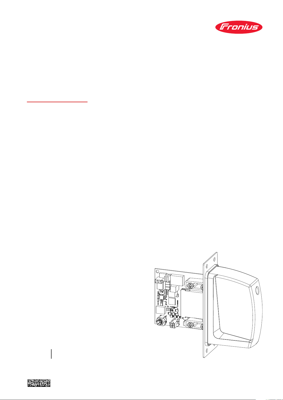
Device Concept The robot interface serves as an interface between the power source and stand-
ardized bus modules supporting a wide range of communication protocols.
Fronius may factory-fit the robot interface in the power source but it can also be
retrofitted by appropriately trained and qualified personnel.
(1) Robot control system
(2) SpeedNet data cable
(3) Robot interface
5

Block Diagram
Spider NT241
RI FB/i IGM V1.0
Data
24 V
Module
(1)
(2)
(3)
(4) Power source
(5) Cooling unit
(6) Interconnecting hosepack
(7) Wirefeeder
(8) Robot
Scope of Supply
Required Tools
and Materials
Screwdriver TX8
-
Screwdriver TX20
-
Screwdriver TX25
-
Diagonal cutting pliers
-
(1) RI FB/i IGM V1.0
(2) Data cable
4-pin
(3) Cable ties
(4) These Operating Instructions
(not pictured)
Installation Requirements
The robot interface may only be installed in the designated opening on the rear
of the power source.
6
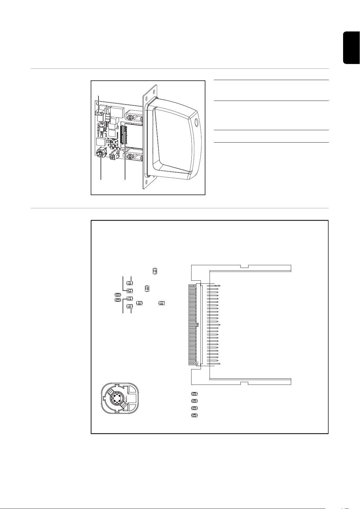
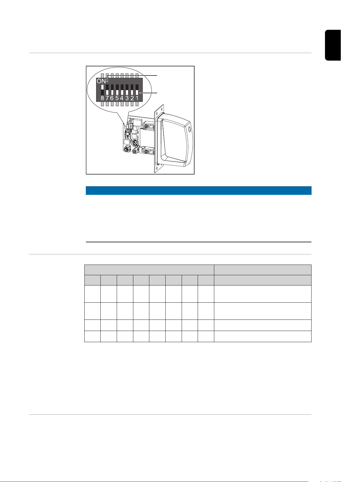
Connection Sockets and Indicators on the Robot
(2) (3)
(1)
(14)
(13)
(12)
(11)
(2)
(1)
(9)
(10)
(8)
(7)
(3) (4)
(5) (6)
Interface
Connections on
the Robot Interface
LEDs on Robot
Interface PCB
EN-US
(1) Power supply connection
2-pin
(2) SpeedNet data cableconnec-
tion
4-pin
(3) Bus module connection
7

(1) ETH1 LED Green For diagnosing the network connec-
tion.
(2) ETH2 LED Orange
For details, see section below titled
"LEDs for Network Connection Diagnosis"
(3) LED 3 Green
(4) LED 4 Green
(5) LED 5 Green
(6) LED 6 Red
(7) +3V3 LED Green For diagnosing the power supply.
(8) +24V LED Green
(9) DIG OUT 2 LED Green
(10) DIG OUT 1 LED Green
(11) LED 11 Green
No function
Flashes at 4 Hz = No SpeedNet
-
connection
Flashes at 20 Hz = Establishing
-
SpeedNet connection
Flashes at 1 Hz = SpeedNet con-
-
nection established
Lights up when an internal error occurs.
Remedy: Restart the robot interface.
If this does not resolve the issue, inform the service team.
For details, see section below titled
"LEDs for Power Supply Diagnosis"
Digital output 2. LED lights up when
active
Digital output 1. LED lights up when
active
LEDs for Power
Supply Diagnosis
(12) LED 12 Green
(13) LED 13 Green
(14) LED 14 Green
LED Indicat-orMeaning Cause
Off
+24V
Lights up
Off
+3V3
Lights up
No supply voltage available
for interface
24 VDC supply voltage
present on robot interface
No operating voltage
present on robot interface
3 VDC operating voltage
present on robot interface
No function
Robot interface power
-
supply not established
Power supply cable
-
faulty
24 VDC supply voltage
-
not present
Robot interface power
-
supply unit is faulty
8

LEDs for Network Connection
Diagnosis
LED Indicat-orMeaning Cause
No network connection
-
established for interface
Network cable faulty
-
ETH1
Off No network connection
Lights up
Flashes Data transfer in progress
Network connection established
EN-US
ETH2
Off
Lights up
Transmission speed
10 Mbit/s
Transmission speed
100 Mbit/s
9
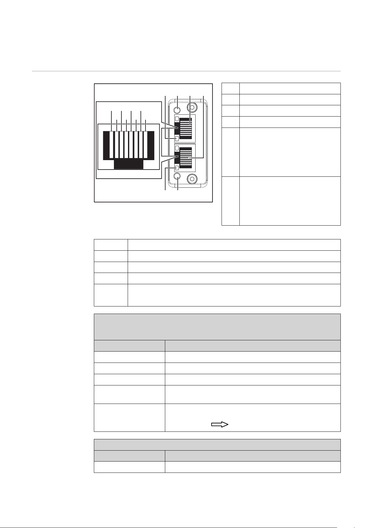
Connections and Indicators on the Bus Module -
(12)(11)(10)
(14)(13)
(9)
(1)
(2)
(3)
(4)
(5)
(6)
(7)
(8)
EtherCAT
Connections and
Indicators
(1) TX+
(2) TX-
(3) RX+
(6) RX-
(4),
Not normally used; to ensure
(5)
signal completeness, these
pins must be interconnected
and, after passing through a
filter circuit, must terminate at
the ground conductor (PE).
(7),
Not normally used; to ensure
(8)
signal completeness, these
pins must be interconnected
and, after passing through a
filter circuit, must terminate at
the ground conductor (PE).
(9) Connection/Activity LED - EtherCAToutput
(10) ERR LED (error)
(11) EtherCAToutput
(12) EtherCATinput
(13) Connection/Activity LED - EtherCATinput
(14) RUN LED (operation)
RUN LED (operation)
This indicates the status of the CoE communication.
(CoE = CANopen over EtherCAT)
Status Meaning
Off EtherCAT device in 'init' status (or no supply voltage)
Lights up green EtherCAT device in 'operational' status
Flashes green EtherCAT device in 'pre-operational' status
Flashes green
(briefly)
Lights up red If the Run LED and Error LED light up red, this indic-
ERR LED (error)
Status Meaning
EtherCAT device in 'safe-operational' status
ates a serious event which places the interface in an exception state. Contact the service team
10
Off No error (or no supply voltage)

ERR LED (error)
Status Meaning
Flashes red Incorrect configuration
The status change received from the master is not possible due to invalid register or object settings.
Flashes red (twice) Application watchdog timeout
Sync manager watchdog timeout
Lights up red Application controller failure
Anybus module in EXCEPTION
Connection/Activity LED
Status Meaning
Off No connection (or no supply voltage)
Lights up green Connection detected, no activity
Flickers green Connection detected, activity present
EN-US
11
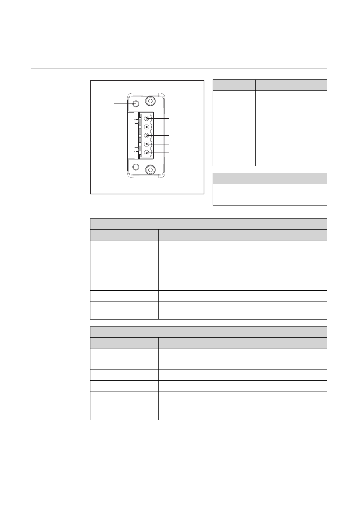
Connections and Indicators on the Bus Module -
(1)
(2)
(3)
(4)
(5)
(6)
(7)
DeviceNet
Connections and
Indicators
Pin Signal Description
(1) V - Supply voltage
(2) CAN_LCAN low bus line
(3) SHIELDCable shield
(4) CAN_HCAN high bus line
(5) V + Supply voltage
Indicators
(6) LED MS (Module Status)
(7) LED NS (Network Status)
LED MS (Module Status)
Status Meaning
Off No supply voltage
Lights up green Normal operation
Flashes green Missing or incomplete configuration, commissioning re-
quired
Lights up red Non-correctable error
Flashes red Correctable error
Alternates between
red and green
LED NS (Network Status)
Status Meaning
Off Not online or no supply voltage
Lights up green Online, one or more connections established
Flashes green Online, no connections established
Lights up red Critical connection error
Flashes red Timeout for one or more of the connections
Alternates between
red and green
Self-test is running
Self-test is running
12

Technical Data EtherCAT
EN-US
Environmental
Conditions
Robot Interface
Technical Data
CAUTION!
A risk is posed by prohibited environmental conditions.
This can result in severe damage to equipment.
Only store and operate the device under the following environmental condi-
▶
tions.
Temperature range of ambient air:
During operation: -10 °C to +40 °C (14 °F to 104 °F)
-
During transport and storage: -20 °C to +55 °C (-4 °F to 131 °F)
-
Relative humidity:
Up to 50% at 40 °C (104 °F)
-
Up to 90% at 20 °C (68 °F)
-
Ambient air: free of dust, acids, corrosive gases or substances, etc.
Altitude above sea level: up to 2000 m (6500 ft).
Power supply Internal (24 V)
Degree of protection IP 23
Data Transfer
Properties
Configuration
Parameters
Transfer technology:
EtherCAT
Medium:
When selecting the cable, plug, and terminating resistors, the IEC 61784‑5‑12
for the planning and installation of EtherCAT systems must be observed.
The EMC tests were carried out by the manufacturer with an original Beckhoff
cable (ZK1090-9191-xxxx).
Transmission speed:
100 Mbit/s
Bus connection:
RJ45 Ethernet
Application layer:
CANopen
In some robot control systems, it may be necessary to state the configuration
parameters described here so that the bus module can communicate with the robot.
13

Parameters Value Description
Vendor ID 0000 02C1
Product Code 0001 0341
(66369
dec
)
hex
hex
(705
dec
Device name Fronius FB-IGM-1-0-
EtherCAT
) Fronius International GmbH
Standard image
Fronius-FB-Inside-EtherCAT
14

Technical Data DeviceNet
EN-US
Environmental
Conditions
Robot Interface
Technical Data
CAUTION!
A risk is posed by prohibited environmental conditions.
This can result in severe damage to equipment.
Only store and operate the device under the following environmental condi-
▶
tions.
Temperature range of ambient air:
During operation: -10 °C to +40 °C (14 °F to 104 °F)
-
During transport and storage: -20 °C to +55 °C (-4 °F to 131 °F)
-
Relative humidity:
Up to 50% at 40 °C (104 °F)
-
Up to 90% at 20 °C (68 °F)
-
Ambient air: free of dust, acids, corrosive gases or substances, etc.
Altitude above sea level: up to 2000 m (6500 ft).
Power supply Internal (24 V)
Degree of protection IP 23
Data Transfer
Properties
Configuration
Parameters
Network topology
Linear bus, bus termination on both ends (121 Ohm), stub cables are possible
Medium and maximum bus length
When selecting the cable, plug, and terminating resistors, the ODVA recommendation for the planning and installation of DeviceNet systems must be observed
Number of stations
Max. 64 participants
Transmission speed
500 kbit/s, 250 kbit/s, 125 kbit/s
Process data width
Can be configured in the robot interface
see following section "Configuration of robot interface"
In some robot control systems, it may be necessary to state the configuration
parameters described here so that the bus module can communicate with the robot.
Parameters Value Description
Vendor ID 0534
hex
(1332
) Fronius International GmbH
dec
15

Parameters Value Description
Device Type 000C
Product Code 0440
hex
hex
(12
dec
(1088
) Communication adapter
) Fronius FB IGM 1.0 DeviceNet
dec
Product Name Fronius FB-IGM-1-0-DeviceNet
16
Configuring the Robot Interface - EtherCAT
(1)
(2)
EN-US
Function of the
Dip Switch on
the Interface
The dip switch on the robot interface
is used to set the process image
(standard image).
Default setting for process image:
Positions 7 and 8 of DIP switch set
to OFF (1) = standard image = IGM
V1.0
NOTE!
Risk due to non-effective DIP switch setting.
This may result in malfunctions.
Every time you change the DIP switch settings, re-start the interface after-
▶
wards. This is essential for the changes to take effect.
Interface re-start = disconnect and reconnect the power supply or execute
▶
the corresponding function on the power source website (SmartManager).
Setting the Process Data Width
Assigning the
EtherCAT Address
Dip switch
8 7 6 5 4 3 2 1 Configuration
OFF OFF
OFF ON
ON OFF
ON ON
The process data width defines the scope of the transferred data volume.
The kind of data volume that can be transferred depends on
the robot controls
-
the number of power sources
-
the type of power sources
-
-
-
The EtherCAT address is assigned by the master.
- - - - - - IGM image
832 Bit
- - - - - - Fronius standard image
320 Bit
- - - - - - Not used
- - - - - - Not used
"Intelligent Revolution"
"Digital Revolution" (Retro Fit)
17

Configuring the Robot Interface - DeviceNet
(1)
(2)
Function of the
Dip Switch on
the Interface
The dip switch on the robot interface is
used to configure:
the process data width
-
the node address
-
NOTE!
Risk due to non-effective DIP switch setting.
This may result in malfunctions.
Every time you change the DIP switch settings, re-start the interface after-
▶
wards. This is essential for the changes to take effect.
Interface re-start = disconnect and reconnect the power supply or execute
▶
the corresponding function on the power source website (SmartManager).
Setting the Process Data Width
Dip switch
8 7 6 5 4 3 2 1 Configuration
OFF OFF
OFF ON
ON OFF
ON ON
The process data width defines the scope of the transferred data volume.
The kind of data volume that can be transferred depends on
the robot controls
-
the number of power sources
-
the type of power sources
-
-
-
- - - - - - Not used
- - - - - - Fronius standard image
320 Bit
- - - - - - Not used
- - - - - - Fronius Retro Fit image
96 Bit
"Intelligent Revolution"
"Digital Revolution" (Retro Fit)
18

Set node address with dip
switch
(example)
Dip switch
8 7 6 5 4 3 2 1 Node address
- -
OFF OFF OFF OFF OFF ON
1
EN-US
- -
- -
- -
- -
OFF OFF OFF OFF ON OFF
OFF OFF OFF OFF ON ON
ON ON ON ON ON OFF
ON ON ON ON ON ON
2
3
62
63
The node address is set with positions 1 to 6 of the dip switch.
The configuration is carried out in binary format. This results in a configuration
range of 1 to 63 in decimal format.
19

Configuring the
3
2
1
4
xx.x.xxx.x
1.9.0-16501.9508
Node Address
Upon delivery the configured node address is 0.
The node address can be configured in two ways:
Node addresses in the range of 1 to 63 can be configured with the dip switch.
-
In this case, a node address previously configured by a configuration tool is
overwritten.
For more information about the dip switch see Function of the Dip
-
Switch on the Interface on page 18.
If configurations have already been made, the network configurations can be restored to factory settings in two ways:
set all dip switches back to 0 and restart interface
-
or
with the button Restore factory settings on the website of the power source
-
(SmartManager)
The Website of
the Power
Source
Opening and
Logging into the
SmartManager
for the Power
Source
The power source has its own website, the SmartManager.
As soon as the power source has been integrated into a network, the SmartManager can be opened via the IP address of the power source.
Depending on the system configuration and software upgrades, the SmartManager may contain the following entries:
Overview
-
Update
-
Screenshot
-
Save and restore
-
Function packages
-
Job data
-
Overview of characteristics
-
RI FB INSIDE/i
-
Presettings/System/Information ==> note down IP address of power source
1
Enter the IP address into the search field of the browser
2
Enter username and password
3
Factory setting:
Username = admin
Password = admin
Confirm displayed message
4
The SmartManager of the power source is displayed.
20

Installing the Robot Interface
EN-US
Safety
Preparation
WARNING!
Electrical current hazard.
This can result in serious injuries or death.
Before starting work, switch off all the devices and components involved and
▶
disconnect them from the grid.
Secure all the devices and components involved to prevent unintentional re-
▶
starting.
After opening the device, use a suitable measuring instrument to check that
▶
electrically charged components (such as capacitors) have been discharged.
WARNING!
Electrical current hazard caused by an inadequate ground conductor connection.
This can result in severe personal injury and damage to property.
Always use the original housing screws in the original quantity.
▶
1 2
3 4
21

5
Routing the Data
Cable
1 2
3
22

Installing the
Robot Interface
1 2
EN-US
Final Tasks
1 2
23

Installing the Bus Module
Safety
Installing the
Bus Module
WARNING!
Danger from electrical current.
Serious injuries or death may result.
Before starting work, switch off all devices and components involved, and
▶
disconnect them from the grid.
Secure all devices and components involved so that they cannot be switched
▶
back on.
WARNING!
Danger from electrical current due to inadequate ground conductor connection.
Serious personal injury and property damage may result.
Always use the original housing screws in the quantity initially supplied.
▶
1 2
24
3

Input and Output Signals Standard Image IGM
V1.0 - EtherCat
Data types The following data types are used:
UINT16 (Unsigned Integer)
-
Whole number in the range from 0 to 65535
SINT16 (Signed Integer)
-
Whole number in the range from -32768 to 32767
Conversion examples:
for a positive value (SINT16)
-
e.g. desired wire speed x factor
Availability of input signals
12.3 m/min x 100 = 1230
for a negative value (SINT16)
-
e.g. arc correction x factor
-6.4 x 10 = -64
The input signals listed below are available from firmware V3.2.30 of the TPS/i
power source.
= FFC0
dec
= 04CE
dec
hex
EN-US
hex
Input signals
(from robot to
power source)
25

Address
Relative Absolute
WORD
0
BYTE
0
1
BIT
BIT
0 0 Welding Start
1 1 Robot ready High
2 2 Working mode Bit 0 High
3 3 Working mode Bit 1 High
4 4 Working mode Bit 2 High
5 5 Working mode Bit 3 High
6 6 Working mode Bit 4 High
7 7 —
0 8 Gas on
1 9 Wire forward
2 10 Wire backward
3 11 Error quit
Signal
Activity /
data type Range
Increas-
ing
See table Value range
for Working mode on
Increas-
ing
Increas-
ing
Increas-
ing
Increas-
ing
page 33
Factor
4 12 Touch sensing High
5 13 Torch blow out
6 14 Process line selection Bit 0 High
7 15 Process line selection Bit 1 High
Increas-
ing
26

Address
Relative Absolute
BIT
WORD
BYTE
BIT
0 16 Welding Simulation High
1 17 Synchro pulse on High
2 18 SFI on High
Signal
Activity /
data type Range
EN-US
Factor
2
1
3
3 19 —
4 20 —
5 21 —
6 22 Wire brake on High
7 23 Torchbody Xchange High
0 24 —
1 25 Teach mode High
2 26 —
3 27 —
4 28 —
5 29 Wire sense start
6 30 Wire sense break
7 31 —
0 32 TWIN mode bit 0 High See table Value Range
1 33 TWIN mode bit 1 High
Increas-
ing
Increas-
ing
for TWIN Mode on
page 33
2 34 —
3 35 —
4
2
5
4 36 —
See table Value Range
5 37 Documentation mode High
6 38 —
7 39 —
0 40 —
1 41 —
2 42 —
3 43 —
4 44 —
5 45 —
6 46 —
7 47
Disable process controlled correction
High
for Documentation
Mode on page 33
27

Address
Relative Absolute
WORD
3
BYTE
6
7
BIT
BIT
0 48 —
1 49 —
2 50 —
3 51 —
4 52 —
5 53 —
6 54 —
7 55 —
0 56 ExtInput1 => OPT_Output 1 High
1 57 ExtInput2 => OPT_Output 2 High
2 58 ExtInput3 => OPT_Output 3 High
3 59 ExtInput4 => OPT_Output 4 High
4 60 ExtInput5 => OPT_Output 5 High
5 61 ExtInput6 => OPT_Output 6 High
6 62 ExtInput7 => OPT_Output 7 High
Signal
Activity /
data type Range
Factor
8 0–7 64–71
4
9 0–7 72–79
10,
5
0–7 80–95
11
7 63 ExtInput8 => OPT_Output 8 High
Welding characteristic- / Job
number
For the welding processes
MIG/MAG pulse synergic,
MIG/MAG standard synergic,
MIG/MAG standard manual,
MIG/MAG PMC,
MIG/MAG LSC,
CMT, ConstantWire:
Wire feed speed command
value
For job mode:
Power correction
UINT16 0 to 1000 1
-327.68 to
SINT16
SINT16
327.67
[m/min]
-20.00 to 20.00
[%]
100
100
28

Address
Relative Absolute
BIT
WORD
BYTE
BIT
Signal
For the welding processes
MIG/MAG pulse synergic,
MIG/MAG standard synergic,
MIG/MAG PMC,
MIG/MAG LSC,
CMT:
Arclength correction
Activity /
data type Range
SINT16
-10.0 to 10.0
[steps]
EN-US
Factor
10
12,
6
7
0–7 96–111
13
14,
0–7 112–127
15
For the welding process
MIG/MAG standard manual:
Welding voltage
For job mode:
Arclength correction
For the welding process ConstantWire:
Hotwire current
For the welding processes
MIG/MAG pulse synergic,
MIG/MAG standard synergic,
MIG/MAG PMC,
MIG/MAG LSC,
CMT:
Pulse-/dynamic correction
For the welding process
MIG/MAG standard manual:
Dynamic
UINT16
SINT16
UINT16
SINT16
UINT16
0.0 to 6553.5
[V]
-10.0 to 10.0
[steps]
0.0 to 6553.5
[A]
-10.0 to 10.0
[steps]
0.0 to 10.0
[steps]
10
10
10
10
10
16 0–7 128–135
8
17 0–7 136–143
18 0–7 144–151
9
19 0–7 152–159
20 0–7 160–167
10
21 0–7 168–175
22 0–7 176–183
11
23 0–7 184–191
24 0–7 192–199
12
25 0–7 200–207
26 0–7 208–215
13
27 0–7 216–223
Wire retract correction UINT16 0.0 to 10.0 10
Welding speed UINT 16
Process controlled correction
—
—
—
0 to 1000
[cm/min]
See table Value range
for Process controlled
correction on page 34
10
29

Address
Relative Absolute
WORD
BYTE
28 0–7 224–231
14
29 0–7 232–239
30 0–7 240–247
15
31 0–7 248–255
32 0–7 256–263
16
33 0–7 264–271
34 0–7 272–279
17
35 0–7 280–287
36 0–7 288–295
18
37 0–7 296–303
38 0–7 304–311
19
39 0–7 312–319
0 320 Disable Start-End-Parameter High
1 321 Disable SFI-Parameter High
2 322 Disable SP-Parameter High
BIT
BIT
Activity /
Signal
—
Wire forward / backward length UINT16
Wire sense edge detection UINT16
—
—
Seam number UINT16 0 to 65,535 1
data type Range
OFF / 1 to
65535
[mm]
OFF / 0.5 to 20
[mm]
10
Factor
1
20
40
41
3 323 Disable Process-Mix-Parameter High
4 324 Disable gas-settings High
5 325 Disable delaytime flowsensor High
6 326 Disable inching value High
7 327
0 328 Enable TWIN-Parameter High
1 329 —
2 330 —
3 331 —
4 332 —
5 333 —
6 334 —
7 335 —
Disable process controlled correction 2
High
30

Address
Relative Absolute
BIT
WORD
BYTE
BIT
0 336 Enable resistance overwrite High
1 337 Set resistance value High
2 338 Enable inductance overwrite High
Signal
Activity /
data type Range
EN-US
Factor
21
42
43
3 339 Set inductance value High
4 340 —
5 341 —
6 342 —
7 343 —
0 344
1 345
2 346
3 347
4 348
5 349 —
6 350 —
7 351 —
Cooling unit operating mode
Bit 0
Cooling unit operating mode
Bit 1
Cooling unit operating mode
Bit 2
Pulse synchronization ratio Bit
0
Pulse synchronization ratio Bit
1
High
See table Value Range
High
High
High
High
for Cooling Unit Oper-
ating Mode on page
34
44 0–7 352–359
22
45 0–7 360–367
46 0–7 368–375
23
47 0–7 376–383
48 0–7 384–391
24
49 0–7 392–399
50 0–7 400–407
25
51 0–7 408–415
52 0–7 416–423
26
53 0–7 424–431
54 0–7 432–439
27
55 0–7 440–447
56 0–7 448–455
28
57 0–7 456–463
58 0–7 464–471
29
59 0–7 472–479
Gas preflow UINT 16
Gas postflow UINT 16
Inching Value SINT 16
Delay time flow sensor UINT 16
Gas Command Value UINT 16
Gas factor UINT 16
Ignition time out UINT 16
S2T-Starting current UINT 16
0 to 9.9
[s]
0 to 60.0
[s]
0.5 to 25
[m/min]
5 to 25
[steps of 5]
0.5 to 30.0
[l/min]
0.9 to 20.0
[l/min]
5 to 100
[steps]
0 to 200
[%]
10
10
100
1
10
100
1
1
31

Address
Relative Absolute
WORD
BYTE
60 0–7 480–487
30
61 0–7 488–495
62 0–7 496–503
31
63 0–7 504–511
64 0–7 512–519
32
65 0–7 520–527
66 0–7 528–535
33
67 0–7 536–543
68 0–7 544–551
34
69 0–7 552–559
70 0–7 560–567
35
71 0–7 568–575
72 0–7 576–583
36
73 0–7 584–591
BIT
BIT
Activity /
Signal
S2T-Starting current time UINT 16
S2T Slope 1 UINT 16
S2T Slope 2 UINT 16
S2T End current UINT 16
S2T End current time UINT 16
S2T Start Arclength correction SINT 16 -10 to +10 10
S2T End Arclength correction SINT 16 -10 to +10 10
data type Range
Off (0.0) /
0.1 to 10.0
[s]
0 to 9.9
[s]
0 to 9.9
[s]
0 to 200
[%]
Off (0.0) /
0.1 to 10.0
[s]
10
10
10
1
10
Factor
74 0–7 592–599
37
75 0–7 600–607
76 0–7 608–615
38
77 0–7 616–623
78 0–7 624–631
39
79 0–7 632–639
80 0–7 640–647
40
81 0–7 648–655
82 0–7 656–663
41
83 0–7 664–671
84 0–7 672–679
42
85 0–7 680–687
86 0–7 688–695
43
87 0–7 696–703
88 0–7 704–711
44
89 0–7 712–719
Off (0.0) /
SFI Hotstart UINT 16
SP Delta wire feed UINT 16 0.1 to 6 10
SP Frequency UINT 16 0.5 to 3 10
SP Duty Cycle UINT 16 10 to 90 1
SP Arc length correction high SINT 16 -10 to +10 10
SP Arc length correction low SINT 16 -10 to +10 10
Process-Mix High power time
correction
Process-Mix Low power time
correction
SINT 16 -10 to +10 10
SINT 16 -10 to +10 10
0.01 to 2.00
[s]
100
32
90 0–7 720–727
45
91 0–7 728–735
92 0–7 736–743
46
93 0–7 744–751
Process-Mix Low power correction
Process controlled correction 2
SINT 16 -10 to +10 10
See table Value range
for Process controlled
correction 2 on page
34

Address
Relative Absolute
BIT
WORD
BYTE
BIT
Signal
94 0–7 752–759 Phase shift Lead/Trail UINT 8
47
95 0–7 760–767 Ignition delay Trail UINT 8
96 0–7 768–775
48
—
97 0–7 776–783
98 0–7 784–791
49
—
99 0–7 792–799
Activity /
data type Range
Auto / 0 to 95
[%]
Auto / Off /
0.00 to 2.00 [s]
EN-US
Factor
100 0–7 800–807
50
101 0–7 808–815
102 0–7 816–823
51
103 0–7 824–831
Value range for
Working mode
Resistance UINT 16
Inductance UINT 16
0 to +400
[mOhm]
0 to +250
[microhenries]
Bit 4 Bit 3 Bit 2 Bit 1 Bit 0 Description
0 0 0 0 0 Internal parameter selection
0 0 0 0 1 Special 2-step mode characteristics
0 0 0 1 0 Job mode
0 1 0 0 0 2-step mode characteristics
1 1 0 0 0 R/L measurement
1 1 0 0 1 R/L alignment
Value range for operating mode
10
10
Value Range for
TWIN Mode
Value Range for
Documentation
Mode
Bit 1 Bit 0 Description
0 0 TWIN Single mode
0 1 TWIN Lead mode
1 0 TWIN Trail mode
1 1 Reserved
Value range for TWIN mode
Bit 0 Description
0 Seam number of power source (internal)
33

Value range for
Process controlled correction
Bit 0 Description
1 Seam number of robot (Word 19)
Value range for documentation mode
Process
Signal
PMC Arc length stabilizer SINT16
Value range for process-dependent correction
Activity /
Value range
configuration range
data type
-3276.8 to +3276.7
0.0 to +5.0 Volts 10
Unit
Factor
Value Range for
Cooling Unit Operating Mode
Value range for
Process controlled correction 2
Bit 2 Bit 1 Bit 0 Description
0 0 0 auto
0 0 1 eco
0 1 0 on
0 0 0 off
Value Range for Cooling Unit Operating Mode
Process
Signal
Activity /
data type
PMC Penetration stabilizer SINT16
Value range for process-dependent correction 2
Value range
configuration
range
Unit
-3276.8 to +3276.7
0.0 to +10.0 m/min 10
Factor
34

Availability of
the output signals
Output signals
(from power
source to robot)
Address
Relative Absolute
The output signals listed below are available from firmware V3.2.30 of the TPS/i
power source.
EN-US
WORD
0
BYTE
0
1
BIT
BIT
0 0 Heartbeat Powersource
1 1 Power source ready High
2 2 Warning High
3 3 Process active High
4 4 Current flow High
5 5 Arc stable- / touch signal High
6 6 Main current signal High
7 7 Touch signal High
0 8 Collisionbox active Low
1 9 Robot Motion Release High
2 10 Wire stick workpiece High
3 11 —
4 12 Short circuit contact tip High
5 13 Parameter selection internally High
Signal
Activity /
data type Range
High /
Low
1 Hz
0 = collision or
cable break
Factor
6 14 Characteristic number valid High
7 15 Torch body gripped High
35

Address
Relative Absolute
WORD
1
BYTE
2
3
BIT
BIT
0 16 Command value out of range High
1 17 Correction out of range High
2 18 —
3 19 Limit Signal High
4 20 —
5 21 —
6 22 Main supply status Low
7 23 —
0 24 Sensor status 1 High
1 25 Sensor status 2 High
2 26 Sensor status 3 High
3 27 Sensor status 4 High
4 28 —
5 29 —
6 30 —
Signal
Activity /
data type Range
See table Assignment
of Sensor Statuses 1–
4 on page 40
Factor
7 31 —
0 32 Function status Bit 0 High See table Value Range
1 33 Function status Bit 1 High
2 34 —
4
2
5
3 35 Safety status Bit 0 High See table Value range
4 36 Safety status Bit 1 High
5 37 —
6 38 Notification High
7 39 System not ready High
0 40 —
1 41 —
2 42 —
3 43 —
4 44 —
5 45 —
6 46 —
for Function status on
page 40
Safety status on page
41
36
7 47 —

Address
Relative Absolute
BIT
WORD
BYTE
BIT
0 48 Process Bit 0 High
Signal
Activity /
data type Range
EN-US
Factor
6
3
7
8 0–7 64–71
4
9 0–7 72–79
1 49 Process Bit 1 High
2 50 Process Bit 2 High
3 51 Process Bit 3 High
4 52 Process Bit 4 High
5 53 —
6 54 Gas nozzle touched High
7 55 TWIN synchronisation active High
0 56 ExtOutput1 <= OPT_Input1 High
1 57 ExtOutput2 <= OPT_Input2 High
2 58 ExtOutput3 <= OPT_Input3 High
3 59 ExtOutput4 <= OPT_Input4 High
4 60 ExtOutput5 <= OPT_Input5 High
5 61 ExtOutput6 <= OPT_Input6 High
6 62 ExtOutput7 <= OPT_Input7 High
7 63 ExtOutput8 <= OPT_Input8 High
Welding voltage UINT16
See table Value Range
for Process Bit on page
41
0.0 to 655.35
[V]
100
10 0–7 80–87
5
11 0–7 88–95
12 0–7 96–103
6
13 0–7 104–111
14 0–7 112–119
7
15 0–7 120–127
16 0–7 128–135
8
17 0–7 136–143
18 0–7 144–151
9
19 0–7 152–159
20 0–7 160–167
10
21 0–7 168–175
22 0–7 176–183
11
23 0–7 184–191
24 0–7 192–199
12
25 0–7 200–207
26 0–7 208–215
13
27 0–7 216–223
Welding current UINT16
Wire feed speed SINT16
Actual real value for seam
tracking
Error number UINT16 0 to 65,535 1
Warning number UINT16 0 to 65,535 1
Motor current M1 SINT16
Motor current M2 SINT16
Motor current M3 SINT16
—
UINT16 0 to 6.5535
0.0 to 6553.5
[A]
-327.68 to
327.67 [m/min]
-327.68 to
327.67 [A]
-327.68 to
327.67 [A]
-327.68 to
327.67 [A]
10
100
1000
100
100
100
0
37

Address
Relative Absolute
WORD
BYTE
28 0–7 224–231
14
29 0–7 232–239
30 0–7 240–247
15
31 0–7 248–255
32 0–7 256–263
16
33 0–7 264–271
34 0–7 272–279
17
35 0–7 280–287
36 0–7 288–295
18
37 0–7 296–303
38 0–7 304–311
19
39 0–7 312–319
0 320 Gas process line 1 pushed High
1 321 —
2 322 Wire feeder 1 available High
BIT
BIT
Activity /
Signal
—
—
Wire position SINT16
—
—
—
data type Range
-327.68 to
327.67 [A]
100
Factor
40
3 323 Wire feeder 2 available High
4 324 Wire feeder 3 available High
5 325 Gas controller available High
6 326 —
7 327 —
20
0 328 OPT/i Safety Stop available High
1 329 —
2 330 —
3 331 —
41
4 332 —
5 333 —
6 334 —
7 335 —
42 0–7 336–343
21
43 0–7 344–351
44 0–7 352–359
22
45 0–7 360–367
—
Cooler temperature SINT16
-100 to +200
[°C]
10
38
46 0–7 368–375
23
47 0–7 376–383
48 0–7 384–391
24
49 0–7 392–399
Cooler flow rate SINT16
Real energy actual value UINT16
-100 to +100
[l/min]
0 to 6553.5
[kJ]
100
10

Address
Relative Absolute
BIT
WORD
BYTE
50 0–7 400–407
25
51 0–7 408–415
52 0–7 416–423
26
53 0–7 424–431
54 0–7 432–439
27
55 0–7 440–447
56 0–7 448–455
28
57 0–7 456–463
58 0–7 464–471
29
59 0–7 472–479
60 0–7 480–487
30
61 0–7 488–495
BIT
Activity /
Signal
Power value UINT16
Hour meter power on UINT32
Hour meter current flow UINT32
—
data type Range
0 to 6553.5
[kW]
0 to 100,000
[h]
0 to 100,000
[h]
10
10
10
EN-US
Factor
62 0–7 496–503
31
63 0–7 504–511
64 0–7 512–519
32
65 0–7 520–527
66 0–7 528–535
33
67 0–7 536–543
68 0–7 544–551
34
69 0–7 552–559
70 0–7 560–567
35
71 0–7 568–575
72 0–7 576–583
36
73 0–7 584–591
74 0–7 592–599
37
75 0–7 600–607
76 0–7 608–615
38
77 0–7 616–623
78 0–7 624–631
39
79 0–7 632–639
—
Real value welding voltage UINT16
Real value welding current UINT16
Real value wire feed speed SINT16
MIG gas real value UINT16 0.0 to 100.0 10
Feeder inching speed SINT16
—
—
—
0.0 to 655.35
[V]
0.0 to 6553.5
[A]
-327.68 to
327.67 [m/min]
-327.68 to
327.67
100
10
100
100
80 0–7 640–647
40
81 0–7 648–655
82 0–7 656–663
41
83 0–7 664–671
84 0–7 672–679
42
85 0–7 680–687
—
—
—
39

Address
Relative Absolute
WORD
BYTE
BIT
86 0–7 688–695
43
87 0–7 696–703
88 0–7 704–711
44
89 0–7 712–719
90 0–7 720–727
45
91 0–7 728–735
92 0–7 736–743
46
93 0–7 744–751
94 0–7 752–759
47
95 0–7 760–767
96 0–7 768–775
48
97 0–7 776–783
98 0–7 784–791
49
99 0–7 792–799
100 0–7 800–807
50
101 0–7 808–815
BIT
Activity /
Signal
data type Range
—
—
—
—
—
—
—
Resistance UINT 16
0 to +400
[mOhm]
10
Factor
102 0–7 816–823
51
103 0–7 824–831
Assignment of
Sensor Statuses
1–4
Value Range for
Function status
Inductance UINT 16
0 to +250
[microhenries]
Signal Description
Sensor status 1 OPT/i WF R wire end (4,100,869)
Sensor status 2 OPT/i WF R wire drum (4,100,879)
Sensor status 3 OPT/i WF R ring sensor (4,100,878)
Sensor status 4 Wire buffer set CMT TPS/i (4,001,763)
Bit 1 Bit 0 Description
0 0 inactive
0 1 idle
1 0 finished
10
40
1 1 Error
Value range for function status

Value range
Safety status
Bit 1 Bit 0 Description
0 0 Reserve
0 1 Hold
1 0 Stop
1 1 Not installed / active
EN-US
Value Range for
Process Bit
Bit 4 Bit 3 Bit 2 Bit 1 Bit 0 Description
0 0 0 0 0 No internal parameter selection or
process
0 0 0 0 1 MIG/MAG pulse synergic
0 0 0 1 0 MIG/MAG standard synergic
0 0 0 1 1 MIG/MAG PMC
0 0 1 0 0 MIG/MAG LSC
0 0 1 0 1 MIG/MAG standard manual
0 0 1 1 0 Electrode
0 0 1 1 1 TIG
0 1 0 0 0 CMT
0 1 0 0 1 ConstantWire
41

Input and Output Signals - DeviceNet
Data types The following data types are used:
UINT16 (Unsigned Integer)
-
Whole number in the range from 0 to 65535
SINT16 (Signed Integer)
-
Whole number in the range from -32768 to 32767
Conversion examples:
for a positive value (SINT16)
-
e.g. desired wire speed x factor
12.3 m/min x 100 = 1230
for a negative value (SINT16)
-
e.g. arc correction x factor
-6.4 x 10 = -64
= FFC0
dec
= 04CE
dec
hex
hex
Availability of input signals
Input signals
(from robot to
power source)
The input signals listed below are available from firmware V3.2.30 of the TPS/i
power source.
42

Address
Process
image
Relative
WORD
0
Abso-
lute
BIT
BIT
BYTE
0 0 Welding Start
1 1 Robot ready High
2 2 Working mode Bit 0 High
3 3 Working mode Bit 1 High
0
4 4 Working mode Bit 2 High
5 5 Working mode Bit 3 High
6 6 Working mode Bit 4 High
7 7 —
0 8 Gas on
1 9 Wire forward
2 10 Wire backward
Signal
Activity /
data type
Increas-
ing
Increas-
ing
Increas-
ing
Increas-
ing
See table Value
Range for Work-
Range
ing Mode on
page 48
Factor
Standard
ü ü
EN-US
Economy
3 11 Error quit
1
4 12 Touch sensing High
5 13 Torch blow out
6 14 Processline selection Bit 0 High See table Value
7 15 Processline selection Bit 1 High
Increas-
ing
Increas-
ing
range Process
line selection on
page 49
43

Address
Relative
Process
image
Abso-
lute
WORD
1
BIT
BIT
BYTE
0 16 Welding Simulation High
1 17 Synchro pulse on High
2 18 —
3 19 —
2
4 20 —
5 21 —
6 22 Wire brake on High
7 23 Torchbody Xchange High
0 24 —
1 25 Teach mode High
2 26 —
3 27 —
4 28 —
3
5 29 Wire sense start
6 30 Wire sense break
Signal
Activity /
data type
Increas-
ing
Increas-
ing
Range
Factor
Standard
ü ü
Economy
7 31 —
44

Address
Process
image
Relative
WORD
2
Abso-
lute
BIT
BIT
BYTE
0 32 TWIN mode Bit 0 High See table Value
1 33 TWIN mode Bit 1 High
2 34 —
3 35 —
4
4 36 —
5 37 Documentation mode High
6 38 —
7 39 —
0 40 —
1 41 —
Signal
Activity /
data type
Range
Range for TWIN
Mode on page
See table Value
Range for Documentation Mode
on page 49
49
Factor
Standard
ü ü
EN-US
Economy
2 42 —
3 43 —
5
4 44 —
5 45 —
6 46 —
7 47
Disable process controlled
correction
High
45

Address
Relative
Process
image
Abso-
lute
WORD
3
BIT
BIT
BYTE
0 48 —
1 49 —
2 50 —
3 51 —
6
4 52 —
5 53 —
6 54 —
7 55 —
0 56 ExtInput1 => OPT_Output 1 High
1 57 ExtInput2 => OPT_Output 2 High
2 58 ExtInput3 => OPT_Output 3 High
3 59 ExtInput4 => OPT_Output 4 High
7
4 60 ExtInput5 => OPT_Output 5 High
5 61 ExtInput6 => OPT_Output 6 High
6 62 ExtInput7 => OPT_Output 7 High
7 63 ExtInput8 => OPT_Output 8 High
Signal
Activity /
data type
Range
Factor
Standard
ü ü
Economy
8 0–7 64–71
4
9 0–7 72–79
10,
5
0–7 80–95
11
Welding characteristic- / Job
number
For the welding processes
MIG/MAG pulse synergic,
MIG/MAG standard synergic,
MIG/MAG standard manual,
MIG/MAG PMC,
MIG/MAG LSC,
CMT, ConstantWire:
Wire feed speed command
value
For job mode:
Power correction
UINT16 0 to 1000 1
-327.68 to
SINT16
SINT16
327.67
[m/min]
-20.00 to
20.00
[%]
100
100
ü ü
ü ü
46

Address
Process
image
Relative
WORD
12,
6
BYTE
BIT
0–7 96–111
13
Abso-
lute
BIT
Signal
For the welding processes
MIG/MAG pulse synergic,
MIG/MAG standard synergic,
MIG/MAG PMC,
MIG/MAG LSC,
CMT:
Arclength correction
For the welding process
MIG/MAG standard manual:
Welding voltage
For job mode:
Arclength correction
For the welding process ConstantWire:
Hotwire current
Activity /
data type
SINT16
UINT16
SINT16
UINT16
Range
-10.0 to
10.0
[steps]
0.0 to
6553.5
[V]
-10.0 to
10.0
[steps]
0.0 to
6553.5
[A]
10
10
10
10
Factor
Standard
ü ü
EN-US
Economy
7
8
9
10
14,
0–7 112–127
15
16 0–7
17 0–7
18 0–7
19 0–7
20 0–7
21 0–7
128–
135
136–
143
144–
151
152–
159
160–
167
168–
175
For the welding processes
MIG/MAG pulse synergic,
MIG/MAG standard synergic,
MIG/MAG PMC,
MIG/MAG LSC,
CMT:
Pulse-/dynamic correction
For the welding process
MIG/MAG standard manual:
Dynamic
Wire retract correction UINT16
Welding speed UINT16
Process controlled correction
SINT16
UINT16
-10.0 to
10.0
[steps]
0.0 to
10.0
[steps]
0.0 to
10.0
[steps]
0.0 to
1000.0
[cm/min]
See table Value
range for Pro-
cess controlled
correction on
page 49
10
10
10
10
ü ü
ü
ü
ü
47

Address
Relative
Process
image
Abso-
lute
WORD
11
12
13
14
15
BYTE
22 0–7
23 0–7
24 0–7
25 0–7
26 0–7
27 0–7
28 0–7
29 0–7
30 0–7
31 0–7
BIT
BIT
176–
183
184–
191
192–
199
200–
207
208–
215
216–
223
224–
231
232–
239
240–
247
248–
255
Signal
—
—
—
—
Wire forward / backward
length
Activity /
data type
UINT16
Range
OFF / 1 to
65535
[mm]
Factor
Standard
Economy
ü
ü
ü
ü
1
ü
32 0–7
16
33 0–7
34 0–7 272–279
17
35 0–7
36 0–7
18
37 0–7
38 0–7
19
39 0–7
Value Range for
Working Mode
256–
263
264–
271
280–
287
288–
295
296–
303
304–
311
312–
319
Bit 4 Bit 3 Bit 2 Bit 1 Bit 0 Description
Wire sense edge detection UINT16
—
—
Seam number UINT16
0 0 0 0 0 Internal parameter selection
OFF / 0.5
to 20.0
[mm]
0 to
65,535
10
1
ü
ü
ü
ü
48
0 0 0 0 1 Special 2-step mode characteristics

Bit 4 Bit 3 Bit 2 Bit 1 Bit 0 Description
0 0 0 1 0 Job mode
0 1 0 0 0 2-step mode characteristics
0 1 0 0 1 2-step MIG/MAG standard manual
1 0 0 0 1 Stop coolant pump
Value range for operating mode
EN-US
Value range Process line selection
Value Range for
TWIN Mode
Bit 1 Bit 0 Description
0 0 Process line 1 (default)
0 1 Process line 2
1 0 Process line 3
1 1 Reserved
Value range for process line selection
Bit 1 Bit 0 Description
0 0 TWIN Single mode
0 1 TWIN Lead mode
1 0 TWIN Trail mode
1 1 Reserved
Value range for TWIN mode
Value Range for
Documentation
Mode
Value range for
Process controlled correction
Bit 0 Description
0 Seam number of power source (internal)
1 Seam number of robot (Word 19)
Value range for documentation mode
Process
Signal
Activity /
data type
PMC Arc length stabilizer SINT16
Value range for process-dependent correction
Value range
configuration
range
Unit
-327.8 to +327.7
0.0 to +5.0 Volts 10
Factor
49

Availability of
the output signals
Output Signals
(from Power
Source to Robot)
Address
relative absolute
The output signals listed below are available from firmware V3.2.30 of the TPS/i
power source.
Process
image
WORD
0
BYTE
BIT
0 0 Heartbeat Powersource High/Low 1 Hz
1 1 Power source ready High
2 2 Warning High
3 3 Process active High
0
4 4 Current flow High
5 5 Arc stable- / touch signal High
6 6 Main current signal High
7 7 Touch signal High
0 8 Collisionbox active Low
1 9 Robot Motion Release High
2 10 Wire stick workpiece High
3 11 —
1
4 12 Short circuit contact tip High
5 13
BIT
Signal
Parameter selection internally
Activity /
data type
High
Range
0 = colli-
sion or
cable
break
Standard
Factor
ü ü
Economy
50
6 14
7 15 Torch body gripped High
Characteristic number
valid
High

Address
Process
image
relative absolute
WORD
BYTE
BIT
0 16
1 17 Correction out of range High
2 18 —
3 19 Limitsignal High
2
4 20 —
5 21 —
6 22 Main supply status Low
1
7 23 —
0 24 Sensor status 1 High
1 25 Sensor status 2 High
2 26 Sensor status 3 High
3 27 Sensor status 4 High
3
4 28 —
BIT
Signal
Command value out of
range
Activity /
data type
High
Range
See table Assign-
ment of Sensor
Statuses 1–4 on
page 53
Factor
Standard
ü ü
EN-US
Economy
5 29 —
6 30 —
7 31 —
0 32 —
1 33 —
2 34 —
3 35 Safety status Bit 0 High See table Value
4
4 36 Safety status Bit 1 High
5 37 —
6 38 Notification High
2
7 39 System not ready High
0 40 —
1 41 —
2 42 —
3 43 —
5
4 44 —
range Safety status
on page 53
ü ü
5 45 —
6 46 —
7 47 —
51

Address
relative absolute
Process
image
WORD
3
BYTE
BIT
0 48 Process Bit 0 High
1 49 Process Bit 1 High
2 50 Process Bit 2 High
3 51 Process Bit 3 High
6
4 52 Process Bit 4 High
5 53 —
6 54 Touch signal gas nozzle High
7 55
0 56
1 57
2 58
3 59
7
4 60
BIT
Signal
TWIN synchronization
active
ExtOutput1 <= OPT_Input1
ExtOutput2 <= OPT_Input2
ExtOutput3 <= OPT_Input3
ExtOutput4 <= OPT_Input4
ExtOutput5 <= OPT_Input5
Activity /
data type
High
High
High
High
High
High
Range
See table Value
Range for Process
Bit on page 54
Factor
Standard
ü ü
Economy
5 61
6 62
7 63
8 0-7 64-71
4
9 0-7 72-79
10 0-7 80-87
5
11 0-7 88-95
12 0-7 96-103
6
13 0-7 104-111
14 0-7 112-119
7
15 0-7 120-127
16 0-7 128-135
8
17 0-7 136-143
18 0-7 144-151
9
19 0-7 152-159
ExtOutput6 <= OPT_Input6
ExtOutput7 <= OPT_Input7
ExtOutput8 <= OPT_Input8
Welding voltage UINT16
Welding current UINT16
Wire feed speed SINT16
Actual real value for
seam tracking
Error number UINT16
Warning number UINT16
High
High
High
UINT16
0.0 to
655.35 [V]
0.0 to
6553.5 [A]
-327.68 to
327.67 [m/
min]
0 to
6.5535
0 to
65535
0 to
65535
100
10
100
10000
1
1
ü ü
ü ü
ü ü
ü ü
ü
ü
52

Address
Process
image
relative absolute
WORD
BYTE
BIT
20 0-7 160-167
10
21 0-7 168-175
22 0-7 176-183
11
23 0-7 184-191
24 0-7 192-199
12
25 0-7 200-207
26 0-7 208-215
13
27 0-7 216-223
28 0-7 224-231
14
29 0-7 232-239
30 0-7 240-247
15
31 0-7 248-255
32 0-7 256-263
16
33 0-7 264-271
BIT
Signal
Motor current M1 SINT16
Motor current M2 SINT16
Motor current M3 SINT16
—
—
—
Wire position SINT16
Activity /
data type
Range
-327.68 to
327.67 [A]
-327.68 to
327.67 [A]
-327.68 to
327.67 [A]
-327.68 to
327.67
[mm]
100
100
100
100
Factor
EN-US
Standard
Economy
ü
ü
ü
ü
ü
ü
ü
34 0-7 272-279
17
35 0-7 280-287
36 0-7 288-295
18
37 0-7 296-303
38 0-7 304-311
19
39 0-7 312-319
Assignment of
Sensor Statuses
1–4
Value range
Safety status
—
—
—
Signal Description
Sensor status 1 OPT/i WF R wire end (4,100,869)
Sensor status 2 OPT/i WF R wire drum (4,100,879)
Sensor status 3 OPT/i WF R ring sensor (4,100,878)
Sensor status 4 Wire buffer set CMT TPS/i (4,001,763)
Bit 1 Bit 0 Description
0 0 Reserve
ü
ü
ü
0 1 Hold
1 0 Stop
1 1 Not installed / active
53

Value Range for
Process Bit
Bit 4 Bit 3 Bit 2 Bit 1 Bit 0 Description
0 0 0 0 0 No internal parameter selection or
process
0 0 0 0 1 MIG/MAG pulse synergic
0 0 0 1 0 MIG/MAG standard synergic
0 0 0 1 1 MIG/MAG PMC
0 0 1 0 0 MIG/MAG LSC
0 0 1 0 1 MIG/MAG standard manual
0 0 1 1 0 Electrode
0 0 1 1 1 TIG
0 1 0 0 0 CMT
0 1 0 0 1 ConstantWire
54

EN-US
55

 Loading...