

Operating
Instructions
RI FB/i FANUC 1.0
RI MOD/i CC-M40 Ethernet/IP - 2P
EN-US
Operating instructions
42,0426,0223,EA 023-01092022


Table of contents
General 4
Safety 4
Device Concept 4
Block Diagram 5
Scope of Supply 5
Required Tools and Materials 5
Installation Requirements 5
Connections and Indicators 6
Connections on the Robot Interface 6
LEDs on Robot Interface PCB 6
LEDs for Power Supply Diagnosis 7
LEDs for Network Connection Diagnosis 8
Connections and Indicators on RJ 45 module 9
Technical data 11
Environmental Conditions 11
Robot Interface Technical Data 11
Data Transfer Properties 11
Configuration Parameters 11
Configuration of robot interface 13
General 13
Configuring the Process Image 13
Setting the IP Address 13
Configuring the Robot Interface 14
Installing the Robot Interface 15
Safety 15
Preparation 15
Routing the Data Cable 16
Installing the Robot Interface 17
Final Tasks 17
Installing the Bus Module 18
Safety 18
Installing the Bus Module 18
Input and Output Signals Standard Image FANUC 1.0 19
Data types 19
Availability of input signals 19
Input signals (from robot to power source) 19
Value range for Working mode 28
Value range Process line selection 28
Value Range for TWIN Mode 29
Value Range for Documentation mode 29
Value range Process controlled correction 29
Value Range for Command value selection 29
Value range Process controlled correction 2 29
Availability of the output signals 30
Output signals (from power source to robot) 30
Assignment of Sensor Statuses 1–4 36
Value range Safety status 36
Value Range for Function status 36
Value Range for Process Bit 37
TAG Table for Input Signals 37
Value Range for Cooling unit mode 38
Value Table 38
TAG Table for Output Signals 40
EN-US
3
General
(3)(1) (2) (5)(4)
Robot
Control
(6) (7) (8)
Safety
Danger from incorrect operation and work that is not carried out properly.
Serious injury and damage to property may result.
▶
▶
▶
Danger from unplanned signal transmission.
Serious injury and damage to property may result.
▶
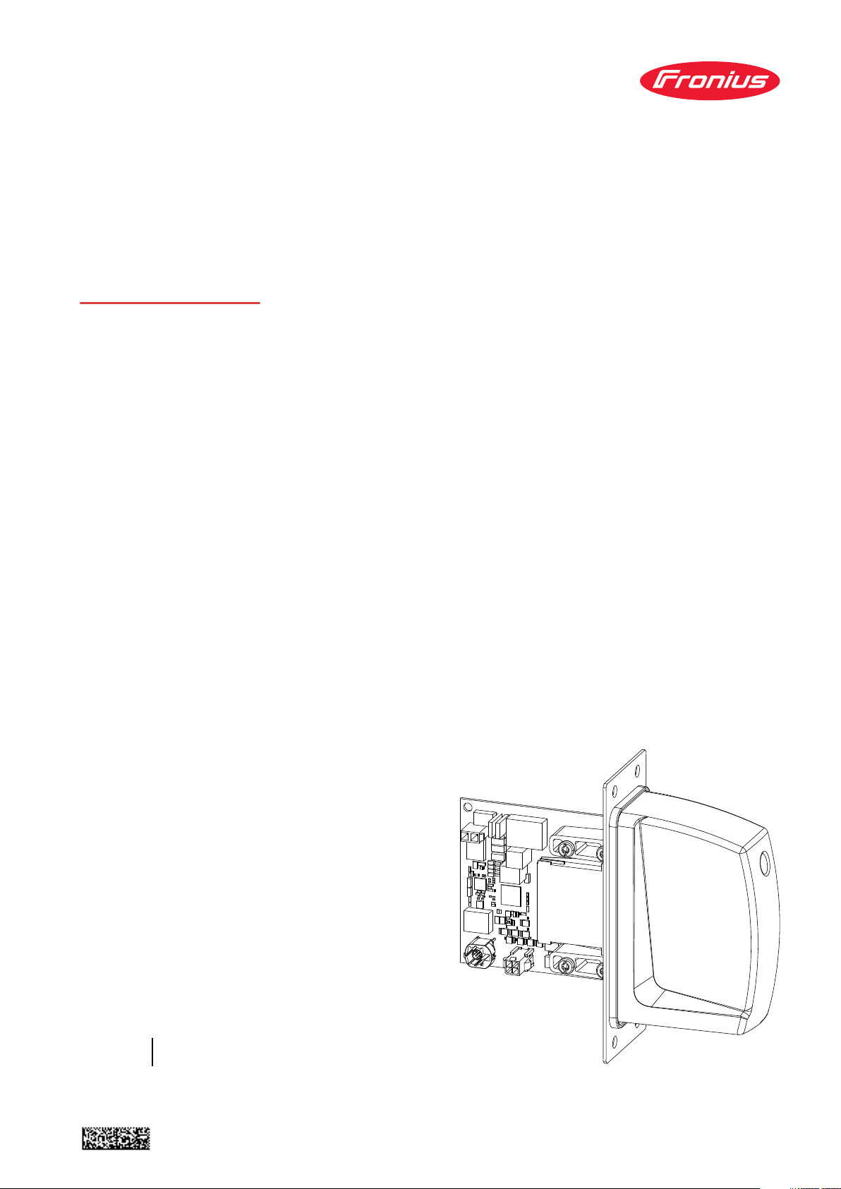
Device Concept The robot interface serves as an interface between the power source and stand-
ardized bus modules supporting a wide range of communication protocols.
Fronius may factory-fit the robot interface in the power source but it can also be
retrofitted by appropriately trained and qualified personnel.
WARNING!
All the work and functions described in this document must only be carried
out by trained and qualified personnel.
Read and understand this document.
Read and understand all the Operating Instructions for the system components, especially the safety rules.
WARNING!
Do not transfer safety signals via the interface.
4
(1) Robot control system
(2) SpeedNet data cable
(3) Robot interface
(4) Power source
(5) Cooling unit
(6) Interconnecting hosepack
(7) Wirefeeder
(8) Robot
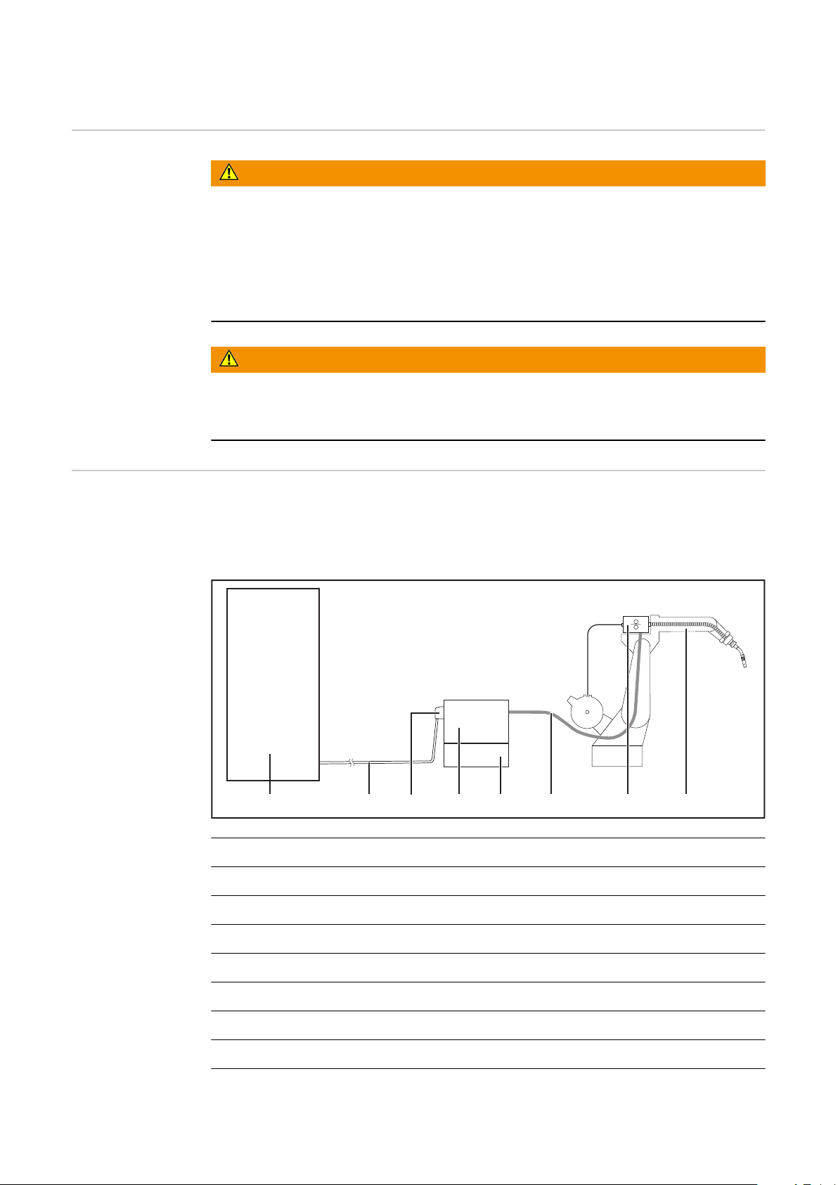
Block Diagram
Spider NT241
RI FB/i FANUC 1.0
Data
24 V
Module
(1)
(2)
(3)
EN-US
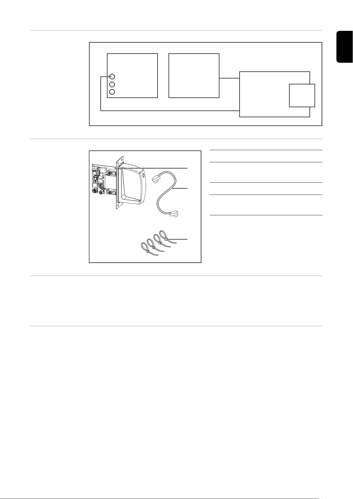
Scope of Supply
Required Tools
and Materials
Screwdriver TX8
-
Screwdriver TX20
-
Screwdriver TX25
-
Diagonal cutting pliers
-
(1) RI FB/i FANUC 1.0
(2) Data cable
4-pin
(3) Cable ties
(4) These Operating Instructions
(not pictured)
Installation Requirements
The robot interface may only be installed in the designated opening on the rear
of the power source.
5

Connections and Indicators
(2) (3)
(1)
(14)
(13)
(12)
(11)
(2)
(1)
(9)
(10)
(8)
(7)
(3) (4)
(5) (6)
Connections on
the Robot Interface
LEDs on Robot
Interface PCB
(1) Power supply connection
2-pin
(2) SpeedNet data cableconnec-
tion
4-pin
(3) Bus module connection
6
(1) ETH1 LED Green For diagnosing the network connec-
tion.
(2) ETH2 LED Orange
For details, see section below titled
"LEDs for Network Connection Diagnosis"

(3) LED 3 Green
(4) LED 4 Green
(5) LED 5 Green
(6) LED 6 Red
(7) +3V3 LED Green For diagnosing the power supply.
(8) +24V LED Green
No function
Flashes at 4 Hz = No SpeedNet
-
connection
Flashes at 20 Hz = Establishing
-
SpeedNet connection
Flashes at 1 Hz = SpeedNet con-
-
nection established
Lights up when an internal error occurs.
Remedy: Restart the robot interface.
If this does not resolve the issue, inform the service team.
For details, see section below titled
"LEDs for Power Supply Diagnosis"
EN-US
LEDs for Power
Supply Diagnosis
(9) DIG OUT 2 LED Green
(10) DIG OUT 1 LED Green
(11) LED 11 Green
(12) LED 12 Green
(13) LED 13 Green
(14) LED 14 Green
LED Indicat-orMeaning Cause
Off
+24V
Lights up
No supply voltage available
for interface
24 VDC supply voltage
present on robot interface
Digital output 2. LED lights up when
active
Digital output 1. LED lights up when
active
No function
Robot interface power
-
supply not established
Power supply cable
-
faulty
+3V3
Off
Lights up
No operating voltage
present on robot interface
3 VDC operating voltage
present on robot interface
24 VDC supply voltage
-
not present
Robot interface power
-
supply unit is faulty
7

LEDs for Network Connection
Diagnosis
LED Indicat-orMeaning Cause
No network connection
-
established for interface
Network cable faulty
-
ETH1
Off No network connection
Lights up
Flashes Data transfer in progress
Network connection established
ETH2
Off
Lights up
Transmission speed
10 Mbit/s
Transmission speed
100 Mbit/s
8

Connections and
(12)(11)(10)
(14)(13)
(9)
(1)
(2)
(3)
(4)
(5)
(6)
(7)
(8)
Indicators on RJ
45 module
(1) TX+
(2) TX-
(3) RX+
EN-US
(4),
(5)
(6) RX-
(7),
(8)
(9) Connection/activity at connection 2 LED
(10) MS LED (module status)
(11) RJ-45 Ethernet connection 2
(12) RJ-45 Ethernet connection 1
Not normally used; to ensure
signal completeness, these
pins must be interconnected
and, after passing through a
filter circuit, must terminate
at the ground conductor
(PE).
Not normally used; to ensure
signal completeness, these
pins must be interconnected
and, after passing through a
filter circuit, must terminate
at the ground conductor
(PE).
(13) Connection/activity at connection 1 LED
(14) NS LED (network status)
NS LED (Network Status)
Status Meaning
Off No supply voltage or no IP address
Lights up green Online, one or more connections established
(CIP category 1 or 3)
Flashes green Online, no connections established
Lights up red Double IP address, serious error
Flashes red Overrun of time for one or more connections
(CIP category 1 or 3)
MS LED (Module Status)
Status Meaning
Off No supply voltage
Lights up green Controlled by a Scanner in Run state and, if CIP Sync is
enabled, time is synchronized to a Grandmaster clock
Flashes green Not configured, Scanner in Idle state, or, if CIP Sync is
enabled, time is synchronized Grandmaster clock
Lights up red Major error - exception state, serious fault, etc.
9

MS LED (Module Status)
Flashes red Correctable error - the module is configured, but there
is a difference between the parameters stored and the
parameters used (configuration process image, IP address)
Connection/Activity LED
Status Meaning
Off No connection, no activity
Lights up green Connection established (100 Mbit/s)
Flickers green Activity (100 Mbit/s)
Lights up yellow Connection established (10 Mbit/s)
Flickers yellow Activity (10 Mbit/s)
10

Technical data
EN-US
Environmental
Conditions
Robot Interface
Technical Data
CAUTION!
A risk is posed by prohibited environmental conditions.
This can result in severe damage to equipment.
Only store and operate the device under the following environmental condi-
▶
tions.
Temperature range of ambient air:
During operation: -10 °C to +40 °C (14 °F to 104 °F)
-
During transport and storage: -20 °C to +55 °C (-4 °F to 131 °F)
-
Relative humidity:
Up to 50% at 40 °C (104 °F)
-
Up to 90% at 20 °C (68 °F)
-
Ambient air: free of dust, acids, corrosive gases or substances, etc.
Altitude above sea level: up to 2000 m (6500 ft).
Power supply Internal (24 V)
Degree of protection IP 23
Data Transfer
Properties
Configuration
Parameters
RJ-45 Connection
Transmission technology:
Ethernet
Medium (4 x 2 twisted-pair copper cable):
Category 3 (10 Mbit/s)
Category 5 (100 Mbit/s)
When selecting the cables, plugs, and termination resistances, the ODVA recommendation for the planning and installation of EtherNet/IP systems must
be observed.
The EMC tests were carried out by the manufacturer with the cable IEC5ES8VG0030M40M40-F.
Transmission speed:
10 Mbit/s or 100 Mbit/s
Bus connection:
RJ-45 Ethernet
In some robot control systems, it may be necessary to state the configuration
parameters described here so that the bus module can communicate with the robot.
11

Parameter Value
Vendor ID 534
Device Type C
hex
Product Code 340
hex
(12
hex
(1332
)
dec
(832
dec
dec
)
)
12

Configuration of robot interface
(1)
(2)
EN-US
General
Configuring the
Process Image
The DIP switch on the robot interface
is used to configure:
The process image (standard im-
-
age)
The IP address
-
Default setting for process image:
Positions 7 and 8 of DIP switch set to
OFF (1) = standard image = RI FB/i
FANUC 1.0
Default setting for IP address =
192.168.0.2:
Positions 6, 5, 4, 3, 1 of DIP switch
-
set to OFF (1)
Position 2 of DIP switch set to ON
-
(2)
DIP Switch
8 7 6 5 4 3 2 1 Configuration
OFF OFF
OFF ON
- - - - - -
- - - - - -
Standard-Image
(FANUC 1.0)
Not used
Setting the IP
Address
ON OFF
ON ON
- - - - - -
- - - - - -
Not used
Not used
The process image defines the volume of data transferred and the system compatibility.
You can set the IP address as follows:
Via the DIP switches within the range defined by 192.168.0.xxx
-
(xx = DIP switch setting = 0 to 63)
Setting the Address via the DIP Switches:
DIP switch
IP address
8 7 6 5 4 3 2 1
- -
- -
- -
OFF OFF OFF OFF OFF ON
OFF OFF OFF OFF ON OFF
ON ON OFF ON ON OFF
192.168.0.1
192.168.0.2
:
192.168.0.54
- -
ON ON OFF ON ON ON
192.168.0.55
13

The IP address can be set via positions 1 to 6 of the DIP switch.
The configuration is carried out in binary format. In decimal format, the setting
range is 0 through 63.
The following IP address is set via the DIP switches on delivery:
IP address: 192.168.0.2
-
Subnet mask: 255.255.255.0
-
Default gateway: 0.0.0.0
-
Configuring the
Robot Interface
Set the DIP switch in accordance with the desired configuration
1
NOTE!
Risk due to invalid DIP switch settings.
This may result in malfunctions.
Whenever changes are made to the DIP switch settings, the interface must
▶
be restarted. This is the only way for the changes to take effect.
Restart the interface = interrupting and restoring the power supply or ex-
▶
ecuting the relevant function on the website of the power source (SmartManager).
14

Installing the Robot Interface
EN-US
Safety
Preparation
WARNING!
Electrical current hazard.
This can result in serious injuries or death.
Before starting work, switch off all the devices and components involved and
▶
disconnect them from the grid.
Secure all the devices and components involved to prevent unintentional re-
▶
starting.
After opening the device, use a suitable measuring instrument to check that
▶
electrically charged components (such as capacitors) have been discharged.
WARNING!
Electrical current hazard caused by an inadequate ground conductor connection.
This can result in severe personal injury and damage to property.
Always use the original housing screws in the original quantity.
▶
1 2
3 4
15

5
Routing the Data
Cable
1 2
3
16

Installing the
Robot Interface
1 2
EN-US
Final Tasks
1 2
17

Installing the Bus Module
Safety
Installing the
Bus Module
WARNING!
Danger from electrical current.
Serious injuries or death may result.
Before starting work, switch off all devices and components involved, and
▶
disconnect them from the grid.
Secure all devices and components involved so that they cannot be switched
▶
back on.
WARNING!
Danger from electrical current due to inadequate ground conductor connection.
Serious personal injury and property damage may result.
Always use the original housing screws in the quantity initially supplied.
▶
1 2
18
3

Input and Output Signals Standard Image FANUC 1.0
Data types The following data types are used:
UINT16 (Unsigned Integer)
-
Whole number in the range from 0 to 65535
SINT16 (Signed Integer)
-
Whole number in the range from -32768 to 32767
Conversion examples:
for a positive value (SINT16)
-
e.g. desired wire speed x factor
Availability of input signals
12.3 m/min x 100 = 1230
for a negative value (SINT16)
-
e.g. arc correction x factor
-6.4 x 10 = -64
The input signals listed below are available from firmware V3.2.30 of the TPS/i
power source.
= FFC0
dec
= 04CE
dec
hex
EN-US
hex
Input signals
(from robot to
power source)
19

Address
Relative Absolute
WORD
0
BYTE
0
1
BIT
0 1 Welding Start
1 2 Robot ready High
2 3 Working mode Bit 0 High
3 4 Working mode Bit 1 High
4 5 Working mode Bit 2 High
5 6 Working mode Bit 3 High
6 7 Working mode Bit 4 High
7 8 —
0 9 Gas on
1 10 Wire forward
2 11 Wire backward
3 12 Error quit
4 13 Touch sensing
BIT
Signal
Description
Activity /
data type
Increas-
ing
Increas-
ing
Increas-
ing
Increas-
ing
Increas-
ing
Increas-
ing
Range
See table
Value range
for Working
mode on page
28
Factor
5 14 Torch blow out
6 15 Processline selection Bit 0 High See table
7 16 Processline selection Bit 1 High
Increas-
ing
Value range
Process line
selection on
page 28
20

Address
Relative Absolute
EN-US
WORD
1
BYTE
2
3
BIT
0 17 Welding Simulation High
1 18 Synchro pulse on High
2 19 SFI on High
3 20 —
4 21 —
5 22 —
6 23 Wire brake on High
7 24 Torchbody Xchange High
0 25 —
1 26 Teach mode High
2 27 —
3 28 —
4 29 —
5 30 Wire sense start
6 31 Wire sense break
BIT
Signal
Description
Activity /
data type
Increas-
ing
Increas-
ing
Range
Factor
7 32 —
21

Address
Relative Absolute
WORD
2
BYTE
4
BIT
0 33 TWIN mode Bit 0 High See table
1 34 TWIN mode Bit 1 High
2 35 —
3 36 —
4 37 —
5 38 Documentation mode High
6 39 —
7 40 —
0 41 —
1 42 —
2 43 —
BIT
Signal
Description
Activity /
data type
Value Range
for TWIN
Mode on page
See table
Value Range
for Document-
ation mode on
page 29
Range
29
Factor
3 44 —
5
4 45 —
5 46 —
6 47 —
7 48
Disable process controlled correction
High
22

Address
Relative Absolute
EN-US
WORD
3
BYTE
6
7
BIT
0 49 —
1 50 —
2 51 —
3 52 —
4 53 —
5 54 —
6 55 —
7 56 —
0 57 ExtInput1 => OPT_Output 1 High
1 58 ExtInput2 => OPT_Output 2 High
2 59 ExtInput3 => OPT_Output 3 High
3 60 ExtInput4 => OPT_Output 4 High
4 61 ExtInput5 => OPT_Output 5 High
5 62 ExtInput6 => OPT_Output 6 High
6 63 ExtInput7 => OPT_Output 7 High
7 64 ExtInput8 => OPT_Output 8 High
BIT
Signal
Description
Activity /
data type
Range
Factor
4
5
8 0–7
9 0–7
10,
0–7 81–96
11
65–80
Welding characteristic- / Job
number
For the welding processes
MIG/MAG pulse synergic,
MIG/MAG standard synergic,
MIG/MAG standard manual,
MIG/MAG PMC,
MIG/MAG LSC,
CMT,
ConstantWire:
Wire feed speed command
value
For job operation:
Power correction
Group
3
Group
3
UINT16
SINT16
SINT16
0 to
1000
-327.68
to 327.67
[m/min]
-20.00 to
20.00
[%]
1
10
0
23

Address
Relative Absolute
WORD
6
7
BYTE
12,
0–7 97–112
13
14,
0–7 113–128
15
BIT
BIT
Signal
Welding processes
MIG/MAG pulse synergic,
MIG/MAG standard synergic,
MIG/MAG PMC,
MIG/MAG LSC,
CMT:
Arclength correction
For the welding process
MIG/MAG standard manual:
Welding voltage
For job operation:
Arclength correction
In the welding process ConstantWire:
Hotwire current
For the welding processes
MIG/MAG pulse synergic,
MIG/MAG standard synergic,
MIG/MAG PMC,
MIG/MAG LSC,
CMT:
Pulse-/dynamic correction
Description
Group
3
Group
3
Activity /
data type
SINT16
UINT16
SINT16
UINT16
SINT16
Range
-10.0 to
100.0
[m/min]
0.0 to
6553.5
[V]
-10.0 to
10.0
[steps]
0.0 to
6553.5
[A]
-10.0 to
10.0
[steps]
Factor
10
10
10
10
10
8
9
10
11
12
13
16 0–7
17 0–7
18 0–7
19 0–7
20 0–7
21 0–7
22 0–7
23 0–7
24 0–7
25 0–7
26 0–7
27 0–7
For the welding process
MIG/MAG standard manual:
Dynamic
129–144 Wire retract correction
145–160 Welding speed
161–176 Process controlled correction
177–192 —
193–208 —
209–224 —
Group
2
Group
3
Group
2
UINT16
UINT16 0 to 10 10
UINT16
See table Value range
Process controlled cor-
rection on page 29
0.0 to
10.0
[steps]
0 to
1000
[cm/min]
10
10
24

Address
Relative Absolute
EN-US
WORD
14
15
16
17
18
19
BYTE
28 0–7
29 0–7
30 0–7
31 0–7
32 0–7
33 0–7
34 0–7
35 0–7
36 0–7
37 0–7
38 0–7
39 0–7
0 321
1 322 Disable SFI-Parameter (Image) High
BIT
BIT
225–240 —
241–256 Wire forward / backward length UINT16
257–272 Wire sense edge detection
273–288 —
289–304 —
305–320 Seam number
Signal
Disable Start-End-Parameter
(Image)
Description
Group
2
Activity /
data type
OFF / 1
to 65535
[mm]
OFF /
UINT16
UINT
16
High
0.5 to 20
[mm]
0 to
65,535
Range
Factor
1
10
1
20
40
41
2 323 Disable SP-Parameter (Image) High
3 324
4 325 Disable gas-settings (Image) High
5 326
6 327
7 328
0 329
1 330 —
2 331 —
3 332 —
4 333 —
5 334 —
6 335 —
Disable Process-Mix-Parameter
(Image)
Disable components setup
(TAG)
Disable language/units/standards (TAG)
Disable process controlled correction 2 (Image)
Enable arc break monitoring /
arc loss
High
High
High
High
High
7 336 —
25

Address
Relative Absolute
21
WORD
42
43
BYTE
BIT
0 337 Enable resistance overwrite High
1 338 Set resistance value High
2 339 Enable inductance overwrite High
3 340 Set inductance value High
4 341 —
5 342 —
6 343 —
7 344 —
0 345 —
1 346 —
2 347 —
3 348 —
4 349 —
5 350 —
6 351 Command value selection Bit 0 High See table
7 352
BIT
Signal
Reserve (Command value selection Bit 1)
Description
Activity /
data type
Value Range
for Command
value selection
Range
on page 29
Factor
44 0–7
22
45 0–7
46 0–7
23
47 0–7
48 0–7
24
49 0–7
50 0–7
25
51 0–7
52 0–7
26
53 0–7
54 0–7
27
55 0–7
56 0–7 449–456 TAG Quantity UINT 8 0 to 8 1
28
57 0–7 457–464 TAG Command
353–368 TAG Start address
369–384 TAG value 1
385–400 TAG value 2
401–416 TAG value 3
417–432 TAG value 4
433–448 TAG value 5
Group
1
Group
1
Group
1
Group
1
Group
1
0x0001
= TAG
Read |
0x0002
=TAG
Write
UINT
16
UINT
16
UINT
16
UINT
16
UINT
16
UINT
16
UINT 8 0 to 2 1
0 to
65,535
1
1
1
1
1
1
26

Address
Relative Absolute
EN-US
WORD
29
30
31
32
33
34
35
36
BYTE
58 0–7
59 0–7
60 0–7
61 0–7
62 0–7
63 0–7
64 0–7
65 0–7
66 0–7
67 0–7
68 0–7
69 0–7
70 0–7
71 0–7
72 0–7
73 0–7
BIT
BIT
465–480 Gas preflow
481–496 Gas postflow
497–512 Inching Value
513–528 S2T Starting current
529–544 S2T Starting current time
545–560 S2T Slope 1
561–576 S2T Slope 2
577–592 S2T End current
Signal
Description
Group
2
Group
2
Group
2
Group
2
Group
2
Group
2
Group
2
Group
2
Activity /
data type
UINT
16
UINT
16
SINT 16
UINT
16
UINT
16
UINT
16
UINT
16
UINT
16
Range
0 to 9.9
[s]
0 to 60
[s]
0.5 to 25
[m/min]
0 to 200
[%]
Off (0) /
0.1 to 10
[s]
0 to 9.9
[s]
0 to 9.9
[s]
0 to 200
[%]
Factor
10
10
10
0
1
10
10
10
1
37
38
39
40
41
42
43
44
74 0–7
75 0–7
76 0–7
77 0–7
78 0–7
79 0–7
80 0–7
81 0–7
82 0–7
83 0–7
84 0–7
85 0–7
86 0–7
87 0–7
88 0–7
89 0–7
593–608 S2T End current time
609–624 S2T Start Arclength correction
625–640 S2T End Arclength correction
641–656
657–672
673–688
689–704 SFI Hotstart
705–720 Process controlled correction 2
Process-Mix High power time
correction
Process-Mix Low power time
correction
Process-Mix Low power correction
Group
2
Group
2
Group
2
Group
3
Group
3
Group
3
Group
2
Group
2
UINT
16
SINT 16
SINT 16
SINT 16
SINT 16
SINT 16
UINT
16
See table Value range
Process controlled cor-
rection 2 on page 29
Off (0) /
0.1 to 10
[s]
-10 to
+10
-10 to
+10
-10 to
+10
-10 to
+10
-10 to
+10
Off
(0.0) /
0.01 to
2.00
[s]
10
10
10
10
10
10
10
0
27

Address
Relative Absolute
WORD
45
46
47
48
49
50
51
BYTE
90 0–7
91 0–7
92 0–7
93 0–7
94 0–7
95 0–7
96 0–7
97 0–7
98 0–7
99 0–7
100 0–7
101 0–7
102 0–7
103 0–7
BIT
BIT
Signal
721–736 SP Delta wire feed
737–752 SP Frequency
753–768 SP Duty Cycle
769–784 SP Arclength correction high
785–800 SP Arclength correction low
801–816 Resistance
817–832 Inductance
Description
Group
2
Group
2
Group
2
Group
2
Group
2
Group
2
Group
2
Activity /
data type
SINT 16
SINT 16
SINT 16
SINT 16
SINT 16
UINT
16
UINT
16
Range
-10 to
+10
-10 to
+10
-100 to
+100
-10 to
+10
-10 to
+10
0 to
+400
[mOhm]
0 to
+250
[micro-
henries]
Factor
10
10
1
10
10
10
10
Value range for
Working mode
Value range Process line selection
Bit 4 Bit 3 Bit 2 Bit 1 Bit 0 Description
0 0 0 0 0 Internal parameter selection
0 0 0 0 1 Special 2-step mode characteristics
0 0 0 1 0 Job mode
0 1 0 0 0 2-step mode characteristics
0 1 0 0 1 MIG/MAG Standard Manual, 2-step
1 1 0 0 0 R/L measurement
1 1 0 0 1 R/L alignment
Value range for operating mode
Bit 1 Bit 0 Description
0 0 Process line 1 (default)
0 1 Process line 2
1 0 Process line 3
1 1 Reserved
Value range for process line selection
28

Value Range for
TWIN Mode
Bit 1 Bit 0 Description
0 0 TWIN Single mode
0 1 TWIN Lead mode
1 0 TWIN Trail mode
1 1 Reserved
Value range for TWIN mode
EN-US
Value Range for
Documentation
mode
Value range Process controlled
correction
Value Range for
Command value
selection
Bit 0 Description
0 Seam number of power source (internal)
1 Seam number of robot
Value range for documentation mode
Activity
Data
Process Signal
type
Arc length stabil-
PMC
Value range for process-dependent correction
Bit
Description
izer SINT16
351
0 Wirefeeder set value
Value range
Configuration
range Unit
-3276.8 to
+3276.7
0.0 to +5.0 Volts 10
Facto
r
Value range Process controlled
correction 2
1 Welding current set value
Value range for set value
Activity
Process Signal
PMC,
LSC
Value range for process-dependent correction 2
Penetration stabil-
izer SINT16
Data
type
Value range
Configuration
Facto
range Unit
-3276.8 to
+3276.7
0.0 to +10.0 m/min 10
r
29

Availability of
the output signals
Output signals
(from power
source to robot)
Address
Relative Absolute
The output signals listed below are available from firmware V3.2.30 of the TPS/i
power source.
WORD
0
BYTE
0
1
BIT
0 1 Heartbeat Powersource 1 Hz
1 2 Power source ready High
2 3 Warning High
3 4 Process active High
4 5 Current flow High
5 6 Arc stable- / touch signal High
6 7 Main current signal High
7 8 Touch signal High
0 9 Collisionbox active Low
1 10 Robot Motion Release High
2 11 Wire stick workpiece High
3 12 —
4 13 Short circuit contact tip High
5 14 Parameter selection internally High
BIT
Signal
Description
Activity /
data type
Range
0 = colli-
sion or
cable
break
Factor
30
6 15 Characteristic number valid High
7 16 Torch body gripped High

Address
Relative Absolute
EN-US
WORD
1
BYTE
2
3
BIT
0 17 Command value out of range High
1 18 Correction out of range High
2 19 —
3 20 Limitsignal High
4 21 —
5 22 —
6 23 Main supply status Low
7 24 —
0 25 Sensor status 1 High
1 26 Sensor status 2 High
2 27 Sensor status 3 High
3 28 Sensor status 4 High
4 29 —
5 30 —
6 31 —
7 32 —
BIT
Signal
Description
Activity /
data type
See table As-
signment of
Statuses 1–4
Range
Sensor
on page 36
Factor
0 33 Function status Bit 0 High See table
Value Range
1 34 Function status Bit 1 High
2 35 —
4
2
5
3 36 Safety status Bit 0 High See table
4 37 Safety status Bit 1 High
5 38 —
6 39 Notification High
7 40 System not ready High
0 41 —
1 42 —
2 43 —
3 44 —
4 45 —
5 46 —
for Function
status on page
36
Value range
Safety status
on page 36
6 47 —
7 48 —
31

Address
Relative Absolute
WORD
3
BYTE
6
7
BIT
0 49 Process Bit 0 High
1 50 Process Bit 1 High
2 51 Process Bit 2 High
3 52 Process Bit 3 High
4 53 Process Bit 4 High
5 54 —
6 55 Gas nozzle touched High
7 56 TWIN synchronisation active High
0 57 ExtOutput1 <= OPT_Input1 High
1 58 ExtOutput2 <= OPT_Input2 High
2 59 ExtOutput3 <= OPT_Input3 High
3 60 ExtOutput4 <= OPT_Input4 High
4 61 ExtOutput5 <= OPT_Input5 High
5 62 ExtOutput6 <= OPT_Input6 High
6 63 ExtOutput7 <= OPT_Input7 High
7 64 ExtOutput8 <= OPT_Input8 High
BIT
Signal
Description
Activity /
data type
See table
Value Range
for Process Bit
on page 37
Range
Factor
4
5
6
7
8
9
10
8 0–7
9 0–7
10 0–7
11 0–7
12 0–7
13 0–7
14 0–7
15 0–7
16 0–7
17 0–7
18 0–7
19 0–7
20 0–7
21 0–7
Group
65–80 Real value welding voltage
81–96 Real value welding current
97–112 Real value wire feed speed
113–128
129–144 Error number UINT16
145–160 Warning number UINT16
161–176 Motor current M1 SINT16
Actual real value for seam
tracking
3 ana-
log
meter
Group
3 ana-
log
meter
Analog
meter
UINT16
UINT16
UINT16
SINT16
0.0 to
327.67
[V]
0.0 to
327.67
[A]
-327.68
to 327.67
[m/min]
0 to
65,535
0 to
65,535
0 to
65,535
-327.68
to 327.67
[A]
10
0
10
10
0
10
00
0
1
1
10
0
32
11
22 0–7
23 0–7
177–192 Motor current M2 SINT16
-327.68
to 327.67
[A]
10
0

Address
Relative Absolute
EN-US
WORD
12
13
14
15
16
17
18
19
BYTE
24 0–7
25 0–7
26 0–7
27 0–7
28 0–7
29 0–7
30 0–7
31 0–7
32 0–7
33 0–7
34 0–7
35 0–7
36 0–7
37 0–7
38 0–7
39 0–7
BIT
BIT
193–208 Motor current M3 SINT16
209–224 —
225–240 —
241–256 —
257–272 Wire position SINT16
273–288 —
289–304 —
305–320 —
Signal
Description
Activity /
data type
-327.68
to 327.67
[A]
-327.68
to 327.67
[mm]
Range
Factor
10
0
10
0
20
0 321 WebJobEditor enable High
1 322 —
2 323 —
3 324 —
40
4 325 —
5 326 —
6 327 —
7 328 —
0 329 —
1 330 —
2 331 —
3 332 —
41
4 333 —
5 334 —
6 335 —
7 336 —
33

Address
Relative Absolute
21
WORD
42
43
BYTE
BIT
0 337 — High
1 338 —
2 339 —
3 340 —
4 341 —
5 342 —
6 343 —
7 344 —
0 345 —
1 346 —
2 347 —
3 348 —
4 349 —
5 350 —
6 351 —
7 352 —
BIT
Signal
Description
Activity /
data type
Range
Factor
44 0–7
22
45 0–7
46 0–7
23
47 0–7
48 0–7
24
49 0–7
50 0–7
25
51 0–7
52 0–7
26
53 0–7
54 0–7
27
55 0–7
56 0–7 449–456 TAG Quantity UINT8 0 to 5 1
28
57 0–7 457–464 TAG Command
353–368 TAG Start adress UINT16
369–384 TAG value 1 UINT16
385–400 TAG value 2 UINT16 1
401–416 TAG value 3 UINT16 1
417–432 TAG value 4 UINT16 1
433–448 TAG value 5 UINT16 1
0x0001
= TAG
Read |
0x0002
=TAG
Write
UINT8 0 to 2 1
0 to
65,535
1
34
29
58 0–7
59 0–7
465–480 Cooler temperature SINT16
-100 to
+200
[°C]
10

Address
Relative Absolute
EN-US
WORD
30
31
32
33
34
35
36
37
BYTE
60 0–7
61 0–7
62 0–7
63 0–7
64 0–7
65 0–7
66 0–7
67 0–7
68 0–7
69 0–7
70 0–7
71 0–7
72 0–7
73 0–7
74 0–7
75 0–7
BIT
BIT
481–496 Cooler flow rate SINT16
497–512 Real energy actual value UINT16
513–528 Power value UINT16
529–560 Hour meter power on UINT32
561–576
577–592
593–608 Gaspreflow UINT16
Signal
Arc on time UINT32
Description
Activity /
data type
Range
-100 to
+100 [l/
min]
0 to
6553.5
[kJ]
0 to
6553.5
[kW]
0 to
100000
[h]
0 to
100000
[h]
0.0 to
9.9 [s]
Factor
10
0
10
10
10
10
10
38
39
40
41
42
43
44
45
76 0–7
77 0–7
78 0–7
79 0–7
80 0–7
81 0–7
82 0–7
83 0–7
84 0–7
85 0–7
86 0–7
87 0–7
88 0–7
89 0–7
90 0–7
91 0–7
609–624 Gaspostflow UINT16
625–640 S2T Starting current time UINT16
641–656 S2T Slope 1 UINT16
657–672 S2T Slope 2 UINT16
673–688 S2T End current time UINT16
689–704 —
705–720 —
721–736 —
0.0 to
60.0 [s]
Off (0) /
0.1 to
10.0 [s]
0.0 to
9.9 [s]
0.0 to
9.9 [s]
Off (0) /
0.1 to 10
[s]
10
10
10
10
10
46
92 0–7
737–752 —
93 0–7
35

Address
Relative Absolute
WORD
BYTE
94 0–7
47
95 0–7
96 0–7
48
97 0–7
98 0–7
49
99 0–7
100 0–7
50
101 0–7
102 0–7
51
103 0–7
Assignment of
Sensor Statuses
1–4
BIT
BIT
Signal
Description
Activity /
data type
753–768 —
769–784 —
785–800 —
0 to
+400
[mOhm]
801–816 Resistance
Group
2
UINT16
0 to
817–832 Inductance
Group
2
UINT16
+250
[micro-
henries]
Signal Description
Sensor status 1 OPT/i WF R wire end (4,100,869)
Sensor status 2 OPT/i WF R wire drum (4,100,879)
Range
Factor
10
10
Value range
Safety status
Value Range for
Function status
Sensor status 3 OPT/i WF R ring sensor (4,100,878)
Sensor status 4 Wire buffer set CMT TPS/i (4,001,763)
Bit 1 Bit 0 Description
0 0 Reserve
0 1 Hold
1 0 Stop
1 1 Not installed / active
Bit 1 Bit 0 Description
0 0 inactive
0 1 idle
1 0 finished
36
1 1 Error
Value range for function status

Value Range for
Process Bit
Bit 4 Bit 3 Bit 2 Bit 1 Bit 0 Description
0 0 0 0 0 No internal parameter selection or
process
0 0 0 0 1 MIG/MAG pulse synergic
0 0 0 1 0 MIG/MAG standard synergic
0 0 0 1 1 MIG/MAG PMC
0 0 1 0 0 MIG/MAG LSC
0 0 1 0 1 MIG/MAG standard manual
0 0 1 1 0 Electrode
0 0 1 1 1 TIG
0 1 0 0 0 CMT
0 1 0 0 1 ConstantWire
EN-US
TAG Table for
Input Signals
Address TAG Value
BIT 325 Disable Gas settings:
TAG 30 MIG Gasvalue
TAG 31 MIG Gasfactor
TAG 32 —
TAG 33 —
TAG 34 —
TAG 35 —
TAG 36 —
TAG 37 —
TAG 38 —
TAG 39 —
Address TAG Value
BIT 326 Disable components setup:
TAG 40 Cooling unit mode See table Value Range for
Cooling unit mode on page
38
TAG 41 Delay time flow sensor
TAG 42 Touch sensing sensitivity
TAG 43 Ignition time out
TAG 44 —
TAG 45 —
TAG 46 —
TAG 47 —
TAG 48 —
37

Address TAG Value
BIT 326 Disable components setup:
TAG 49 —
Address TAG Value
BIT 327 Disable language/units/
standards:
TAG 50 Language See Value Table on page 38
TAG 51 Unit (metric/imperial)
TAG 52 Welding standard (AWS/EU)
TAG 53 —
TAG 54 —
TAG 55 —
TAG 56 —
TAG 57 —
TAG 58 —
TAG 59 —
TAG 60 Arc break filter time / arc
loss error time
TAG 61 Arc break monitoring reac-
tion
Value Range for
Cooling unit
mode
Value Table
TAG 40 Description
1 eco
2 auto
3 on
4 off
Value Range for Cooling unit mode
Address Description Value
Language:
0 —
1 English
2 German
3 Japanese
4 Chinese
5 Spanish
38
6 French
7 Czech

Address Description Value
Language:
8 Hungarian
9 Italian
10 Norwegian
11 Polish
12 Portuguese
13 Slovakian
14 Turkish
15 Russian
16 Swedish
17 Estonian
18 Finnish
19 Lithuanian
20 Latvian
21 Dutch
22 Slovenian
EN-US
23 Romanian
24 Croatian
25 Ukrainian
26 Korean
27 Icelandic
28 Vietnamese
29 Thai
30 Indonesian
31 Serbian
32 Hindi
33 Tamil
34 Danish
35 Bulgarian
Address Description Value
Unit (imperial/metric):
0 —
1 Imperial
2 Metric
Address Description Value
Welding standard (AWS/EU):
0 —
1 AWS
39

Address Description Value
Welding standard (AWS/EU):
2 CEN
TAG Table for
Output Signals
Address Description Value
Welding-relevant values:
TAG 10001 Welding voltage
TAG 10002 Welding current
TAG 10003 Wire feed speed
TAG 10004 Real value power
TAG 10005 Ignitiondistance
TAG 10006 —
TAG 10007 —
TAG 10008 —
TAG 10009 —
TAG 10010 —
TAG 10011 —
TAG 10012 —
TAG 10013 —
TAG 10014 —
TAG 10015 —
Address Description Value
Welding system-relevant values:
TAG 10100 Vd max. processline
TAG 10101 Max. current weldingsystem
TAG 10102 —
TAG 10103 Safety status
TAG 10104 —
TAG 10105 —
TAG 10106 —
TAG 10107 —
TAG 10108 —
TAG 10109 —
TAG 10110 —
TAG 10111 —
40

Address Description Value
Documentation-relevant values:
TAG 10200 Welding time
TAG 10201 Section time
TAG 10202 —
EN-US
41

42

EN-US
43

Fronius International GmbH
Froniusstraße 1
4643 Pettenbach
Austria
contact@fronius.com
www.fronius.com
Under www.fronius.com/contact you will find the adresses
of all Fronius Sales & Service Partners and locations.
spareparts.fronius.com
SPAREPARTS
ONLINE
 Loading...