

Wels, February 13th, 2015
RIDE-THROUGH CAPABILITIES
FRONIUS PRIMO 3.8-1 – 8.2-1
Fronius International GmbH
hereby confirms, that the inverters
/ Fronius Primo 3.8-1 208/240, 5.0-1 208/240, 6.0-1 208/240, 7.6-1 208/240, and 8.2-1 208/240
Are capable of meeting the following ride-through and trip settings:
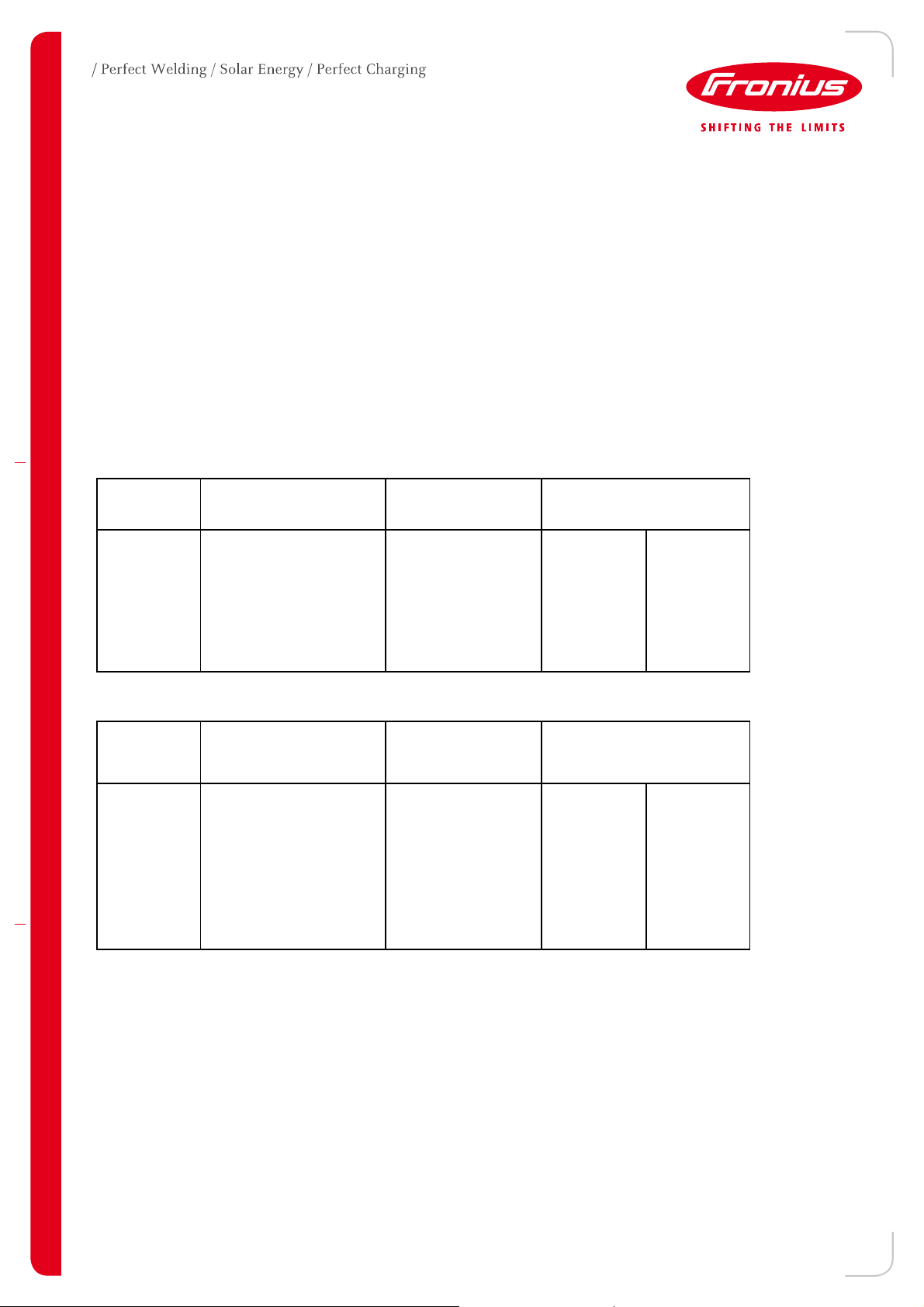
Operating
Region
OFR2 f > 64 Cease to Energize 0.1667
OFR1 64 > f = > 63 Ride Through 20 21
NORH 63 = > f > 60 Normal Operation Indefinite Indefinite
NORL
UFR1 57 > f = > 56 Ride Through 20 21
UFR2 f < 56 Cease to Energize 0.01667
Range ( Hz) Operating Mode
60 = > f = > 57
Normal Operation Indefinite Indefinite
Ride Through Trip
Duration (s)
Operating
Region
OVR2 V > 120 Cease to Energize 0.1667
OVR1 120 >= V > 110 Cease to Energize .92 1
NORH 110 >= V > 100 Normal Operation Indefinite Indefinite
NORL 100 >= V >= 88 Normal Operation Indefinite Indefinite
UVR1 88 > V >= 70 Ride Through 20 21
UVR2 70 > V >= 50 Ride Through
UVR3 V < 50 Permissive Operation 0.5
Range ( %) Operating Mode
Ride Through Trip
Duration (s)
20 21
Additionally, the inverters can meet Return to Service requirements of 60.1 ≥ f ≥ 59.9, 110 ≥ V ≥ 88 and 300 –
600s. The inverters can meet frequency ride-through requirements in the range of 50 – 65 Hz.
At a voltage drop down to 50% of the nominal voltage the inverter is capable of staying connected for at least
21 sec.
At a frequency drop down to 55 Hz the inverter is capable of staying connected for at least 21 sec. At a
frequency rise of 65 Hz the inverter is capable of staying connected for at least 21 sec.
The trip limits of the inverter have to be set in a way not contradicting this behavior.
To demonstrate this behavior test results are shown in this certificate.
02/2011
1/19
Test Data
Fronius has collected test data on a representative sample of the Primo 8.2-1 208/240 to verify ride-through
behavior based on voltage and frequency variation tests described as follows. Other Primo power classes were
not tested as the hardware is the same as the model
tested (only peak power output differs).
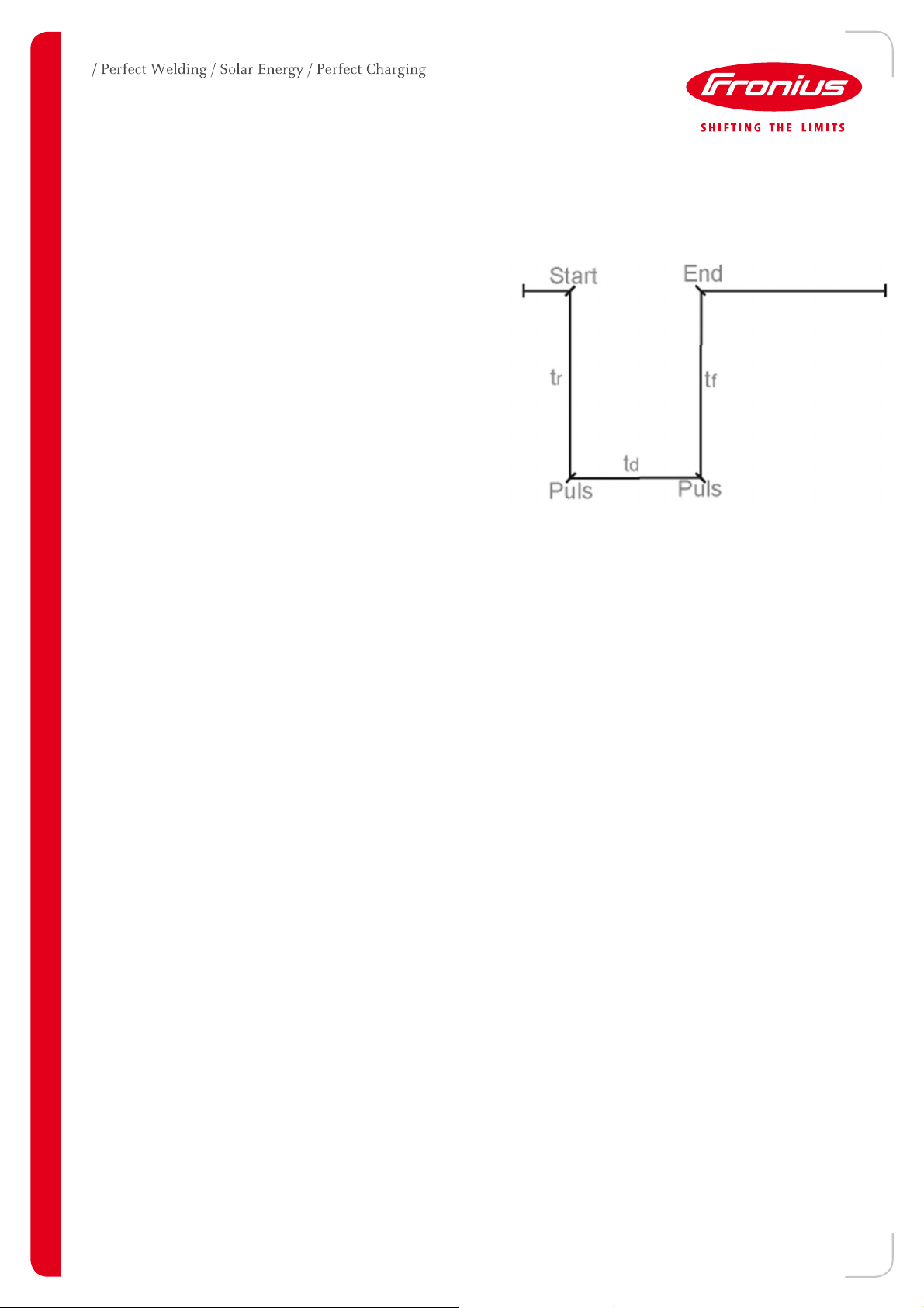
Each test uses an AC grid simulator to achieve a step or
ramp function depicted at right.
02/2011
2/19
Voltage Ride-Through Test
Model: Fronius Primo 8.2-1 208/240 (Setup 240N)
Test Conditions: 240VAC (phase to phase), 60Hz, 8200W output
Step:
Start: 240V (Phase to Phase) tr: 0s
Pulse: 120V (Phase to Phase) td: 21s
End: 240V (Phase to Phase) tf: 0s
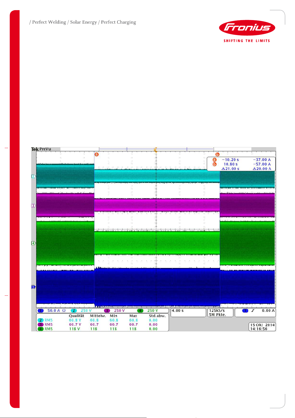
Oscillograms:
TEST 1
Chanel 1: Current on Phase 1
Chanel 2: Voltage Phase 1 to N
Chanel 3: Voltage Phase 2 to N
Chanel 4: Voltage Phase 1 to Phase 2
02/2011
3/19
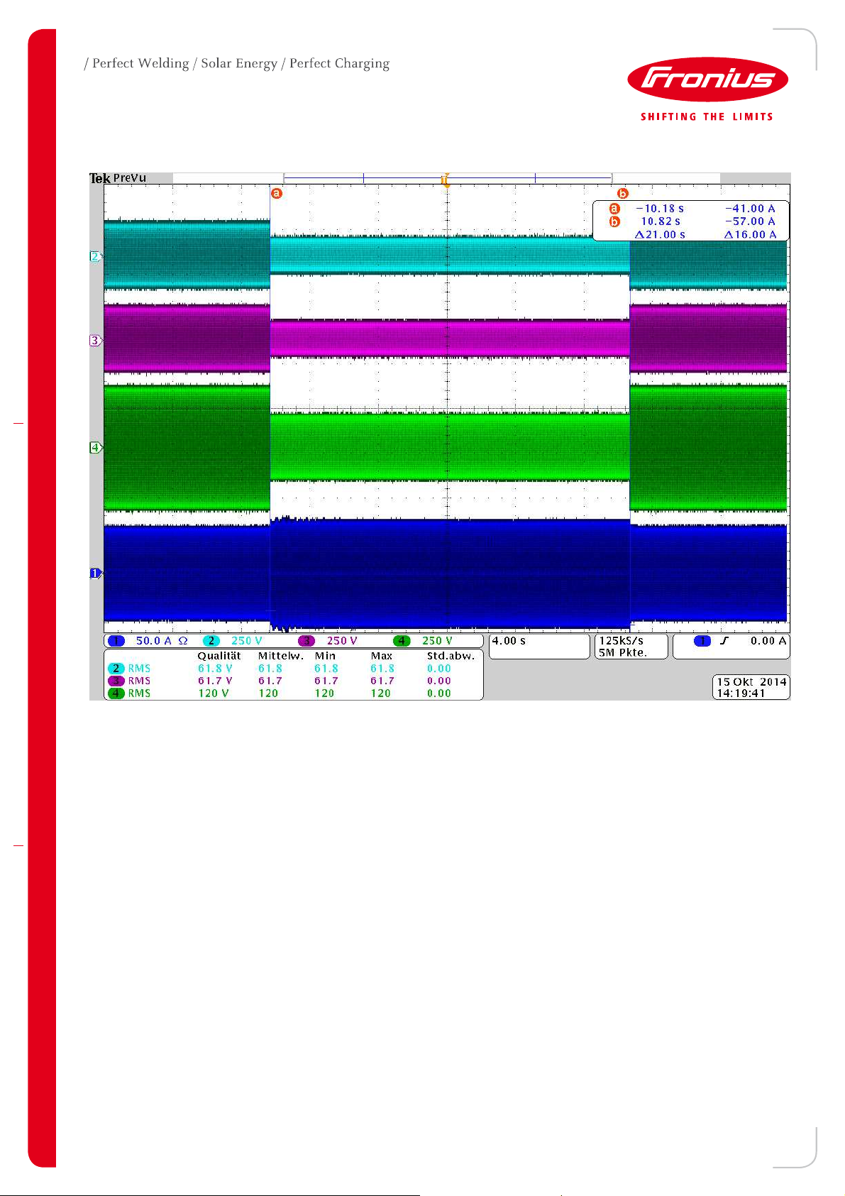
TEST 2
Chanel 1: Current on Phase 1
Chanel 2: Voltage Phase 1 to N
Chanel 3: Voltage Phase 2 to N
Chanel 4: Voltage Phase 1 to Phase 2
02/2011
4/19

TEST 3
Chanel 1: Current on Phase 1
Chanel 2: Voltage Phase 1 to N
Chanel 3: Voltage Phase 2 to N
Chanel 4: Voltage Phase 1 to Phase 2
02/2011
5/19

TEST 4
Chanel 1: Current on Phase 1
Chanel 2: Voltage Phase 1 to N
Chanel 3: Voltage Phase 2 to N
Chanel 4: Voltage Phase 1 to Phase 2
02/2011
6/19
 Loading...