

Page 1

/ Battery Charging Systems / Welding Technology / Solar Electronics
RCU 2000
Bedienungsanleitung
DEENFR
Fernbedienung
Operating Instructions
Remote control
Mode d’emploi
Télécommande
42,0410,0941 002-06042012
RCU 2000
Page 2

Page 3

Sehr geehrter Leser
DE
Einleitung
Wir danken Ihnen für Ihr entgegengebrachtes Vertrauen und gratulieren Ihnen zu Ihrem
technisch hochwertigen Fronius Produkt. Die vorliegende Anleitung hilft Ihnen, sich mit
diesem vertraut zu machen. Indem Sie die Anleitung sorgfältig lesen, lernen Sie die
vielfältigen Möglichkeiten Ihres Fronius-Produktes kennen. Nur so können Sie seine
Vorteile bestmöglich nutzen.
Bitte beachten Sie auch die Sicherheitsvorschriften und sorgen Sie so für mehr Sicherheit am Einsatzort des Produktes. Sorgfältiger Umgang mit Ihrem Produkt unterstützt
dessen langlebige Qualität und Zuverlässigkeit. Das sind wesentliche Voraussetzungen
für hervorragende Ergebnisse.
ud_fr_st_et_00491 01/2012
Page 4

Page 5
Allgemeines
DE
Produktkonzept
Systemvoraussetzungen
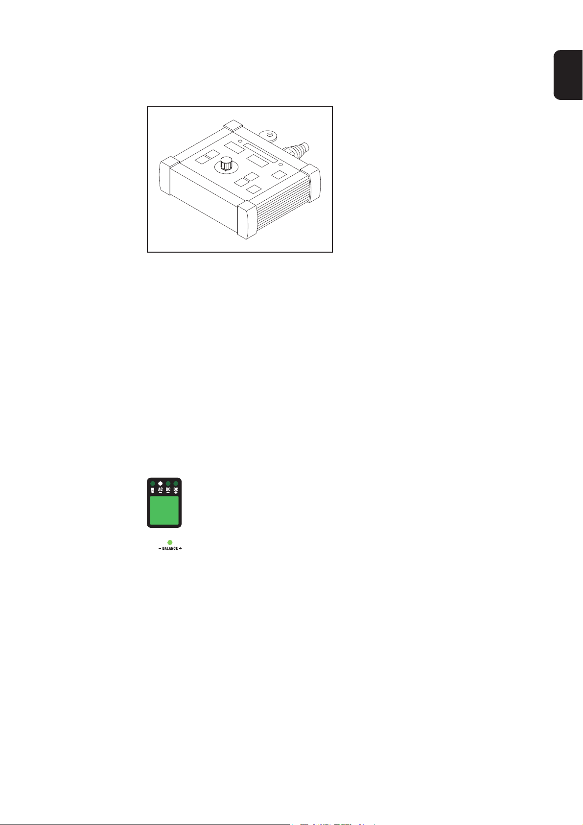
Die Fernbedienung RCU 2000 ermöglicht
den Fernbetrieb einer Stromquelle. Der
Fernbetrieb kann beispielsweise für
R
C
U
2
0
0
0
Einrichtzwecke von Stromquellen in
Fertigungszellen dienen. Die Funktionen
an der Fernbedienung entsprechen dem
Bedienpanel der Stromquelle MagicWave
1700/2200.
Abb1. Fernbedienung RCU 2000
Der Betrieb der Fernbedienung RCU 2000 ist in Verbindung mit folgenden Stromquellen
möglich:
- MagicWave 1700/2200
- MagicWave 2500/3000
- MagicWave 4000/5000
- TransTig 2200
- TransTig 2500/3000
- TransTig 4000/5000
- TransPocket 4000/5000
- TransSynergic 4000/5000
- TransPuls Synergic 2700/3200/4000/5000
Wichtig! Wird die Stromquelle TransTig 2200 von der Fernbedienung RCU 2000 aus
bedient, sind folgende Bedien- / Anzeigeelemente außer Funktion:
- Taste Verfahren
- Parameter Balance
Wichtig! Sämtliche Bedien- und Anzeigeelemente für das HF-Zünden (HochfrequenzZünden) sind außer Funktion wenn über die Fernbedienung RCU 2000 folgende Stromquellen bedient werden:
- TransPocket 4000/5000
- TransSynergic 4000/5000
- TransPuls Synergic 2700/3200/4000/5000
1
Page 6

Fernbedienung
anschließen
Stecker des Fernbedienungskabels an der Anschlußbuchse LocalNet (A) anstecken
(A)
(A)
Schlüsselschalter
Abb.2 Vorderansicht MW/TT 1700/2200
(A)
Abb.4 Rückansicht TS/TPS 3200/4000/5000
Abb.3 Vorderansicht TPS 2700
(A)
Abb.5 Vorderansicht TP 4000/5000
HINWEIS! Bei Schlüsselschalter
in waagerechter Position (B) sind
alle Tasten am Bedienpanel
gesperrt:
- Am Bedienpanel leuchtet das Schlüssel-Symbol (C)
- Wird dennoch eine Taste gedrückt,
erscheint an den Anzeigen kurz die
Sperrmeldung „Clo|SEd“. Nur jener
Parameter, der zum Zeitpunkt der
Tastensperre angewählt war, kann
mittels Einstellrad geändert werden.
(B)(C)
Abb.6 Schlüsselschalter
2
Page 7
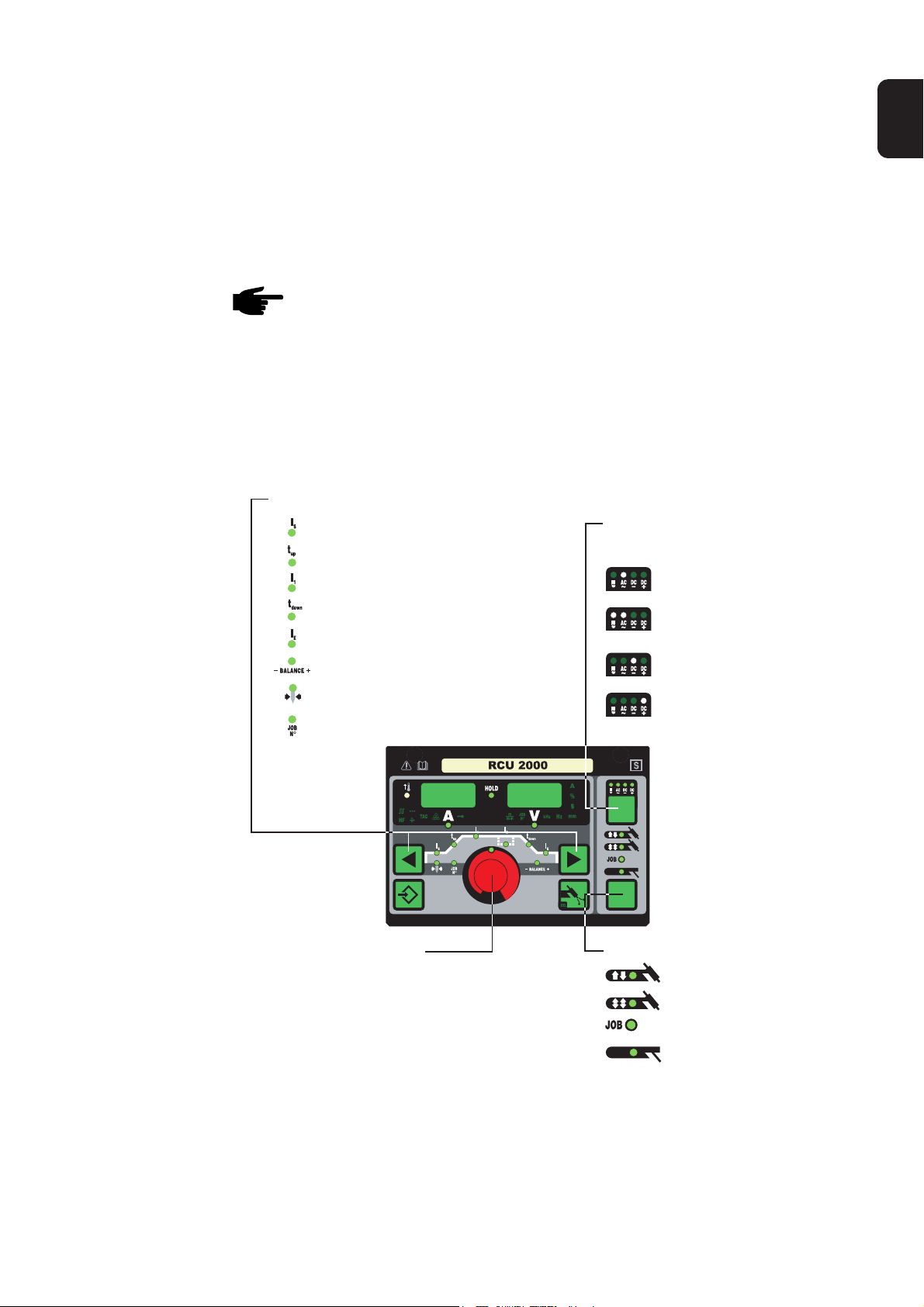
Bedienpanel
Übersicht Wesentliches Merkmal des Bedienpanels ist die logische Anordnung der Bedienelemen-
te. Alle für die tägliche Arbeit wesentlichen Parameter lassen sich einfach
- mit den Tasten anwählen
- mittels Einstellrad verändern
- während des Schweißens am Display anzeigen.
HINWEIS! Aufgrund von Softwareupdates können Funktionen an Ihrem Gerät
verfügbar sein, die in dieser Bedienungsanleitung nicht beschrieben sind oder
umgekehrt. Zudem können sich einzelne Abbildungen geringfügig von den
Bedienelementen an ihrem Gerät unterscheiden. Die Funktionsweise dieser
Bedienelemente ist jedoch identisch.
Nachfolgend dargestelltes Bild zeigt eine Übersicht der wesentlichen Einstellungen für
die tägliche Arbeit, am Beispiel des Bedienpanels MagicWave 1700/2200. Eine ausführliche Beschreibung dieser Einstellungen befindet sich in dem nachfolgenden Kapitel
„Bedienpanel“.
3. Parameter anwählen:
Startstrom I
Up-Slope t
Hauptstrom I
Down-Slope t
Endkraterstrom I
S
up
1
down
E
Balance (nur WIG-AC)
2. Verfahren anwählen:
(nur MagicWave 1700/2200)
AC Schweißen
AC + Kalottenbildung
(nur WIG)
DC- Schweißen
DE
Elektroden-Durchmesser
Job-Nummer (nur Jobbetrieb)
4. Parameter ändern
DC+ Schweißen
(nur Stabelektrode)
1. Betriebsart anwählen:
2-Takt Betrieb
4-Takt Betrieb
Job-Betrieb
Stabelektrode
3
Page 8
WARNUNG! Fehlbedienung kann schwerwiegende Personen- und Sachschäden verursachen. Beschriebene Funktionen erst anwenden, wenn folgende
Dokumente vollständig gelesen und verstanden wurden:
- diese Bedienungsanleitung
- sämtliche Bedienungsanleitungen der Systemkomponenten, insbesondere
Sicherheitsvorschriften
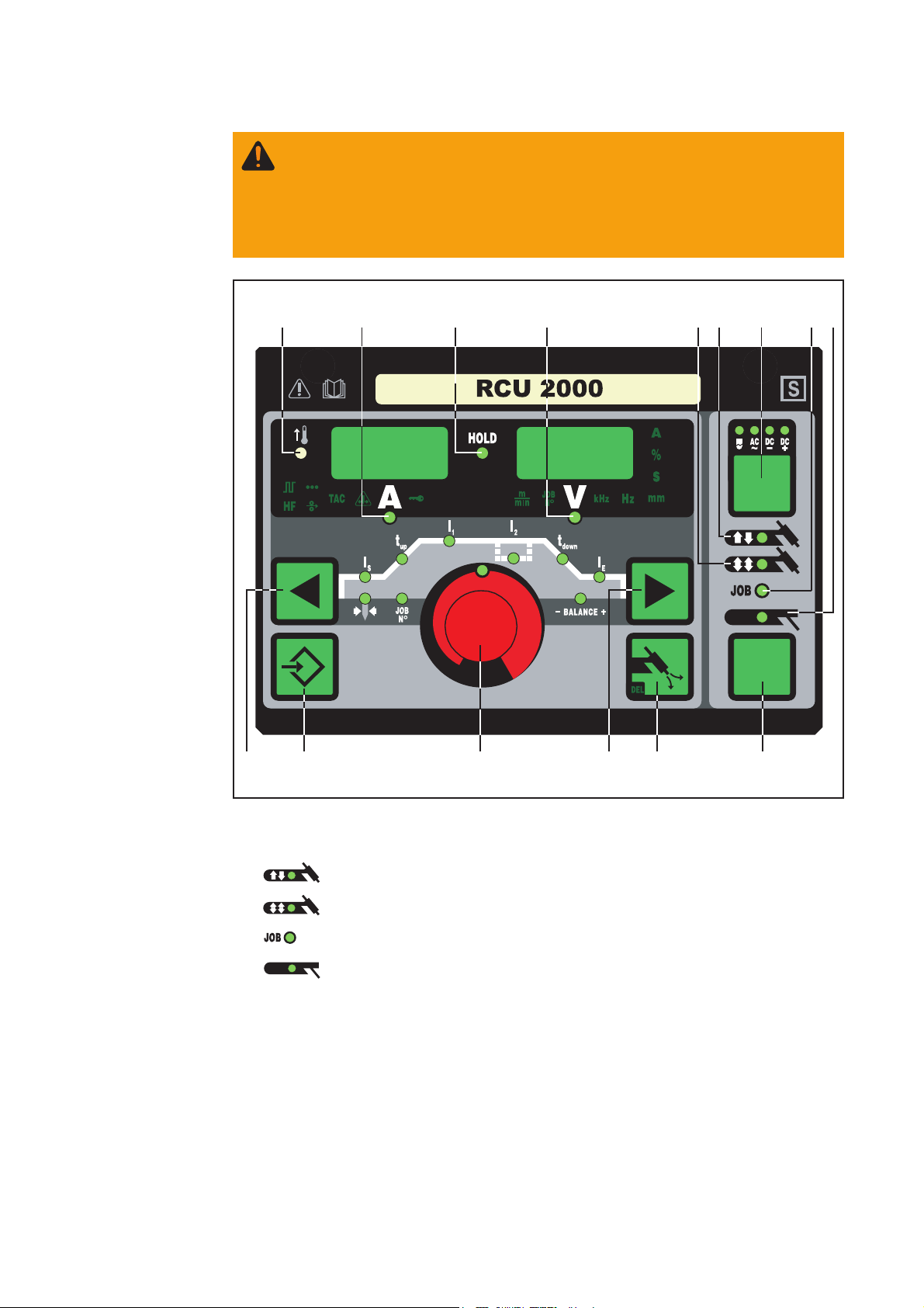
Bedienpanel RCU
2000
Das Bedienpanel der Fernbedienung RCU 2000 entspricht dem Bedienpanel der Stromquelle MW 1700/2200.
(6)(15) (12)(10) (11)
(2)(3) (5)(4)
Abb.7 Bedienpanel RCU 2000
(1) Taste Betriebsart ... zur Anwahl der Betriebsart
(2) 2-Takt Betrieb
(3) 4-Takt Betrieb
(4) Job-Betrieb
(5) Stabelektroden-Schweißen
Wichtig! Wird die Betriebsart Stabelektrodenschweißen (5) angewählt, steht die
Schweißspannung erst nach einer Verzögerung von 3 Sekunden zur Verfügung.
4
(1)(14)(9)(13)(8) (7)
Page 9
Bedienpanel RCU
2000
(Fortsetzung)
(6) Taste Verfahren ... zur Anwahl des Verfahrens, abhängig von der gewählten Be-
triebsart
DE
Betriebsart 2-Takt Betrieb / 4-Takt Betrieb gewählt:
Verfahren WIG-DC- Schweißen
Verfahren WIG-AC Schweißen
Verfahren WIG-AC Schweißen mit aktivierter Kalottenbildung
Bei gewählter Betriebsart Job-Betrieb (4) wird das für den aktuellen Job gespeicherte Verfahren angezeigt.
Betriebsart Stabelektroden-Schweißen gewählt:
Verfahren Stabelektroden-DC+ Schweißen
Verfahren Stabelektroden-DC- Schweißen
Verfahren Stabelektroden-AC Schweißen
(7) Einstellrad ... zum Ändern von Parametern. Leuchtet die Anzeige am Einstellrad ,
kann der angewählte Parameter geändert werden.
(8) und (9) Tasten Parameteranwahl ... zur Anwahl der Parameter
Ein Wechsel der Parameter mittels Tasten Parameteranwahl (8) und (9) ist auch während des Schweißens möglich.
Parameter bei angewählter Betriebsart 2-Takt Betrieb (2):
Startstrom IS.......................... 0 bis 100 % vom Hauptstrom I
1
Werkseinstellung: 35%
Wichtig! Der Startstrom IS wird für die Betriebsarten WIG-AC Schweißen und WIG
DC- Schweißen getrennt gespeichert.
Up-Slope tup.......................... 0,0 bis 9,9 s, Werkseinstellung: 0,1 s
Wichtig! Der Up-Slope t
wird für die Betriebsarten 2-Takt Betrieb und 4-Takt
up
Betrieb getrennt gespeichert.
Hauptstrom I1........................ MagicWave 1700: 3 bis 170 A
MagicWave 2200: 3 bis 220 A
Wichtig! Bei Schweißbrennern mit Up-/Down-Funktionalität kann während des
Geräte-Leerlaufes der volle Einstellbereich angewählt werden. Während des
Schweißvorganges ist eine Hauptstrom-Korrektur von +/-20 A möglich.
Down-Slope t
Wichtig! Der Down-Slope t
................... 0,0 bis 9,9 s, Werkseinstellung: 1 s
down
wird für die Betriebsarten 2-Takt Betrieb und 4-Takt
down
Betrieb getrennt gespeichert.
Endkraterstrom IE................. 0 bis 100 % vom Hauptstrom
Werkseinstellung: 30 %
5
Page 10
Bedienpanel RCU
2000
(Fortsetzung)
Balance (nur WIG-AC) .......... -5 / +5, Werkseinstellung: 0
-5 höchste Aufschmelzleistung,
geringste Reinigungswirkung
+5 höchste Reinigungswirkung,
geringste Aufschmelzleistung
Elektroden-Durchmesser .... 0 bis 4,0 mm (0.158 in.)
Werkseinstellung: 2,4 mm (0.095 in.)
Parameter bei angewählter Betriebsart 4-Takt Betrieb (3):
Startstrom IS.......................... 0 bis 100 % vom Hauptstrom I
1
Werkseinstellung: 35%
Wichtig! Der Startstrom IS wird für die Betriebsarten WIG-AC Schweißen und WIG
DC- Schweißen getrennt gespeichert.
Up-Slope tup.......................... 0,0 bis 9,9 s, Werkseinstellung: 0,1 s
Wichtig! Der Up-Slope t
wird für die Betriebsarten 2-Takt Betrieb und 4-Takt
up
Betrieb getrennt gespeichert.
Hauptstrom I1........................ MagicWave 1700: 3 bis 170 A
MagicWave 2200: 3 bis 220 A
Wichtig! Bei Schweißbrennern mit Up-/Down-Funktionalität kann während des
Geräte-Leerlaufes der volle Einstellbereich angewählt werden. Während des
Schweißvorganges ist eine Hauptstrom-Korrektur von +/-20 A möglich.
Absenkstrom I2..................... 0 bis 100 % vom Hauptstrom I
1
Werkseinstellung: 50%
Down-Slope t
Wichtig! Der Down-Slope t
................... 0,0 bis 9,9 s, Werkseinstellung: 1 s
down
wird für die Betriebsarten 2-Takt Betrieb und 4-Takt
down
Betrieb getrennt gespeichert.
Endkraterstrom IE................. 0 bis 100 % vom Hauptstrom
Werkseinstellung: 30 %
Balance (nur WIG-AC) ........ -5 / +5, Werkseinstellung: 0
-5 .... höchste Aufschmelzleistung,
geringste Reinigungswirkung
+5 ... höchste Reinigungswirkung,
geringste Aufschmelzleistung
Elektroden-Durchmesser .... 0 bis 4,0 mm (0.158 in.)
Werkseinstellung: 2,4 mm (0.095 in.)
Parameter bei angewählter Betriebsart Job-Betrieb (4):
Im Job-Betrieb stehen die Parameter zur Verfügung, welche für die im angewählten
Job gespeicherte Betriebsart gelten. Zusätzlich ist folgender Parameter verfügbar:
Job-Nummer ......................... zur Anwahl des gewünschten Jobs
6
Page 11

Bedienpanel RCU
2000
(Fortsetzung)
Parameter bei angewählter Betriebsart Stabelektroden-Schweißen (5):
Hauptstrom I1........................ MagicWave 1700: 10 bis 140 A
MagicWave 2200: 10 bis 180 A
Wichtig! Bei Schweißbrennern mit Up-/Down-Funktionalität kann während des
Geräte-Leerlaufes der volle Einstellbereich angewählt werden. Während des
Schweißvorganges ist eine Hauptstrom-Korrektur von +/-20 A möglich.
(10) Anzeige Schweißstrom ... zur Anzeige des Schweißstromes für die Parameter
IS (Startstrom)
I1 (Hauptstrom)
I2 (Absenkstrom)
IE (Endkraterstrom)
Vor Schweißbeginn zeigt die linke Anzeige den Sollwert. Für IS, I2 und IE zeigt das
rechte Display zusätzlich den %-Anteil vom Hauptstrom I1.
Nach Schweißbeginn wird der Parameter I1 automatisch angewählt. Das linke
Display zeigt den aktuellen Ist-Wert des Schweißstromes.
DE
Das Bedienpanel verdeutlicht die entsprechende Position im Schweißprozess
mittels dunkel leuchtenden Anzeigen der Parameter (IS, tup, ...).
Wichtig! Ist der Parameter ACS („Kapitel Das Setup-Menü: Ebene 2“) auf OFF
gestellt, bleibt während des Schweißens der zuletzt gewählte Parameter angewählt.
Es erfolgt keine automatische Anwahl des Parameters I1.
(11) Anzeige Schweißspannung ... zur Anzeige des aktuellen Ist-Wertes der Schweiß-
spannung an der rechten Anzeige.
Vor dem Schweißen zeigt die rechte Anzeige bei angewählten Betriebsarten für das
WIG-Schweißen „0.0“. Bei angewählter Betriebsart „Stabelektroden-Schweißen“
wird nach einer Verzögerung von 3 Sekunden der Wert für die Leerlaufspannung
„50V“ angezeigt.
Wichtig! Die Anzeige „50 V“ bei angewähltem Verfahren Stabelektroden-Schweißen
bedeutet den Mittelwert der gepulsten Leerlaufspannung.
(12) Anzeige HOLD ... bei jedem Schweißende werden die aktuellen Ist-Werte von
Schweißstrom und -spannung gespeichert - die Hold-Anzeige leuchtet.
Die Hold-Anzeige bezieht sich auf den zuletzt erreichten Hauptstrom I1. Werden
andere Parameter angewählt, erlischt die Hold Anzeige. Die Hold-Werte stehen
jedoch bei erneuter Anwahl des Parameters I1 weiterhin zur Verfügung.
Die Hold-Anzeige wird gelöscht durch
- Erneuten Schweißstart
- Einstellung des Hauptstromes I
1
- Wechsel der Betriebsart
- Wechsel des Verfahrens
Wichtig! Wurde die Hauptstromphase nie erreicht oder eine Fuß-Fernbedienung
verwendet, werden keine Hold-Werte ausgegeben.
7
Page 12

Bedienpanel RCU
2000
(Fortsetzung)
(13) Taste Store ... für das Speichern von Jobs. Dient auch zum Einstieg in das Setup-
Menü.
(14) Taste Gasprüfen ... zum Einstellen der benötigten Schutzgasmenge am Druckmin-
derer. Nach Drücken der Taste Gasprüfen strömt für 30 s Schutzgas aus. Durch
erneutes Drücken wird der Vorgang vorzeitig beendet.
(15) Anzeige Übertemperatur ... leuchtet auf, wenn sich die Stromquelle zu stark
erwärmt (z.B. infolge überschrittener Einschaltdauer). Weiterführende Informationen
finden Sie im Kapitel „Fehlerdiagnose- und Behebung“.
(38) (39) (40) (41) (42)
Die in Abb.3b dargestellten Anzeigen
leuchten, solange bestimmte Funktionen
aktiviert sind. Nachfolgende Beschreibung
gibt Ihnen einen Überblick über diese
Funktionen. Teilweise erfolgt eine noch
genauere Beschreibung bei der Detailbehandlung der jeweiligen Funktion / des
(43)(44)
Abb.8 Zusätzliche Anzeigen
entsprechenden Parameters in den
Kapiteln
- Das Setup-Menü: Ebene 1
- Das Setup-Menü: Ebene 2
- Sonderfunktionen
(38) Pulsen ist aktiviert ... Setup-Parameter „F-P“ wurde auf eine Pulsfrequenz einge-
stellt
(39) Punktieren ist aktiviert ... Setup-Parameter „SPt“ wurde auf eine Punktierzeit einge-
stellt
(40) Heften ist aktiviert ... Setup-Parameter „tAC“ wurde auf eine Zeitdauer eingestellt
(41) Anzeige „Elektrode überlastet“ ... leuchtet bei einer Überbelastung der Kalotte an
der Wolframnadel. Es besteht die Gefahr des Ausbildens einer übergroßen Kalotte.
Ursachen:
- Wolfram-Elektrode mit zu geringem Durchmesser
- Hauptstrom I1 auf einen zu hohen Wert eingestellt
- Balance zu weit in Richtung „+“ eingestellt
Abhilfe:
- Wolfram-Elektrode mit größerem Durchmesser verwenden
- Den Hauptstrom reduzieren und/oder die Balance weiter in Richtung „-“ einstellen
Wichtig! Die Anzeige „Elektrode überlastet“ (41) ist exakt auf folgende WolframElektroden abgestimmt:
- WIG-AC Schweißen: Reinwolfram-Elektroden
- WIG-DC Schweißen: Cerierte Elektroden
Für alle anderen Elektroden gilt die Anzeige „Elektrode überlastet“ (41) als Richtwert
(42) Anzeige „Tastensperre aktiviert“ ... leuchtet bei aktivierter Tastensperre, gemäß
Kapitel „Sonderfunktionen“
(43) Kaltdraht-Vorschub ist angeschlossen ... leuchtet bei angeschlossenem Kaltdraht-
Vorschub
(44) HF-Zünden (Hochfrequenz-Zünden) ist aktiviert ... Setup-Parameter „HFt“ wurde auf
ein Intervall für die Hochfrequenz-Impulse eingestellt
8
Page 13

Dear Reader
Introduction
Thank you for choosing Fronius - and congratulations on your new, technically highgrade Fronius product! This instruction manual will help you get to know your new
machine. Read the manual carefully and you will soon be familiar with all the many
great features of your new Fronius product. This really is the best way to get the most
out of all the advantages that your machine has to offer.
Please also take special note of the safety rules - and observe them! In this way, you
will help to ensure more safety at your product location. And of course, if you treat your
product carefully, this definitely helps to prolong its enduring quality and reliability - things
which are both essential prerequisites for getting outstanding results.
EN
ud_fr_st_et_00493 01/2012
Page 14

Page 15

General Informations
Product concept
System requirements
The RCU 2000 remote control unit allows
you to remote-operate a power source
which is located e.g. inside a production
R
C
U
2
0
0
0
cell - for set-up purposes, for example.
The functions available on the remote
control unit correspond to those on the
control panel of the MagicWave 1700/
2200 power source.
Fig.1. RCU 2000 remote control unit
The RCU 2000 remote control unit can be operated in conjunction with the following
power sources:
- MagicWave 1700/2200
- MagicWave 2500/3000
- MagicWave 4000/5000
- TransTig 2200
- TransTig 2500/3000
- TransTig 4000/5000
- TransPocket 4000/5000
- TransSynergic 4000/5000
- TransPuls Synergic 2700/3200/4000/5000
EN
Important! If the TransTig 2200 power source is operated by the RCU 2000 remote
control unit, the following buttons and indicators will be disabled:
- “Process” button
- “Balance” parameter
Important! All controls and display elements for HF ignition (high-frequency ignition) are
disabled, when one of the following power sources is controlled using the RCU 2000
remote control unit.
- TransPocket 4000/5000
- TransSynergic 4000/5000
- TransPuls Synergic 2700/3200/4000/5000
1
Page 16

Connecting up
the remote
control unit
Insert the plug at the end of the remote-control cable into the LocalNet connection
socket (A).
(A)
(A)
Keylock switch
Fig.2 Front view MW/TT 1700/2200
Fig.3 Front view TPS 2700
(A)
(A)
Fig.4 Rear viewTS/TPS 3200/4000/5000 Fig.5 Front view TP 4000/5000
NOTE! When the keylock switch
is in the horizontal position (B), all
the buttons on the control panel
are disabled:
- The “key” symbol (C) is lit up on the
control panel
- If you still press any of the buttons,
the disabled message “Clo|SEd” will
briefly appear on the displays. The
only parameter that it is possible to
alter (with the adjusting dial) is the
one that was already selected at the
(C)
Fig.6 Keylock switch
(B)
time the keylock was activated.
2
Page 17

Control panel
Overwiew
The key feature of the control panel is the logical way in which the controls are arranged.
All the main parameters needed for day-to-day working can easily be
- selected with the buttons
- altered with the adjusting dial
- shown on the display during welding.
NOTE! Owing to software updates, you may find that your machine has certain
functions that are not described in these Operating Instructions, or vice-versa.
Also, certain illustrations may be very slightly different from the actual controls
on your machine. However, these controls function in exactly the same way.
The illustration below shows an overview of the main settings needed for day-to-day
working, based on the example of the MagicWave 1700/2200 control panel. You will find
a detailed description of these settings in the following section (“Control panel”).
3. Select the parameter:
Starting current I
Upslope t
up
Main current I
Downslope t
Final current I
S
1
down
E
Balance (only with TIG-AC)
2. Choose which process:
(only on MagicWave 1700/2200)
AC welding
AC + cap-shaping
(only with TIG)
DC- welding
EN
Electrode diameter
Job number (only in Job Mode)
4. Alter the parameter
DC+ welding
(only with rod electrode)
1. Select the operating mode:
2-step mode
4-step mode
Job mode
Rod electrode (MMA)
3
Page 18

WARNING! Operating the equipment incorrectly can cause serious injury and
damage. Do not use the functions described here until you have read and
completely understood all of the following documents:
- these Operating Instructions
- all "Operating Instructions" for the system components, especially the
"Safety rules"
RCU 2000 control
panel
The RCU 2000 control panel correspond to the control panel of the MagicWave 1700/
2200 power source.
(6)(15) (12)(10) (11)
(2)(3) (5)(4)
Fig.7 RCU 2000 control panel
(1) Mode button ... for selecting the operating mode:
(2) 2-step mode
(3) 4-step mode
(4) Job mode
(5) Rod electrode (MMA) welding
Important! If you select the “Rod electrode (MMA) welding” mode (5), the welding
voltage will only be available after a 3-second time-lag.
4
(1)(14)(9)(13)(8) (7)
Page 19

RCU 2000 control
panel
(continued)
(6) Process button ... for selecting the process, depending upon which operating
mode has been selected
If 2-step / 4-step mode has been selected:
TIG-DC- welding
TIG-AC welding
TIG-AC welding with activated cap-shaping function
If “Job mode” (4) has been selected, the display shows the process that was saved
for the current job.
If “Rod electrode (MMA) welding mode” (5) has been selected:
Rod electrode DC+ welding
Rod electrode DC- welding
Rod electrode AC welding
(7) Adjusting dial ... for altering parameters. If the indicator is lit up on the adjusting
dial, then the selected parameter can be altered.
(8) and (9) Parameter selection buttons ... for selecting the parameters
EN
It is also possible to change parameters by means of the parameter selection buttons (8)
and (9) while the welding operation is in progress.
Available parameters where 2-step mode (2) has been selected:
Starting current IS................. 0 to 100 % of main current I
1
Factory setting: 35%
Important! The starting current IS is saved separately for the “TIG-AC welding” and
“TIG DC- welding” operating modes.
Upslope tup............................ 0.0 to 9.9 s, factory setting: 0.1 s
Important! The upslope t
is saved separately for the 2-step and 4-step operating
up
modes.
Main current I1...................... MagicWave 1700: 3 to 170 A
MagicWave 2200: 3 to 220 A
Important! On welding torches with Up/Down functionality, the entire setting range
is available for selection while the machine is idling. During welding, the main
current can be corrected by +/-20 A.
Downslope t
.................... 0.0 to 9.9 s, factory setting: 1 s
down
Important! The downslope t
is saved separately for the 2-step and 4-step
down
operating modes.
Final current IE...................... 0 to 100 % of main current
Factory setting: 30 %
5
Page 20

RCU 2000 control
panel
(continued)
Balance (only with TIG-AC) ... -5 / +5, factory setting: 0
-5 highest fusing power,
lowest cleaning action
+5 highest cleaning action,
lowest fusing power
Electrode diameter ............... 0 to 4.0 mm, factory setting: 2.4 mm
Available parameters where 4-step mode (3) has been selected:
Starting current IS................. 0 to 100 % of main current I
1
Factory setting: 35%
Important! The starting current IS is saved separately for the “TIG-AC welding” and
“TIG DC- welding” operating modes.
Upslope tup............................ 0.0 to 9.9 s, factory setting: 0.1 s
Important! The upslope t
is saved separately for the 2-step and 4-step operating
up
modes.
Main current I1...................... MagicWave 1700: 3 to 170 A
MagicWave 2200: 3 to 220 A
Important! On welding torches with Up/Down functionality, the entire setting range
is available for selection while the machine is idling. During welding, the main
current can be corrected by +/-20 A.
Reduced current I2............... 0 to 100 % of main current I
1
Factory setting: 50%
Downslope t
Important! The downslope t
.................... 0.0 to 9.9 s, factory setting: 1 s
down
is saved separately for the 2-step and 4-step
down
operating modes.
Final current IE...................... 0 to 100 % of main current
Factory setting: 30 %
Balance (only with TIG-AC) . -5 / +5, factory setting: 0
-5 .... highest fusing power,
lowest cleaning action
+5 ... highest cleaning action,
lowest fusing power
Electrode diameter ............... 0 to 4.0 mm, (0.158 in.)
factory setting: 2.4 mm (0.095 in.)
Available parameters where “Job mode” (4) has been selected:
In “Job mode”, the parameters that apply to the operating mode that has been
stored in the selected job are made available. In addition, the following parameter is
also available:
Job number .......................... for selecting the desired job
Available parameters where the “Rod electrode (MMA) welding” mode (5) has been
selected:
6
Page 21

RCU 2000 control
panel
(continued)
Main current I1...................... MagicWave 1700: 10 to 140 A
MagicWave 2200: 10 to 180 A
Important! On welding torches with Up/Down functionality, the entire setting range
is available for selection while the machine is idling. During welding, the main
current can be corrected by +/-20 A.
(10) Welding current display ... for indicating the welding current for the parameters:
IS (starting current)
I1 (main current)
I2 (reduced current)
IE (final current)
Before the start of welding, the left-hand display shows the command value. For IS,
I2 and IE , the right-hand display also shows the respective %-age of the main
current I1.
After the start of welding, the parameter I1 is automatically selected. The left-hand
display shows the present actual value of the welding current.
The control panel indicates which position has been reached in the welding process
by means of a dimmed display of the parameters (IS, tup, ...).
Important! If the parameter ACS (see the section headed “Set-up menu: Level 2”) is
set to OFF, then the most recently selected parameter remains active during welding. No automatic selection of parameter I1 takes place.
EN
(11) Welding voltage display ... for indicating the actual welding-voltage value on the
right-hand display.
Where one of the TIG-welding modes has been selected, the right-hand display
reads “0.0” before the start of welding. Where the “Rod electrode (MMA) welding”
mode has been selected, there is first a 3-second time-lag, after which the value for
the open-circuit voltage “50V” is displayed.
Important! The value of 50 V indicated where the “Rod electrode (MMA)” process
has been selected refers to the mean value of the pulsed open-circuit voltage.
(12) HOLD indicator ... every time you finish a welding operation, the actual values for
welding current and voltage are stored, and the “Hold” indicator lights up.
The “Hold” indicator refers to the last value reached by the Main current I1. As soon
as any other parameter is selected, the “Hold” indicator goes out. The “Hold” values
will continue to be available, however, if Parameter I1 is selected once again.
The “Hold” indicator is cancelled whenever:
- a new welding operation is started
- the Main current I1 is adjusted
- the operating mode is changed
- the process is changed
Important! If the main-current phase was never reached, or if a pedal remotecontrol unit was being used, no “Hold” values are outputted.
7
Page 22

RCU 2000 control
panel
(continued)
(13) Store button ... for storing jobs. Is also used for accessing the Set-up menu.
(14) Gas-test button ... for setting the required gas-flow rate on the pressure regulator.
After you press this button, gas will flow out for 30 s. Press the button again to stop
the gas test-flow before the 30 seconds are up.
(15) Overtemperature indicator ... lights up if the power source overheats (e.g. becau-
se the duty cycle has been exceeded). For more information on this, see the “Troubleshooting” section.
(38) (39)
(40) (41) (42)
The indicators shown in Fig.3b glow for as
long as the respective functions remain
activated. The following description will
give you an overview of these functions. In
some cases, they will be described in even
greater detail in the in-depth sections
dealing with the function or parameter in
(43)(44)
Fig.8 Additional indicators
question, to be found in:
- The set-up menu: Level 1
- The set-up menu: Level 2
- Special functions
(38) Pulsing is activated ... Set-up parameter “F-P” has been set to a certain pulsing
frequency
(39) Spot welding is activated ... Set-up parameter “SPt” has been set to a certain spot-
welding time
(40) Tacking is activated ... Set-up parameter “tAC” has been set to a certain duration
(41) “Electrode overload“ indicator ... lights up when the cap at the tip of the tungsten
electrode is overloaded. This means that there is a risk of an excessively large cap
being formed.
Causes:
- The tungsten electrode does not have a large enough diameter
- Main current I1 has been set to too high a value
- “Balance” has been set too far towards “+”
Remedies:
- Use a tungsten electrode with a bigger diameter
- Reduce the main current and/or set “Balance” further towards “-”
Important! The “Electrode overload“ indicator (41) is fine-tuned to work with the
following tungsten electrodes:
- TIG-AC welding: Pure tungsten electrodes
- TIG-DC welding: Ceriated electrodes
For all other electrodes, the “Electrode overload” indicator (41) must be taken as a
guideline only
(42) “Keylock activated” indicator ... lights up when the keylock is activated, as described
in the section headed “Special functions”
(43) Cold-wire feeder is connected ... This indicator lights up when a cold-wire feeder is
connected
(44) HF (high-frequency) ignition is activated ... Set-up parameter “HFt” has been set to
a certain interval for the high-frequency impulses
8
Page 23

Cher lecteur
Introduction
Nous vous remercions de votre confiance et vous félicitons d’avoir acheté un produit de
qualité supérieure de Fronius. Les instructions suivantes vous aideront à vous familiariser avec le produit. En lisant attentivement les instructions de service suivantes, vous
découvrirez les multiples possibilités de votre produit Fronius. C’est la seule manière
d’exploiter ses avantages de manière optimale.
Prière d’observer également les consignes de sécurité pour garantir une sécurité accrue
lors de l’utilisation du produit. Une utilisation soigneuse du produit contribue à sa longévité et sa fiabilité. Ce sont des conditions essentielles pour obtenir d’excellents résultats.
FR
ud_fr_st_et_00500 01/2012
Page 24

Page 25

Généralités
Concept de
produit
Conditions à
remplir par le
système
La télécommande RCU 2000 permet
l’exploitation à distance d’une source de
courant. L’exploitation à distance peut par
R
C
U
2
0
0
0
exemple servir au réglage de sources de
courant dans des cellules d’usinage. Les
fonctions de la télécommande correspondent au panneau de commande de la
source de courant MagicWave 1700/2200.
Fig.1 Télécommande RCU 2000
Le fonctionnement de la télécommande est possible en liaison avec les sources de
courant suivantes:
- MagicWave 1700/2200
- MagicWave 2500/3000
- MagicWave 4000/5000
- TransTig 2200
- TransTig 2500/3000
- TransTig 4000/5000
- TransPocket 4000/5000
- TransSynergic 4000/5000
- TransPuls Synergic 2700/3200/4000/5000
FR
Important! Dans le cas où la source de courant TransTig 2200 serait commandée
depuis la télécommande RCU 2000, les éléments de commande/d’affichage suivants
seraient hors service.
- Touche «procédé»
- Paramètre «Balance»
Important! Tous les indicateurs et organes de commande de l’amorçage haute fré-
quence (amorçage HF) sont hors function, lorsque les générateurs de soudage suivants
sont commandés à partir de la télécommande RCU 2000 :
- TransPocket 4000/5000
- TransSynergic 4000/5000
- TransPuls Synergic 2700/3200/4000/5000
11
Page 26

Raccordement de
la télécommande
Brancher la fiche du câble de la télécommande à la douille de raccordement LocalNet (A).
(A)
(A)
Fig.2 Vue de face - MW/TT 1700/2200
Fig.3 Vue de face - TPS 2700
(A)
(A)
Fig.4 Vue de dos - TS/TPS 3200/4000/5000
Fig.5 Vue de face - TP 4000/5000
Interrupteur à clé Remarque! Quand l’interrupteur
à clé est en position horizontale
(B), toutes les touches du panneau de commande sont verrouillées:
- L’icône représentant une clé (C) est
allumé au panneau de commande.
- Si on appuie toutefois sur une touche,
le message de verrouillage «Clo|SEd»
s’affiche aux voyants. Seul le paramètre qui était sélectionné au
moment du verrouillage des touches
(B)(C)
Fig.6 Interrupteur à clé
peut être modifié au moyen de la
molette de réglage.
22
Page 27

Panneau de commande
Aperçu La disposition logique du panneau de commande en constitue une caractéristique
essentielle. Tous les paramètres significatifs pour le travail quotidien peuvent être
- sélectionnés au moyen des touches
- modifiés au moyen d’une molette de réglage
- être affichés à l’écran pendant le soudage.
Remarque: En raison de mises à jour de logiciel, il est possible que certaines
fonctions non décrites dans le présent manuel soient disponibles sur votre
appareil ou inversement. De plus, certaines illustrations peuvent présenter de
légères différences avec les éléments de commande de votre appareil.Le mode
de fonctionnement est cependant identique.
L’illustration ci-dessous donne un aperçu des réglages principaux pour le travail quotidien d’après l’exemple du panneau de commande MagicWave 1700/2200. Vous trouverez
une description détaillée de ces réglages au chapitre suivant «Panneau de commande».
3. Sélection des paramètres
Courant de départ I
Up-Slope t
up
Courant principal I
Down-Slope t
Courant cratère final I
S
1
down
E
Equilibre (TIG-AC seulement)
Diamètre de l’électrode
N° de tâche (mode tâches seulement)
2. Sélection du procédé
(MagicWave 1700/2200 seulement)
Soudage AC
AC+formation de calotte
(TIG seulement)
Soudage DC-
Soudage DC+
(électrode en baguette
seulement)
FR
4. Modification des
paramètres
1. Sélection du mode de service
mode à 2 temps
mode à 4 temps
Mode tâches
Electrode en baguette
33
Page 28

Avertissement! Les erreurs de manipulation peuvent entraîner des dommages
corporels et matériels graves. N’utilisez les fonctions décrites qu’après avoir lu
et compris l’intégralité des documents suivants:
- le présent mode d’emploi
- tous les modes d’emploi des composants du système, en particulier les
consignes de sécurité
Panneau de
commande RCU
2000
Les fonctions de la télécommande RCU 2000 correspondent au panneau de commande
de la source de courant MagicWave 1700/2200.
(6)(15) (12)(10) (11)
(2)(3) (5)(4)
Fig.7 Panneau de commande
(1) Touche mode de service... sert à la sélection du mode de service
(2) mode à 2 temps
(3) modeà 4 temps
(4) Mode tâches
(5) Soudage aux électrodes en baguette
Important! En cas de sélection du mode de service Soudage à l’électrode en
baguette, la tension de soudage n’est disponible qu’après un décalage de 3 secondes.
44
(1)(14)(9)(13)(8) (7)
Page 29

Panneau de
commande RCU
2000
(suite)
(6) Touche procédé ... pour la sélection du procédé, en fonction du mode de service
sélectionné
Mode de service à 2 temps/service à 4 temps sélectionné:
Procédé soudage TIG-DC
Procédé soudage TIG-AC
Procédé soudage TIG-AC avec formation de calotte activée
Le procédé enregistré pour la tâche en cours est affiché en mode de service
Tâches (4)
Mode de service soudage à l’électrode en baguette:
Procédé soudage à l’électrode en baguette DC+
Procédé soudage à l’électrode en baguette DC-
Procédé soudage à l’électrode en baguette AC
FR
(7) Molette de réglage... sert à la modification des paramètres. Quand le voyant de la
molette de réglage est allumé, il est possible de modifier le paramètre sélectionné.
(8) et (9) Touches Sélection des paramètres .. pour la sélection des paramètres
Il est possible de modifier les paramètres pendant le soudage au moyen des touches
Sélection des paramètres (8) et (9).
Paramètres avec mode de service à 2 temps (2) sélectionné:
Courant de départ IS............. 0 à 100% du courant principal I
1
Réglage usine: 35%
Important! Le courant de départ IS se mémorise séparément pour les modes de
service TIG-AC et TIG-DC.
Up-Slope tup.......................... 0,0 à 9,9 sec, réglage usine: 0,1 sec
Important! Up-Slope t
se mémorise séparément pour les modes de service à 2
up
temps et à 4 temps.
Courant principal I1.............. MagicWave 1700: 3 à 170 A
MagicWave 2200: 3 à 220 A
Important! Pour les chalumeaux à fonction Up/Down, il est possible de sélectionner toute la gamme de réglage pendant la marche à vide de l’appareil. Pendant le
processus de soudage, on peut corriger le courant principal de +/- 20A.
Down-Slope t
Important! Down-Slope t
................... 0,0 à 9,9 sec, réglage usine 1 sec
down
se mémorise séparément pour les modes de service à
down
2 temps et à 4 temps.
Courant de cratère final IE... 0 à 100% du courant principal
Réglage usine: 30%
55
Page 30

Panneau de
commande RCU
2000
(suite)
Equilibre (TIG-AC slt) ........... -5 / +5, réglage usine: 0
-5 plus grande puissance de soudage par
fusion, plus petit effet nettoyant
+5 plus grand effet nettoyant,
plus petite puissance de soudage par fusion.
Diamètre de l’électrode ....... 0 bis 4,0 mm, réglage usine: 2,4 mm
Paramètres avec le mode de service à 4 temps sélectionné (3):
Courant de départ IS............. 0 bis 100 %du courant principal I
1
réglage usine : 35%
Important! Le courant de départ IS s’enregistre séparément pour les modes de
service soudage TIG-AC et TIG-DC.
Up-Slope tup.......................... 0,0 à 9,9 s, réglage usine : 0,1 s
Important! Up-Slope t
s’enregistre séparément pour les modes de service à 2
up
temps et 4 temps.
Courant principal I1............. MagicWave 1700: 3 à 170 A
MagicWave 2200: 3 à 220 A
Important! Pour les chalumeaux à fonction Up/Down, il est possible de sélectionner toute la gamme de réglage pendant la marche à vide de l’appareil. Pendant le
processus de soudage, on peut corriger le courant principal de +/- 20A.
Courant de descente I2........ 0 à 100 % du courant principal I
1
Réglage usine: 50%
Down-Slope t
Important! Down-Slope t
................... 0,0 à 9,9 sec, réglage usine: 1 sec
down
s’enregistre séparément pour les modes de service à 2
down
temps et à 4 temps.
Courant de cratère final IE... 0 à 100 % du courant principal
réglage usine: 30 %
Equilibre (TIG-AC slt) ........ -5 / +5, réglage usine: 0
-5 .... plus grande puissance de soudage
par fusion, plus petit effet nettoyant
+5 ... plus grand effet nettoyant,
plus petite puissance de soudage par
fusion
Diamètre des électrodes...... 0 à 4,0 mm (0.0158 in.)
réglage usine: 2,4 mm (0.095 in.)
Paramètres avec le mode de service Tâches sélectionné (4):
En mode de service Tâches, les paramètres valables enregistrés pour le mode de
service enregistré dans la tâche sélectionnée sont disponibles.
N° de tâche ........................... pour la sélection de la tâche souhaitée
Paramètres avec le mode de service Soudage à l’électrode en baguette (5) sélectionné:
66
Page 31

Panneau de
commande RCU
2000
(suite)
Courant principal I1.............. MagicWave 1700: 10 à 140 A
MagicWave 2200: 10 à 180 A
Important! Pour les chalumeaux à fonction Up/Down, il est possible de sélectionner toute la gamme de réglage pendant la marche à vide de l’appareil. Pendant le
processus de soudage, on peut corriger le courant principal de +/- 20A.
(10) Voyant de soudage ... sert à afficher le courant de soudage pour les paramètres
IS (cournant de départ)
I1 (Courant principal)
I2 (Courant de descente )
IE (Courant de cratère final)
L’écran de gauche montre la valeur de consigne avant le début du soudage. Pour IS,
I2 und IE l’écran de droite montre aussi le pourcentage du courant principal I1.
Après le début du soudage, le paramètre I1 est sélectionné automatiquement.
L’écran de gauche affiche la valeur effective actuelle du courant de soudage.
Le panneau de commande permet de voir la position correspondante dans le cadre
du processus de soudage en affichant les paramètres (IS, tup, ...) à des voyants à
faible éclairage.
Important! Si le paramètre ACS (Chapitre «Menu Setup: niveau 2») a été réglé sur
OFF, le dernier paramètre sélectionné pendant le soudage reste sélectionnée. Le
paramètre I1n’est pas sélectionné automatiquement.
(11) Affichage de la tension de soudage.. sert à l’affichage de la valeur effective
actuelle de la tension de soudage à l’écran de droite.
L’écran de droite affiche «0,0» avant le soudage, les modes de service étant sélectionés pour le soudage TIG. Quand le mode de service «Soudage à l’électrode en
baguette» a été sélectionnée, la valeur pour la tension à vide «50V» s’affiche avec
un décalage de 3 secondes.
Important! L’affichage «50V» est la valeur moyenne de la tension à vide pulsée
quand la procédure Soudage à l’électrode en baguette a été sélectionnée.
FR
(12)Voyant HOLD ... Les valeurs effectives actuelles du courant et de la tension de
soudage sont enregistrées à chaque arrêt de soudage - le voyant HOLD est allumé.
Le voyant HOLD se rapporte au dernier courant principal atteint I1. Si l’on sélectionne d’autres paramètres, le voyant Hold s’éteint. Toutefois, les valeurs hold
restent disponibles chaque fois qu’on sélectionne le paramètre I1 à nouveau.
Le voyant Hold disparaît
- à un nouveau démarrage du soudage
- au réglage du courant principal I
1
- au changement du mode de service
- au changement de procédé
Important! Les valeurs Hold ne sont pas émises quand la phase de courant principal n’a jamais été atteinte ou qu’on utilise une télécommande à pédale.
(13) Touche Store ... sert à l’enregistrement de tâches. Sert également à l’accès au
menu Setup
77
Page 32

Panneau de
commande RCU
2000
(suite)
(14) Touche contrôle du gaz ... sert au réglage de la quantité de gaz protecteur requis
au réducteur de pression. Après avoir appuyé sur la touche Contrôle du gaz, du gaz
protecteur fuse pendant 30 sec. Appuyer à nouveau sur la touche pour interrompre
le processus prématurément.
(15) Voyant excédent de température... s’allume quand la source de courant est
surchauffée (par ex. en raison du dépassement du temps de fonctionnement). Vous
trouverez des informations complémentaires au chapitre «Diagnostic des défauts et
élimination».
(38) (39)
(40) (41) (42)
Les voyants représentés à la fig. 8 sont
allumés tant que certaines fonctions sont
activées. La description ci-après vous
donne un aperçu de ce fonctions. Vous
trouverez une description encore plus
précise au traitement en détail de la
fonction correspondante/du paramètre
(43)(44)
Fig.8 Voyants supplémentaires
correspondant aux chapitres
- Le menu Setup: niveau 1
- Le menu Setup: niveau 2
- Fonctions spéciales
(38) Le mode pulsé est activé ... le paramètre Setup «F-P» a été réglé sur une fréquence
d’impulsions
(39) Soudage par points est activé ... Le paramètre Setup «SPt» a été réglé sur un
temps de soudage par points
(40) Pointer est activé... Le paramètre Setup «tAC» a été réglé sur une durée
(41) Voyant «Electrode surchargée» ... allumé en cas de surcharge de la calotte à
l’aiguille en tungstène. Danger de formation d’une calotte surdimensionnée.
Causes:
- Electrode en tungstène a diamètre trop faible
- Courant principal I1 réglé sur une valeur trop élevée
- Balance réglée trop loin en direction de «+»
Remède:
- Utiliser une électrode en tungstène de diamètre plus important
- Réduire le courant principal et ou/ régler Balance davantage en direction de «-»
Important! Le voyant «Electrode surchargée» (41) est coordonné exactement aux
électrodes en tungstène suivantes:
- Soudage TIG-AC: électrodes en tungstène pur
- Soudage TIG-DC: électrodes contenant du cérium
Pour toutes les autres électrodes, le voyant «électrode surchargée» a une valeur
indicative
(42) Voyant «Blocage des touches activé» ... allumé quand le verrouillage des touches
est activé, suivant chapitre «Fonctions spéciales»
(43) Dévidoir à fil-électrode froid raccordé ... allumé quand un dévidoir à fil électrode
froid est raccordé
(44) Amorçage HF (haute fréquence) activé ... le paramètre Setup «HFt» a été réglé sur
un intervalle pour les impulsions haute fréquence.
88
Page 33

RCU 2000 - 4,046,089
43,0001,3259
42,0406,0093
42,0406,0315
42,0407,0478
42,0409,2937
42,0201,1417
42,0407,0481
42,0400,0105
43,0002,0320
42,0200,9756
42,0201,1419
BE2,0201,1416
4,070,674 - NT485
NT485
42,0201,1418
42,0405,0267
42,0300,0607
40,0003,0348*
* gewünschte Länge angeben
* Specify the length required
* Indiquer la longueur désirée
43,0003,0690
* Indicar la longitud deseada
* Indicare la lunghezza desiderat
* indicar o comprimento desejado
RCU 2000
Ersatzteilliste / Spare parts list / Listes de pièces de rechange / Lista de repuestos / Lista de pecas sobresselentes / Lista dei Ricambi
el_fr_st_fb_00547 012002
/1
1
Page 34

FRONIUS INTERNATIONAL GMBH
Froniusplatz 1, A-4600 Wels, Austria
Tel: +43 (0)7242 241-0, Fax: +43 (0)7242 241-3940
E-Mail: sales@fronius.com
www.fronius.com
Under http://www.fronius.com/addresses you will find all addresses
www.fronius.com/addresses
of our Sales & service partners and Locations.
ud_fr_st_so_00082 012011
 Loading...