

Page 1

Installation
Instructions
Rapid Shutdown Box - Duo
Rapid Shutdown Box - Quattro
Rapid Shutdown Box - Duo
Rapid Shutdown Box - Quattro
Rapid Shutdown Box - Duo
Rapid Shutdown Box - Quattro
EN-US
FR
ES-MX
Installation instructions
Instructions d'installation
Instrucciones de instalación
42,0410,2331 009-04112022
Page 2

Page 3

Table of contents
General 4
PHOTOVOLTAIK (PV) SYSTEM EQUIPPED WITH RAPID SHUTDOWN 4
Safety 4
FCC / RSS Compliance 5
Device concept 6
System Limitations 6
Maximum Distance Between the Rapid Shutdown Box and the PV Array 6
Technical Data 7
Compatibility with Inverters 7
Service code 307 on the SnapInverter series 8
Service Code 1175 on the GEN24 inverter series 9
Triggering a rapid shutdown 9
Performing a reset after a rapid shutdown 10
Self-test 10
Installing the Rapid Shutdown Box 11
Drilling pattern 12
Mounting the Rapid Shutdown Box - Duo on a rail 12
Attaching the Rapid Shutdown Box to the wall 13
Connecting the Rapid Shutdown Box 14
Wiring of the Rapid Shutdown Box - Duo 14
Connecting the wires Rapid Shutdown Box - Quattro 15
Connecting a MC4-Y-Connector 16
Connecting several Rapid Shutdown Boxes 16
Connecting the wires to the Terminals 17
Connecting the Rapid Shutdown Box to a SnapINverter 17
Connecting the Rapid Shutdown Box to GEN24 Inverter 18
Connecting the Rapid Shutdown Box Grounding 19
SnapINverter: Connecting the Rapid Shutdown Box to an emergency stop button 20
GEN24 inverter: Connecting the Rapid Shutdown Box to an emergency stop button 21
Connecting the Rapid Shutdown Box to a Fronius Primo 10.0 / 11.4 / 12.5 / 15.0 21
Connecting the Rapid Shutdown Box to a Fronius Primo GEN24 208-240 22
EN-US
3
Page 4

General
PHOTOVOLTAIK
(PV) SYSTEM
EQUIPPED
WITH RAPID
SHUTDOWN
Safety
According to the standard CSA C22.2 No.330-17, this product was developed as
a part of a “PHOTOVOLTAIK (PV) SYSTEM EQUIPPED WITH RAPID SHUT-
DOWN”.
WARNING!
Incorrect operation and incorrectly performed work can cause serious injury
and property damage.
Only qualified staff are authorized to commission the Rapid Shutdown Box (RSB)
and only within the scope of the respective technical regulations. Do not start up
or carry out maintenance work until you have read the safety rules.
WARNING!
Work performed incorrectly can cause serious injury and damage.
The Rapid Shutdown Box should only be installed and connected by licensed
electricians.
Follow the safety rules!
Before any installation or connection work is carried out, disconnect the AC supply to the inverter and the DC supply to the Rapid Shutdown Box.
WARNING!
An electric shock can be fatal.
Inadequately sized electrical components can cause serious injury and damage
to property.
All electrical connections must be made in accordance with the National
▶
Electrical Code, ANSI/NFPA 70, and any other regulations applicable to the
installation site.
Installations in Canada must be carried out in accordance with applicable
▶
Canadian standards.
Only use copper wires for all spring-type terminals.
▶
For all grounding cables and DC grounding wires, use a suitable thermal
▶
class, min. 194 °F (90 °C).
See NEC table 250.122 for correct dimensioning of the grounding wires
▶
Voltage drop and other considerations may mean larger cable cross sections
▶
need to be used.
WARNING!
An inadequate ground conductor connection can cause serious injury and damage to property.
The housing screws provide an adequate ground conductor connection for
grounding the housing and should not be replaced under any circumstances by
other screws that do not provide a reliable ground conductor connection.
4
Page 5

CAUTION!
(1)
(1)
The following points must be observed in order to prevent damage to the Rapid
Shutdown Box:
The technical specifications must be followed.
▶
The pressure compensation membrane (1) should never be used for cabling.
▶
Rapid Shutdown Box - Duo
NOTE!
Solar modules exposed to light supply current to the Rapid Shutdown Box if
they are connected.
NOTE!
Rapid Shutdown Box - Quattro
EN-US
FCC / RSS Compliance
When installing outdoors, only use waterproof conduit fittings and conduits.
Conduit fittings and conduits are not included in the Rapid Shutdown Box's
scope of supply. Conduit fittings must always be installed with a locknut. Ensure
that the conduit fittings are installed and sealed correctly.
NOTE!
When connecting DC cables, ensure the polarity is correct.
IMPORTANT!
The trigger device (inverter) of the Rapid Shutdown Box must be marked to
clearly identify the status of the Rapid Shutdown Box.
If the Rapid Shutdown Box loses the AC connection, the inverter becomes the
trigger and display device.
FCC
This device corresponds to the limit values for a digital device of class B in accordance with Part 15 of the FCC regulations. The limit values should provide
adequate protection against harmful interference in homes. This device creates
and uses high frequency energy and can interfere with radio communications
when not used in accordance with the instructions. However, there is no guarantee against interference occurring in a particular installation.
If this device interferes with radio or television reception when turning the device
on and off, it is recommended that the user solve this with one or more of the
following measures:
5
Page 6

adjust or reposition the receiving antenna
-
increase the distance between the device and the receiver
-
connect the device to another circuit, which does not include the receiver
-
for further support, please contact the retailer or an experienced radio/TV
-
technician.
Industry Canada RSS
The device corresponds to the license-free Industry Canada RSS standards. Operation is subject to the following conditions:
(1) The device may not cause harmful interference
(2) The device must accept any interference received, including interference that
may cause undesired operation.
Device concept The Rapid Shutdown Box provides a convenient and safe way to comply with Art-
icle 690.12 in the 2014 Edition of the National Electrical Code. The device is
powered directly by the PV array and is controlled depending on the state of the
signal port. This signal port can be controlled by a relay terminal in the SnapINverter Series. The use of a DC relay, which also functions as a switch-disconnector, ensures that the PV array is galvanically isolated in the case of a Rapid Shutdown.
The Rapid Shutdown Box ensures that residual energy in the capacitors of the inverter is discharged within the required time period. To ensure that the entire
system functions correctly, the signal ports of all Rapid Shutdown Boxes must be
serially connected (see section "Connecting the Rapid Shutdown Box"). For this
purpose, Duo and Quattro variants of the device and also the discontinued versions RSB Single and RSB Multi can be mixed randomly.
System Limitations
Maximum Distance Between
the Rapid Shutdown Box and
the PV Array
The Rapid Shutdown can be initialized by means of AC failure if the signal lines
are connected to the inverter. Alternatively or additionally, an emergency stop
button that interrupts the signal wires can be used.
Maximum number of Rapid Shutdown Boxes per inverter: 5
-
Maximum line resistance permitted in the signal loop: 300 W
-
Maximum permissible wire length for signal loop using AWG 14, 16, 18 or 20:
-
3200ft (1000m)
6
Page 7

Technical Data
RSB Duo RSB Quattro
Max. voltage 600 V DC
Start voltage 80 V DC
Max. input current 25 A 25 A / 25 A
Power supply DC (from the PV array)
Self-consumption during operation 2 W
Permissible operating temperature -40° F to +149° F (-40° C to +65° C)
Permissible humidity 0 - 100 % (not condensing)
Max. altitude 13,123 ft. (4000 m)
EN-US
Compatibility
with Inverters
Max. number of Controlled circuits
(per NEC)
Enclosure type NEMA 4X
Device dimensions h x w x d 11.26 x 9.7 x 2.62
(286 x 246,5 x
Shipping dimensions h x w x d 13 x 12 x 5.9 in.
(330x305x150
Shipping weight 5.95 lbs. (2,7 kg) 8.16 lbs. (3,7 kg)
Standards and regulations UL1741; LTR AE-004-2015; FCC15
Inverter (SnapINverter series) Rapid Shutdown Box - Duo / Quat-
Fronius Galvo 1.5-1 208-240
1 2
in.
66,6 mm)
mm)
Class B
tro
13.82x11.54x2.62
in.
(351 x 293 x 66,6
mm)
13.78x11.81x6.1in
.
(350x300x155
mm)
Fronius Galvo 2.0-1 208-240
Fronius Galvo 2.5-1 208-240
Fronius Galvo 3.1-1 208-240
Fronius Primo 3.8-1 208-240
Fronius Primo 5.0-1 208-240
Fronius Primo 6.0-1 208-240
Fronius Primo 7.6-1 208-240
Fronius Primo 8.2-1 208-240
Fronius Primo 10.0-1 208-240 *)
7
Page 8

Inverter (SnapINverter series) Rapid Shutdown Box - Duo / Quat-
tro
Fronius Primo 11.4-1 208-240 *)
Fronius Primo 12.5-1 208-240 *)
Fronius Primo 15.0-1 208-240 *)
Fronius Symo 10.0-3 208-240
Fronius Symo 12.0-3 208-240
Fronius Symo 15.0-3 208
Fronius Symo 10.0-3 480 **)
Fronius Symo 12.5-3 480 **)
Fronius Symo 15.0-3 480 **)
Fronius Symo 17.5-3 480 **)
Fronius Symo 20.0-3 480 **)
Fronius Symo 22.7-3 480 **)
Fronius Symo 24.0-3 480 **)
Inverter (GEN24 series) Rapid Shutdown Box - Duo / Quat-
tro
Fronius Primo GEN24 3.8 / 3.8 Plus
208-240
Fronius Primo GEN24 5.0 / 5.0 Plus
208-240
Fronius Primo GEN24 6.0 / 6.0 Plus
208-240
*) Initiation via loss of AC only with Power stage SW2 version 0.6.34.4 or greater.
See section Connecting the Rapid Shutdown Box to Primo 10.0 - 15.0 for installation details
**) maximum DC voltage: 600 V
Service code 307
on the SnapInverter series
8
Service code 307 on the display of the SnapINverter series:
Page 9

Description: At the input, the inverter identifies a DC voltage too low for the grid
power feed operation. If the service code occurs for a lengthy period of time in
spite of solar radiation, the following steps can help discover the error:
Check the position of the DC disconnector at the inverter - it should be ON
-
Read the DC voltage on the display or measure it at the inverter terminals
-
If the DC voltage is 0 V, this means that either the Rapid Shutdown Box
-
is not supplied with power from the pv array or there is no electrical connection between the Rapid Shutdown Box and the inverter. Check DC
cabling including Rapid Shutdown Box inputs. Rapid Shutdown Box -
Quattro: At least one string has to be connected at input 1.
If the DC voltage is approximately 28 V, this means that the Rapid Shut-
-
down Box is supplied with power and is waiting for approval at the signal
ports. Check cabling of the signal loop and position of any switches in
the signal loop.
If the service code still occurs in spite of solar radiation, contact your system
-
engineer.
EN-US
Service Code
1175 on the
GEN24 inverter
series
Triggering a rapid shutdown
Service Code 1175 on the GEN24 inverter series:
Description: The inverter detects insufficient DC voltage at the input for grid
power feed operation. If this service code occurs over a longer period of time
despite the presence of solar radiation, the following steps can help to find the
error:
Check the position of the DC disconnector on the inverter - should be ON
-
Read the DC voltage on the display or measure it at the inverter terminals
-
If the DC voltage is 0 V, this means that either the Rapid Shutdown Box
-
is not being supplied by the PV field or there is no electrical connection
between the Rapid Shutdown Box and the inverter. Check DC cabling including the Rapid Shutdown Box inputs! With the Rapid Shutdown Box -
Quattro at least one string must be connected to input 1.
If the DC voltage is approximately 28 V, this means that the Rapid Shut-
-
down Box is being supplied and is waiting for the release on the signal
ports. Check the wiring of the signal loop and the position of all switches
in the signal loop!
If the service code is still present despite solar radiation, contact your sys-
-
tem installer.
Two different types of rapid shutdown can be triggered depending on the configuration and on-site installation:
Via loss of AC connection (only for the SnapINverter inverter series): If the
-
signal loop has been connected to the inverter (see chapter Connecting the
Rapid Shutdown Box to GEN24 Inverter on page 18), a rapid shutdown can
occur by interrupting the AC connection. The inverter detects a failure of the
AC connection and switches off the connection to the solar modules via the
Rapid Shutdown Box. The lines are discharged and isolated.
Via external switch: If failure detection via the AC connection is not suitable
-
or additional options are required, external switches can be installed in the
signal loop (see chapter SnapINverter: Connecting the Rapid Shutdown
Box to an emergency stop button on page 20). The Rapid Shutdown can
then be triggered by pressing one of these switches. The lines are discharged
and isolated.
9
Page 10

Performing a reset after a rapid
shutdown
Self-test A self-test of the rapid shutdown function (RSD) can only be performed manu-
To restart the PV system after a rapid shutdown:
If the signal line to the inverter is closed, there must be an AC connection
-
present to restart the PV system.
Open the switch that was used to trigger the rapid shutdown
-
Check all other external switches in the signal loop to see if they are closed.
-
ally. The self-test only affects the discharge circuit of the Rapid Shutdown Box.
Manual self-test sequence:
A manual self-test can be triggered by an interruption of the AC connection (e.g.:
AC breaker).
The discharge of the Rapid Shutdown Box must be measured and checked using
a multimeter.
The Error-Code “AC_SystemFailure” is shown on the display of the inverter.
10
Page 11

Installing the Rapid Shutdown Box
NEMA
TYPE 4X
4000 m /
13100 ft.
0 m / 0 ft.
> 4000 m /
13100 ft.
NH
3
EN-US
Possible mounting positions for outdoor use:
11
Page 12
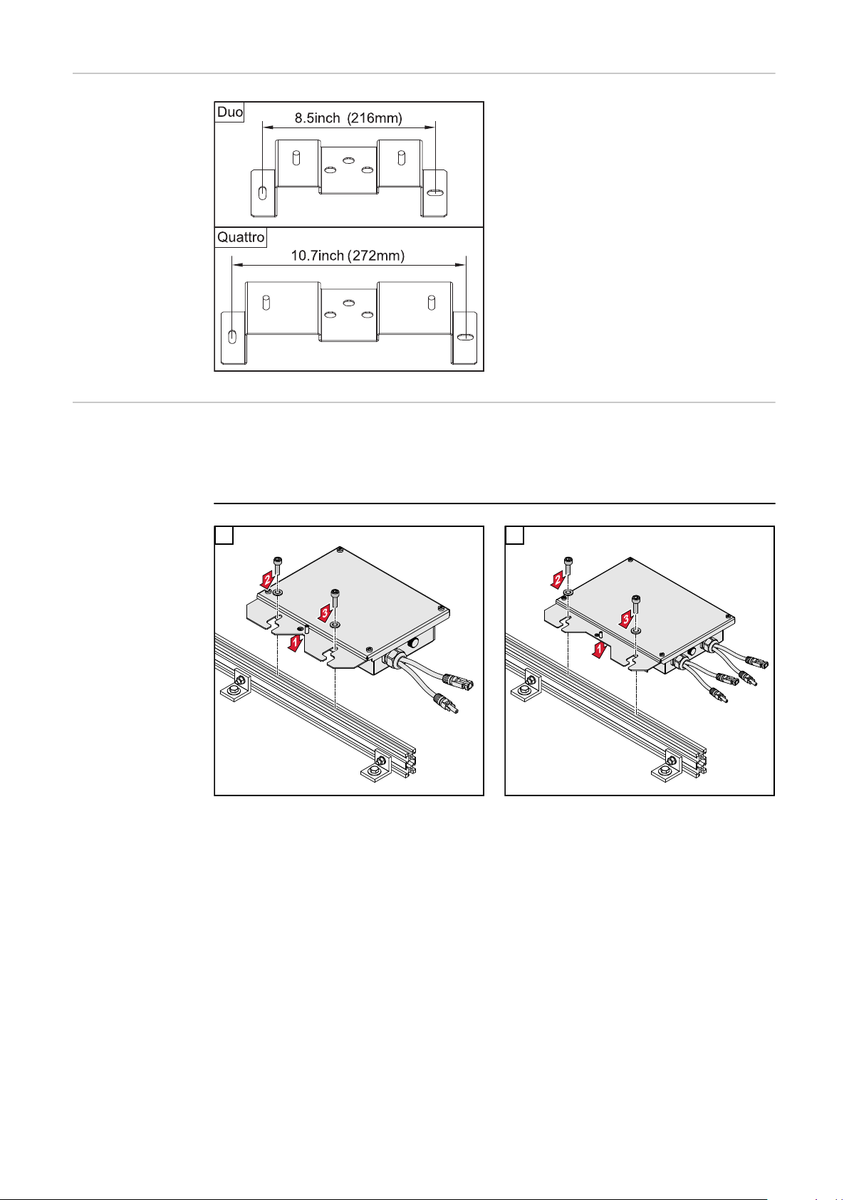
Drilling pattern Nameplate and warning labels should
be accessible after mounting.
Mounting the
Rapid Shutdown
Box - Duo on a
rail
IMPORTANT!
When mounting the Rapid Shutdown Box on a rail it is recommended to fix the
rail in an elevated position for increased installation comfort.
1
Rapid Shutdown Box - Duo
2
Rapid Shutdown Box - Quattro
12
Page 13

Attaching the
Rapid Shutdown
Box to the wall
1 2
EN-US
3
5
4
Fasteners not included
13
Page 14
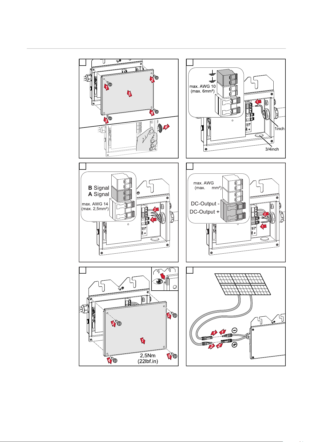
Connecting the Rapid Shutdown Box
8
10
Wiring of the
Rapid Shutdown
Box - Duo
1 2
3
4
5 6
14
Page 15

Connecting the
wires Rapid
Shutdown Box Quattro
IMPORTANT! Using 2 strings at least one string must be connected to input 1
because the Rapid Shutdown Box gets the supply from this input.
1 2
3 4
EN-US
5 6
15
Page 16

7
If other connectors than MC4 (Stäubli)
shall be used in conjunction with the
Fronius Rapid Shutdown Box it is recommended to cut the preconfigured
MC4 connectors and to be replaced by
preferred connector brand using proper tools and methods. Removal of the
whole cable set is not recommended
and will void warranty.
Connecting a
MC4-Y-Connector
Connecting several Rapid Shutdown Boxes
If multiple strings are connected to an MPP tracker, the string voltages should be
as equal as possible in order to avoid power losses.
1 2
16
Page 17

Connecting the
A1 A2
DC-Output
Duo / Quattro
Quattro
Signal Port
Duo / Quattro
Duo
wires to the Terminals
EN-US
Connecting the
Rapid Shutdown
Box to a SnapINverter
If the AC supply is interrupted, the inverter disconnects the PV DC supply via
the Rapid Shutdown Box. As soon as the AC supply is reinstated, the DC supply
will resume.
The system status of the Rapid Shutdown Box is displayed on the AC breaker
(e.g.: emergency stop). “OFF” means, that the AC supply is interrupted and the
Rapid Shutdown Box is in a safe state. When the AC breaker is set to “ON”, the
Rapid Shutdown Box is running and the AC supply is upright.
The signal relay in the Fronius inverter opens if the inverter loses the AC connection. The Rapid Shutdown Box interrupts the DC connection. However, the signal
relay can no longer be used for other functions (energy manager, alarm, etc.) if
the rapid shutdown initiation is to be triggered by an AC failure on the inverter.
17
Page 18

The inverter does not need to be configured after connecting the Rapid Shut-
3
2
1
Signal A
Signal B
put sticker on inverter
PHOTOVOLTAIC
RAPID SHUTDOWN
SYSTEM
EQUIPMENT
down Box. If settings have already been made regarding energy management,
check this section in the inverter Operating Instructions. The energy manager
(relay mode) must be set to 'ON' (factory setting).
Connecting the
Rapid Shutdown
Box to GEN24
Inverter
18
If the AC supply is interrupted, the inverter disconnects the PV DC supply via
the Rapid Shutdown Box. As soon as the AC supply is reinstated, the DC supply
will resume.
The signal relay in the Fronius inverter opens if the inverter loses the AC connection. The Rapid Shutdown Box interrupts the DC connection. However, the signal
relay can no longer be used for other functions (energy manager, alarm, etc.) if
the rapid shutdown initiation is to be triggered by an AC failure on the inverter.
The inverter does not need to be configured after connecting the Rapid Shutdown Box. If settings have already been made regarding energy management,
check this section in the inverter Operating Instructions. The energy manager
(relay mode) must be set to 'ON' (factory setting).
Page 19

Signal ASignal B
optional
put sticker on inverter
PHOTOVOLTAIC
RAPID SHUTDOWN
SYSTEM
EQUIPMENT
EN-US
Connecting the
Rapid Shutdown
Box Grounding
The hexagon nut and the spring washer required for connecting the grounding on
the threaded post are included in the scope of supply. The threaded post is electrically bonded to the Rapid Shutdown Box.
1
Equipment grounding of RSB - Duo
2
Equipment grounding of RSB - Quattro
19
Page 20

Optional: Connecting the Grounding to a Ground Lug - Variant 1
1 2
Optional: Connecting the Grounding to a Ground Lug - Variant 2
1 2
SnapINverter:
Connecting the
Rapid Shutdown
Box to an emergency stop button
Connecting to an external emergency stop button:
If an external emergency stop is required, it can be installed anywhere in the signal line. When the connected emergency stop button is pressed, the Rapid Shutdown is started and the PV field is disconnected from the inverter. As soon as the
emergency stop button is returned to its original position, the PV field is reconnected.
Requirements for the external emergency stop button:
Maximum switching load: 30 V DC / 5 mA
-
Nominal voltage between contacts and housing: 600 V DC
-
20
Page 21

GEN24 inverter:
Emergency Switch Stop
RSB Quattro
Connecting the
Rapid Shutdown
Box to an emergency stop button
Connecting to external emergency
stop:
If an external emergency stop is required, it can be installed anywhere in
the signal line. When the connected
emergency stop button is pressed, the
Rapid Shutdown is started and the PV
field is disconnected in the Rapid
Shutdown box. As soon as the emergency stop button is returned to its
original position, the PV field is reconnected.
Requirements for external emergency
stop:
Maximum switching load: 30 V
-
DC / 5 mA
Nominal voltage between contacts
-
and housing: 600 V DC
EN-US
Connecting the
Rapid Shutdown
Box to a Fronius
Primo 10.0 /
11.4 / 12.5 / 15.0
IMPORTANT!
Wiring schemes show best practice examples assuming that more than two PV
strings connected in parallel require overcurrent protection (e.
g. fusing). Refer to Primo installation manual regarding multi conductor wiring
and fusing details
If multiple strings are connected to an MPP tracker, the string voltages should be
as equal as possible in order to avoid power losses.
Connecting 4 Solar Module Strings to the Fronius Primo 10.0 / 11.4 / 12.5 / 15.0
21
Page 22

Connecting 5 Solar Module Strings to the Fronius Primo 10.0 / 11.4 / 12.5 / 15.0
RSB Quattro
RSB Quattro
RSB Duo
RSB Quattro
RSB Quattro
Connecting 6 Solar Module Strings to the Fronius Primo 10.0 / 11.4 / 12.5 / 15.0
Connecting the
Rapid Shutdown
Box to a Fronius
Primo GEN24
208-240
22
IMPORTANT!
Wiring schemes show best practice examples assuming that more than two PV
strings connected in parallel require overcurrent protection (e.
g., fusing). Refer to Primo installation manual regarding multi conductor wiring
and fusing details
Page 23

If several strings are connected to an MPP tracker, the string voltages should be
as equal as possible to avoid power losses.
Connection of 4 solar module strings to the Fronius Primo GEN24 208-240
EN-US
Connection of 5 solar module strings to the Fronius Primo GEN24 208-240
23
Page 24

24
Page 25

Sommaire
Généralités 26
PHOTOVOLTAIK (PV) SYSTEM EQUIPPED WITH RAPID SHUTDOWN 26
Sécurité 26
Conformité FCC / RSS 27
Concept d'appareil 28
Limites du système 28
Distance maximale entre la Rapid Shutdown Box et le panneau photovoltaïque. 29
Caractéristiques techniques 29
Compatibilité avec les onduleurs 30
Code d'état 307 sur la série d'onduleurs SnapINverter 31
Code de service 1175 sur la série d'onduleurs GEN24 31
Déclencher un Rapid Shutdown 32
Réinitialisation après un Rapid Shutdown 32
Auto-test 32
Montage de la Rapid Shutdown Box 33
Schéma de perçage 34
Monter la Rapid Shutdown Box – Duo sur un rail 34
Montage de la Rapid Shutdown Box sur le mur 35
Raccorder la Rapid Shutdown Box 36
Câbler la Rapid Shutdown Box – Duo 36
Raccorder des fils à la Rapid Shutdown Box - Quattro 37
Raccorder un connecteur MC4-Y 38
Connexion de plusieurs Rapid Shutdown box 38
Indications concernant le branchement des fils aux bornes de raccordement 39
Connecter la Rapid Shutdown Box à un SnapINverter 39
Raccordement de la Rapid Shutdown Box à un onduleur GEN24 40
Connecter la Rapid Shutdown Box à la terre 41
SnapINverter : Raccordement de la Rapid Shutdown Box à un bouton d'arrêt d'urgence 42
Onduleur GEN24 : Raccordement de la Rapid Shutdown Box à un bouton d'arrêt d'urgence
Connecter la Rapid Shutdown Box à un Fronius Primo 10.0/11.4/12.5/15.0 43
Raccordement de la Rapid Shutdown Box à un Fronius Primo GEN24 208-240 45
FR
43
25
Page 26

Généralités
PHOTOVOLTAIK
(PV) SYSTEM
EQUIPPED
WITH RAPID
SHUTDOWN
Sécurité
Conformément à la norme CSA C22.2 No.330-17, ce produit a été développé
comme une partie d'une « PHOTOVOLTAIK (PV) SYSTEM EQUIPPED WITH
RAPID SHUTDOWN ».
AVERTISSEMENT!
Les erreurs de manipulation et les erreurs en cours d'opération peuvent entraîner des dommages corporels et matériels graves.
La mise en service de votre Rapid Shutdown Box (RSB) ne peut être effectuée
que par du personnel formé à cet effet et dans le cadre des directives techniques. Avant la mise en service et l'exécution de travaux d'entretien, lire les consignes de sécurité.
AVERTISSEMENT!
Les erreurs en cours d'opération peuvent entraîner des dommages corporels et
matériels graves.
Seuls les installateurs électriciens agréés sont habilités à effectuer l'installation
et le raccordement de la Rapid Shutdown Box !
Respecter les consignes de sécurité !
Avant toute opération d'installation et de raccordement, veiller à ce que le côté
AC en amont de l'onduleur et le côté DC en amont de la Rapid Shutdown Box
soient hors tension.
AVERTISSEMENT!
Une décharge électrique peut être mortelle.
Des composants électriques insuffisamment dimensionnés peuvent causer de
graves dommages aux personnes et aux biens.
Tous les raccordements électriques doivent être réalisés conformément aux
▶
prescriptions du National Electrical Code ANSI/NFPA 70 et aux directives en
vigueur sur le site de l'installation.
Les installations au Canada doivent être réalisées conformément aux normes
▶
canadiennes en vigueur.
Utiliser uniquement des fils en cuivre pour toutes les bornes à ressort.
▶
Pour tous les câbles de mise à la terre et les fils de mise à la terre DC, utiliser
▶
une classe thermique appropriée, min. 90 °C (194 °F).
Voir le tableau 250.122 du NEC pour le dimensionnement correct des fils de
▶
mise à la terre
Une chute de tension et d'autres considérations peuvent exiger des sections
▶
de câble supérieures.
26
Page 27

AVERTISSEMENT!
(1)
(1)
Une connexion à la terre insuffisante peut entraîner de graves dommages corporels et matériels.
Les vis du boîtier constituent une connexion de terre appropriée pour la mise à la
terre du corps de l'appareil. Il ne faut en aucun cas remplacer ces vis par d'autres
vis qui n'offriraient pas ce type de connexion de terre autorisée !
ATTENTION!
Afin d'éviter d'endommager la Rapid Shutdown Box, respecter les points
suivants :
Les spécifications techniques doivent être observées.
▶
La membrane de compensation de pression (1) ne doit en aucun cas être util-
▶
isée en tant qu'arrivée de câble.
FR
Rapid Shutdown Box - Duo
REMARQUE!
Les modules solaires recevant de la lumière fournissent du courant à la Rapid
Shutdown Box lorsqu'ils sont raccordés.
REMARQUE!
Lors du montage en extérieur, utiliser exclusivement des gaines et des raccords
de gaine étanches à l'eau.
Les gaines et raccords de gaine ne sont pas compris dans la livraison de la Rapid
Shutdown Box. Les raccords de gaine doivent toujours être montés avec un écrou
de sécurité. Veiller au montage correct et à l'étanchéité des raccords de gaine.
REMARQUE!
Lors du raccordement de câbles DC, respecter la polarité.
IMPORTANT!
Le dispositif de déclenchement (onduleur) de la Rapid Shutdown Box doit être
identifié afin de reconnaître facilement l'état de la Rapid Shutdown Box.
Lorsque la Rapid Shutdown Box perd sa connexion AC, l'onduleur se transforme
en dispositif de déclenchement et d'affichage.
Rapid Shutdown Box - Quattro
Conformité
FCC / RSS
FCC
Cet appareil correspond aux valeurs limites imposées par la partie 15 des dispositions FCC pour un appareil numérique de classe B. Ces valeurs limites ont pour
27
Page 28

but d'apporter une protection appropriée contre les perturbations nocives dans
les locaux d'habitation. Cet appareil produit et utilise de l'énergie à haute
fréquence et peut engendrer des perturbations dans les communications radio
s'il n'est pas utilisé en conformité avec les instructions. Il est toutefois impossible
de garantir l'absence totale de perturbations dans une installation donnée.
Si, en désactivant puis en réactivant l'appareil, il est constaté que celui-ci perturbe la réception des ondes radio ou TV, il est recommandé à l'utilisateur d'y
remédier en appliquant une ou plusieurs des mesures suivantes :
Réorienter l'antenne de réception ou la positionner autrement
-
Augmenter la distance entre l'appareil et le récepteur
-
Raccorder l'appareil à un autre circuit électrique, auquel le récepteur n'est
-
pas connecté
Contacter le revendeur ou un technicien radio/TV spécialisé pour obtenir de
-
l'aide
Industrie Canada RSS
Cet appareil est conforme aux normes Industrie Canada RSS exemptes de licence. Son utilisation est soumise aux conditions suivantes :
(1) L'appareil ne doit causer aucune perturbation nocive.
(2) L'appareil doit pouvoir surmonter toutes les influences parasites constatées, y
compris les influences parasites susceptibles de perturber le fonctionnement.
Concept d'appareil
Limites du
système
La Rapid Shutdown Box constitue une solution confortable et sûre permettant
de satisfaire aux exigences de l'article 690.12 de l'édition 2014 du National Electrical Code. L'appareil est directement alimenté par le champ photovoltaïque et
dépend de l'état de l'émetteur de signal. L'émetteur de signal peut être commandé via le relais dans les onduleurs de la série SnapINverter. L'utilisation de
relais DC sectionneurs de charge assure l'isolation galvanique du champ photovoltaïque en cas de Rapid Shutdown.
La Rapid Shutdown Box assure que l'énergie qui reste dans les condensateurs de
l'onduleur soit déchargée dans l'intervalle requis. Afin que la totalité du système
fonctionne correctement, les ports de signal de toutes les Rapid Shutdown Box
doivent être reliés de série (voir chapitre « Raccorder la Rapid Shutdown Box »).
Les versions Duo et Quattro de l'appareil, ainsi que les appareils de fin de série
RSB Single et RSB Duo peuvent être mélangés selon les besoins.
Un Rapid Shutdown peut être déclenché par une panne AC, lorsque les lignes de
signal sont raccordées à l'onduleur. Un bouton d'arrêt d'urgence ou autre peut
également être utilisé comme alternative ou en supplément afin d'interrompre
les lignes de signal.
Nombre maximal de Rapid Shutdown Box sur un onduleur : 5
-
Résistance de ligne maximale autorisée dans la boucle de signal : 300 W
-
Longueur de câble maximale autorisée pour la boucle de signal avec AWG
-
14/16/18 ou 20 : 3200 ft (1 000 m)
28
Page 29

Distance maximale entre la Rapid Shutdown Box
et le panneau
photovoltaïque.
FR
Caractéristiques
techniques
RSB Duo RSB Quattro
Tension max. 600 V DC
Tension de départ 80 V DC
Courant d'entrée max. 25 A 25 A/25 A
Alimentation DC (du panneau photovoltaïque)
Autoconsommation pendant le fonctionnement
Température de fonctionnement admissible
Humidité admissible 0 à 100 % (sans condensation)
Altitude max. 4 000 m (13 123 ft.)
Nombre max. de circuits contrôlés
(selon NEC)
Type de coffret NEMA 4X
Dimensions de l'appareil H x l x P 286 x 246,5 x
Dimensions de transport H x l x P 330 x 305 x
-40 °C à +65 °C (-40 °F à +149 °F)
1 2
66,6 mm
(11,26 x 9,7 x
2,62 in.)
150 mm
(13 x 12 x 5,9 in.)
2 W
351 x 293 x
66,6 mm
(13,82 x 11,54 x
2,62 in.)
350 x 300 x
155 mm
(13,78 x 11,81 x
6,1 in.)
Poids de transport 2,7 kg (5,95 lbs.) 3,7 kg (8,16 lbs.)
Normes et réglementations UL1741 ; LTR AE-004-2015 ; FCC15
Classe B
29
Page 30

Compatibilité
avec les onduleurs
Onduleur (série SnapINverter) Rapid Shutdown Box - Duo / Quat-
tro
Fronius Galvo 1.5-1 208-240
Fronius Galvo 2.0-1 208-240
Fronius Galvo 2.5-1 208-240
Fronius Galvo 3.1-1 208-240
Fronius Primo 3.8-1 208-240
Fronius Primo 5.0-1 208-240
Fronius Primo 6.0-1 208-240
Fronius Primo 7.6-1 208-240
Fronius Primo 8.2-1 208-240
Fronius Primo 10.0-1 208-240 *)
Fronius Primo 11.4-1 208-240 *)
Fronius Primo 12.5-1 208-240 *)
Fronius Primo 15.0-1 208-240 *)
Fronius Symo 10.0-3 208-240
Fronius Symo 12.0-3 208-240
Fronius Symo 15.0-3 208
Fronius Symo 10.0-3 480 **)
Fronius Symo 12.5-3 480 **)
Fronius Symo 15.0-3 480 **)
Fronius Symo 17.5-3 480 **)
Fronius Symo 20.0-3 480 **)
Fronius Symo 22.7-3 480 **)
30
Fronius Symo 24.0-3 480 **)
Onduleur (série GEN24) Rapid Shutdown Box - Duo / Quat-
tro
Fronius Primo GEN24 3.8 / 3.8 Plus
208-240
Page 31

Onduleur (série GEN24) Rapid Shutdown Box - Duo / Quat-
tro
Fronius Primo GEN24 5.0 / 5.0 Plus
208-240
Fronius Primo GEN24 6.0 / 6.0 Plus
208-240
*) déclenchement par une panne AC uniquement avec l'étage de puissance SW2
version 0.6.34.4 ou supérieure. Voir la section Raccordement de la Rapid Shutdown Box à Primo 10.0 - 15.0 pour les détails de l'installation
**) Tension DC maximale : 600 V
FR
Code d'état 307
sur la série d'onduleurs SnapINverter
Code de service
1175 sur la série
d'onduleurs
GEN24
Code d'état 307 sur la série d'onduleurs SnapINverter :
Description : l'onduleur détecte une tension DC trop faible à l'entrée pour le
mode d'injection dans le réseau. Lorsque ce code de service s'affiche sur une
longue durée malgré la présence d'un rayonnement solaire, les étapes suivantes
peuvent aider à trouver l'erreur :
Vérifier la position du sectionneur DC sur l'onduleur – il devrait être sur ON
-
Lire la tension DC sur l'écran ou la mesurer sur les terminaux de l'onduleur
-
Si la tension DC est de 0 V, cela signifie que la Rapid Shutdown Box n'est
-
pas alimentée par le champ photovoltaïque ou qu'il n'existe pas de connexion électrique entre la Rapid Shutdown Box et l'onduleur. Vérifier le
câblage DC et les entrées de la Rapid Shutdown Box ! Au moins une
chaîne doit être raccordée à l'entrée 1 de la Rapid Shutdown Box - Quattro.
Si la tension DC est d'environ 28 V, cela signifie que la Rapid Shutdown
-
Box est alimentée et qu'elle attend l'autorisation au niveau des ports de
signal. Vérifier le câblage ainsi que tous les commutateurs de la boucle
de signal !
Si le code de service s'affiche toujours malgré le rayonnement solaire, pren-
-
dre contact avec le monteur de l'installation !
Code de service 1175 sur la série d'onduleurs GEN24 :
Description : l'onduleur détecte une tension DC trop faible à l'entrée pour le
mode d'injection dans le réseau. Lorsque ce code de service s'affiche sur une
longue durée malgré la présence d'un rayonnement solaire, les étapes suivantes
peuvent aider à trouver l'erreur :
Vérifier la position du sectionneur DC sur l'onduleur – il devrait être sur ON
-
Lire la tension DC sur l'écran ou la mesurer sur les terminaux de l'onduleur
-
Si la tension DC est de 0 V, cela signifie que la Rapid Shutdown Box n'est
-
pas alimentée par le champ photovoltaïque ou qu'il n'existe pas de connexion électrique entre la Rapid Shutdown Box et l'onduleur. Vérifier le
câblage DC et les entrées de la Rapid Shutdown Box ! Au moins une
chaîne doit être raccordée à l'entrée 1 de la Rapid Shutdown Box - Quattro.
Si la tension DC est d'environ 28 V, cela signifie que la Rapid Shutdown
-
Box est alimentée et qu'elle attend l'autorisation au niveau des ports de
signal. Vérifier le câblage ainsi que tous les commutateurs de la boucle
de signal !
Si le code de service s'affiche toujours malgré le rayonnement solaire, pren-
-
dre contact avec le monteur de l'installation !
31
Page 32

Déclencher un
Rapid Shutdown
En fonction de la configuration et de l'installation sur site, il existe deux façons
de déclencher un Rapid Shutdown :
Par perte de la connexion AC (uniquement pour la série d'onduleurs SnapIN-
-
verter) : lorsque la boucle de signal de l'onduleur est raccordée (voir chapitre
Raccordement de la Rapid Shutdown Box à un onduleur GEN24 page 40),
un Rapid Shutdown peut se produire en raison de l'interruption de la connexion AC. L'onduleur reconnaît une panne de la connexion AC et interrompt la
liaison avec les modules solaires par le biais de la Rapid Shutdown Box. Les
câbles sont déchargés et isolés.
Par un commutateur externe : si la reconnaissance de pannes via la connex-
-
ion AC n'est pas adaptée ou si d'autres options sont nécessaires, des commutateurs externes peuvent être installés dans la boucle de signal (voir
chapitre SnapINverter : Raccordement de la Rapid Shutdown Box à un
bouton d'arrêt d'urgence page 42). Un Rapid Shutdown peut ensuite être
déclenché par pression sur l'un de ces commutateurs. Les câbles sont
déchargés et isolés.
Réinitialisation
après un Rapid
Shutdown
Auto-test L'auto-test de la fonction d'arrêt rapide (RSD) ne peut être réalisé que manuelle-
Pour remettre l'installation photovoltaïque en service après un Rapid Shutdown :
Si la ligne de signal vers l'onduleur est fermée, une connexion AC doit être
-
disponible afin de redémarrer l'installation photovoltaïque.
Ouvrir le commutateur utilisé pour déclencher le Rapid Shutdown.
-
Vérifier que tous les autres commutateurs externes de la boucle de signal
-
sont fermés.
ment. L'auto-test ne concerne que le circuit de décharge de la Rapid Shutdown
Box.
Séquence d'auto-test manuel :
un auto-test manuel peut être déclenché par une interruption de la connexion
AC (par ex. : disjoncteur AC).
La décharge de la Rapid Shutdown Box doit être mesurée et vérifiée à l'aide d'un
multimètre.
Le code d'erreur « AC_SystemFailure » s'affiche sur l'écran de l'onduleur.
32
Page 33

Montage de la Rapid Shutdown Box
NEMA
TYPE 4X
4000 m /
13100 ft.
0 m / 0 ft.
> 4000 m /
13100 ft.
NH
3
FR
Positions de montage possibles lors de l'utilisation en extérieur :
33
Page 34

Schéma de
perçage
Choisir la position de montage de la
Rapid Shutdown Box de manière à ce
que la plaque signalétique et l'autocollant de sécurité soient encore visibles
après le montage.
Monter la Rapid
Shutdown Box –
Duo sur un rail
IMPORTANT!
Lorsque vous montez la Rapid Shutdown Box sur un rail, il est recommandé de
fixer le rail en position élevée pour un meilleur confort d'installation.
1
Rapid Shutdown Box – Duo
2
Rapid Shutdown Box – Quattro
34
Page 35

Montage de la
Rapid Shutdown
Box sur le mur
1 2
FR
3
5
4
Matériel de fixation non inclus
35
Page 36

Raccorder la Rapid Shutdown Box
8
10
Câbler la Rapid
Shutdown Box –
Duo
1 2
3
4
5 6
36
Page 37

Raccorder des
fils à la Rapid
Shutdown Box Quattro
IMPORTANT ! En cas d'utilisation de 2 chaînes, au moins une des deux doit être
raccordée à l'entrée 1 car l'alimentation de la Rapid Shutdown Box a lieu par le
biais de cette entrée.
1 2
FR
3 4
5 6
37
Page 38

7
Si d'autres connecteurs que MC4
(Stäubli) doivent être utilisés en association avec la Fronius Rapid Shutdown Box, il est conseillé de couper les
connecteurs MC4 préconfigurés et de
les remplacer par la marque de connecteurs souhaitée en utilisant des
outils et méthodes adaptés. Retirer la
totalité du jeu de câbles n'est pas recommandé. Cela annulerait la garantie.
Raccorder un
connecteur
MC4-Y
Connexion de
plusieurs Rapid
Shutdown box
Si plusieurs chaînes sont connectées à un tracker MPP, les tensions des chaînes
doivent être aussi égales que possible afin d'éviter toute perte de puissance.
1 2
38
Page 39

Indications con-
A1 A2
DC-Output
Duo / Quattro
Quattro
Signal Port
Duo / Quattro
Duo
cernant le branchement des fils
aux bornes de
raccordement
FR
Connecter la
Rapid Shutdown
Box à un SnapINverter
Si l'alimentation AC est interrompue, l'onduleur déconnecte l'alimentation DC
photovoltaïque via la Rapid Shutdown Box. Dès que l'alimentation AC est
rétablie, l'alimentation DC l'est également.
L'état de la Rapid Shutdown Box est affiché sur le disjoncteur AC (par ex. : arrêt
d'urgence). « OFF » signifie que l'alimentation AC est interrompue et que la Rapid Shutdown Box est sécurisée. Lorsque le disjoncteur AC est réglé sur « ON », la
Rapid Shutdown Box fonctionne et l'alimentation AC est active.
Le relais de signalisation de l'onduleur Fronius s'ouvre si l'onduleur perd la connexion AC. La Rapid Shutdown Box interrompt la connexion DC. Toutefois, le re-
lais de signalisation ne peut plus être utilisé pour d'autres fonctions (gestion de
39
Page 40

l'énergie, alarme, etc.) si le dispositif d'arrêt rapide doit être déclenché par une
3
2
1
Signal A
Signal B
put sticker on inverter
PHOTOVOLTAIC
RAPID SHUTDOWN
SYSTEM
EQUIPMENT
panne d'alimentation AC sur l'onduleur.
L'onduleur n'a pas besoin d'être configuré après la connexion de la Rapid Shutdown Box. Si des réglages relatifs à la gestion de l'énergie ont déjà été effectués,
consulter la section correspondante dans les Instructions de service de l'onduleur. L'appareil de gestion de l'énergie (mode relais) doit être réglé sur « ON »
(réglage usine).
Raccordement
de la Rapid Shutdown Box à un
onduleur GEN24
40
Lors d'une coupure de courant côté AC, l'onduleur désactive le côté photovoltaïque DC via la Rapid Shutdown Box. Dès que la tension AC est de nouveau
disponible, le côté DC est réactivé.
Le relais de signal de l'onduleur Fronius s'ouvre lorsque l'onduleur perd la connexion AC. La Rapid Shutdown Box interrompt la connexion DC. Le relais de sig-
nal ne peut cependant plus être utilisé pour d'autres fonctions (gestionnaire
d'énergie, alarme,...) si le Rapid Shutdown doit être déclenché par une panne AC
sur l'onduleur.
L'onduleur ne doit pas être configuré après le raccordement de la Rapid Shutdown Box. Si des réglages ont déjà été effectués en matière de gestion de l'énergie, contrôler ce paramètre dans les Instructions de service de l'onduleur. Le gestionnaire de l'énergie (mode relais) doit être sur « ON » (réglage usine).
Page 41

Signal ASignal B
optional
put sticker on inverter
PHOTOVOLTAIC
RAPID SHUTDOWN
SYSTEM
EQUIPMENT
FR
Connecter la
Rapid Shutdown
Box à la terre
L'écrou hexagonal et la rondelle élastique nécessaires pour connecter la mise à la
terre sur la tige filetée sont compris dans la livraison. La tige filetée est connectée électriquement à la Rapid Shutdown Box.
1
Mise à la terre de la RSB – Duo
2
Mise à la terre de la RSB – Quattro
41
Page 42

En option : Connecter la mise à la terre à une borne de terre – Variante 1
1 2
En option : Connecter la mise à la terre à une borne de terre – Variante 2
1 2
SnapINverter :
Raccordement
de la Rapid Shutdown Box à un
bouton d'arrêt
d'urgence
Raccordement à un bouton d'arrêt d'urgence externe :
si un bouton d'arrêt d'urgence externe est nécessaire, il peut être installé n'importe où sur la ligne de signal. Lors de l'actionnement du bouton d'arrêt d'urgence raccordé, le Rapid Shutdown est déclenché et le champ photovoltaïque
est déconnecté de l'onduleur. Dès que le bouton d'arrêt d'urgence est replacé
dans sa position initiale, le champ photovoltaïque est réactivé.
Exigences concernant le bouton d'arrêt d'urgence externe :
Charge de commutation maximale : 30 V DC / 5 mA
-
Tension nominale entre les contacts et le boîtier : 600 V DC
-
42
Page 43

Onduleur
Emergency Switch Stop
RSB Quattro
GEN24 : Raccordement de la
Rapid Shutdown
Box à un bouton
d'arrêt d'urgence
Raccordement à un arrêt d'urgence
externe :
si un bouton d'arrêt d'urgence externe
est nécessaire, il peut être installé
n'importe où sur la ligne de signal. Lors
de l'actionnement du bouton d'arrêt
d'urgence raccordé, le Rapid Shutdown
est déclenché et le champ photovoltaïque est déconnecté dans la Rapid
Shutdown Box. Dès que le bouton
d'arrêt d'urgence est replacé dans sa
position initiale, le champ photovoltaïque est réactivé.
Exigences relatives à l'arrêt d'urgence
externe :
Charge de commutation maxim-
-
ale : 30 V DC / 5 mA
Tension nominale entre les con-
-
tacts et le boîtier : 600 V DC
FR
Connecter la
Rapid Shutdown
Box à un Fronius
Primo
10.0/11.4/12.5/1
5.0
IMPORTANT!
Les plans de câblage constituent les meilleurs exemples pratiques dans le cas
où plus de deux chaînes photovoltaïques connectées en parallèle nécessitent
une protection de surintensité (par ex.
fusibles). Se référer aux Instructions d'installation du Primo pour le câblage
multi-conducteur et les détails des fusibles.
Si plusieurs chaînes sont connectées à un tracker MPP, les tensions des chaînes
doivent être aussi égales que possible afin d'éviter toute perte de puissance.
Connecter 4 chaînes de modules solaires au Fronius Primo 10.0/11.4/12.5/15.0
43
Page 44

RSB Quattro
RSB Quattro
RSB Duo
RSB Quattro
RSB Quattro
Connecter 5 chaînes de modules solaires au Fronius Primo 10.0/11.4/12.5/15.0
Connecter 6 chaînes de modules solaires au Fronius Primo 10.0/11.4/12.5/15.0
44
Page 45

Raccordement
de la Rapid Shutdown Box à un
Fronius Primo
GEN24 208-240
Raccordement de 4 chaînes de modules solaires au Fronius Primo GEN24 208-240
IMPORTANT!
Les schémas de câblage montrent les exemples de bonne pratique en supposant
que plus de deux chaînes photovoltaïques connectées en parallèle nécessitent
une protection contre les surintensités (par ex.
fusible). Voir le manuel d'installation Primo en ce qui concerne les détails d'installation de fusibles et de câblages à multiconducteurs
Si plusieurs chaînes sont connectées à un tracker MPP, les tensions de chaîne
doivent être aussi élevées que possible pour éviter les pertes de puissance.
FR
45
Page 46

Raccordement de 5 chaînes de modules solaires au Fronius Primo GEN24 208-240
46
Page 47

Contenido
General 48
PHOTOVOLTAIK (PV) SYSTEM EQUIPPED WITH RAPID SHUTDOWN 48
Seguridad 48
Conformidad con FCC / RSS 49
Concepto del sistema 50
Limitaciones del sistema 50
Distancia máxima entre la Caja de cierre rápido y el conjunto fotovoltaico 51
Datos técnicos 51
Compatibilidad con inversores 52
Código de servicio 307 en la serie SnapINverter 53
Código de servicio 1175 en la serie de inversores GEN24 53
Activación del cierre rápido 54
Realizar un restablecimiento después de un cierre rápido 54
Autocomprobación 54
Instalación de la Caja de cierre rápido 55
Patrón de taladrado 56
Montaje de la Caja de cierre rápido - Duo en un riel 56
Fijar la Caja de cierre rápido a la pared 57
Conexión de la Caja de cierre rápido 58
Cableado de la Caja de cierre rápido - Duo 58
Conexión de los cables de la Caja de cierre rápido - Quattro 59
Instalación del conector MC4-Y 60
Conexión de varias Cajas de cierre rápido 60
Conexión de los cables a los bornes 61
Conexión de la Rapid Shutdown Box a un SnapINverter 61
Conexión de la Rapid Shutdown Box al inversor GEN24 62
Conexión de puesta a tierra de la Caja de cierre rápido 63
SnapINverter: Conexión de la Rapid Shutdown Box a un botón de parada de emergencia 64
Inversor GEN24: Conexión de la Rapid Shutdown Box a un botón de parada de emergencia
Conexión de la Caja de cierre rápido a Fronius Primo 10.0 / 11.4 / 12.5 / 15.0 65
Conexión de la Rapid Shutdown Box a un Fronius Primo GEN24 208-240 67
ES-MX
65
47
Page 48

General
PHOTOVOLTAIK
(PV) SYSTEM
EQUIPPED
WITH RAPID
SHUTDOWN
Seguridad
De acuerdo con el estándar CSA C22.2 No.330-17, este producto se desarrolló
como parte de una “PHOTOVOLTAIK (PV) SYSTEM EQUIPPED WITH RAPID
SHUTDOWN”.
¡PELIGRO!
Los fallos del sistema y el trabajo realizado de manera incorrecta pueden causar
lesiones graves y daños en la propiedad.
Solo personal cualificado tiene autorización para poner en servicio la Rapid Shutdown Box (RSB) y solo dentro del alcance de las respectivas normas técnicas. No
haga la puesta en servicio ni trabajos de mantenimiento hasta que haya leído las
normas de seguridad.
¡PELIGRO!
El trabajo realizado de manera incorrecta puede causar heridas graves y daños.
La Rapid Shutdown Box solo debe ser instalada y conectada por electricistas certificados.
¡Siga las normas de seguridad!
Antes de llevar a cabo una instalación o conexión, desconecte el suministro
eléctrico de CA al inversor y el suministro eléctrico de CC a la Rapid Shutdown
Box.
¡PELIGRO!
Una descarga eléctrica puede ser fatal.
Los componentes eléctricos con tamaños inadecuados pueden ocasionar lesiones graves y daños a la propiedad.
Todas las conexiones eléctricas se deben realizar en conformidad con el
▶
Código Eléctrico Nacional, ANSI/NFPA 70 y demás regulaciones aplicables
al lugar de instalación.
Las instalaciones llevadas a cabo en Canadá deben cumplir con las normas
▶
canadienses correspondientes.
Utilice únicamente cables de cobre para todos los bornes de conexión de
▶
tipo resorte.
Para todos los cables de masa y cables de masa de CC, use una clase térmica
▶
adecuada, mín. 194 °F (90 °C).
Consulte la tabla NEC 250.122 para conocer las dimensiones correctas de
▶
los cables de masa.
La pérdida de tensión y otras consideraciones pueden significar que se deban
▶
utilizar diámetros más grandes de cable.
48
Page 49

¡PELIGRO!
(1)
(1)
Una conexión de conductor protector inadecuada puede causar lesiones graves
y daño a la propiedad.
Los tornillos de la carcasa proporcionan una conexión de conductor protector
adecuada para poner a tierra la carcasa y no deben ser reemplazados, bajo ninguna circunstancia, por ningún otro tornillo que no proporcione una conexión de
conductor protector confiable.
¡PRECAUCIÓN!
Se deben observar los siguientes puntos para evitar que la Rapid Shutdown Box
se dañe:
Se deben seguir las especificaciones técnicas.
▶
Nunca se debe utilizar la membrana de compensación de presión (1) para el
▶
cableado.
Rapid Shutdown Box - Duo
¡OBSERVACIÓN!
Los módulos solares expuestos a la luz suministran corriente a la Rapid Shutdown Box si están conectados.
Rapid Shutdown Box - Quattro
ES-MX
Conformidad
con FCC / RSS
¡OBSERVACIÓN!
Cuando instale en el exterior, use solamente accesorios y conductos impermeables.
Los tubos y conexiones no se suministran con la Rapid Shutdown Box. Las conexiones siempre se deben instalar con una tuerca autoblocante. Asegúrese de que
las conexiones se instalen y sellen correctamente.
¡OBSERVACIÓN!
Al conectar cables de CC, asegúrese de que la polaridad sea correcta.
¡IMPORTANTE!
El equipo detonante (inversor) de la Rapid Shutdown Box debe ser marcado para
identificar claramente el estado de la Rapid Shutdown Box.
Si la Rapid Shutdown Box pierde el acoplamiento a la red, el inversor se convierte
en el detonante y en la pantalla.
FCC
Este dispositivo corresponde a los valores límites para un dispositivo digital de
49
Page 50

clase B, de conformidad con la Parte 15 de las normas FCC. Los valores límites
deben proporcionar una protección adecuada contra interferencias perjudiciales
en las residencias. Este dispositivo crea y utiliza energía de alta frecuencia y
puede interferir en las radiocomunicaciones cuando no se utiliza según las instrucciones. Sin embargo, no se garantiza que no exista interferencia en una determinada instalación.
Si este dispositivo interfiere con la recepción de radio o televisión al encenderlo o
apagarlo, se recomienda que el usuario resuelva el problema con una o más de
las siguientes medidas:
Ajustar o reponer la antena de recepción.
-
Aumentar la distancia entre el dispositivo y el receptor.
-
Conectar el dispositivo a otro circuito, que no incluya el receptor.
-
Para obtener mayor asistencia, comuníquese con el vendedor minorista o un
-
técnico de radio/TV con experiencia.
Industry Canada RSS
El dispositivo corresponde a los estándares de Industry Canada RSS sin licencia.
El funcionamiento depende de las siguientes condiciones:
(1) El dispositivo no debe causar interferencia perjudicial.
(2) El dispositivo debe aceptar cualquier interferencia recibida, incluida interferencia que pueda causar una operación indeseada.
Concepto del
sistema
Limitaciones del
sistema
La Rapid Shutdown Box brinda una manera práctica y segura de cumplir con el
Artículo 690.12 de la edición 2014 del Código Eléctrico Nacional. El dispositivo
se alimenta directamente de un conjunto fotovoltaico y es controlado en función
del estado del puerto de señal. El puerto de señal se puede controlar mediante
un borne relé en la serie SnapINverter. El uso de un relé CC, que también funciona como interruptor-seccionador, garantiza que el conjunto fotovoltaico esté
aislado galvánicamente en el caso de un cierre rápido.
La Rapid Shutdown Box garantiza que la energía residual en los condensadores
del inversor se descargue en el período requerido. Para garantizar que todo el sistema funcione correctamente, los puertos de señal de todas las Rapid Shutdown
Boxes se deben conectar en serie (consulte la sección "Conexión de la Rapid
Shutdown Box"). Para ello, se pueden combinar aleatoriamente las variantes Duo
y Quattro del dispositivo y también las versiones descontinuadas RSB Single y
RSB Multi.
La Rapid Shutdown Box se puede inicializar mediante una falla de CA, si los
cables de señal están conectados al inversor. Además, se puede utilizar un botón
de parada de emergencia que interrumpe los cables de señal.
Cantidad máxima de Cajas de cierre rápido por inversor: 5
-
Máxima resistencia de cable permitida por ciclo de señal: 300 W
-
Máxima longitud de cable permitida para ciclo de señal utilizando AWG 14,
-
16, 18 o 20: 3200 ft (1000 m)
50
Page 51

Distancia
máxima entre la
Caja de cierre
rápido y el conjunto fotovoltaico
ES-MX
Datos técnicos
RSB Duo RSB Quattro
Voltaje máximo 600 VCC
Tensión inicial 80 VCC
Máxima corriente de entrada 25 A 25 A / 25 A
Alimentación principal CC (del conjunto fotovoltaico)
Autoconsumo durante el funcionamiento
Temperatura operativa permitida -40 °F a +149 °F (-40 °C a +65 °C)
Humedad permitida 0 - 100 % (sin condensación)
Altitud máxima 13,123 ft (4000 m)
Cantidad máx. de circuitos eléctricos
controlados (según NEC)
Tipo de gabinete NEMA 4X
Dimensiones del dispositivo a x a x p 11.26 x 9.7 x 2.62
(286 x 246,5 x
Dimensiones de envío a x a x p 13 x 12 x 5.9 in.
(330x305x150
1 2
in.
66,6 mm)
mm)
2 W
13.82x11.54x2.62
in.
(351 x 293 x 66,6
mm)
13.78x11.81x6.1in
.
(350x300x155
mm)
Peso de envío 5.95 lbs. (2,7 kg) 8.16 lbs. (3,7 kg)
Normas y regulaciones UL1741; LTR AE-004-2015; FCC15
Clase B
51
Page 52

Compatibilidad
con inversores
Inversor (serie SnapINverter) Rapid Shutdown Box - Duo / Quat-
tro
Fronius Galvo 1.5-1 208-240
Fronius Galvo 2.0-1 208-240
Fronius Galvo 2.5-1 208-240
Fronius Galvo 3.1-1 208-240
Fronius Primo 3.8-1 208-240
Fronius Primo 5.0-1 208-240
Fronius Primo 6.0-1 208-240
Fronius Primo 7.6-1 208-240
Fronius Primo 8.2-1 208-240
Fronius Primo 10.0-1 208-240 *)
Fronius Primo 11.4-1 208-240 *)
Fronius Primo 12.5-1 208-240 *)
Fronius Primo 15.0-1 208-240 *)
Fronius Symo 10.0-3 208-240
Fronius Symo 12.0-3 208-240
Fronius Symo 15.0-3 208
Fronius Symo 10.0-3 480 **)
Fronius Symo 12.5-3 480 **)
Fronius Symo 15.0-3 480 **)
Fronius Symo 17.5-3 480 **)
Fronius Symo 20.0-3 480 **)
Fronius Symo 22.7-3 480 **)
52
Fronius Symo 24.0-3 480 **)
Inversor (serie GEN24) Rapid Shutdown Box - Duo / Quat-
tro
Fronius Primo GEN24 3.8 / 3.8 Plus
208-240
Page 53

Inversor (serie GEN24) Rapid Shutdown Box - Duo / Quat-
tro
Fronius Primo GEN24 5.0 / 5.0 Plus
208-240
Fronius Primo GEN24 6.0 / 6.0 Plus
208-240
*) Iniciación a través de pérdida de CA solo con etapa de potencia SW2 versión
0.6.34.4 o superior. Consulte la sección Conectar la Rapid Shutdown Box al
Primo 10.0 - 15.0 para obtener información sobre la instalación
**) tensión continua máxima: 600 V
ES-MX
Código de servicio 307 en la
serie SnapINverter
Código de servicio 1175 en la
serie de inversores GEN24
Código de servicio 307 en la pantalla de la serie SnapINverter:
Descripción: En la entrada, el inversor identifica la tensión continua demasiado
baja para el suministro de energía a la red. Si el código de servicio aparece por un
período de tiempo pese a la radiación solar, los siguientes pasos pueden ayudarlo
a descubrir el error:
Verificar la posición del seccionador CC en el inversor, debe estar encendido.
-
Leer la tensión continua en la pantalla o medirla en los bornes del inversor.
-
Si la tensión continua es 0 V, significa que la Rapid Shutdown Box no
-
recibe alimentación del conjunto fotovoltaico o no hay una conexión
eléctrica entre la Rapid Shutdown Box y el inversor. Verificar el cableado
de CC, incluidas las entradas de la Rapid Shutdown Box. Rapid Shut-
down Box - Quattro: Al menos una serie fotovoltaica debe estar conectada a la entrada 1.
Si la tensión continua es de aproximadamente 28 V, significa que la Rapid
-
Shutdown Box recibe alimentación eléctrica y está esperando la
aprobación en los puertos de señal. Verificar el cableado del ciclo de
señal y la posición de los interruptores en el ciclo de señal.
Si el código de servicio aún aparece pese a la radiación solar, comuníquese
-
con su ingeniero en sistemas.
Código de servicio 1175 en la serie de inversores GEN24:
Descripción: El inversor detecta tensión continua insuficiente en la entrada para
la operación de alimentación de energía de la red. Si este código de servicio
ocurre durante un período de tiempo más largo pese a la presencia de radiación
solar, los siguientes pasos pueden ayudarlo a encontrar el error:
Verificar la posición del seccionador CC en el inversor. Debe estar encendido.
-
Leer la tensión continua en la pantalla o medirla en los bornes del inversor.
-
Si la tensión continua es 0 V, significa que la Rapid Shutdown Box no
-
recibe alimentación del conjunto fotovoltaico o que no hay una conexión
eléctrica entre la Rapid Shutdown Box y el inversor. Verifique el cableado
de CC, incluidas las entradas de la Rapid Shutdown Box. Con la Rapid
Shutdown Box - Quattro, al menos se debe conectar una serie fotovoltaica a la entrada 1.
Si la tensión continua es de aproximadamente 28 V, significa que la Rapid
-
Shutdown Box está siendo suministrada y está esperando la liberación en
los puertos de señal. Verifique el cableado del ciclo de señal y la posición
de todos los interruptores en el ciclo de señal.
Si el código de servicio sigue presente a pesar de la radiación solar,
-
comuníquese con el instalador de su sistema.
53
Page 54

Activación del
cierre rápido
Se pueden desencadenar dos tipos distintos de cierre rápido dependiendo de la
configuración e instalación en el lugar:
Mediante la pérdida de acoplamiento a la red (solo para la serie de inversores
-
SnapINverter): Si el ciclo de señal ha sido conectado al inversor (consulte el
capítulo Conexión de la Rapid Shutdown Box al inversor GEN24 en la página
62), puede ocurrir un cierre rápido al interrumpir el acoplamiento a la red.
El inversor detecta una falla del acoplamiento a la red y apaga la conexión
con los módulos solares a través de la Rapid Shutdown Box. Las líneas se
descargan y se aíslan.
Mediante interruptor externo: Si la detección de una falla a través del aco-
-
plamiento a la red no es adecuada o se requieren opciones adicionales, se
pueden instalar interruptores externos en el ciclo de señal (consulte el
capítulo SnapINverter: Conexión de la Rapid Shutdown Box a un botón de
parada de emergencia en la página 64). Después, el cierre rápido puede ac-
tivarse al presionar uno de estos interruptores. Las líneas se descargan y se
aíslan.
Realizar un
restablecimiento
después de un
cierre rápido
Autocomprobación
Para reiniciar la instalación fotovoltaica después de un cierre rápido:
Si la línea de señal para el inversor está cerrada, debe haber un acoplamiento
-
a la red presente para reiniciar la instalación fotovoltaica.
Abra el interruptor que se usó para desencadenar el cierre rápido.
-
Revise el resto de los interruptores externos en el ciclo de señal para com-
-
probar si están cerrados.
La autocomprobación de la función de cierre rápido (RSD) solo se puede realizar
manualmente. La autocomprobación solo afecta al circuito de descarga de la
Rapid Shutdown Box.
Secuencia de autocomprobación manual:
una autocomprobación manual puede activarse por una interrupción del acoplamiento a la red (por ejemplo: interruptor de CA).
Se debe medir y comprobar la descarga de la Rapid Shutdown Box con un
multímetro.
El código de error “AC_SystemFailure” se muestra en la pantalla del inversor.
54
Page 55

Instalación de la Caja de cierre rápido
NEMA
TYPE 4X
4000 m /
13100 ft.
0 m / 0 ft.
> 4000 m /
13100 ft.
NH
3
ES-MX
Posibles posiciones de montaje para uso a la intemperie:
55
Page 56

Patrón de taladrado
Las etiquetas de advertencia e identificación deben ser de fácil acceso
después del montaje.
Montaje de la
Caja de cierre
rápido - Duo en
un riel
¡IMPORTANTE!
Al montar la Caja de cierre rápido en un riel, se recomienda fijar el riel en una
posición elevada para facilitar la instalación.
1
Caja de cierre rápido - Duo
2
Caja de cierre rápido - Quattro
56
Page 57

Fijar la Caja de
cierre rápido a la
pared
1 2
ES-MX
3
5
4
No se incluyen los sujetadores.
57
Page 58

Conexión de la Caja de cierre rápido
8
10
Cableado de la
Caja de cierre
rápido - Duo
1 2
3
4
5 6
58
Page 59

Conexión de los
cables de la Caja
de cierre rápido Quattro
¡IMPORTANTE! Al utilizar 2 series fotovoltaicas, al menos una de ellas debe estar conectada a la entrada 1, ya que la Caja de cierre rápido recibe la alimentación eléctrica por esta entrada.
1 2
ES-MX
3 4
5 6
59
Page 60

7
Si se deben utilizar otros conectores
aparte de MC4 (Stäubli) junto con la
Caja de cierre rápido Fronius, se recomienda cortar los conectores MC4
preconfigurados y reemplazarlos por la
marca de conectores preferida utilizando las herramientas y los métodos
adecuados. No se recomienda retirar
todo el conjunto del cable; esta acción
anulará la garantía.
Instalación del
conector MC4-Y
Conexión de
varias Cajas de
cierre rápido
Si varias series fotovoltaicas están conectadas a un rastreador MPP, las tensiones
de estas series deben ser lo más similares posible para evitar pérdidas de energía.
1 2
60
Page 61

Conexión de los
A1 A2
DC-Output
Duo / Quattro
Quattro
Signal Port
Duo / Quattro
Duo
cables a los
bornes
ES-MX
Conexión de la
Rapid Shutdown
Box a un SnapINverter
Si se interrumpe el suministro de CA, el inversor desconecta el suministro de CC
del conjunto fotovoltaico mediante la Rapid Shutdown Box. Tan pronto como se
restablezca el suministro de CA, se reiniciará el suministro de CC.
El estado del sistema de Rapid Shutdown Box se muestra en el interruptor de CA
(por ejemplo: parada de emergencia). “APAGADO” significa que el suministro de
CA está interrumpido y la Rapid Shutdown Box está en un estado seguro.
Cuando el interruptor de CA está en “ENCENDIDO”, la Rapid Shutdown Box
está funcionando y el suministro de CA está en posición vertical.
El relé de señal en el inversor Fronius se abre si el inversor pierde el acoplamiento a la red. La Rapid Shutdown Box interrumpe el acoplamiento de la red. Sin
embargo, el relé de señal ya no puede utilizarse para otras funciones (gestor de
61
Page 62

energía, alarma, etc.) si el inicio del cierre rápido es activado por una avería de
3
2
1
Signal A
Signal B
put sticker on inverter
PHOTOVOLTAIC
RAPID SHUTDOWN
SYSTEM
EQUIPMENT
CA en el inversor.
El inversor no necesita configurarse después de conectar la Caja de cierre rápido.
Si ya se ha hecho una configuración con relación a la gestión de energía, revise
esta sección en el manual de instrucciones del inversor. El gestor de energía
(modo relé) debe estar en “Encendido” (configuración de fábrica).
Conexión de la
Rapid Shutdown
Box al inversor
GEN24
62
Si se interrumpe el suministro de CA, el inversor desconecta el suministro de CC
del conjunto fotovoltaico mediante la Rapid Shutdown Box. Tan pronto como se
restablezca el suministro de CA, se reiniciará el suministro de CC.
El relé de señal en el inversor Fronius se abre si el inversor pierde el acoplamiento a la red. La Rapid Shutdown Box interrumpe la conexión de CC. Sin em-
bargo, el relé de señal ya no puede utilizarse para otras funciones (gestor de energía, alarma, etc.) si el inicio del cierre rápido es activado por una falla de CA en
el inversor.
El inversor no necesita configurarse después de conectar la Rapid Shutdown Box.
Si ya se ha hecho una configuración con relación a la gestión de energía, revise
esta sección en el manual de instrucciones del inversor. El gestor de energía
(modo relé) debe estar en “Encendido” (configuración de fábrica).
Page 63

Signal ASignal B
optional
put sticker on inverter
PHOTOVOLTAIC
RAPID SHUTDOWN
SYSTEM
EQUIPMENT
ES-MX
Conexión de
puesta a tierra
de la Caja de cierre rápido
La tuerca hexagonal y la arandela del resorte necesarias para realizar la puesta a
tierra en la conexión roscada se suministran con el dispositivo. La conexión roscada está unida eléctricamente a la Caja de cierre rápido.
1
Puesta a tierra del equipo RSB - Duo
2
Puesta a tierra del equipo RSB - Quattro
63
Page 64

Opcional: Conexión de la puesta a tierra al terminal de tierra - variante 1
1 2
Opcional: Conexión de la puesta a tierra al terminal de tierra - variante 2
1 2
SnapINverter:
Conexión de la
Rapid Shutdown
Box a un botón
de parada de
emergencia
Conexión a un botón de parada de emergencia externo:
Si se requiere una parada de emergencia, puede instalarse en cualquier lugar en
la línea de señal. Cuando se presiona el botón de parada de emergencia conectado, se inicia el cierre rápido y el conjunto fotovoltaico se desconecta del inversor. Cuando el botón de parada de emergencia regresa a su posición original,
se reconecta el conjunto fotovoltaico.
Requisitos para el botón de parada de emergencia externo:
Carga de conmutación máxima: 30 V CC / 5 mA
-
Tensión nominal entre contactos y carcasa: 600 V CC
-
64
Page 65

Inversor GEN24:
Emergency Switch Stop
Conexión de la
Rapid Shutdown
Box a un botón
de parada de
emergencia
Conexión a una parada de emergencia
externa:
si se requiere una parada de emergencia, se puede instalar en cualquier
punto de la línea de señal, utilizando
los procedimientos estándar de instalación eléctrica. Cuando se presiona
el botón de parada de emergencia conectado, se inicia el cierre rápido y el
conjunto fotovoltaico se desconecta en
la Rapid Shutdown Box. Cuando el
botón de parada de emergencia regresa a su posición original, se reconecta el conjunto fotovoltaico.
Requisitos para la parada de emergencia externa:
Carga de conmutación máxima: 30
-
V CC / 5 mA
Tensión nominal entre contactos y
-
carcasa: 600 V DC
ES-MX
Conexión de la
Caja de cierre
rápido a Fronius
Primo 10.0 /
11.4 / 12.5 / 15.0
¡IMPORTANTE!
Los esquemas de cableado muestran ejemplos de mejores prácticas suponiendo
que más de dos series fotovoltaicas conectadas en paralelo requieren protección contra exceso de corriente (por ej.
, fusibles). Consulte el manual de instalación de Primo para conocer los detalles
de los cableados conductores y fusibles.
Si varias series fotovoltaicas están conectadas a un rastreador MPP, las tensiones
de estas series deben ser lo más similares posible para evitar pérdidas de energía.
65
Page 66

Conexión de 4 series de módulos fotovoltaicos a Fronius Primo 10.0 / 11.4 / 12.5 / 15.0
RSB Quattro
RSB Quattro
RSB Quattro
Conexión de 5 series de módulos fotovoltaicos a Fronius Primo 10.0 / 11.4 / 12.5 / 15.0
66
Page 67

Conexión de 6 series de módulos fotovoltaicos a Fronius Primo 10.0 / 11.4 / 12.5 / 15.0
RSB Duo
RSB Quattro
RSB Quattro
ES-MX
Conexión de la
Rapid Shutdown
Box a un Fronius
Primo GEN24
208-240
¡IMPORTANTE!
Los esquemas de cableado muestran ejemplos de mejores prácticas suponiendo
que más de dos series fotovoltaicas conectadas en paralelo requieren protección contra exceso de corriente (por
ejemplo, fusibles). Consulte el manual de instalación de Primo para conocer los
detalles de los cableados conductores y fusibles.
Si varias series fotovoltaicas están conectadas a un rastreador MPP, las tensiones
de estas series deben ser lo más similares posible para evitar pérdidas de energía.
67
Page 68

Conexión de 4 series de módulos fotovoltaicos al Fronius Primo GEN24 208-240
Conexión de 5 series de módulos fotovoltaicos al Fronius Primo GEN24 208-240
68
Page 69

ES-MX
69
Page 70

70
Page 71

ES-MX
71
Page 72

-
-
 Loading...