

Page 1

/ Battery Charging Systems / Welding Technology / Solar Electronics
PTW 500, 1500
Bedienungsanleitung
Plasma
DEEN
Hand-Schweißbrenner
Operating Instructions
Plasma Manual Welding Torch
Instructions de service
Plasma Torche de soudage
FR
manuel
ZHPL
Instrukcja obsługi
Plazmowy
ręczny palnik spawalniczy
42,0410,1306 005-22052012
Page 2

Page 3

Sehr geehrter Leser
DE
Einleitung
Wir danken Ihnen für Ihr entgegengebrachtes Vertrauen und gratulieren Ihnen zu Ihrem
technisch hochwertigen Fronius Produkt. Die vorliegende Anleitung hilft Ihnen, sich mit
diesem vertraut zu machen. Indem Sie die Anleitung sorgfältig lesen, lernen Sie die
vielfältigen Möglichkeiten Ihres Fronius-Produktes kennen. Nur so können Sie seine
Vorteile bestmöglich nutzen.
Bitte beachten Sie auch die Sicherheitsvorschriften und sorgen Sie so für mehr Sicherheit am Einsatzort des Produktes. Sorgfältiger Umgang mit Ihrem Produkt unterstützt
dessen langlebige Qualität und Zuverlässigkeit. Das sind wesentliche Voraussetzungen
für hervorragende Ergebnisse.
ud_fr_st_et_00491 01/2012
Page 4

Page 5

Inhaltsverzeichnis
Allgemeines................................................................................................................................................... 2
Gerätekonzept.......................................................................................................................................... 2
Einsatzgebiete .......................................................................................................................................... 2
Lieferumfang ............................................................................................................................................ 3
Optionen PTW 500 .................................................................................................................................. 3
Optionen PTW 1500 ................................................................................................................................ 3
PTW 500 / 1500 montieren ........................................................................................................................... 4
Sicherheit ................................................................................................................................................. 4
PTW 500 montieren ................................................................................................................................. 4
PTW 1500 montieren ............................................................................................................................... 5
Wolframelektrode einstellen.......................................................................................................................... 6
Allgemeines ............................................................................................................................................. 6
Wolframelektrode einstellen PTW 500 ................................................................................................... 6
Einstell-Lehre PTW 1500 justieren .......................................................................................................... 7
Wolframelektrode einstellen PTW 1500 .................................................................................................. 7
Inbetriebnahme ............................................................................................................................................. 9
Allgemeines ............................................................................................................................................. 9
Bestimmungsgemäße Verwendung ......................................................................................................... 9
Inbetriebnahme ........................................................................................................................................ 9
Belastungsgrenzen in Abhängigkeit von der Plasmagas-Menge ................................................................. 11
Allgemeines ............................................................................................................................................11
Belastungsgrenzen in Abhängigkeit von der Plasmagas-Menge ............................................................ 11
DE
Fehlerdiagnose - Fehlerbehebung .............................................................................................................. 12
Sicherheit ............................................................................................................................................... 12
Fehlerdiagnose - Fehlerbehebung ......................................................................................................... 12
Pflege, Wartung und Entsorgung ................................................................................................................ 13
Allgemeines ........................................................................................................................................... 13
Bei jeder Inbetriebnahme ....................................................................................................................... 13
Monatlich ................................................................................................................................................ 13
Entsorgung ............................................................................................................................................. 13
Technische Daten........................................................................................................................................ 14
PTW 500, PTW 1500 ............................................................................................................................. 14
1
Page 6

Allgemeines
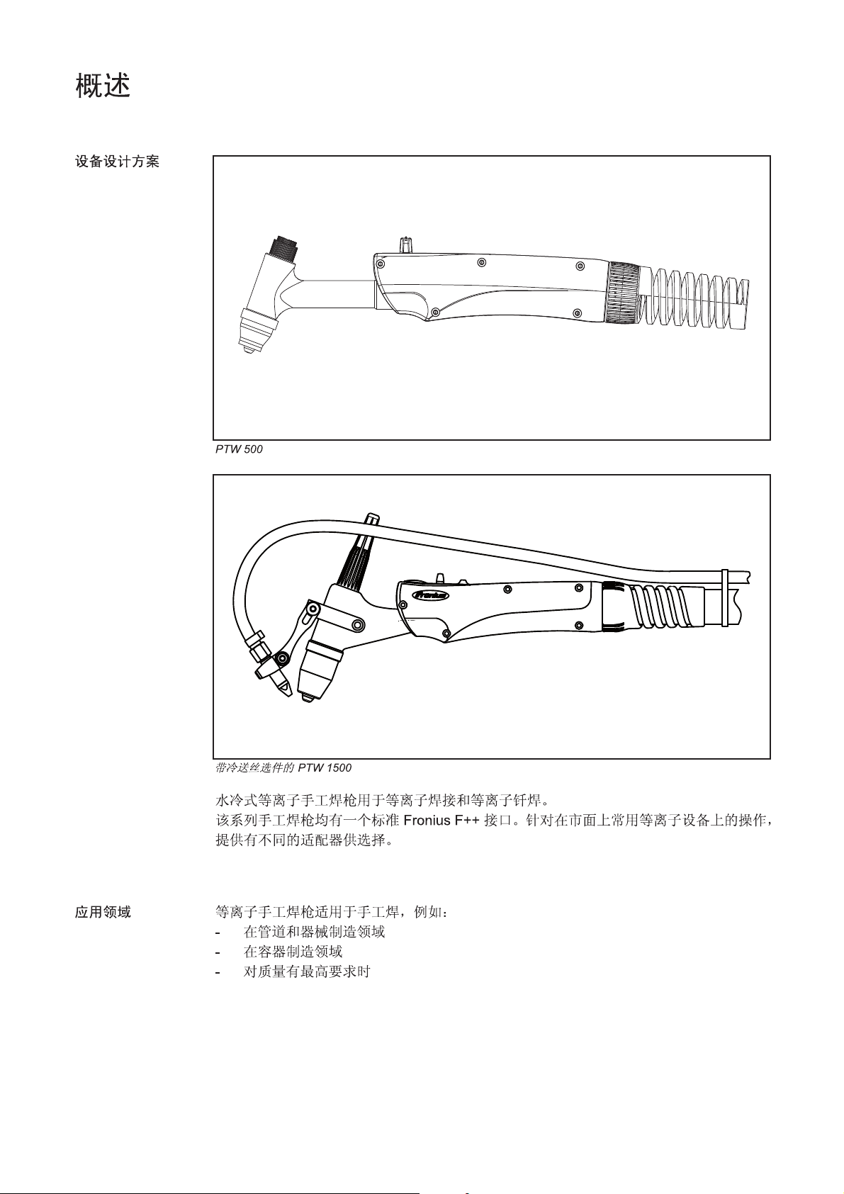
Gerätekonzept
PTW 500
PTW 1500 mit Option Kaltdraht-Zuführung
Die wassergekühlten Plasma Hand-Schweißbrenner dienen zum Plasmaschweißen und
zum Plasmalöten.
Die Hand-Schweißbrenner besitzen serienmäßig einen Fronius F++ Anschluss. Für den
Betrieb an einem handelsüblichen Plasma-Gerät stehen verschiedene Adapter zur Verfügung.
Einsatzgebiete Die Plasma Hand-Schweißbrenner kommen bei manuellen Anwendungen zum Einsatz,
z.B.:
- im Rohrleitungs- und Apparatebau
- im Behälterbau
- bei höchsten Qualitätsanforderungen
2
Page 7

Lieferumfang
Brennerkappe PTW 500
Brennerkörper
mit Anschlagring
Plasmadüse
∅ 1,2 mm
Schutzgasdüse
Lieferumfang PTW 500
Spannhülse ∅ 1 mm
Wolframelektrode WL 15, ∅ 1 mm
Keramik-Zentrierrohr
Brennerkappe PTW 1500
Einstell-Lehre
Schlauchpaket 4 m,
Fronius F++ / FG Anschluss
DE
Optionen PTW
500
Spannhülse ∅ 2,4 mm
Brennerkörper
mit Anschlagring
Wolframelektrode WL 15, ∅ 2,4 mm
Keramik-Zentrierrohr
Plasmadüse ∅ 2,5 mm
Schutzgasdüse
Lieferumfang PTW 1500
- Plasmadüse 0,6 / 0,8 / 1 / 1,4 / 1,6 / 1,8
- Adapter für das nicht digitale PlasmaModul
Einstell-Lehre
∅ 2,5 - 3 mm
Schlauchpaket 4 m,
Fronius F++ / FG Anschluss
Optionen PTW
1500
- Einstell-Lehre ∅ 1,5 - 2 mm
- Kaltdraht-Zuführung (Push-System): Robacta Plasma KD
- Plasmadüse 1 / 1,5 / 2 / 3 mm
- Keramik-Zentrierrohr 1,6 / 3,2 mm
- Spannhülse 1,6 / 3,2 mm
- Adapter für das nicht digitale PlasmaModul
3
Page 8

PTW 500 / 1500 montieren
Sicherheit
PTW 500 montieren
WARNUNG! Fehlerhaft durchgeführte Arbeiten können schwerwiegende
Personen und Sachschäden verursachen. Nachfolgend beschriebene Tätigkeiten dürfen nur von geschultem Fachpersonal durchgeführt werden! Beachten
Sie die Sicherheitsvorschriften.
1 2
Spannhülse einsetzen
5
4
3
2
1
2
Wolframelektrode einsetzen
2x360°
3
1
Wichtig! Die Wolframelektrode so einsetzen, dass die Spitze ca. 10 mm aus dem
Brennerkörper ragt. Brennerkappe PTW 500 leicht anziehen, sodass die Wolframelektrode im Brennerkörper noch verschiebbar ist.
3
1
2
3
Zentrierrohr, Plasmadüse und Schutzgasdüse
montieren
4
Page 9

PTW 1500 montieren
1
3
2
1
2
DE
2
1
Spannhülse einsetzen
Wolframelektrode einsetzen
Wichtig! Die Wolframelektrode so einsetzen, dass die Spitze ca. 10 mm aus dem
Brennerkörper ragt. Brennerkappe PTW 1500 leicht anziehen, sodass die Wolframelektrode im Brennerkörper noch verschiebbar ist.
3
1
2
3
10 mm
∼
Zentrierrohr, Plasmadüse und Schutzgasdüse
montieren
5
Page 10

Wolframelektrode einstellen
Allgemeines
Wolframelektrode
einstellen PTW
500
Die Position der Wolframelektrode ist neben der eingestellten Plasmagas-Menge ausschlaggebend für die Belastungsgrenzen.
Unter Belastungsgrenzen versteht man den maximal möglichen Schweißstrom
- bei einer bestimmten Plasmadüse,
- bei einer bestimmten Plasmagas-Menge,
- bei einer bestimmten Position der Wolframelektrode (nur bei PTW 1500).
Der Einstell-Vorgang für die Wolframelektrode zum Plasma-Schweißen / Plasma-Löten
wird im folgenden Abschnitt beschrieben.
WARNUNG! Fehlerhaft durchgeführte Arbeiten können schwerwiegende
Personen und Sachschäden verursachen. Nachfolgend beschriebene Tätigkeiten dürfen nur von geschultem Fachpersonal durchgeführt werden! Beachten
Sie die Sicherheitsvorschriften.
1 2
3
2
4
*
1
Brennerkappe lockern - je nach Brennerstellung
darauf achten, dass die Wolframelektrode nicht aus
dem Plasmabrenner fällt!
3
1
1
0
2x360°
1
2
4
4
1
2
Wolframelektrode mit Hilfe der Einstell-Lehre
justieren
6
3
Wolframelektrode mittels Brennerkappe fixieren
Page 11

Einstell-Lehre
PTW 1500 justieren
1
1
2
3
X
Einstell-Lehre PTW 1500 auf Maß „x“ justieren
HINWEIS! Die Standard-Einstellung für das Maß „x“ an der
jeweiligen Einstell-Lehre ist
abhängig vom Durchmesser der
Plasmadüse. Standard-Einstellung für das Maß „x“ gemäß
folgender Tabelle einstellen:
∅ ∅
∅ Plasmadüse „x“ Einstell-Lehre
∅ ∅
1,5 mm 1,5 mm ∅ 1,5 - 2 mm
2,0 mm 2,0 mm ∅ 1,5 - 2 mm
2,5 mm 2,5 mm ∅ 2,5 - 3 mm
3,0 mm 2,5 mm ∅ 2,5 - 3 mm
DE
Wolframelektrode
einstellen PTW
1500
2
2
Brennerkappe lockern - je nach Brennerstellung
darauf achten, dass die Wolframelektrode nicht aus
dem Plasmabrenner fällt!
4
3
1
Einstell-Lehre an der Plasmadüse ansetzen ...
5
1
... und Wolframelektrode einrichten
2
Wolframelektrode mittels Brennerkappe fixieren
7
Page 12

Inbetriebnahme
WARNUNG! Fehlbedienung kann schwerwiegende Personen- und Sachschä-
den verursachen. Beschriebene Funktionen erst anwenden, wenn folgende
Dokumente vollständig gelesen und verstanden wurden:
- diese Bedienungsanleitung
- sämtliche Bedienungsanleitungen der Systemkomponenten, insbesondere
Sicherheitsvorschriften
Allgemeines
Bestimmungsgemäße Verwendung
Der Plasmabrenner ist ausschließlich zum manuellen Plasma-Schweißen und PlasmaLöten bestimmt.
Eine andere oder darüber hinausgehende Benutzung gilt als nicht bestimmungsgemäß.
Für hieraus entstehende Schäden haftet der Hersteller nicht.
Zur bestimmungsgemäßen Verwendung gehört auch
- das Beachten aller Hinweise aus der Bedienungsanleitung
- die Einhaltung der Inspektions- und Wartungsarbeiten
Inbetriebnahme 1. Plasmabrenner kontrollieren, ob:
- alle Teile vorhanden sind
- die Teile richtig montiert wurden
HINWEIS! Eine falsch eingestellte Wolframelektrode kann die Plasmadüse bei
Inbetriebnahme beschädigen! Wolframelektrode entsprechend der Plasmadüse
und gemäß der jeweiligen Anwendung einstellen!
2. Wolframelektrode mittels Einstell-Lehre einstellen
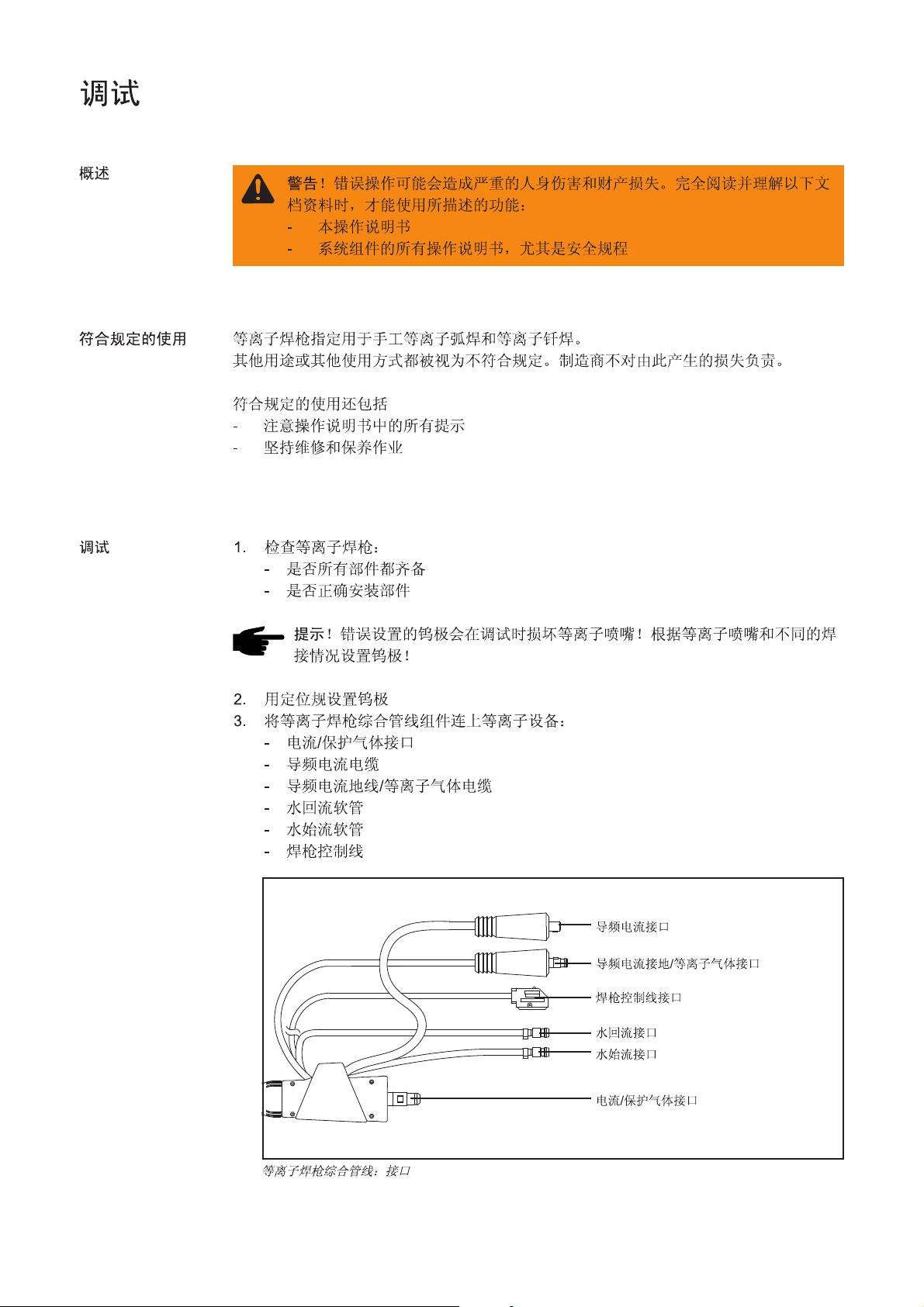
3. Komponenten des Plasmabrenner-Schlauchpaketes am Plasmagerät anschließen:
- Anschluss für Strom / Schutzgas
- Kabel für Pilotstrom
- Kabel für Pilotstrom-Masse / Plasmagas
- Schlauch für Wasserrücklauf
- Schlauch für Wasservorlauf
- Kabel für die Brennersteuerung
Plasmabrenner-Schlauchpaket: Anschlüsse
8
Anschluss Pilotstrom
Anschluss Pilotstrom-Masse / Plasmagas
Anschluss Brennersteuerung
Anschluss Wasserrücklauf
Anschluss Wasserrvorlauf
Anschluss Strom / Schutzgas
Page 13

Inbetriebnahme
VORSICHT! Verletzungs- und Brandgefahr durch gezündeten Pilot-Lichtbogen.
Plasma-Schweißbrenner mit gezündetem Pilot-Lichtbogen von brennbaren und
entflammbaren Materialien sowie von Personen oder Körperteilen fernhalten.
Nicht in den Pilot-Lichtbogen greifen.
(Fortsetzung)
4. Bei Erstinbetriebnahme auf korrekte Gasströmung achten
5. Schutzgas und Plasmagas für mindestens 30 sec. spülen
DE
HINWEIS! Der Plasmabrenner muss während des Betriebes ständig gekühlt
werden.
6. Kühl-Kreislauf der Plasma-Anlage auf richtige Funktion überprüfen, Kühlgerät auf
Dauerbetrieb einstellen (z.B.: SetUp-Menü an der Stromquelle, Parameter
C-C = ON)
HINWEIS! Ein Zünden des Pilot-Lichtbogens ohne voreingestelltes Plasmagas
kann die Verschleißteile Plasmadüse, Keramik-Zentrierrohr und Wolframelektrode beschädigen.
7. Plasmagas-Menge am Plasmagerät einstellen (abhängig vom Durchmesser der
Plasmadüse und der jeweiligen Anwendung)
8. Pilot-Lichtbogen zünden
Wichtig! Der Pilot-Lichtbogen soll aus Verschleißgründen während der ganzen Betriebszeit brennen.
9. Schweißbeginn durch Betätigen der Brennertaste
9
Page 14

Belastungsgrenzen in Abhängigkeit von der Plasmagas-Menge
Allgemeines Belastungsgrenzen beim Plasmaschweißen / Plasmalöten hängen von folgenden Fakto-
ren ab:
- Durchmesser der Plasmadüse
- Plasmagas-Menge
- Position der Wolframelektrode
Die folgenden Belastungsgrenzen gelten bei Standardeinstellung der Wolframelektrode
(siehe auch Abschnitt „Wolframelektrode einstellen“).
Belastungsgrenzen in Abhängigkeit von der
PlasmagasMenge
Zum Plasmaschweißen müssen die eingestellten Werte für Plasmagas-Menge und
maximalen Schweißstrom innerhalb der angegebenen Grenzwerte liegen. Ein Unteroder Überschreiten dieser Grenzwerte bringt eine Veränderung der Plasmaeigenschaften mit sich, z.B.:
- Geringe Plasmagas-Menge ........ „weicher“ Plasmastrahl
- Hohe Plasmagas-Menge............. „harter“ Plasmastrahl („Plasmaschneiden“)
Wichtig! Grenzwerte für Plasmagas-Werte und max. Schweißstrom während des
Betriebes nicht unter- oder überschreiten.
Wichtig! Die Kühlmittel-Mindestdurchflussmenge beträgt 1 l / min.
Tabelle gilt nur für PTW 500 (Elektrodendurchmesser 1,0 mm; ED 60%):
∅∅
∅ Plasmadüse Plasmagas-Menge max. Schweißstrom
∅∅
0,6 mm min. 0,3 l/min 15 A
0,8 mm min. 0,3 l/min 20 A
1 mm min. 0,3 l/min 28 A
1,2 mm min. 0,3 l/min 35 A
1,4 mm min. 0,3 l/min 45 A
1,6 mm min. 0,3 l/min 50 A
1,8 mm min. 0,3 l/min 50 A
Tabelle gilt nur für PTW 1500:
∅∅
∅ Plasmadüse Plasmagas-Menge max. Schweißstrom
∅∅
1,5 mm min. 0,30 l/min 60 A
max. 0,80 l/min 100 A
2,0 mm min. 0,35 l/min 80 A
max. 1,00 l/min 120 A
2,5 mm min. 0,45 l/min 110 A
max. 1,20 l/min 145 A
3,0 mm min. 0,55 l/min 130 A
max. 1,30 l/min 150 A
Minimale Plasmagas-Menge:
Gasmenge, bei der der Schweiß-Lichtbogen gerade noch stabil brennt.
Maximale Plasmagas-Menge:
Gasmenge, die je nach Plasmadüse das Arbeiten mit dem maximalen Schweißstrom
ermöglicht.
10
Page 15

Belastungsgrenzen in Abhängigkeit von der
PlasmagasMenge
(Fortsetzung)
Maximaler Schweißstrom:
zulässiger Schweißstrom bei
- einer bestimmten Plasmadüse
- Standardeinstellung der Wolframelektrode
- minimaler oder maximaler Plasmagas-Menge
Beispiel PTW 1500:
Bei einer Plasmadüse mit einem Durchmesser von 2,0 mm, einer eingestellten MindestPlasmagas-Menge von 0,25 l/min ist bei Standardeinstellung der Wolframelektrode ein
maximaler Schweißstrom von 80 A zulässig.
Wichtig! Als Plasmagas ausschließlich reines Argon verwenden! Nur reines Argon gewährleistet das Erreichen der oben angeführten Grenzwerte.
DE
11
Page 16

Fehlerdiagnose - Fehlerbehebung
WARNUNG! Ein elektrischer Schlag kann tödlich sein. Vor Arbeiten am Plasma-
brenner:
- Netzschalter von Stromquelle und Plasmagerät in Stellung - O - schalten
- Stromquelle und Plasmagerät vom Netz trennen
- ein verständliches Warnschild gegen Wiedereinschalten anbringen
Sicherheit
Fehlerdiagnose Fehlerbehebung
Pilot-Lichtbogen zündet nicht
Ursache: Wolframelektrode fehlt
Behebung: Wolframelektrode einsetzen
Ursache: Zu großer Abstand zwischen Plasmadüse und Wolframelektrode
Behebung: Wolframelektrode richtig positionieren
Ursache: Kein oder zu geringer Abstand zwischen Plasmadüse und Wolframelektro-
de (Kurzschluss zwischen Plasmadüse und Wolframelektrode)
Behebung: Wolframelektrode richtig positionieren
Kupfertropfen auf der Plasmadüse nach kurzer Schweißzeit
Tropfenbildung auf der Plasmadüse ist ein Zeichen für eine starke Beschädigung der
Plasmadüse: das in der Plasmadüse enthaltene Kupfer wird auf Grund zu hoher Temperaturen aufgeschmolzen und läuft aus.
Ursache: zu hohe Belastungswerte
Behebung: Plasmadüse wechseln, Belastung reduzieren
12
Page 17

Pflege, Wartung und Entsorgung
WARNUNG! Ein elektrischer Schlag kann tödlich sein. Vor Arbeiten am Plasma-
brenner:
- Netzschalter von Stromquelle und Plasmagerät in Stellung - O - schalten
- Stromquelle und Plasmagerät vom Netz trennen
- ein verständliches Warnschild gegen Wiedereinschalten anbringen
DE
Allgemeines
Bei jeder Inbetriebnahme
Regelmäßige und vorbeugende Wartung des Plasmabrenners sind wesentliche Faktoren für einen störungsfreien Betrieb. Der Plasmabrenner ist hohen Temperaturen ausgesetzt. Daher benötigt der Plasmabrenner eine häufigere Wartung als andere Komponenten einer Plasma-Schweißanlage.
- Plasmabrenner, Brenner-Schlauchpaket und Stromanschlüsse auf Beschädigung
prüfen
- Gas- und Wasseranschlüsse auf Dichtheit prüfen
- Kühlgerät zur Kühlung des Plasmabrenners auf einwandfreie Funktion überprüfen,
Wasser-Rückflussmenge im Kühlmittel-Behälter überwachen, gegebenenfalls
Kühlgerät entlüften
- Plasmabrenner-Verschleißteile auf einwandfreien Zustand prüfen, Verschleißteile
vor dem Einbau reinigen
Monatlich - Falls vorhanden, Filter im Kühl-Kreislauf auf Verunreinigung prüfen
- Kühlmittel auf Reinheit prüfen; bei Verunreinigung Kühlmittel austauschen und
Plasmabrenner über Kühlmittel-Vorlauf und Kühlmittel-Rücklauf mehrmals durchspülen
HINWEIS! Ablagerungen im Inneren des Plasmabrenners können Hochfrequenz-Überschläge verursachen und somit den Plasmabrenner beschädigen.
- Plasmabrenner zerlegen und auf Ablagerungen / Verunreinigungen prüfen
Entsorgung Die Entsorgung nur gemäß den geltenden nationalen und regionalen Bestimmungen
durchführen.
13
Page 18

Technische Daten
PTW 500, PTW
1500
PTW 500 PTW 1500
Leistungsbereich 0,5 - 50 A 3 - 150 A
Maximalwert bei 60 % ED 50 A Maximalwert bei 100 % ED 35 A 150 A
Strom Pilotlichtbogen 5 A 10 A
Spannungsbemessung (V-Peak) 141 V 141 V
Plasmagas / Schutzgas (lt. EN 439) Argon Argon
Schlauchpaket-Länge 4 m 4 / 6 m
Elektroden-Durchmesser 1 mm 1,6 - 3,2 mm
Kühlsystem *) *)
Kühlmittel **) **)
Kühlleistung ***) 500 W 700 / 1000 W
Kühlmitteldruck min. 3,0 bar 3,0 bar
43,50 psi 43,50 psi
Kühlmitteldruck max. 5,5 bar 5,5 bar
79,74 psi 79,74 psi
Kühlmittel-Mindestdurchfluss 1,0 l/min 1,0 l/min
*) Flüssigkeitskühlung
**) Original Fronius-Kühlmittel
***) Geringste Kühlleistung laut Norm IEC 60974-2
Das Produkt entspricht den Anforderungen laut Norm IEC 60974-7
14
Page 19

Dear Reader
Introduction
Thank you for choosing Fronius - and congratulations on your new, technically highgrade Fronius product! This instruction manual will help you get to know your new
machine. Read the manual carefully and you will soon be familiar with all the many
great features of your new Fronius product. This really is the best way to get the most
out of all the advantages that your machine has to offer.
Please also take special note of the safety rules - and observe them! In this way, you
will help to ensure more safety at your product location. And of course, if you treat your
product carefully, this definitely helps to prolong its enduring quality and reliability - things
which are both essential prerequisites for getting outstanding results.
EN
ud_fr_st_et_00493 01/2012
Page 20

Page 21

Contents
General .......................................................................................................................................................... 2
Device concept ......................................................................................................................................... 2
Application areas ...................................................................................................................................... 2
Scope of supply ........................................................................................................................................ 3
PTW 500 options ...................................................................................................................................... 3
PTW 1500 options .................................................................................................................................... 3
Assembling the PTW 500/1500 ..................................................................................................................... 4
Safety ....................................................................................................................................................... 4
Assembling the PTW 500 ......................................................................................................................... 4
Assembling the PTW 1500 ....................................................................................................................... 5
Adjusting the tungsten electrode ................................................................................................................... 6
General ..................................................................................................................................................... 6
Adjusting the PTW 500 tungsten electrode............................................................................................... 6
Calibrating the PTW 1500 adjusting gauge ............................................................................................... 7
Adjusting the PTW 1500 tungsten electrode ............................................................................................. 7
Starting up ..................................................................................................................................................... 9
General ..................................................................................................................................................... 9
Proper use ................................................................................................................................................ 9
Starting up ................................................................................................................................................ 9
Loading limits dependent on the plasma gas flow rate .................................................................................. 11
General .................................................................................................................................................... 11
Loading limits dependent on the plasma gas flow rate ............................................................................. 11
EN
Troubleshooting ............................................................................................................................................12
Safety ......................................................................................................................................................12
Troubleshooting .......................................................................................................................................12
Care, maintenance and disposal ................................................................................................................... 13
General ....................................................................................................................................................13
Every start-up .......................................................................................................................................... 13
Monthly .................................................................................................................................................... 13
Disposal ...................................................................................................................................................13
Technical data...............................................................................................................................................14
PTW 500, PTW 1500 ............................................................................................................................... 14
1
Page 22

General
Device concept
PTW 500
PTW 1500 with cold wire feeder option
The water-cooled plasma manual welding torches are used for plasma welding and plasma
brazing.
The manual welding torches have a Fronius F++ connection as standard. Various adapters are available to enable the torches to be operated with any standard plasma device.
Application areas The plasma manual welding torch is used in manual applications, e.g.:
- Pipeline and equipment construction
- Container construction
- Applications requiring the highest quality standards
2
Page 23

Scope of supply
Torch cap PTW 500
Torch body
with stop ring
Ceramic centring tube
Plasma
nozzle ∅ 1.2
mm
Shielding gas
nozzle
PTW 500 scope of supply
Clamping sleeve ∅ 1 mm
Tungsten electrode WL 15, ∅ 1 mm
Torch cap PTW 1500
Adjusting
gauge
EN
Hosepack 4 m,
Fronius F++ / FG connection
Clamping sleeve ∅ 2.4
mm
Torch body
with stop ring
Tungsten electrode WL 15, ∅ 2.4 mm
Ceramic centring tube
Plasma nozzle ∅ 2.5
mm
Shielding gas
nozzle
PTW 1500 scope of supply
PTW 500 options - Plasma nozzle 0.6 / 0.8 / 1 / 1.4 / 1.6 / 1.8
- Adapter for the non-digital PlasmaModule
Adjusting
gauge
∅ 2.5 - 3 mm
Hosepack 4 m,
Fronius F++ / FG connection
PTW 1500 options - Adjusting gauge ∅ 1.5 - 2 mm
- Cold wire feeder (push system): Robacta Plasma KD
- Plasma nozzle 1 / 1.5 / 2 / 3 mm
- Ceramic centring tube 1.6 / 3.2 mm
- Clamping sleeve 1.6 / 3.2 mm
- Adapter for the non-digital PlasmaModule
3
Page 24

Assembling the PTW 500/1500
Safety
Assembling the
PTW 500
WARNING! Work that is carried out incorrectly can cause serious injury and
damage. The following activities may only be carried out by trained and qualified
personnel. Follow the safety regulations.
1 2
Insert clamping sleeve
5
4
3
2
1
2
Insert tungsten electrode
2x360°
3
1
Important Insert the tungsten electrode so that the tip protrudes approx. 10 mm out of
the torch body. Slightly tighten the PTW 500 torch cap so that the tungsten electrode can
still be moved inside the torch body.
3
1
2
3
Assemble centring tube, plasma nozzle and
shielding gas nozzle
4
Page 25

Assembling the
PTW 1500
1
3
2
1
2
2
EN
1
Insert clamping sleeve
Insert tungsten electrode
Important Insert the tungsten electrode so that the tip protrudes approx. 10 mm out of
the torch body. Slightly tighten the PTW 1500 torch cap so that the tungsten electrode
can still be moved inside the torch body.
3
1
2
3
10 mm
∼
Assemble centring tube, plasma nozzle and
shielding gas nozzle
5
Page 26

Adjusting the tungsten electrode
General
Adjusting the
PTW 500 tungsten electrode
Apart from the specified plasma gas flow rate, the position of the tungsten electrode plays
a crucial role in determining the loading limits.
By loading limits we mean the maximum possible welding current
- for a particular plasma nozzle,
- for a particular plasma gas flow rate,
- for a particular tungsten electrode (PTW 1500 only) position.
The setting process for the tungsten electrode for plasma welding / plasma brazing is
described in the following section.
WARNING! Work that is carried out incorrectly can cause serious injury and
damage. The following activities may only be carried out by trained and qualified
personnel. Follow the safety regulations.
1 2
2x360°
1
3
2
4
2
*
1
Loosen the torch cap - caution, the tungsten
electrode may fall out of the plasma torch if the
torch is in a particular position.
3
1
1
0
Calibrate the tungsten electrode using the
adjusting gauge
4
4
1
2
3
Fix the tungsten electrode in place using the torch
cap
6
Page 27

Calibrating the
PTW 1500 adjusting gauge
1
1
2
3
X
Calibrate PTW 1500 adjusting gauge to measurement „x“
NOTE! The standard setting for
measurement „x“ on the adjusting
gauge depends on the diameter of
the plasma nozzle. Refer to the
following table when adjusting the
standard setting for measurement
„x“:
∅ ∅
∅ Plasma nozzle „x“ Adjusting gauge
∅ ∅
1.5 mm 1.5 mm ∅ 1.5 - 2 mm
2.0 mm 2.0 mm ∅ 1.5 - 2 mm
2.5 mm 2.5 mm ∅ 2.5 - 3 mm
3.0 mm 2.5 mm ∅ 2.5 - 3 mm
EN
Adjusting the
PTW 1500 tungsten electrode
2
2
Loosen the torch cap - caution, the tungsten
electrode may fall out of the plasma torch if the
torch is in a particular position.
4
3
1
Place adjusting gauge onto plasma nozzle ...
5
1
... and adjust tungsten electrode
2
Fix the tungsten electrode in place using the torch
cap
7
Page 28

Starting up
WARNING! Incorrect operation may result in serious injury or damage. Do not
use the functions described here until you have thoroughly read and understood
the following documents:
- these Operating Instructions
- all the operating instructions for the system components, especially the
safety rules
General
Proper use
The plasma torch is intended exclusively for manual plasma welding and plasma brazing.
Any use above and beyond this purpose is deemed improper. The manufacturer shall not
be held liable for any damage arising from such usage.
Proper use also includes:
- following all the instructions in these operating instructions
- performing all stipulated inspection and servicing work
Starting up 1. Check plasma torch to see whether:
- all parts are present
- the parts have been correctly fitted
NOTE! An incorrectly adjusted tungsten electrode can damage the plasma
nozzle during start-up. Adjust the tungsten electrode according to the plasma
nozzle used and the application.
2. Adjust the tungsten electrode using the adjusting gauge
3. Connect the components of the plasma torch hosepack to the plasma device:
- Current/shielding gas connection
- Pilot flow cable
- Cable for pilot flow mass/plasma gas
- Water return hose
- Water flow hose
- Torch control cable
Plasma torch hosepack: connections
8
Pilot flow connection
Pilot flow mass / plasma gas connection
Torch control connection
Water return connection
Water flow connection
Current/shielding gas connection
Page 29

Starting up
CAUTION! Risk of injury and fire from ignited pilot arc. Keep plasma torch with
ignited pilot arc away from flammable materials and people and parts of the
body. Keep hands away from the pilot arc.
(continued)
4. When starting up for the first time, make sure the gas flow is correct
5. Purge shielding gas and plasma gas for at least 30 seconds
NOTE! The plasma torch must be cooled constantly during operation.
6. Check that the cooling circuit on the plasma machine is functioning correctly and set
the cooling unit to permanent operation (e.g. set-up menu on power source, parameter
C-C =ON)
NOTE! Igniting the pilot arc without presetting the plasma gas can damage the
plasma nozzle, ceramic centring tube and tungsten electrode (all wearing parts).
7. Set the plasma gas flow rate at the plasma device (according to the diameter of the
plasma nozzle and the application)
8. Ignite pilot arc
Important To reduce wear, the pilot arc should burn throughout the operation.
9. Actuate the torch trigger to begin welding
EN
9
Page 30

Loading limits dependent on the plasma gas flow
rate
General Loading limits for plasma welding/plasma brazing depend on the following factors:
- Diameter of the plasma nozzle
- Plasma gas flow rate
- Position of the tungsten electrode
The following loading limits apply to the standard tungsten electrode setting (see also
section entitled „Adjusting the tungsten electrode“).
Loading limits
dependent on the
plasma gas flow
rate
For plasma welding, the values for the plasma gas flow rate and maximum welding current
must lie within the set limits. An upper or lower exceed of these limits can change the
plasma properties, e.g.:
- Low plasma gas flow rate .............„soft“ plasma jet
- High plasma gas flow rate............ „hard“ plasma jet („plasma cutting“)
Important Do not exceed the upper or lower limits set for plasma gas values and max.
welding current during operation.
Important The minimum coolant flow rate is 1 l/min.
This table is only valid for the PTW 500 (electrode diameter 1.0 mm; d.c. 60%):
∅∅
∅ Plasma nozzle Plasma gas flow rate Max. welding current
∅∅
0.6 mm min. 0.3 l/min 15 A
0.8 mm min. 0.3 l/min 20 A
1 mm min. 0.3 l/min 28 A
1.2 mm min. 0.3 l/min 35 A
1.4 mm min. 0.3 l/min 45 A
1.6 mm min. 0.3 l/min 50 A
1.8 mm min. 0.3 l/min 50 A
This table is only valid for the PTW 1500:
∅∅
∅ Plasma nozzle Plasma gas flow rate Max. welding current
∅∅
1.5 mm min.0.30 l/min 60 A
max.0.80 l/min 100 A
2.0 mm min.0.35 l/min 80 A
max.1.00 l/min 120 A
2.5 mm min.0.45 l/min 110 A
max.1.20 l/min 145 A
3.0 mm min.0.55 l/min 130 A
max.1.30 l/min 150 A
Minimum plasma gas flow rate:
Amount of gas at which the welding arc still remains stable.
Maximum plasma gas flow rate:
Gas flow rate that makes working with the maximum welding current possible, depending
on the plasma nozzle.
10
Page 31

Loading limits
dependent on the
plasma gas flow
rate
(continued)
Maximum welding current:
Permitted welding current for
- a particular plasma nozzle
- standard tungsten electrode setting
- minimum or maximum plasma gas flow rate
Example PTW 1500: in the case of a plasma nozzle with a diameter of 2.0 mm and a
specified minimum plasma gas flow rate of 0.25 l/min, a maximum welding current of 80 A
is permitted for the standard tungsten electrode setting.
Important For plasma gas use pure argon only. The limit values listed above can only be
obtained using pure argon.
EN
11
Page 32

Troubleshooting
WARNING! An electric shock can be fatal. Before carrying out any work on the
plasma torch:
- switch the power source and plasma device mains switch to the „O“ position
- disconnect the power source and plasma device from the mains
- put up an easy-to-understand warning sign to stop anybody inadvertently
switching it back on again
Safety
Troubleshooting
Pilot arc not igniting
Cause: Tungsten electrode missing
Remedy: Insert tungsten electrode
Cause: Plasma nozzle and tungsten electrode too far apart
Remedy: Position tungsten electrode correctly
Cause: Plasma nozzle and tungsten electrode touching or too close (short circuit
between plasma nozzle and tungsten electrode)
Remedy: Position tungsten electrode correctly
Copper droplets on the plasma nozzle after a short welding time
Droplet formation on the plasma nozzle is a sign that it is badly damaged: the copper in
the plasma nozzle has melted as a result of excess temperatures and is escaping.
Cause: Loading values too high
Remedy: Replace plasma nozzle, reduce load
12
Page 33

Care, maintenance and disposal
WARNING! An electric shock can be fatal. Before carrying out any work on the
plasma torch:
- switch the power source and plasma device mains switch to the „O“ position
- disconnect the power source and plasma device from the mains
- put up an easy-to-understand warning sign to stop anybody inadvertently
switching it back on again
General
Every start-up - Check plasma torch, torch hosepack and current connections for signs of damage
Regular and preventive maintenance of the plasma torch is essential for problem-free
operation. The plasma torch is subjected to high temperatures. The plasma torch therefore requires more frequent maintenance than other components in a plasma welding
system.
- Check gas and water connections for leaks
- Check that the cooling unit used for cooling the plasma torch is functioning properly,
monitor the water return level in the coolant container, and vent the cooling unit if
necessary
- Check that the wearing parts for the plasma torch are in perfect condition, clean
wearing parts before fitting them
EN
Monthly - If applicable, check filter in the cooling circuit for contamination.
- Check that coolant is pure; if there are any impurities, replace the coolant and rinse
the plasma torch thoroughly several times by letting coolant flow into it and back out
again
NOTE! Deposits inside the plasma torch can cause high frequency arc-overs that
will damage the plasma torch.
- Dismantle the plasma torch and check for deposits/contamination
Disposal Dispose of in accordance with the applicable national and local regulations.
13
Page 34

Technical data
PTW 500, PTW
1500
PTW 500 PTW 1500
Power range 0.5 - 50 A 3 - 150 A
Maximum value at 60 % d.c. (duty cycle) 50 A Maximum value at 100 % d.c. (duty cycle) 35 A 150 A
Pilot arc current 5 A 10 A
Voltage measurement (V-Peak) 141 V 141 V
Plasma gas/shielding gas (according to EN 439) Argon Argon
Length of hosepack 4 m 4/6 m
Electrode diameter 1 mm 1.6 - 3.2 mm
Cooling system *) *)
Coolant **) **)
Cooling power ***) 500 W 700/1000 W
Min. coolant pressure 3.0 bar 3.0 bar
43.50 psi 43.50 psi
Max. coolant pressure 5.5 bar 5.5 bar
79.74 psi 79.74 psi
Minimum coolant flow rate 1.0 l/min 1.0 l/min
*) Liquid cooling
**) Original Fronius coolant
***) Lowest cooling power according to IEC 60974-2 standard
The product conforms to the requirements of the IEC 60974-7 standard
14
Page 35

Cher lecteur
Introduction
Nous vous remercions de votre confiance et vous félicitons d’avoir acheté un produit de
qualité supérieure de Fronius. Les instructions suivantes vous aideront à vous familiariser avec le produit. En lisant attentivement les instructions de service suivantes, vous
découvrirez les multiples possibilités de votre produit Fronius. C’est la seule manière
d’exploiter ses avantages de manière optimale.
Prière d’observer également les consignes de sécurité pour garantir une sécurité accrue
lors de l’utilisation du produit. Une utilisation soigneuse du produit contribue à sa longévité et sa fiabilité. Ce sont des conditions essentielles pour obtenir d’excellents résultats.
FR
ud_fr_st_et_00500 01/2012
Page 36

Page 37

Sommaire
Généralités .................................................................................................................................................... 2
Concept de l’appareil ................................................................................................................................ 2
Applications .............................................................................................................................................. 2
Livraison ................................................................................................................................................... 3
Options PTW 500 ..................................................................................................................................... 3
Options PTW 1500 ................................................................................................................................... 3
Monter le PTW 500 / 1500 ............................................................................................................................. 4
Sécurité .................................................................................................................................................... 4
Monter le PTW 500 ................................................................................................................................... 4
Monter le PTW 1500 ................................................................................................................................. 5
Régler l’électrode tungstène .......................................................................................................................... 6
Généralités ............................................................................................................................................... 6
Régler l’électrode en tungstène PTW 500 ................................................................................................. 6
Ajuster le gabarit de réglage PTW 1500 .................................................................................................... 7
Régler l’électrode en tungstène PTW 1500 ............................................................................................... 7
Mise en service .............................................................................................................................................. 9
Généralités ............................................................................................................................................... 9
Utilisation conforme à la destination ......................................................................................................... 9
Mise en service......................................................................................................................................... 9
Limites de charge en fonction de la quantité de plasma de gaz ....................................................................11
Généralités .............................................................................................................................................. 11
Limites de charge en fonction de la quantité de plasma de gaz ............................................................... 11
FR
Diagnostic d’erreur - Élimination de l’erreur...................................................................................................12
Sécurité ...................................................................................................................................................12
Diagnostic d’erreur - Élimination de l’erreur..............................................................................................12
Maintenance, entretien et élimination ...........................................................................................................13
Généralités ..............................................................................................................................................13
À chaque mise en service ........................................................................................................................13
Tous les mois ..........................................................................................................................................13
Élimination...............................................................................................................................................13
Caractéristiques techniques .........................................................................................................................14
PTW 500, PTW 1500 ............................................................................................................................... 14
1
Page 38

Généralités
Concept de
l’appareil
PTW 500
Domaines
d’application
PTW 1500 avec option alimentation de fil froid
Les torches de soudage manuel plasma refroidies par eau sont utilisées pour le soudage
à l’arc plasma et le brasage plasma.
De série, les torches de soudage manuel sont équipées d’un raccord Fronius F++. Divers
adaptateurs sont disponibles pour utilisation sur un appareil plasma usuel du commerce.
La torche de soudage manuel plasma s’utilise pour les applications automatisées, par
exemple :
- dans la construction de conduites et d’appareils
- dans la construction de conteneurs
- si des exigences de qualité élevées sont imposées
2
Page 39

Livraison
Cache de torche PTW 500
Corps de torche
avec bague de
butée
Buse plasma
∅ 1,2 mm
Buse gaz de
protection
Livraison PTW 500
Douille de serrage ∅ 1
mm
Électrode tungstène WL 15, ∅ 1 mm
Tube de centrage céramique
Cache de torche PTW 1500
Gabarit de réglage
FR
Faisceau de liaison 4 m
Raccord Fronius F++ / FG
Douille de serrage ∅ 2,4
mm
Corps de torche
avec bague de
butée
Électrode tungstène WL 15, ∅ 2,4 mm
Tube de centrage céramique
Buse plasma ∅ 2,5 mm
Buse gaz de
protection
Livraison PTW 1500
Options PTW 500 - Buse plasma 0,6 / 0,8 / 1 / 1,4 / 1,6 / 1,8
- Adaptateur pour le PlasmaModul non numérique
Gabarit de
réglage
∅ 2,5 - 3 mm
Faisceau de liaison 4 m
Raccord Fronius F++ / FG
Options PTW
1500
- Gabarit de réglage ∅ 1,5 - 2 mm
- Alimentation de fil froid (système Push) : Robacta Plasma KD
- Buse plasma 1 / 1,5 / 2 / 3 mm
- Tube de centrage céramique 1,6 / 3,2 mm
- Douille de serrage 1,6 / 3,2 mm
- Adaptateur pour le PlasmaModul non numérique
3
Page 40

Monter le PTW 500 / 1500
Sécurité
Monter le PTW
500
AVERTISSEMENT ! Les erreurs en cours d’opération peuvent entraîner des
dommages corporels et matériels graves. Les opérations décrites ci-après
doivent être effectuées exclusivement par du personnel qualifié et formé ! Respectez les consignes de sécurité.
1 2
Mise en place de la douille de serrage
5
4
3
2
1
2
Mise en place de l’électrode tungstène
2x360°
3
1
Important ! Insérer l’électrode de tungstène de manière à ce que la pointe dépasse d’env.
10 mm hors du corps de la torche. Serrer légèrement le cache de torche PTW 500 afin
que l’électrode au tungstène puisse encore coulisser dans le corps de la torche.
3
1
2
3
Montage du tube de centrage, de la buse plasma
et de la buse gaz de protection
4
Page 41

Monter le PTW
1500
1
3
2
1
2
2
1
FR
Mise en place de la douille de serrage
Mise en place de l’électrode tungstène
Important ! Insérer l’électrode de tungstène de manière à ce que la pointe dépasse d’env.
10 mm hors du corps de la torche. Serrer légèrement le cache de torche PTW 1500 afin
que l’électrode au tungstène puisse encore coulisser dans le corps de la torche.
3
1
2
3
10 mm
∼
Montage du tube de centrage, de la buse plasma
et de la buse gaz de protection
5
Page 42

Régler l’électrode tungstène
Généralités
Régler
l’électrode en
tungstène PTW
500
Outre la quantité de plasma de gaz paramétrée, la position de la torche plasma est
déterminante pour les limites de charge.
Par limites de charge, on entend l’intensité de courant maximale possible
- pour une buse plasma déterminée,
- pour une quantité de plasma de gaz déterminée,
- pour une position déterminée de l’électrode en tungstène (uniquement sur le PTW
1500).
La procédure de réglage de l’électrode tungstène pour le soudage à l’arc plasma / le
brasage plasma est décrite dans le paragraphe suivant.
AVERTISSEMENT ! Les erreurs en cours d’opération peuvent entraîner des
dommages corporels et matériels graves. Les opérations décrites ci-après
doivent être effectuées exclusivement par du personnel qualifié et formé ! Respectez les consignes de sécurité.
1 2
3
2
4
*
1
Desserrer la cache de torche - en fonction de la
position de la torche, veiller à ce que l’électrode
ne tombe pas de la torche plasma !
3
1
1
0
2x360°
1
2
4
4
1
2
Ajuster l’électrode en tungstène à l’aide du
gabarit de réglage
6
3
Fixer l’électrode en tungstène à l’aide du cache
de torche
Page 43

Ajuster le gabarit
de réglage PTW
1500
1
1
2
3
X
Ajuster le gabarit de réglage PTW 1500 sur la
mesure « x »
REMARQUE ! Le réglage de base
pour la mesure « x » sur le gabarit
de réglage correspondant est
fonction du diamètre de la buse
plasma. Ajuster le réglage de
base pour la mesure « x » conformément au tableau suivant :
∅ ∅
∅ Buse « x » Gabarit de
∅ ∅
plasma réglage
1,5 mm 1,5 mm ∅ 1,5 - 2 mm
2,0 mm 2,0 mm ∅ 1,5 - 2 mm
2,5 mm 2,5 mm ∅ 2,5 - 3 mm
3,0 mm 2,5 mm ∅ 2,5 - 3 mm
FR
Régler
l’électrode en
tungstène PTW
1500
2
2
Desserrer la cache de torche - en fonction de la
position de la torche, veiller à ce que l’électrode
ne tombe pas de la torche plasma !
4
3
1
Mettre en place le gabarit de réglage sur la buse
plasma ...
5
1
... et régler l’électrode en tungstène
2
Fixer l’électrode en tungstène à l’aide du cache
de torche
7
Page 44

Mise en service
AVERTISSEMENT ! Les erreurs de manipulation peuvent entraîner des dom-
mages corporels et matériels graves. N’utiliser les fonctions décrites qu’après
avoir lu et compris l’intégralité des documents suivants :
- les présentes instructions de service
- toutes les instructions de service des composants périphériques, en particulier les consignes de sécurité
Généralités
Utilisation conforme à la destination
La torche plasma est exclusivement destinée au soudage manuel à l’arc plasma et au
brasage plasma.
Toute autre utilisation sera considérée non conforme. Le fabricant ne saurait être tenu
pour responsable des dommages consécutifs.
Font également partie de l’emploi conforme
- le respect de toutes les indications des instructions de service
- le respect des travaux d’inspection et de maintenance
Mise en service 1. Sur la torche plasma, vérifier :
- la présence de toutes les pièces
- le montage correct des pièces
REMARQUE ! Une électrode en tungstène mal réglée risque d’endommager la
buse plasma lors de la mise en service ! Régler l’électrode tungstène en fonction
de la buse plasma et de l’application respective !
2. Ajuster l’électrode tungstène à l’aide du gabarit de réglage
3. Raccorder les composants du faisceau de liaison de la torche plasma à l’appareil
plasma :
- Raccord pour courant / gaz de protection
- Câble pour courant pilote
- Câble pour masse courant pilote / plasma de gaz
- Tuyau pour retour d’eau
- Tuyau pour arrivée d’eau
- Câble pour la commande de la torche
Faisceau de liaison torche plasma : Raccords
8
Raccord arc pilote
Raccord arc pilote Masse / plasma de gaz
Raccord commande de la torche
Raccord retour d’eau
Raccord arrivée d’eau
Raccord courant / gaz de
protection
Page 45

Mise en service
ATTENTION ! Risque de blessure et d’incendie en raison de l’amorçage de l’arc
pilote. Tenir la torche de soudage plasma avec arc pilote amorcé éloignée de
tout matériau combustible et inflammable ainsi que de toute personne ou partie
du corps. Ne pas mettre les mains dans l’arc pilote.
(suite)
4. Lors de la première mise en service, veiller au bon débit du gaz
5. Rincer au gaz de protection et au plasma de gaz pendant au moins 30 sec
REMARQUE ! Durant le fonctionnement, la torche plasma doit être refroidie en
permanence.
6. Vérifier le bon fonctionnement du circuit de refroidissement de l’installation plasma,
régler le refroidisseur en mode de service Fonctionnement en continu (p. ex. : menu
SetUp à la source de courant, paramètre
C-C = ON)
REMARQUE ! Un amorçage de l’arc pilote sans que le plasma de gaz ait été
réglé auparavant peut endommager les pièces d’usure buse plasma, tube de
centrage en céramique et électrode en tungstène.
7. Régler la quantité de plasma de gaz sur l’appareil plasma (en fonction du diamètre de
la buse plasma et de l’application correspondante)
FR
8. Amorcer l’arc pilote
Important ! Pour des raisons d’usure, l’arc pilote doit être allumé pendant l’ensemble de
la durée d’utilisation.
9. Démarrage du soudage par activation de la touche de la torche
9
Page 46

Limites de charge en fonction de la quantité de
plasma de gaz
Généralités
Limites de charge en fonction de
la quantité de
plasma de gaz
Les limites de charge lors du soudage à l’arc plasma / du brasage plasma dépendent des
facteurs suivants :
- diamètre de la buse plasma
- quantité de plasma de gaz
- position de l’électrode en tungstène
Les limites de charge suivantes sont applicables pour le réglage standard de l’électrode
en tungstène (voir également le paragraphe « Régler l’électrode en tungstène »).
Pour le soudage à l’arc plasma, les valeurs paramétrées pour la quantité de plasma de
gaz et l’intensité de soudage maximale doivent se trouver entre les valeurs limites indiquées. Le dépassement inférieur ou supérieur de ces valeurs limites entraîne une modification des propriétés du plasma, p. ex. :
- quantité de plasma de gaz réduite jet plasma « plus doux »
- quantité de plasma de gaz élevée jet plasma « plus dur » (« coupage plasma »)
Important ! Ne pas dépasser (dépassement inférieur ou supérieur) les valeurs de plasma
de gaz et d’intensité de soudage durant le fonctionnement.
Important ! Le débit minimal de réfrigérant est de 1 l / min.
Tableau uniquement valable pour PTW 500 (diamètre d’électrode 1,0 mm ; ED 60%) :
∅∅
∅ Buse plasma Quantité de plasma de gaz Intensité de soudage
∅∅
max.
0,6 mm min. 0,3 l/min 15 A
0,8 mm min. 0,3 l/min 20 A
1 mm min. 0,3 l/min 28 A
1,2 mm min. 0,3 l/min 35 A
1,4 mm min. 0,3 l/min 45 A
1,6 mm min. 0,3 l/min 50 A
1,8 mm min. 0,3 l/min 50 A
Tableau uniquement valable pour PTW 1500 :
∅∅
∅ Buse plasma Quantité de plasma de gaz Intensité de soudage
∅∅
max.
1,5 mm min. 0,30 l/min 60 A
max. 0,80 l/min 100 A
2,0 mm min. 0,35 l/min 80 A
max. 1,00 l/min 120 A
2,5 mm min. 0,45 l/min 110 A
max. 1,20 l/min 145 A
3,0 mm min. 0,55 l/min 130 A
max. 1,30 l/min 150 A
10
Page 47

Limites de charge en fonction de
la quantité de
plasma de gaz
(suite)
Quantité de plasma de gaz minimale :
quantité de gaz avec laquelle l’arc électrique de soudage brûle encore de manière stable.
Quantité de plasma de gaz maximale :
quantité de gaz qui, en fonction de la buse plasma, permet de travailler avec l’intensité de
soudage maximale.
Intensité de soudage maximale :
intensité de soudage admissible
- pour une buse plasma déterminée
- un réglage standard de l’électrode en tungstène
- pour une quantité de plasma de gaz minimale ou maximale
Exemple PTW 1500 :
Pour une buse plasma de diamètre 2,0 mm et une quantité minimale de plasma de gaz
de 0,25 l/min, une intensité de soudage maximale de 80 A est autorisée en position
standard de l’électrode au tungstène.
Important ! N’utiliser que de l’argon pur comme plasma de gaz ! Seul l’argon pur garantit
de pouvoir atteindre les valeurs limites évoquées plus haut.
FR
11
Page 48

Diagnostic d’erreur - Élimination de l’erreur
AVERTISSEMENT ! Une décharge électrique peut être mortelle. Avant tous
travaux sur la torche plasma :
- mettre l’interrupteur d’alimentation de la source de courant et de l’appareil
plasma sur « O »
- déconnecter la source de courant et l’appareil plasma du réseau
- apposer un panneau d’avertissement compréhensible afin de prévenir toute
remise en marche
Sécurité
Diagnostic
d’erreur - Élimination de l’erreur
L’arc pilote ne s’amorce pas
Cause : Absence d’électrode tungstène
Remède : mettre en place une l’électrode en tungstène
Cause : espace trop important entre la buse plasma et l’électrode en tungstène
Remède : Positionner correctement l’électrode tungstène
Cause : pas d’espace ou espace insuffisant entre la buse plasma et l’électrode en
tungstène (court-circuit entre la buse plasma et l’électrode en tungstène)
Remède : Positionner correctement l’électrode tungstène
Gouttes de cuivre sur la buse plasma après une brève durée de soudage
La formation de gouttes sur la buse plasma est le signe de graves dommages sur celle-ci
: en raison de la température trop élevée, le cuivre contenu dans la buse plasma fond et
coule.
Cause : contraintes trop élevées
Remède : remplacer la buse plasma, réduire la charge
12
Page 49

Maintenance, entretien et élimination
AVERTISSEMENT ! Une décharge électrique peut être mortelle. Avant tous
travaux sur la torche plasma :
- mettre l’interrupteur d’alimentation de la source de courant et de l’appareil
plasma sur « O »
- déconnecter la source de courant et l’appareil plasma du réseau
- apposer un panneau d’avertissement compréhensible afin de prévenir toute
remise en marche
Généralités
À chaque mise
en service
Un entretien régulier et préventif de la torche plasma constitue un facteur important
permettant d’en garantir le bon fonctionnement. La torche plasma est soumise à des
températures élevées. Elle nécessite donc une maintenance plus fréquente que les autres
composants d’une installation de soudage plasma.
FR
- Vérifier les éventuels dommages sur la torche plasma, le faisceau de liaison de la
torche et les connexions au réseau électrique
- Vérifier l’étanchéité des raccords de gaz et d’eau
- Vérifier le fonctionnement correct du refroidisseur assurant le refroidissement de la
torche plasma, surveiller le débit de retour d’eau dans le réservoir de réfrigérant et, le
cas échéant, purger le refroidisseur
- Vérifier le bon état des pièces d’usure de la torche plasma, nettoyer les pièces
d’usure avant de les mettre en place
Mensuel - Le cas échéant, vérifier l’encrassement du filtre dans le circuit de refroidissement
- Vérifier la pureté du réfrigérant ; en présence d’impuretés, remplacer le réfrigérant et
rincer plusieurs fois la torche plasma via l’arrivée et le retour de réfrigérant
REMARQUE ! La présence de dépôts à l’intérieur de la torche plasma peut
provoquer des décharges haute fréquence et endommager ainsi la torche plas
ma.
- Démonter la torche plasma et vérifier l’absence de dépôts / impuretés
Élimination des
déchets
L’élimination doit être réalisée conformément aux prescriptions nationales et régionales en
vigueur.
13
Page 50

Caractéristiques techniques
PTW 500, PTW
1500
PTW 500 PTW 1500
Plage de puissance 0,5 - 50 A 3 - 150 A
Valeur maximale à 60 % ED 50 A Valeur maximale à 100 % ED 35 A 150 A
Intensité arc pilote 5 A 10 A
Mesure de la tension (V-Peak) 141 V 141 V
Plasma de gaz / Gaz de protection (selon EN 439) Argon Argon
Longueur du faisceau de liaison 4 m 4 / 6 m
Diamètre de l’électrode 1 mm 1,6 - 3,2 mm
Système de refroidissement *) *)
Réfrigérant **) **)
Puissance de refroidissement ***) 500 W 700 / 1000 W
Pression du réfrigérant min. 3,0 bar 3,0 bar
43,50 psi 43,50 psi
Pression du réfrigérant max. 5,5 bar 5,5 bar
79,74 psi 79,74 psi
Débit minimal de réfrigérant 1,0 l/min 1,0 l/min
*) Refroidissement par liquide
**) Réfrigérant d’origine Fronius
***) Puissance de refroidissement minimale conformément à la norme IEC 60974-2
Ce produit satisfait aux exigences de la norme IEC 60974-7
14
Page 51

ZH
ud_fr_st_et_01482 012007
Page 52

Page 53

1ZH2
Page 54
Page 55

3ZH4
Page 56

1 2
5
4
3
2
2
2x360°
3
1
1
3
1
2
3
Page 57

1
3
2
1
2
2
1
ZH
3
1
2
3
10 mm
∼
5
Page 58

1 2
3
2
4
*
1
2x360°
1
2
3
1
1
0
6
4
4
1
2
3
Page 59

1
1
2
3
X
ZH
2
2
4
3
1
5
1
2
7
Page 60
8
Page 61

9ZH10
Page 62

Page 63

11ZH12
Page 64

Page 65

13ZH14
Page 66

Page 67

Szanowny użytkowniku!
Wprowadzenie
Dziękujemy za obdarzenie nas zaufaniem oraz gratulujemy wyboru produktu firmy
Fronius o wysokiej jakości technicznej. Niniejsza instrukcja obsługi pomoże Państwu się
z nim zaznajomić. Czytając uważnie instrukcję, poznają Państwo szeroki zakres zastosowań niniejszego produktu firmy Fronius. Tylko w ten sposób mogą Państwo najlepiej
wykorzystać zalety produktu.
Prosimy również o przestrzeganie przepisów bezpieczeństwa, by zapewnić większe
bezpieczeństwo w miejscu użytkowania produktu. Uważne obchodzenie się z produktem
pomaga utrzymać jego trwałość i niezawodność. Są to niezbędne warunki osiągania
należytych rezultatów jego użycia.
ud_fr_st_et_01529 012012
PL
Page 68

Page 69

Spis treści
Informacje ogólne ......................................................................................................................................... 2
Koncepcja urządzenia .............................................................................................................................. 2
Obszary zastosowania ............................................................................................................................. 2
Zakres dostawy ........................................................................................................................................ 3
Opcje PTW 500 ....................................................................................................................................... 3
Opcje PTW 1500...................................................................................................................................... 3
Montaż PTW 500 / 1500 ............................................................................................................................... 4
Bezpieczeństwo ....................................................................................................................................... 4
Montaż PTW 500 ..................................................................................................................................... 4
Montaż PTW 1500 ................................................................................................................................... 5
Ustawianie elektrody wolframowej ................................................................................................................ 6
Informacje ogólne .................................................................................................................................... 6
Ustawianie elektrody wolframowej PTW 500 ........................................................................................... 6
Wzorcowanie sprawdzianu nastawczego PTW 1500............................................................................... 7
Ustawianie elektrody wolframowej PTW 1500 ......................................................................................... 7
Uruchamianie ................................................................................................................................................ 9
Informacje ogólne .................................................................................................................................... 9
Użytkowanie zgodne z przeznaczeniem ................................................................................................... 9
Uruchamianie ........................................................................................................................................... 9
Granice obciążenia w zależności od ilości gazu plazmotwórczego ..............................................................11
Informacje ogólne ...................................................................................................................................11
Granice obciążenia w zależności od ilości gazu plazmotwórczego .........................................................11
Diagnostyka i usuwanie usterek .................................................................................................................. 12
Bezpieczeństwo ..................................................................................................................................... 12
Diagnostyka i usuwanie usterek ............................................................................................................. 12
Czyszczenie, konserwacja i utylizacja ......................................................................................................... 13
Informacje ogólne .................................................................................................................................. 13
Podczas każdego uruchamiania ............................................................................................................ 13
Co miesiąc ............................................................................................................................................. 13
Utylizacja ................................................................................................................................................ 13
Dane techniczne ......................................................................................................................................... 14
PTW 500, PTW 1500 ............................................................................................................................. 14
PL
1
Page 70

Informacje ogólne
Koncepcja
urządzenia
PTW 500
Obszary zastosowań
PTW 1500 z opcją doprowadzania zimnego drutu
Chłodzony wodą plazmowy palnik spawalniczy służy do spawania i lutowania plazmowego.
Ręczne palniki spawalnicze są seryjnie wyposażone w przyłącze Fronius F++. W celu
umożliwienia eksploatacji z typowymi, dostępnymi na rynku urządzeniami plazmowymi
do dyspozycji są odpowiednie adaptery.
Plazmowe ręczne palniki spawalnicze są wykorzystywane w zastosowaniach ręcznych,
np.:
- podczas konstruowania rurociągów oraz agregatów
- podczas budowy zbiorników
- w przypadku konieczności spełnienia najwyższych wymogów jakościowych
2
Page 71

Zakres dostawy
Kapturek palnika spawalniczego
PTW 500
Nakrętka mocująca Α 1 mm
Elektroda wolframowa WL 15, Α 1 mm
Korpus palnika
spawalniczego
z pierścieniem
mocującym
Ceramiczna rurka centrująca
Dysza
plazmowa Α
1,2 mm
Dysza gazu
ochronnego
Zakres dostawy palnika spawalniczego PTW 500
Sprawdzian nastawczy
Wiązka uchwytu 4 m,
Przyłącze Fronius F++ / FG
Korpus palnika
spawalniczego
z pierścieniem
mocującym
Elektroda wolframowa WL 15, Α 2,4 mm
Ceramiczna rurka centrująca
Dysza plazmowa Α 2,5 mm
Dysza gazu
ochronnego
Zakres dostawy PTW 1500
Kapturek palnika spawalniczego PTW 1500
Nakrętka mocująca Α 2,4 mm
Wiązka uchwytu 4 m,
Przyłącze Fronius F++ / FG
Sprawdzian
nastawczy
Α 2,5 - 3 mm
Opcje PTW 500 - dysza plazmowa 0,6 / 0,8 / 1 / 1,4 / 1,6 / 1,8
- adapter do modułu plazmowego analogowego
Opcje PTW 1500 - sprawdzian nastawczy Α 1,5 - 2 mm
- doprowadzanie zimnego drutu (system Push): Robacta Plasma KD
- dysza plazmowa 1 / 1,5 / 2 / 3 mm
- ceramiczna rurka centrująca 1,6 / 3,2 mm
- nakrętka mocująca 1,6 / 3,2 mm
- adapter do modułu plazmowego analogowego
3
PL
Page 72

Montaż PTW 500 / 1500
Bezpieczeństwo
Montaż PTW 500
OSTRZEżENIE! Nieprawidłowo przeprowadzone prace mogą doprowadzić do
powstania poważnych obrażeń ciała oraz szkód materialnych. Opisane w
dalszej części czynności mogą być wykonywane wyłącznie przez przeszkolony
personel specjalistyczny. Należy przestrzegać przepisów bezpieczeństwa.
1 2
Wkładanie nakrętki mocującej
5
4
3
2
1
2
Wkładanie elektrody wolframowej
2x360°
3
1
Ważne! Elektrodę wolframową należy włożyć tak, aby jej czubek wystawał z korpusu
palnika spawalniczego na ok. 10 mm. Pociągnąć lekko kapturek palnika spawalniczego
PTW 500 tak, aby elektroda wolframowa mogła jeszcze przesuwać się w korpusie
palnika spawalniczego.
3
1
2
3
Montaż rurki centrującej, dyszy plazmowej i dyszy
gazu ochronnego
4
Page 73

Montaż PTW
1500
1
3
2
1
2
2
1
Wkładanie nakrętki mocującej
Wkładanie elektrody wolframowej
Ważne! Elektrodę wolframową należy włożyć tak, aby jej czubek wystawał z korpusu
palnika spawalniczego na ok. 10 mm. Pociągnąć lekko kapturek palnika spawalniczego
PTW 1500 tak, aby elektroda wolframowa mogła jeszcze przesuwać się w korpusie
palnika spawalniczego.
3
1
2
3
10 mm
∼
Montaż rurki centrującej, dyszy plazmowej i dyszy
gazu ochronnego
PL
5
Page 74

Ustawianie elektrody wolframowej
Informacje ogólne
Ustawianie
elektrody wolframowej PTW 500
Pozycja elektrody wolframowej jest obok ustawionej ilości gazu plazmotwórczego
czynnikiem decydującym dla granic obciążenia.
Pod granicami obciążenia rozumiany jest maksymalny możliwy prąd spawania.
- w przypadku zastosowania określonej dyszy plazmowej,
- w przypadku zastosowania określonej ilości gazu plazmotwórczego,
- w przypadku zastosowania określonej pozycji elektrody wolframowej (tylko w mode-
lu PTW 1500).
Proces ustawiania elektrody wolframowej do spawania plazmowego / lutowania plazmowego jest opisany w poniższych ustępach.
OSTRZEżENIE! Nieprawidłowo przeprowadzone prace mogą doprowadzić do
powstania poważnych obrażeń ciała oraz szkód materialnych. Opisane w
dalszej części czynności mogą być wykonywane wyłącznie przez przeszkolony
personel specjalistyczny. Należy przestrzegać przepisów bezpieczeństwa.
1 2
3
2
4
*
1
Poluzować kapturek palnika - w zależności od
ustawienia palnika zwracać uwagę, aby elektroda
wolframowa nie wypadła z plazmowego palnika
spawalniczego!
3
1
1
0
2x360°
1
2
4
4
1
Dokonać wzorcowania elektrody wolframowej za
pomocą sprawdzianu nastawczego
6
2
3
Zamocować elektrodę wolframową za pomocą
kapturka palnika
Page 75

Wzorcowanie
sprawdzianu
nastawczego
PTW 1500
1
1
2
3
X
Dokonać wzorcowania sprawdzianu nastawczego
PTW 1500 na wymiar „x“
WSKAZÓWKA! Standardowe
ustawienie dla wymiaru „x“ w
przypadku danego sprawdzianu
nastawczego jest uzależnione od
średnicy dyszy plazmowej.
Dokonać standardowego ustawienia dla wymiaru „x“ zgodnie z
poniższą tabelą:
Α Α
Α Dysza „x“ Sprawdzian
Α Α
plazmowa nastawczy
1,5 mm 1,5 mm Α 1,5 - 2 mm
2,0 mm 2,0 mm Α 1,5 - 2 mm
2,5 mm 2,5 mm Α 2,5 - 3 mm
3,0 mm 2,5 mm Α 2,5 - 3 mm
Ustawianie
elektrody wolframowej PTW 1500
2
2
Poluzować kapturek palnika - w zależności od
ustawienia palnika zwracać uwagę, aby elektroda
wolframowa nie wypadła z plazmowego palnika
spawalniczego!
4
3
1
Przyłożyć sprawdzian nastawczy do dyszy plazmowej ...
5
1
... i ustawienie elektrody
2
Zamocować elektrodę wolframową za pomocą
kapturka palnika
7
PL
Page 76

Uruchamianie
OSTRZEżENIE! Nieprawidłowa obsługa może spowodować poważne
obrażenia i szkody materialne. Z opisanych funkcji można korzystać dopiero po
dokładnym zapoznaniu się z następującymi dokumentami:
- niniejszą instrukcją obsługi,
- wszystkimi instrukcjami obsługi elementów systemowych, szczególnie
przepisami bezpieczeństwa
Informacje ogólne
Użytkowanie
zgodne z przeznaczeniem
Plazmowy palnik spawalniczy jest przeznaczony wyłącznie do ręcznego spawania i
lutowania plazmowego.
Inne lub wykraczające poza ww. zastosowanie jest uważane za niezgodne z przeznaczeniem. Producent nie odpowiada za powstałe w ten sposób szkody.
Do zastosowania zgodnego z przeznaczeniem zalicza się również:
- przestrzeganie wszystkich wskazówek podanych w instrukcji obsługi
- przestrzeganie terminów czynności związanych z przeglądem i czynności konserwa-
cyjnych
Uruchamianie 1. Skontrolować plazmowy palnik spawalniczy pod kątem:
- obecności wszystkich części
- prawidłowości montażu części
WSKAZÓWKA! Źle ustawiona elektroda wolframowa może uszkodzić dyszę
plazmową podczas uruchamiania! Elektrodę wolframową należy ustawić odpowiednio do dyszy plazmowej i danego przypadku zastosowania!
2. Ustawić elektrodę wolframową za pomocą sprawdzianu nastawczego
3. Podłączyć podzespoły wiązki uchwytu plazmowego palnika spawalniczego do
urządzenia plazmowego:
- przyłącze prądu / gazu ochronnego
- kabel prądu pilotującego
- kabel masy prądu pilotującego / gazu plazmotwórczego
- przewód powrotu wody
- przewód zasilania wodą
- kabel sterownika palnika spawalniczego
Wiązka uchwytu plazmowego palnika spawalniczego: Przyłącza
8
Przyłącze prądu pilotującego
Przyłącze masy prądu pilotującego / gazu
plazmotwórczego
Przyłącze sterownika palnika
spawalniczego
Przyłącze powrotu wody
Przyłącze zasilania wodą
Przyłącze prądu / gazu ochronnego
Page 77

Uruchamianie
OSTROŻNIE! Możliwość doznania obrażeń ciała oraz wywołania pożaru
wskutek działania zajarzonego pilotującego łuku spawalniczego. Plazmowy
palnik spawalniczy z zajarzonym pilotującym łukiem spawalniczym należy
trzymać z dala od palnych i łatwopalnych materiałów oraz osób i części ciała.
Nie sięgać w obszar działania pilotującego łuku spawalniczego.
(kontynuacja)
4. Przy pierwszym uruchomieniu należy zwracać uwagę na prawidłowy przepływ gazu
5. Płukać gazem ochronnym i gazem plazmotwórczym przez co najmniej 30 s
WSKAZÓWKA! Podczas eksploatacji plazmowy palnik spawalniczy musi być
stale chłodzony.
6. Skontrolować układ chłodzenia systemu plazmowego pod kątem prawidłowego
funkcjonowania, ustawić chłodnicę na tryb eksploatacji ciągłej (np.: menu ustawień
źródła prądu spawalniczego, parametr
C-C = ON)
WSKAZÓWKA! Zajarzenie pilotującego łuku spawalniczego bez ustawienia
wcześniej gazu plazmotwórczego może uszkodzić elementy ulegające zużyciu
takie jak dysza plazmowa, ceramiczna rurka centrująca oraz elektroda wolframowa.
7. Nastawić ilość gazu plazmotwórczego w systemie plazmowym (w zależności od
średnicy dyszy plazmowej oraz danego przypadku zastosowania)
8. Zajarzyć pilotujący łuk spawalniczy
Ważne! Pilotujący łuk spawalniczy, z uwagi na wpływ na zużycie, powinien się jarzyć
przez cały czas eksploatacji.
9. Początek spawania po naciśnięciu przycisku palnika
9
PL
Page 78

Granice obciążenia w zależności od ilości gazu plaz-
motwórczego
Informacje ogólne
Granice
obciążenia w
zależności od
ilości gazu
plazmotwórczego
Granice obciążenia przy spawaniu / lutowaniu plazmowym zależą od następujących
czynników:
- średnicy dyszy plazmowej
- ilości gazu plazmotwórczego
- pozycji elektrody wolframowej
Poniżej podane granice obciążeń obowiązują przy standardowym ustawieniu elektrody
wolframowej (patrz także ustęp „Ustawianie elektrody wolframowej“).
Podczas spawania plazmowego wartości ustawione dla ilości gazu plazmotwórczego
oraz maksymalnego prądu spawania muszą znajdować się w obrębie podanych wartości
granicznych. Spadek poniżej dolnej, lub przekroczenie górnej wartości granicznej
pociąga za sobą zmianę właściwości plazmy, np.:
-mała ilość gazu plazmotwórczego„bardziej miękka“ wiązka plazmowa
-duża ilość gazu plazmotwórczego„twardsza“ wiązka plazmowa („cięcie plazmowe“)
Ważne! Podczas eksploatacji wartości graniczne dla gazu plazmotwórczego i maks. prądu
spawania nie mogą znajdować się ani poniżej dolnej, ani powyżej górnej wartości.
Ważne! Minimalny przepływ płynu chłodzącego wynosi1 l / min
Tabela dotyczy tylko PTW 500 (średnica elektrody 1,0 mm; ED 60%):
ΑΑ
Α plazmowego palnika Ilość gazu plazmotwórczego maks. prąd
ΑΑ
spawalniczego spawania
0,6 mm min. 0,3 l/min 15 A
0,8 mm min. 0,3 l/min 20 A
1 mm min. 0,3 l/min 28 A
1,2 mm min. 0,3 l/min 35 A
1,4 mm min. 0,3 l/min 45 A
1,6 mm min. 0,3 l/min 50 A
1,8 mm min. 0,3 l/min 50 A
Tabela dotyczy tylko PTW 1500:
ΑΑ
Α plazmowego palnika Ilość gazu plazmotwórczego maks. prąd
ΑΑ
spawalniczego spawania
1,5 mm min. 0,30 l/min 60 A
maks. 0,80 l/min 100 A
2,0 mm min. 0,35 l/min 80 A
maks. 1,00 l/min 120 A
2,5 mm min. 0,45 l/min 110 A
maks. 1,20 l/min 145 A
3,0 mm min. 0,55 l/min 130 A
maks. 1,30 l/min 150 A
Minimalna ilość gazu plazmotwórczego:
jest to ilość gazu, przy której łuk spawalniczy jest wciąż stabilny.
10
Page 79

Granice
obciążenia w
zależności od
ilości gazu
plazmotwórczego
(kontynuacja)
Maksymalna ilość gazu plazmotwórczego:
Jest to ilość gazu plazmotwórczego, która, w zależności od dyszy plazmowej umożliwia
pracę z maksymalnym prądem spawania
Maksymalny prąd spawania:
Jest to dopuszczalny prąd spawania
- w przypadku zastosowania określonej dyszy plazmowej,
- standardowego ustawienia elektrody wolframowej
- minimalnej lub maksymalnej ilości gazu plazmotwórczego
Przykład dla PTW 1500:
Przy średnicy dyszy plazmowej wynoszącej 2,0 mm i ustawionej minimalnej ilości gazu
plazmotwórczego wynoszącej 0,25 l/min, przy standardowym ustawieniu elektrody
wolframowej maksymalna dopuszczalna wartość prądu spawania wynosi 80 A.
Ważne! Jako gazu plazmotwórczego należy używać czystego argonu! Tylko czysty
argon gwarantuje uzyskanie wyżej wymienionych wartości granicznych.
11
PL
Page 80

Diagnostyka i usuwanie usterek
OSTRZEżENIE! Porażenie prądem elektrycznym może spowodować śmierć.
Przed wykonaniem prac przy plazmowym palniku spawalniczym:
-wyłącznik zasilania źródła prądu spawalniczego i urządzenia plazmowego
ustawić w pozycji - O -
-Odłączyć źródło prądu spawalniczego oraz urządzenie plazmowe od sieci
- Umieścić wyraźną tabliczkę ostrzegającą przed ponownym włączeniem
Bezpieczeństwo
Diagnostyka i
usuwanie usterek
Pilotujący łuk spawalniczy nie zajarza się
Przyczyna: Brak elektrody wolframowej
Usuwanie: Włożyć elektrodę wolframową
Przyczyna: Zbyt duży odstęp pomiędzy dyszą plazmową a elektrodą wolframową
Usuwanie: Nadać elektrodzie wolframowej właściwą pozycję
Przyczyna: Brak lub za mały odstęp pomiędzy dyszą plazmową a elektrodą wolframową
(zwarcie pomiędzy dyszą plazmową a elektrodą wolframową)
Usuwanie: Nadać elektrodzie wolframowej właściwą pozycję
Pojawianie się kropli miedzi na dyszy plazmowej po krótkim czasie spawania
Pojawianie się takich kropli na dyszy plazmowej jest objawem poważnego uszkodzenia
dyszy plazmowej: zawarta w dyszy plazmowej miedź w wyniku działania wysokiej temperatury ulega wytopieniu i wypływa.
Przyczyna: Za wysokie wartości obciążenia
Usuwanie: Wymienić dyszę plazmową, zredukować obciążenie
12
Page 81

Czyszczenie, konserwacja i utylizacja
OSTRZEżENIE! Porażenie prądem elektrycznym może spowodować śmierć.
Przed wykonaniem prac przy plazmowym palniku spawalniczym:
-wyłącznik zasilania źródła prądu spawalniczego i urządzenia plazmowego
ustawić w pozycji - O -
-Odłączyć źródło prądu spawalniczego oraz urządzenie plazmowe od sieci
- Umieścić wyraźną tabliczkę ostrzegającą przed ponownym włączeniem
Informacje ogólne
Podczas każdego
uruchamiania
Regularna i profilaktyczna konserwacja palnika spawalniczego to istotne czynniki,
zapewniające bezawaryjną eksploatację. Plazmowy palnik spawalniczy jest wystawiony
na działanie bardzo wysokich temperatur. Z tego powodu wymaga on częstszej konserwacji niż pozostałe podzespoły plazmowego systemu spawania.
- Sprawdzić plazmowy palnik spawalniczy, wiązkę uchwytu palnika spawalniczego i
przyłącza prądu pod kątem uszkodzeń
- Sprawdzić szczelność przyłączy wody i gazu
- Skontrolować chłodnicę chłodzącą plazmowy palnik spawalniczy pod kątem
prawidłowości funkcjonowania, monitorować ilość powracającej wody w zbiorniku
płynu chłodzącego, ewentualnie odpowietrzyć chłodnicę
- Skontrolować elementy plazmowego palnika spawalniczego ulegające zużyciu pod
kątem ich niebudzącego zastrzeżeń stanu, przed montażem elementów ulegających
zużyciu należy je oczyścić
Co miesiąc -Jeśli jest obecny: skontrolować filtr w układzie chłodzenia pod kątem zabrudzenia
- Skontrolować płyn chłodzący pod kątem czystości; w przypadku stwierdzenia
zanieczyszczenia należy wymienić płyn chłodzący przez zasilanie płynu
chłodzącego, a powrót płynu chłodzącego należy kilkakrotnie przepłukać
WSKAZÓWKA! Osady we wnętrzu plazmowego palnika spawalniczego mogą
wywołać przepięcia wysokiej częstotliwości i w ten sposób uszkodzić plazmowy
palnik spawalniczy.
- Rozmontować plazmowy palnik spawalniczy na części i skontrolować pod kątem
osadów / zanieczyszczeń
Utylizacja Utylizację przeprowadzać zgodnie z obowiązującymi przepisami krajowymi i lokalnymi.
13
PL
Page 82

Dane techniczne
PTW 500, PTW
1500
PTW 500 PTW 1500
Zakres mocy 0,5 - 50 A 3 - 150 A
Wartość maksymalna przy 60 % ED 50 A Wartość maksymalna przy 100 % ED 35 A 150 A
Prąd pilotującego łuku spawalniczego 5 A 10 A
Pomiar napięcia (V-Peak) 141 V 141 V
Gaz plazmotwórczy / gaz ochronny (wg EN 439) argon argon
Długość wiązki uchwytu 4 m 4 / 6 m
Średnica elektrody 1 mm 1,6 - 3,2 mm
System chłodzenia *) *)
Płyn chłodzący **) **)
Wydajność chłodzenia ***) 500 W 700 / 1000 W
Minimalne ciśnienie płynu chłodzącego 3,0 bar 3,0 bar
43,50 psi 43,50 psi
Maksymalne ciśnienie płynu chłodzącego. 5,5 bar 5,5 bar
79,74 psi 79,74 psi
Minimalny przepływ płynu chłodzącego 1,0 l/min 1,0 l/min
*) Chłodzenie cieczą
**) Oryginalny płyn chłodzący Fronius
***) Najniższa wydajność chłodzenia wg normy IEC 60974-2
Produkt spełnia wymogi normy IEC 60974-7
14
Page 83

FRONIUS INTERNATIONAL GMBH
Froniusplatz 1, A-4600 Wels, Austria
Tel: +43 (0)7242 241-0, Fax: +43 (0)7242 241-3940
E-Mail: sales@fronius.com
www.fronius.com
Under http://www.fronius.com/addresses you will find all addresses
www.fronius.com/addresses
of our Sales & service partners and Locations.
ud_fr_st_so_00082 012011
 Loading...