

Page 1

PTW 1500 / 3500 PAP
DEENESFRITPT-BRPL
Bedienungsanleitung
Plasmabrenner
Operating instructions
Plasmatorch
Manual de instrucciones
Antorcha de plasma
Instructions de service
Torche plasma
Istruzioni per l'uso
Torcia al plasma
Manual de instruções
Tocha de plasma
Instrukcja obsługi
Palnik plazmowy
42,0410,1734 016-19052021
Page 2

Page 3

Inhaltsverzeichnis
Allgemeines 4
Gerätekonzept 4
Einsatzgebiete 4
Lieferumfang 4
Optionen PTW 1500 PAP 5
Optionen PTW 3500 PAP 5
Schweißbrenner montieren 6
Sicherheit 6
PTW montieren 6
Wolframelektrode einstellen 8
Allgemeines 8
Einstell-Lehre justieren 8
Wolframelektrode einstellen 9
Fehlerdiagnose, Fehlerbehebung 10
Sicherheit 10
Fehlerdiagnose, Fehlerbehebung 10
Pflege, Wartung und Entsorgung 11
Sicherheit 11
Allgemeines 11
Bei jeder Inbetriebnahme 11
Monatliche Wartungstätigkeiten 11
Entsorgung 11
Technische Daten 12
PTW 1500, PTW 3500 12
Belastungsgrenzen in Abhängigkeit von der Plasmagas-Menge 12
DE
3
Page 4
Allgemeines
(9)
(1) (2) (3) (5)(4) (6) (7) (8)
Gerätekonzept
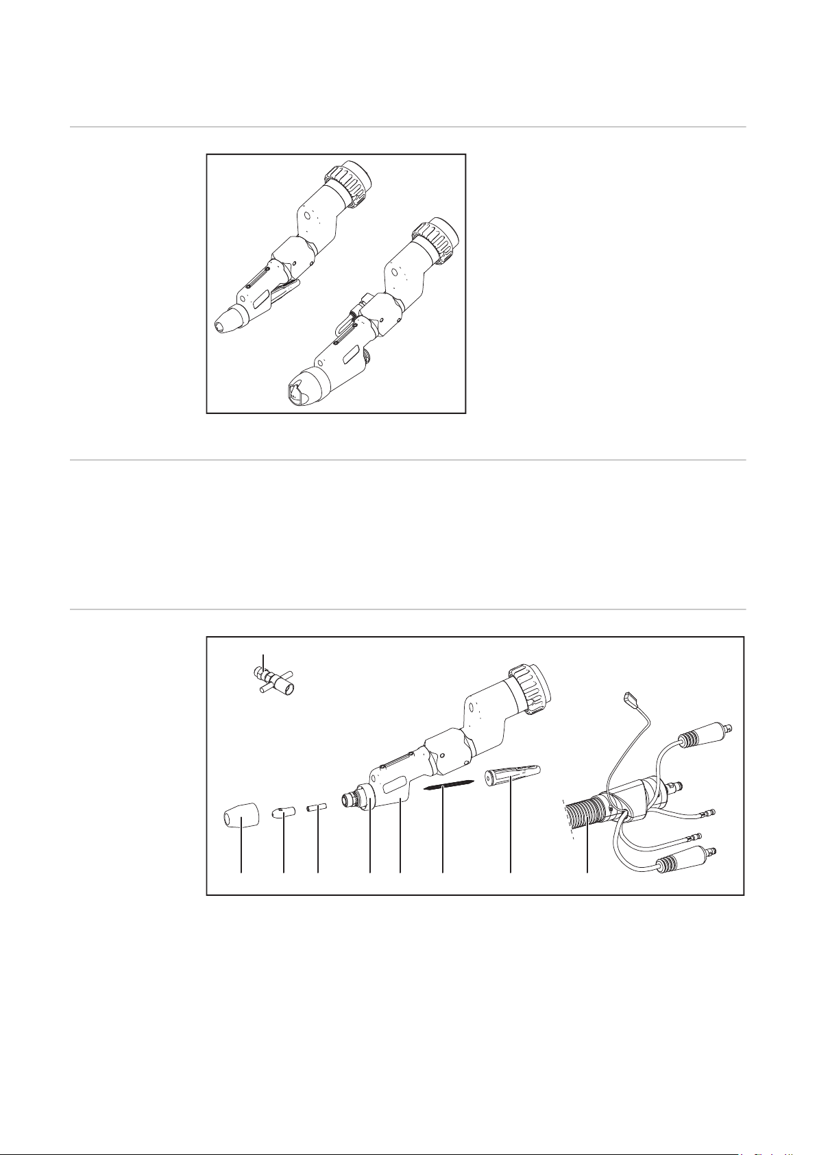
Gerätekonzept PTW 1500 / 3500 PAP
Einsatzgebiete Die Roboter-Schweißbrenner kommen bei folgenden Anwendungen zum Einsatz, z.B.:
- im Rohrleitungs- und Apparatebau
- im Behälterbau
- bei höchsten Qualitätsanforderungen
- bei Sonderwerkstoffen (z.B.: Titan, Nickelbasis-Legierungen)
- Automobil- und Automobilzulieferindustrie
Die wassergekühlten Plasma RoboterSchweißbrenner PTW 1500 und PTW
3500 dienen zum Plasmaschweißen und
zum Plasmalöten.
Die Schweißbrenner haben serienmäßig
einen Fronius F++ Anschluss. Für den
Betrieb an einem handelsüblichen
Plasma-Gerät stehen verschiedene Adapter zur Verfügung. Jeder Schweißbrenner
kann mit einer geschobenen KD oder
einer Schleppgasdüse ausgestattet werden. Das Schlauchpaket kann auch für
bestimmte WIG-Schweißbrenner verwendet werden
Lieferumfang
Lieferumfang PTW 1500 PAP
(1) Keramische Schutz-Gasdüse
(2) Plasmadüse 2,5 mm
(3) Keramik-Zentrierrohr 2,5 mm
(4) Isolierring
(5) Brennerkörper PTW
(6) Wolframelektrode 2,4 mm
(7) Brennerkappe mittel
(8) Schlauchpaket mit integriertem
Drahtförderschlauch
(9) Einstell-Lehre
4
Page 5

(11)
(1) (4) (6) (7) (8) (9) (10)
(2)
(3)
(5)
Lieferumfang PTW 3500 PAP
DE
Optionen PTW
1500 PAP
Optionen PTW
3500 PAP
(1) Keramische Schutz-Gasdüse
(2) Federring
(3) Isolierring
(4) Plasmadüse 3,2 mm
(5) Keramik-Zentrierrohr 3,2 mm
(6) Brennerkörper PTW
(7) Wolframelektrode 4,8 mm
(8) Spannhülse 4,8 mm
(9) Brennerkappe kurz
(10) Schlauchpaket mit integriertem
Drahtförderschlauch
(11) Einstell-Lehre
- Kaltdrahtzuführung (Push-System): Robacta KD Plasma / WIG PAP
- Plasmadüse (siehe Ersatzteilliste)
- Keramik-Zentrierrohr (siehe Ersatzteilliste)
- Spannhülse (siehe Ersatzteilliste)
- Schleppgasdüse 50 / 100 mm
- Einstell-Lehre 1,5 - 2 mm
- Brennerkappen
- Kaltdrahtzuführung (Push-System): Robacta KD Plasma / WIG PAP
- Plasmadüse (siehe Ersatzteilliste)
- Plasmadüse konisch
- Keramik-Zentrierrohr (siehe Ersatzteilliste)
- Spannhülse (siehe Ersatzteilliste)
- Schleppgasdüse 50 / 100 mm / large
- Gasdüsen (siehe Ersatzteilliste)
- Gaslinse (wassergekühlt)
- Brennerkappen
- Einstell-Lehre 2 - 3 mm
5
Page 6

Schweißbrenner montieren
2
3
1
1
2
Sicherheit
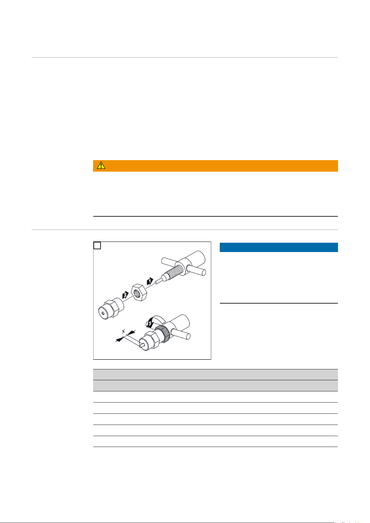
PTW montieren
WARNUNG!
Fehlerhaft durchgeführte Arbeiten können schwerwiegende Personen- und
Sachschäden verursachen.
Die Anschlussarbeiten dürfen nur von geschultem Fachpersonal unter Berücksichti-
▶
gung der gültigen Sicherheitsbestimmungen durchgeführt werden!
Sicherheitsvorschriften in der Bedienungsanleitung beachten!
▶
WARNUNG!
Ein elektrischer Schlag kann tödlich sein.
Vor Arbeiten am Schweißbrenner:
Netzschalter von Stromquelle und Plasmagerät in Stellung „0“ schalten
▶
Stromquelle und Plasmagerät vom Netz trennen
▶
ein verständliches Warnschild gegen Wiedereinschalten anbringen
▶
1
2
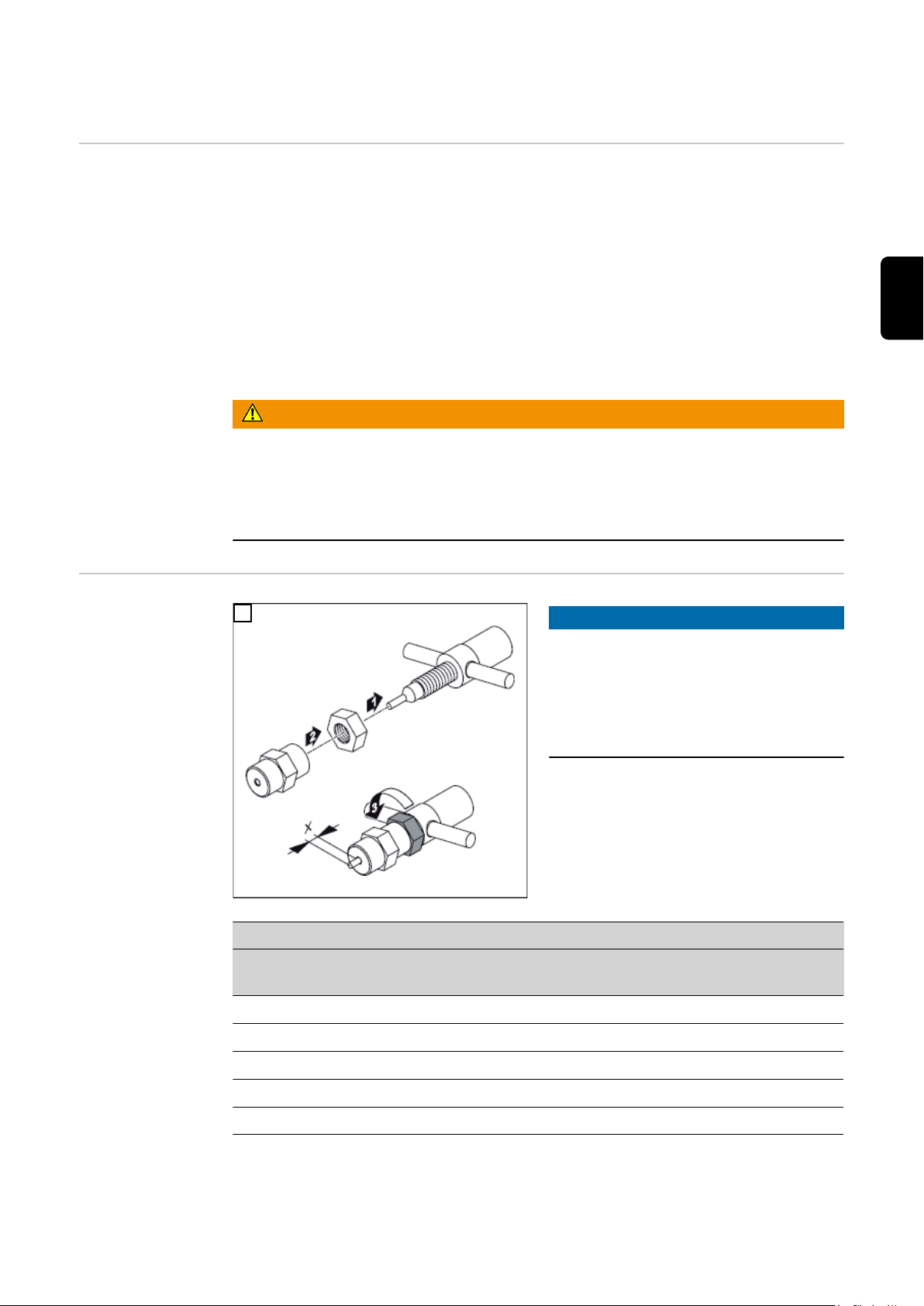
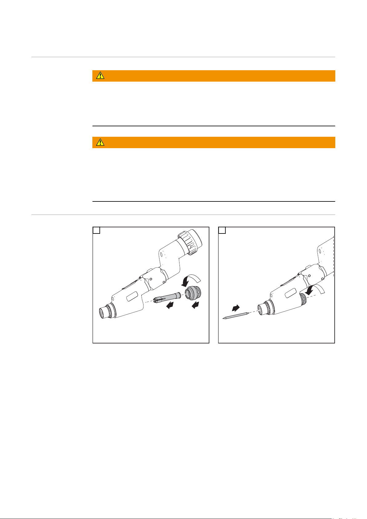
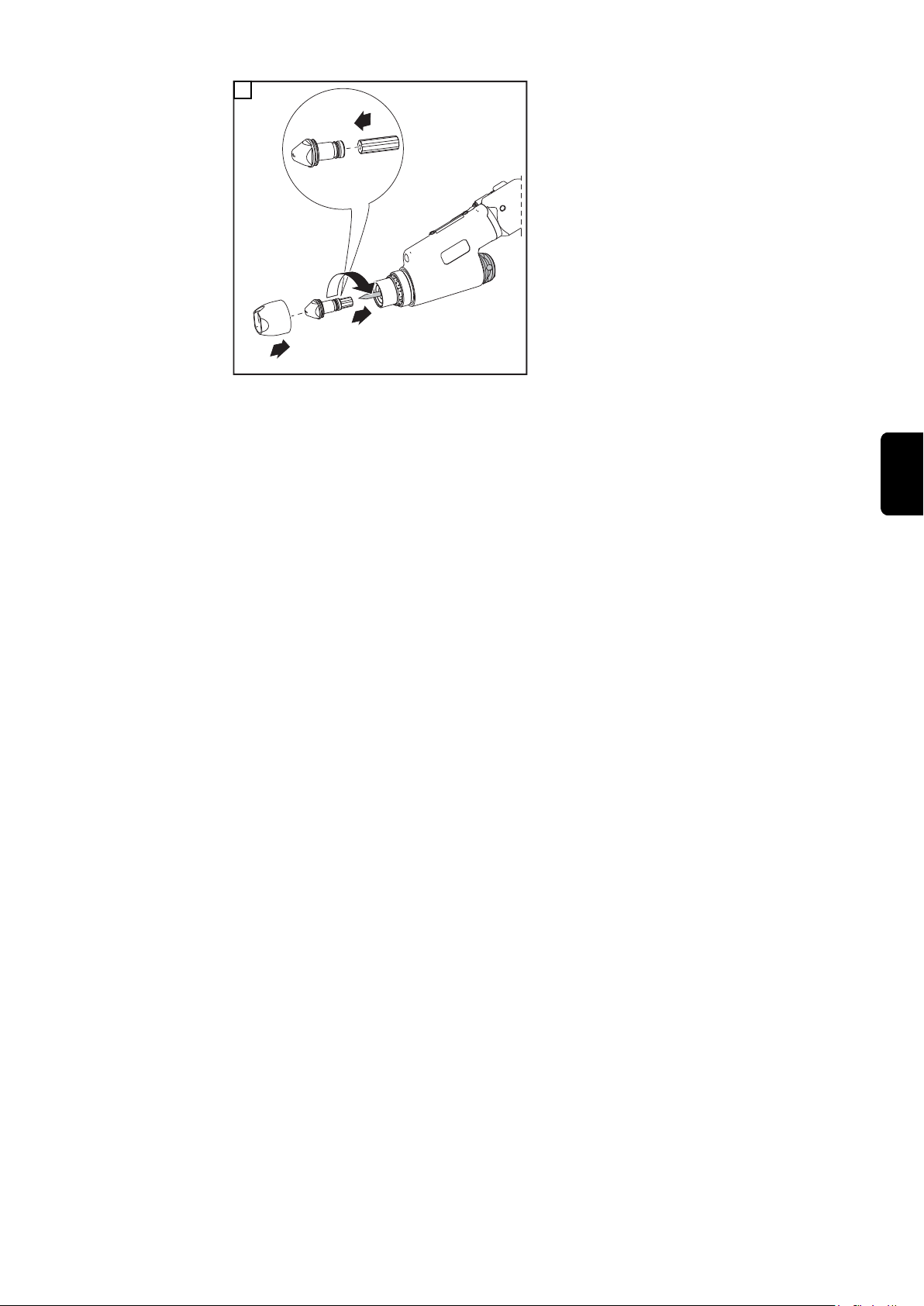
WICHTIG! Die Wolframelektrode so einsetzen, dass die Spitze ca.10 mm aus dem Bren-
nerkörper ragt. Brennerkappe leicht anziehen, die Wolframelektrode sollte im Brennerkörper noch verschiebbar sein.
6
Page 7

1
2
4
3
*
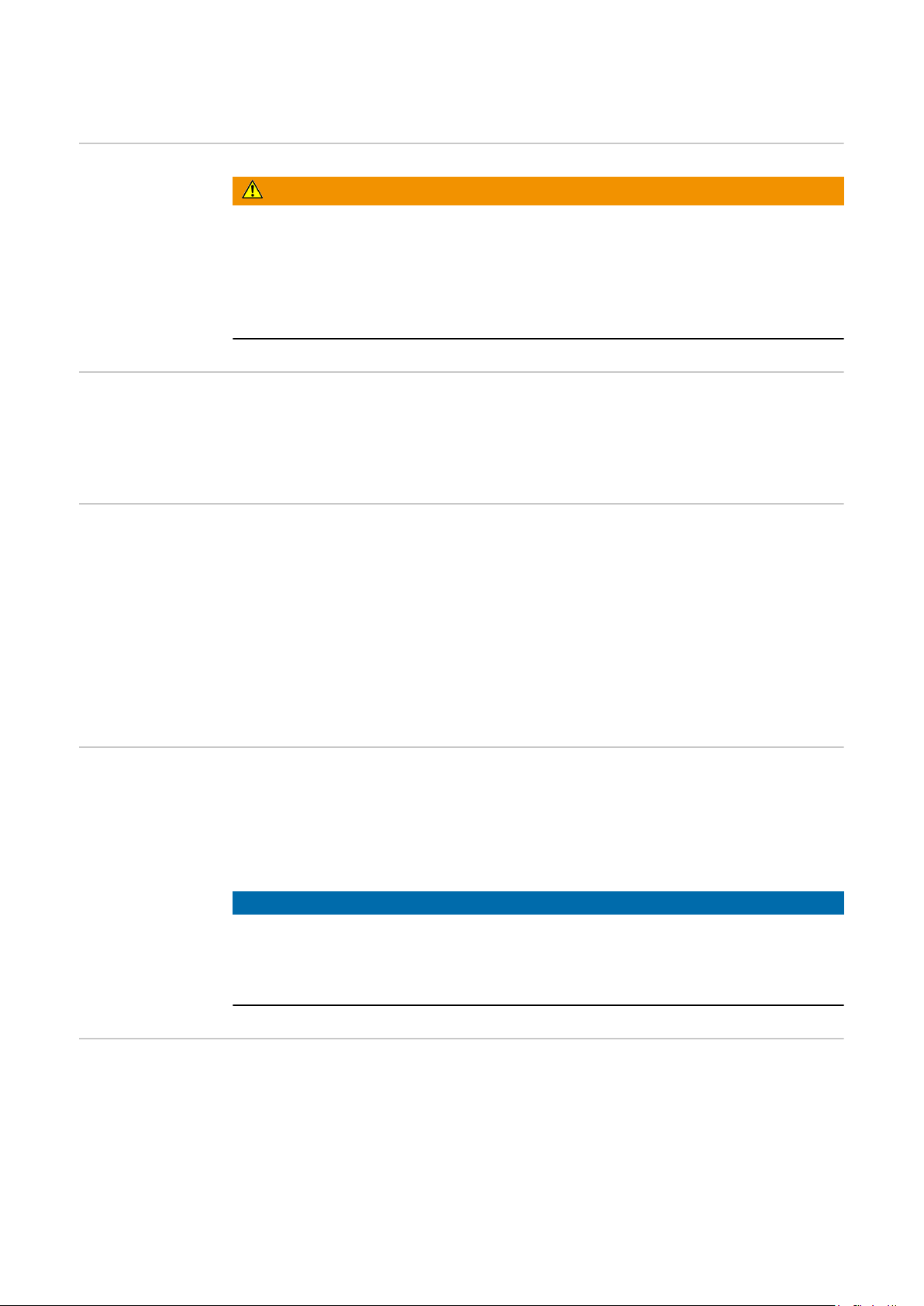
* PTW 1500: 3 Nm
3
WICHTIG! Auf korrekte Einstellung der Wolframelektrode achten (siehe Kapitel „ Wolf-
ramelektrode einstellen“)
DE
7
Page 8
Wolframelektrode einstellen
Allgemeines Unter Belastungsgrenzen versteht man den maximal möglichen Schweißstrom
- bei einer bestimmten Plasmadüse,
- bei einer bestimmten Plasmagas-Menge,
- bei einer bestimmten Position der Wolframelektrode
- in Abhängigkeit der Kühlleistung des Kühlgerätes.
Die Position der Wolframelektrode ist neben der eingestellten Plasmagas-Menge ausschlaggebend für die Belastungsgrenzen.
Der Einstell-Vorgang für die Wolframelektrode zum Plasma-Schweißen / Plasma-Löten
wird im folgenden Abschnitt beschrieben.
WARNUNG!
Fehlerhaft durchgeführte Arbeiten können schwerwiegende Personen und
Sachschäden verursachen.
Nachfolgend beschriebene Tätigkeiten dürfen nur von geschultem Fachpersonal
▶
durchgeführt werden!
Beachten Sie die Sicherheitsvorschriften!
▶
Einstell-Lehre
justieren
1
PTW 1500
Ø Plasmadüse „x“ Einstell-Lehre
1,0 mm - 1,5 mm 1,5 mm Ø 1,5 - 2 mm
2,0 mm 2,0 mm Ø 1,5 - 2 mm
HINWEIS!
Die Standard-Einstellung für das Maß
„x“ an der jeweiligen Einstell-Lehre ist
abhängig vom Durchmesser der Plasmadüse.
Standard-Einstellung für das Maß „x“
gemäß folgender Tabelle einstellen:
2,5 mm 2,5 mm Ø 2,5 - 3 mm
3,0 mm 2,5 mm Ø 2,5 - 3 mm
8
Page 9

PTW 3500
1
1
1
Ø Plasmadüse „x“ Einstell-Lehre
2,0 mm 2,0 mm Ø 1,5 - 2 mm
2,5 mm 2,0 mm Ø 1,5 - 2 mm
3,2 mm 2,5 mm Ø 2,5 - 3 mm
3,5 mm 3,0 mm Ø 2,5 - 3 mm
4,0 mm 3,0 mm Ø 2,5 - 3 mm
5,0 mm 4,0 mm Ø 2,5 - 3 mm
DE
Wolframelektrode
einstellen
1
3
2
4
9
Page 10

Fehlerdiagnose, Fehlerbehebung
Sicherheit
Fehlerdiagnose,
Fehlerbehebung
WARNUNG!
Ein elektrischer Schlag kann tödlich sein.
Vor Arbeiten am Schweißbrenner:
Netzschalter von Stromquelle und Plasmagerät in Stellung „0“ schalten
▶
Stromquelle und Plasmagerät vom Netz trennen
▶
ein verständliches Warnschild gegen Wiedereinschalten anbringen
▶
Pilot-Lichtbogen zündet nicht
Ursache:
Behebung:
Ursache:
Behebung:
Ursache:
Behebung:
Kupfer-Tropfen auf der Plasmadüse nach kurzer Schweißzeit
Tropfenbildung auf der Plasmadüse ist ein Zeichen für eine starke Beschädigung der
Plasmadüse: die Plasmadüse wird auf Grund zu hoher Temperatur aufgeschmolzen und
läuft aus.
Wolframelektrode fehlt
Wolframelektrode einsetzen
Zu großer Abstand zwischen Plasmadüse und Wolframelektrode
Wolframelektrode richtig positionieren
Kein oder zu geringer Abstand zwischen Plasmadüse und Wolframelektrode
(Kurzschluss zwischen Plasmadüse und Wolframelektrode)
Wolframelektrode richtig positionieren
Ursache:
Behebung:
Hoher Plasmadüsen-Verschleiß
Ursache:
Behebung:
HF wird auf Roboter abgeleitet
Ursache:
Behebung:
zu hohe Belastungswerte
Strom und Plasmagas-Menge kontrollieren, Plasmadüse wechseln, Belas-
tung reduzieren
schlechte Kühlung
Strom und Plasmagas-Menge kontrollieren, Kühlkreislauf kontrollieren,
Plasmagas-Menge erhöhen, Verschleiß der Düsenanbindung prüfen
Elektrisch leitender Roboterflansch montiert
Kunststoff-Roboterflansch montieren
10
Page 11

Pflege, Wartung und Entsorgung
DE
Sicherheit
Ein elektrischer Schlag kann tödlich sein.
Vor Arbeiten am Schweißbrenner:
▶
▶
▶
Allgemeines Regelmäßige und vorbeugende Wartung des Schweißbrenners sind wesentliche Fakto-
ren für einen störungsfreien Betrieb. Der Schweißbrenner ist hohen Temperaturen ausgesetzt. Daher benötigt der Schweißbrenner eine häufigere Wartung als andere Komponenten einer Schweißanlage.
Bei jeder Inbetriebnahme
- Plasmabrenner, Brennerschlauchpaket und Stromanschlüsse auf Beschädigung
- Gas- und Wasseranschlüsse auf Dichtheit prüfen
- Kühlgerät zur Kühlung des Plasmabrenners auf einwandfreie Funktion überprüfen,
- Plasmabrenner-Verschleißteile auf einwandfreien Zustand prüfen, Verschleißteile
- festen Sitz der Überwurfmutter prüfen (Kuppelstelle Schlauchpaket - Plasmabren-
WARNUNG!
Netzschalter von Stromquelle und Plasmagerät in Stellung „0“ schalten
Stromquelle und Plasmagerät vom Netz trennen
ein verständliches Warnschild gegen Wiedereinschalten anbringen
prüfen
Wasser Rückflussmenge im Kühlmittelbehälter überwachen, ggf. Kühlgerät entlüften
vor dem Einbau reinigen
ner)
Monatliche Wartungstätigkeiten
Entsorgung Die Entsorgung nur gemäß den geltenden nationalen und regionalen Bestimmungen
- Falls vorhanden, Filter im Kühlkreislauf auf Verunreinigung prüfen
- Kühlmittel auf Reinheit prüfen; bei grober Verunreinigung Kühlmittel austauschen
und Plasmabrenner über Kühlmittel-Vorlauf und Kühlmittelrücklauf mehrmals
durchspülen
HINWEIS!
Ablagerungen im Inneren des Plasmabrenners können Hochfrequenz-Überschläge
verursachen und somit den Plasmabrenner beschädigen.
Plasmabrenner zerlegen und auf Ablagerungen / Verunreinigungen prüfen
▶
durchführen.
11
Page 12
Technische Daten
PTW 1500, PTW
3500
PTW 1500 PTW 3500
Leistungsbereich 3 - 150 A 3 - 350 A
Maximalwert bei 100 % Einschaltdauer 150 A 350 A
Strom Pilotlichtbogen 10 A 30 A
Spannungsbemessung (V-Peak) 141 V 141 V
Plasmagas / Schutzgas (laut EN 439) Argon Argon
Kühlsystem
Kühlmittel
Kühlleistung 1000 W ***) 1900 W ***)
Kühlmitteldruck min. 3,0 bar
Kühlmitteldruck max. 5,5 bar
Kühlmittel-Mindestdurchfluss 1,0 l / min 1,0 l / min
*) Flüssigkeitskühlung
**) Original Fronius-Kühlmittel
***) Geringste Kühlleistung laut Norm IEC 60974-2
*)
**)
43,50 psi.
79,74 psi.
*)
**)
3,0 bar
43,50 psi.
5,5 bar
79,74 psi.
Belastungsgrenzen in Abhängigkeit von der Plasmagas-Menge
Das Produkt entspricht den Anforderungen laut Norm IEC 60974-7
Zum Plasmaschweißen müssen die eingestellten Werte für Plasmagas-Menge und maximalen Schweißstrom innerhalb der angegebenen Grenzwerte liegen. Ein Unter- oder
Überschreiten dieser Grenzwerte bringt eine Veränderung der Plasmaeigenschaften mit
sich z.B.:
- Geringere Plasmagas-Menge -> „weicher“ Plasmastrahl
- Hohe Plasmagas-Menge -> „harter“ Plasmastrahl („Plasma-Schneiden“)
HINWEIS!
Grenzwerte für Plasmagas-Werte und max. Schweißstrom während des Betriebes
nicht unterschreiten.
HINWEIS!
Die Kühlmittel-Mindestdurchflussmenge beträgt 1 l / min
Tabelle gilt nur für PTW 1500
ø Plasmadüse Plasmagas-Menge * max. Schweißstrom
12
1,5 mm min. 0,30 l / min
max. 0,80 l / min
2,0 mm min. 0,35 l / min
max. 1,00 l / min
60 A
100 A
80 A
120 A
Page 13
ø Plasmadüse Plasmagas-Menge * max. Schweißstrom
2,5 mm min. 0,45 l / min
max. 1,20 l / min
3,0 mm min. 0,55 l / min
max. 1,30 l / min
Tabelle gilt nur für PTW 3500 in Verbindung mit einem FK 9000 Kühlgerät
ø Plasmadüse Plasmagas-Menge * max. Schweißstrom
2,0 mm min. 1,0 l / min 170 A
2,5 mm min. 1,0 l / min 190 A
3,2 mm min. 1,0 l / min 210 A
3,5 mm min. 1,0 l / min 225 A
4,0 mm min. 1,0 l / min 250 A
Tabelle gilt nur für PTW 3500 in Verbindung mit einem CHILLY 15 Kühlgerät
ø Plasmadüse Plasmagas-Menge * max. Schweißstrom
2,0 mm min. 1,0 l / min 225 A
2,5 mm min. 1,0 l / min 250 A
3,2 mm min. 1,0 l / min 275 A
110 A
145 A
130 A
150 A
DE
3,5 mm min. 2,0 l / min 300 A
4,0 mm min. 2,0 l / min 350 A
* Korrekturfaktor vom Plasmamodul muss auf Automatik gestellt sein
Minimale Plasmagas-Menge:
Gasmenge, bei der der Schweiß-Lichtbogen gerade noch stabil brennt.
HINWEIS!
Schweißungen mit minimaler Plasmagas-Menge stellen eine sehr hohe Belastung
für die Plasmadüse dar und sollten vermieden werden.
Maximaler Schweißstrom:
Schweißstrom, der bei einer bestimmten Plasmadüse, bei Standard-Einstellung der
Wolframelektrode, bei minimaler Plasmagas-Menge und abhängig vom Kühlgerät
zulässig ist.
Beispiel PTW 1500:
Bei einer Plasmadüse mit einem Durchmesser von 2,0 mm, einer eingestellten MindestPlasmagas-Menge von 0,25 l/min ist bei Standardeinstellung der Wolframelektrode ein
maximaler Schweißstrom von 80 A zulässig.
HINWEIS!
Als Plasmagas reines Argon verwenden! Nur reines Argon gewährleistet das Erreichen der oben angeführten Grenzwerte.
13
Page 14

14
Page 15

Contents
General 16
Device concept 16
Application areas 16
Scope of supply 16
PTW 1500 PAP options 17
PTW 3500 PAP options 17
Fitting the welding torch 18
Safety 18
Installing the PTW 18
Adjusting the tungsten electrode 20
General 20
Calibrating the adjusting gauge 20
Adjusting the tungsten electrode 21
Troubleshooting 22
Safety 22
Troubleshooting 22
Care, maintenance and disposal 23
Safety 23
General 23
At every start-up 23
Monthly 23
Disposal 23
Technical data 24
PTW 1500, PTW 3500 24
Loading limits dependent on the plasma gas flow rate 24
EN
15
Page 16

General
(9)
(1) (2) (3) (5)(4) (6) (7) (8)
Device concept
PTW 1500 / 3500 PAP device concept
Application areas The robot welding torches are used in, e.g.:
- Pipeline and equipment construction
- Container construction
- Applications requiring the highest quality standards
- Applications using special materials (e.g. titanium, nickel-based alloys)
- The automobile and the automotive component supply industries
The PTW 1500 and PTW 3500 water-cooled plasma robot welding torches are used
for plasma welding and plasma brazing.
The welding torches have a Fronius F++
connection as standard. Various adapters
are available to enable the torches to be
operated with any standard plasma
device. Each torch can be equipped with a
pushed wire-feed unit or a drag gas
nozzle. The hosepack can also be used
with certain TIG welding torches.
Scope of supply
PTW 1500 PAP scope of supply
(1) Ceramic protective gas nozzle
(2) Plasma nozzle 2.5 mm
(3) Ceramic centring tube 2.5 mm
(4) Insulation ring
(5) PTW torch body
(6) Tungsten electrode 2.4 mm
(7) Torch cap, medium
(8) Hosepack with integrated wire-
feed hose
(9) Adjusting gauge
16
Page 17

(11)
(1) (4) (6) (7) (8) (9) (10)
(2)
(3)
(5)
PTW 3500 PAP scope of supply
EN
PTW 1500 PAP
options
PTW 3500 PAP
options
(1) Ceramic protective gas nozzle
(2) Lock washer
(3) Insulation ring
(4) Plasma nozzle 3.2 mm
(5) Ceramic centring tube 3.2 mm
(6) PTW torch body
(7) Tungsten electrode 4.8 mm
(8) Clamping sleeve 4.8 mm
(9) Torch cap, short
(10) Hosepack with integrated wire-
feed hose
(11) Adjusting gauge
- Cold wire feeder (push system): Robacta KD Plasma / TIG PAP
- Plasma nozzle (see spare parts list)
- Ceramic centring tube (see spare parts list)
- Fixing sleeve (see spare parts list)
- Drag gas nozzle 50 / 100 mm
- Adjusting gauge 1.5 - 2 mm
- Torch caps
- Cold wire feeder (push system): Robacta KD Plasma / TIG PAP
- Plasma nozzle (see spare parts list)
- Conical plasma nozzle
- Ceramic centring tube (see spare parts list)
- Fixing sleeve (see spare parts list)
- Drag gas nozzle 50 / 100 mm / large
- Gas nozzles (see spare parts list)
- Gas lens (water-cooled)
- Torch caps
- Adjusting gauge 2 - 3 mm
17
Page 18

Fitting the welding torch
2
3
1
1
2
Safety
Installing the
PTW
WARNING!
Work that is carried out incorrectly can cause serious injury and damage.
All connections must be made by trained and qualified personnel in compliance with
▶
the relevant safety regulations.
Note the safety rules in the operating instructions.
▶
WARNING!
An electric shock can be fatal.
Before carrying out any work on the welding torch:
Turn the mains switches of the power source and plasma device to the "0" position
▶
Disconnect the power source and plasma device from the mains
▶
Put up an easy-to-understand warning sign to stop anybody inadvertently switching
▶
them back on again
1
2
IMPORTANT! Insert the tungsten electrode so that the tip protrudes approx. 10 mm out
of the torch body. Slightly tighten the torch cap so that the tungsten electrode can still
move inside the torch body.
18
Page 19

1
2
4
3
*
* PTW 1500: 3 Nm
3
IMPORTANT! Check that the tungsten electrode is adjusted correctly (see the "Adjusting
the tungsten electrode" chapter)
EN
19
Page 20

Adjusting the tungsten electrode
General By loading limits we mean the maximum possible welding current
- for a particular plasma nozzle,
- for a particular plasma gas flow rate,
- for a particular tungsten electrode position
- depending on the cooling power of the cooling unit.
Apart from the specified plasma gas flow rate, the position of the tungsten electrode
plays a crucial role in determining the loading limits.
The setting process for the tungsten electrode for plasma welding / plasma brazing is
described in the following section.
WARNING!
Work that is carried out incorrectly can cause serious injury and damage.
The following activities may only be carried out by trained and qualified personnel.
▶
Observe the safety rules.
▶
Calibrating the
adjusting gauge
1
PTW 1500
Plasma nozzle dia. "x" Adjusting gauge
1.0 mm - -
1.5 mm 1.5 mm dia. 1.5 - 2 mm
2.0 mm 2.0 mm dia. 1.5 - 2 mm
NOTE!
The standard setting for measurement
"x" on the adjusting gauge depends on
the diameter of the plasma nozzle.
Set the standard setting for measurement
"x" according to the following table:
20
2.5 mm 2.5 mm dia. 2.5 - 3 mm
3.0 mm 2.5 mm dia. 2.5 - 3 mm
Page 21

PTW 3500
1
1
1
Plasma nozzle dia. "x" Adjusting gauge
2.0 mm 2.0 mm dia. 1.5 - 2 mm
2.5 mm 2.0 mm dia. 1.5 - 2 mm
3.2 mm 2.5 mm dia. 2.5 - 3 mm
3.5 mm 3.0 mm dia. 2.5 - 3 mm
4.0 mm 3.0 mm dia. 2.5 - 3 mm
5.0 mm 4.0 mm dia. 2.5 - 3 mm
EN
Adjusting the
tungsten electrode
1
3
2
4
21
Page 22

Troubleshooting
Safety
Troubleshooting
WARNING!
An electric shock can be fatal.
Before carrying out any work on the welding torch:
Turn the mains switches of the power source and plasma device to the "0" position
▶
Disconnect the power source and plasma device from the mains
▶
Put up an easy-to-understand warning sign to stop anybody inadvertently switching
▶
them back on again
Pilot arc not igniting
Cause:
Remedy:
Cause:
Remedy:
Cause:
Remedy:
Tungsten electrode missing
Insert tungsten electrode
Plasma nozzle and tungsten electrode too far apart
Position tungsten electrode correctly
Plasma nozzle and tungsten electrode touching or too close (short circuit
between plasma nozzle and tungsten electrode)
Position tungsten electrode correctly
Copper droplets on the plasma nozzle after a short welding time
Droplet formation on the plasma nozzle is a sign that the plasma nozzle has been badly
damaged: the plasma nozzle has melted due to high temperatures and is leaking.
Cause:
Remedy:
Excessive plasma nozzle wear
Cause:
Remedy:
HF is conducted to robot
Cause:
Remedy:
Loading values too high
Check the current and plasma gas flow rate, change the plasma nozzle,
reduce the load
Insufficient cooling
Check the current and plasma gas flow rate, check the cooling circuit, incre-
ase the plasma gas flow rate, check for wear on the nozzle connection
Electrically-conductive robot flange fitted
Fit plastic robot flange
22
Page 23

Care, maintenance and disposal
Safety
An electric shock can be fatal.
Before carrying out any work on the welding torch:
▶
▶
▶
General Regular preventive maintenance of the welding torch is essential for problem-free opera-
tion. The welding torch is subjected to high temperatures. It therefore requires more frequent maintenance than other components in the welding system.
At every start-up - Check plasma torch, torch hosepack and current connections for signs of damage
- Check gas and water connections for leaks
- Check that the cooling unit used for cooling the plasma torch is functioning properly,
- Check that the wearing parts for the plasma torch are in perfect condition, clean
- Check that the union nut is secure (hosepack - plasma torch interface)
WARNING!
Turn the mains switches of the power source and plasma device to the "0" position
Disconnect the power source and plasma device from the mains
Put up an easy-to-understand warning sign to stop anybody inadvertently switching
them back on again
monitor the water return level in the coolant container, bleed the cooling unit if
necessary
wearing parts before fitting them
EN
Monthly - If applicable, check the filter in the cooling circuit for contamination
- Check that coolant is pure; if there are any impurities, replace the coolant and rinse
the plasma torch thoroughly several times by letting coolant flow into it and back out
again
NOTE!
Deposits inside the plasma torch can cause high frequency arc-overs, thereby
damaging the plasma torch
Dismantle the plasma torch and check for deposits/contamination
▶
Disposal Dispose of in accordance with the applicable national and local regulations.
23
Page 24

Technical data
PTW 1500, PTW
3500
PTW 1500 PTW 3500
Power range 3 - 150 A 3 - 350 A
Maximum value at 100 % duty cycle 150 A 350 A
Pilot arc current 10 A 30 A
Voltage measurement (V-Peak) 141 V 141 V
Plasma gas/shielding gas (according to EN 439) Argon Argon
Cooling system
coolant
Cooling power 1000 W ***) 1900 W ***)
Min. coolant pressure 3.0 bar
Max. coolant pressure 5.5 bar
Minimum coolant flow rate 1.0 l/min 1.0 l/min
*) Liquid cooling
**) Original Fronius coolant
***) Lowest cooling power according to standard IEC 60974-2
*)
**)
43.50 psi.
79.74 psi.
*)
**)
3.0 bar
43.50 psi.
5.5 bar
79.74 psi.
Loading limits
dependent on the
plasma gas flow
rate
The product conforms to the requirements of standard IEC 60974-7
For plasma welding, the values for the plasma gas flow rate and maximum welding current must lie within the set limit values. An upper or lower exceed of these limit values
can change the plasma properties, e.g.:
- lower rate of plasma gas flow -> "soft" plasma jet
- high rate of plasma gas flow -> "hard" plasma jet ("plasma cutting")
NOTE!
Do not exceed the lower limit values set for plasma gas values and max. welding
current during operation.
NOTE!
The minimum coolant flow rate is 1 l/min
This table is only valid for the PTW 1500
Plasma nozzle dia. Plasma gas flow rate * Max. welding current
1.5 mm Min. 0.30 l/min
Max. 0.80 l/min
60 A
100 A
24
2.0 mm Min. 0.35 l/min
Max. 1.00 l/min
2.5 mm Min. 0.45 l/min
Max. 1.20 l/min
80 A
120 A
110 A
145 A
Page 25

Plasma nozzle dia. Plasma gas flow rate * Max. welding current
3.0 mm Min. 0.55 l/min
Max. 1.30 l/min
This table is only valid for the PTW 3500 in conjunction with an FK 9000 cooling
unit
Plasma nozzle dia. Plasma gas flow rate * Max. welding current
2.0 mm Min. 1.0 l/min 170 A
2.5 mm Min. 1.0 l/min 190 A
3.2 mm Min. 1.0 l/min 210 A
3.5 mm Min. 1.0 l/min 225 A
4.0 mm Min. 1.0 l/min 250 A
This table is only valid for the PTW 3500 in conjunction with a CHILLY 15 cooling
unit
Plasma nozzle dia. Plasma gas flow rate * Max. welding current
2.0 mm Min. 1.0 l/min 225 A
2.5 mm Min. 1.0 l/min 250 A
3.2 mm Min. 1.0 l/min 275 A
3.5 mm Min. 2.0 l/min 300 A
130 A
150 A
EN
4.0 mm Min. 2.0 l/min 350 A
* Correction factor of the plasma module must be on Automatic
Minimum rate of plasma gas flow:
gas flow rate at which the welding arc just remains stable.
NOTE!
Welding using a minimum plasma gas flow places a severe load on the plasma
nozzle and should be avoided.
Maximum welding current:
welding current that is permitted for a particular plasma nozzle, with the standard tungsten electrode setting, the minimum plasma gas flow rate and depending on the cooling
unit.
Example PTW 1500:
in the case of a plasma nozzle with a diameter of 2.0 mm and a specified minimum
plasma gas flow rate of 0.25 l/min, a maximum welding current of 80 A is permitted for
the standard tungsten electrode setting.
NOTE!
Use pure argon as the plasma gas.
The limit values listed above can only be obtained using pure argon.
25
Page 26

26
Page 27

Tabla de contenido
Generalidades 28
Diseño de los equipos 28
Campos de aplicación 28
Volumen de suministro 28
Opciones PTW 1500 PAP 29
Opciones PTW 3500 PAP 30
Montar la antorcha 31
Seguridad 31
Montar la PTW 31
Ajustar el electrodo de tungsteno 33
Generalidades 33
Ajustar el calibre de ajuste 33
Ajustar el electrodo de tungsteno 34
Diagnóstico de errores, solución de errores 35
Seguridad 35
Diagnóstico de errores, solución de errores 35
Cuidado, mantenimiento y eliminación 36
Seguridad 36
Generalidades 36
Con cada puesta en servicio 36
Mensualmente 36
Eliminación 36
Datos técnicos 37
PTW 1500, PTW 3500 37
Límites de carga en función de la cantidad de gas plasma 37
ES
27
Page 28

Generalidades
(9)
(1) (2) (3) (5)(4) (6) (7) (8)
Diseño de los
equipos
Campos de aplicación
Las antorchas de robot de soldadura con
chorro de plasma refrigeradas por agua
PTW 1500 y PTW 3500 sirven para la
soldadura con chorro de plasma y la soldadura indirecta con chorro de plasma.
Estas antorchas tienen de serie una conexión F++ de Fronius. Hay disponibles
diferentes adaptadores para equipos de
plasma de uso convencional. Cada antorcha puede equiparse con un KD de
empuje o una tobera de arrastre para gas.
También es posible utilizar el paquete de
mangueras para determinadas antorchas
TIG.
Diseño de los equipos PTW 1500 / 3500 PAP
Las antorchas de robot se utilizan para las siguientes aplicaciones, por ejemplo:
- Construcción de tuberías y aparatos
- Construcción de depósitos
- Cuando se requiere una calidad máxima
- Materiales especiales (por ejemplo: titanio, aleaciones en base a níquel)
- Industria automovilística y proveedores de automoción
Volumen de
suministro
Volumen de suministro PTW 1500 PAP
28
Page 29

(1) Tobera de gas protector de
(11)
(1) (4) (6) (7) (8) (9) (10)
(2)
(3)
(5)
cerámica
(2) Inyector de plasma 2,5 mm
(3) Tubo de centraje de cerámica
2,5 mm
(4) Anillo aislante
(5) Cuerpo de antorcha PTW
(6) Electrodo de tungsteno 2,4 mm
(7) Caperuza de antorcha media
(8) Paquete de mangueras con
manguera de transporte de hilo
integrada
(9) Calibre de ajuste
ES
Opciones PTW
1500 PAP
Volumen de suministro PTW 3500 PAP
(1) Tobera de gas protector de
cerámica
(2) Anillo elástico
(3) Anillo aislante
(4) Inyector de plasma 3,2 mm
(5) Tubo de centraje de cerámica
3,2 mm
(7) Electrodo de tungsteno 4,8 mm
(8) Virola tensora 4,8 mm
(9) Caperuza de antorcha corta
(10) Paquete de mangueras con
manguera de transporte de hilo
integrada
(11) Calibre de ajuste
(6) Cuerpo de antorcha PTW
- Alimentación de hilo frío (sistema Push): Robacta KD para soldadura con chorro de
plasma / TIG PAP
- Inyector de plasma (ver la lista de repuestos)
- Tubo de centraje de cerámica (ver la lista de repuestos)
- Virola tensora (ver la lista de repuestos)
- Tobera de arrastre para gas 50 / 100 mm
- Calibre de ajuste 1,5 - 2 mm
- Caperuzas de antorcha
29
Page 30

Opciones PTW
3500 PAP
- Alimentación de hilo frío (sistema Push): Robacta KD para soldadura con chorro de
plasma / TIG PAP
- Inyector de plasma (ver la lista de repuestos)
- Inyector de plasma cónico
- Tubo de centraje de cerámica (ver la lista de repuestos)
- Virola tensora (ver la lista de repuestos)
- Tobera de arrastre para gas 50 / 100 mm / largo
- Toberas de gas (ver la lista de repuestos)
- Lente de gas (refrigerada por agua)
- Caperuzas de antorcha
- Calibre de ajuste 2 - 3 mm
30
Page 31

Montar la antorcha
2
3
1
1
2
Seguridad
Montar la PTW
¡PELIGRO!
Los trabajos realizados de forma defectuosa pueden causar graves daños personales y materiales.
¡Los trabajos de conexión sólo deben ser realizados por personal técnico debida-
▶
mente formado teniendo en cuenta las disposiciones de seguridad vigentes!
Se deben tener en cuenta las indicaciones de seguridad del manual de instruccio-
▶
nes.
¡PELIGRO!
Las descargas eléctricas pueden ser mortales.
Antes de realizar trabajos en la antorcha:
Poner el interruptor de red de la fuente de corriente y del equipo de plasma en la
▶
posición "O".
Separar la fuente de corriente y el equipo de plasma de la red.
▶
Colocar un rótulo de aviso claro y legible para impedir cualquier reconexión.
▶
1
2
ES
¡IMPORTANTE! Colocar el electrodo de tungsteno de tal modo que la punta sobresalga
unos 10 mm del cuerpo de antorcha.
Apretar ligeramente la caperuza de antorcha, ya que aún debería poder desplazarse el
electrodo de tungsteno en el cuerpo de antorcha.
31
Page 32

1
2
4
3
*
* PTW 1500: 3 Nm
3
¡IMPORTANTE! Prestar atención al ajuste correcto del electrodo de tungsteno (ver el
capítulo "Ajustar el electrodo de tungsteno").
32
Page 33
Ajustar el electrodo de tungsteno
Generalidades Los límites de carga corresponden a la máxima corriente de soldadura
- en un determinado inyector de plasma.
- con una determinada cantidad de gas plasma.
- en una determinada posición del electrodo de tungsteno.
- en función de la potencia de refrigeración de la unidad de refrigeración.
Ajustar el calibre
de ajuste
Además de la cantidad de gas plasma ajustada, la posición del electrodo de tungsteno
resulta determinante para los límites de carga.
El siguiente apartado describe el proceso de ajuste para el electrodo de tungsteno en la
soldadura con chorro de plasma/soldadura indirecta con chorro de plasma.
¡PELIGRO!
Los trabajos realizados de forma defectuosa pueden causar graves daños personales y materiales.
¡Las actividades descritas a continuación solo deben ser realizadas por personal
▶
técnico debidamente instruido!
¡Tener en cuenta las indicaciones de seguridad!
▶
1
¡OBSERVACIÓN!
El ajuste estándar para la medida "x"
en el correspondiente calibre de ajuste
varía en función del diámetro del inyector de plasma.
Realizar el ajuste estándar pata la medida
"x" según la siguiente tabla:
ES
PTW 1500
Ø del inyector de
plasma
1,0 mm - 1,5 mm 1,5 mm Ø 1,5 - 2 mm
2,0 mm 2,0 mm Ø 1,5 - 2 mm
2,5 mm 2,5 mm Ø 2,5 - 3 mm
3,0 mm 2,5 mm Ø 2,5 - 3 mm
"x" Calibre de ajuste
33
Page 34

PTW 3500
1
1
1
Ajustar el electrodo de tungsteno
Ø del inyector de
"x" Calibre de ajuste
plasma
2,0 mm 2,0 mm Ø 1,5 - 2 mm
2,5 mm 2,0 mm Ø 1,5 - 2 mm
3,2 mm 2,5 mm Ø 2,5 - 3 mm
3,5 mm 3,0 mm Ø 2,5 - 3 mm
4,0 mm 3,0 mm Ø 2,5 - 3 mm
5,0 mm 4,0 mm Ø 2,5 - 3 mm
1
2
3
4
34
Page 35

Diagnóstico de errores, solución de errores
Seguridad
Diagnóstico de
errores, solución
de errores
¡PELIGRO!
Las descargas eléctricas pueden ser mortales.
Antes de realizar trabajos en la antorcha:
Poner el interruptor de red de la fuente de corriente y del equipo de plasma en la
▶
posición "O".
Separar la fuente de corriente y el equipo de plasma de la red.
▶
Colocar un rótulo de aviso claro y legible para impedir cualquier reconexión.
▶
El arco voltaico piloto no se enciende
Causa:
Solución:
Causa:
Solución:
Causa:
Solución:
Falta el electrodo de tungsteno
Colocar el electrodo de tungsteno
Distancia excesiva entre el inyector de plasma y el electrodo de tungsteno
Posicionar el electrodo de tungsteno correctamente
La distancia entre el inyector de plasma y el electrodo de tungsteno es insuficiente o inexistente (cortocircuito entre el inyector de plasma y el electrodo
de tungsteno)
Posicionar el electrodo de tungsteno correctamente
ES
Al cabo de un breve tiempo soldando, aparecen gotas de cobre en el inyector de
plasma
La formación de gotas en el inyector de plasma indica que existe un daño importante en
el mismo: debido a que la temperatura es excesiva, el inyector de plasma se funde y se
va derramando.
Causa:
Solución:
Elevado desgaste del inyector de plasma
Causa:
Solución:
La AF se deriva al robot
Causa:
Solución:
Valores de carga excesivamente altos
Controlar la corriente y la cantidad de gas plasma, cambiar el inyector de
plasma, reducir la carga
Mala refrigeración
Controlar la corriente y la cantidad de gas plasma, controlar el circuito de
refrigeración, incrementar la cantidad de gas plasma, comprobar el desgaste de la conexión del inyector
Se ha montado una brida de robot con conductividad eléctrica
Montar una brida de robot de plástico
35
Page 36
Cuidado, mantenimiento y eliminación
Seguridad
Las descargas eléctricas pueden ser mortales.
Antes de realizar trabajos en la antorcha:
▶
▶
▶
Generalidades El mantenimiento periódico y preventivo de la antorcha es un factor relevante para un
servicio sin perturbaciones. La antorcha está expuesta a altas temperaturas. Por este
motivo, la antorcha requiere un mantenimiento más frecuente que los demás componentes del sistema de soldadura.
Con cada puesta
en servicio
- Comprobar la antorcha de plasma, el paquete de mangueras de la antorcha y las
- Comprobar la estanqueidad de las conexiones de gas y agua
- Comprobar el funcionamiento intachable de la unidad de refrigeración para la antor-
- Comprobar el estado intachable de las piezas de desgaste de la antorcha de
- Comprobar el asiento firme del racor (punto de acoplamiento entre el paquete de
¡PELIGRO!
Poner el interruptor de red de la fuente de corriente y del equipo de plasma en la
posición "O".
Separar la fuente de corriente y el equipo de plasma de la red.
Colocar un rótulo de aviso claro y legible para impedir cualquier reconexión.
conexiones de corriente con respecto a daños
cha de plasma, controlar el agua en el depósito de refrigerante y, si fuera necesario,
purgar la unidad de refrigeración
plasma y limpiarlas antes del montaje
mangueras y la antorcha de plasma)
Mensualmente - Si estuviera disponible, comprobar si hay impurezas en el filtro del circuito de refri-
geración
- Comprobar la pureza del refrigerante. En caso de impurezas gruesas, sustituir el
refrigerante y lavar la antorcha de plasma varias veces haciendo que el refrigerante
avance y retroceda
¡OBSERVACIÓN!
Las acumulaciones en el interior de la antorcha de plasma pueden producir descargas eléctricas de alta frecuencia y provocar daños en la misma
Desarmar y comprobar la antorcha de plasma con respecto a acumulaciones e
▶
impurezas
Eliminación Efectuar la eliminación observando las normas nacionales y regionales aplicables.
36
Page 37

Datos técnicos
PTW 1500, PTW
3500
PTW 1500 PTW 3500
Gama de potencia 3 - 150 A 3 - 350 A
Valor máximo para una duración de ciclo de tra-
bajo del 100 %
Corriente del arco voltaico piloto 10 A 30 A
Dimensionamiento de tensión (V-Peak) 141 V 141 V
Gas plasma/gas protector (según EN 439) Argón Argón
Sistema de refrigeración
Refrigerante
Potencia de refrigeración 1000 W ***) 1900 W ***)
Presión mínima de refrigerante 3,0 bar
Presión máxima de refrigerante 5,5 bar
Caudal mínimo de refrigerante 1,0 l/min 1,0 l/min
*) Refrigeración por líquido
**) Refrigerante original de Fronius
***) Mínima potencia de refrigeración según la norma IEC 60974-2
150 A 350 A
*)
**)
43,50 psi.
79,74 psi.
*)
**)
3,0 bar
43,50 psi.
5,5 bar
79,74 psi.
ES
Límites de carga
en función de la
cantidad de gas
plasma
El producto cumple los requisitos de la norma IEC 60974-7
Para la soldadura con chorro de plasma es necesario que los valores ajustados para la
cantidad de gas plasma y la corriente de soldadura máxima se encuentren dentro de los
valores límite indicados. No alcanzar o exceder estos valores límite implica un cambio
en las propiedades del plasma, por ejemplo:
- Baja cantidad de gas plasma -> Chorro de plasma "suave"
- Elevada cantidad de gas plasma -> Chorro de plasma "duro" ("oxicorte con chorro
de plasma")
¡OBSERVACIÓN!
Durante el servicio, no se permiten valores por debajo de los valores límite para el
gas plasma y la máxima corriente de soldadura.
¡OBSERVACIÓN!
El caudal mínimo de refrigerante es 1 l / min
La tabla únicamente es aplicable a PTW 1500
ø del inyector de
plasma
Cantidad de gas plasma*Máxima corriente de solda-
dura
1,5 mm Mín. 0,30 l / min
Máx. 0,80 l/min
60 A
100 A
37
Page 38
ø del inyector de
plasma
Cantidad de gas plasma*Máxima corriente de solda-
dura
2,0 mm Mín. 0,35 l / min
Máx. 1,00 l/min
2,5 mm Mín. 0,45 l / min
Máx. 1,20 l/min
3,0 mm Mín. 0,55 l / min
Máx. 1,30 l/min
La tabla únicamente es aplicable a PTW 3500 en combinación con una unidad de
refrigeración FK 9000
ø del inyector de
plasma
2,0 mm Mín. 1,0 l/min 170 A
2,5 mm Mín. 1,0 l/min 190 A
3,2 mm Mín. 1,0 l/min 210 A
3,5 mm Mín. 1,0 l/min 225 A
4,0 mm Mín. 1,0 l/min 250 A
La tabla únicamente es aplicable a PTW 3500 en combinación con una unidad de
refrigeración CHILLY 15
ø del inyector de
plasma
Cantidad de gas plasma*Máxima corriente de solda-
Cantidad de gas plasma*Máxima corriente de solda-
80 A
120 A
110 A
145 A
130 A
150 A
dura
dura
2,0 mm Mín. 1,0 l/min 225 A
2,5 mm Mín. 1,0 l/min 250 A
3,2 mm Mín. 1,0 l/min 275 A
3,5 mm Mín. 2,0 l/min 300 A
4,0 mm Mín. 2,0 l/min 350 A
* El factor de corrección del módulo de plasma debe estar ajustado a automático.
Cantidad mínima de gas plasma:
la cantidad de gas con la que el arco voltaico de soldadura se ceba de forma estable.
¡OBSERVACIÓN!
Debe evitarse soldar con la cantidad mínima de gas plasma, ya que supone una
carga elevada para el inyector de plasma.
Máxima corriente de soldadura:
la corriente de soldadura que se admite para un determinado inyector de plasma, siendo
estándar el ajuste del electrodo de tungsteno y mínima la cantidad de gas plasma, y en
función de la unidad de refrigeración.
Ejemplo PTW 1500:
para un inyector de plasma con un diámetro de 2,0 mm, con la cantidad mínima de gas
plasma ajustada a 0,25 l/min, se admite una corriente de soldadura máxima de 80 A
siendo estándar el ajuste del electrodo de tungsteno.
38
Page 39

¡OBSERVACIÓN!
¡Utilizar argón puro como gas plasma! Únicamente el argón puro garantiza que se
alcancen los valores límite arriba indicados.
ES
39
Page 40

40
Page 41

Sommaire
Généralités 42
Concept de l’appareil 42
Domaines d'application 42
Livraison 42
Options PTW 1500 PAP 43
Options PTW 3500 PAP 44
Monter la torche de soudage 45
Sécurité 45
Monter la torche de soudage PTW 45
Régler l'électrode tungstène 47
Généralités 47
Ajuster le gabarit de réglage 47
Régler l'électrode tungstène 48
Diagnostic d’erreur, élimination de l'erreur 49
Sécurité 49
Diagnostic d’erreur, élimination de l'erreur 49
Maintenance, entretien et élimination 50
Sécurité 50
Généralités 50
À chaque mise en service 50
Mensuel 50
Élimination des déchets 50
Caractéristiques techniques 51
PTW 1500, PTW 3500 51
Limites de charge en fonction de la quantité de plasma de gaz 51
FR
41
Page 42

Généralités
(9)
(1) (2) (3) (5)(4) (6) (7) (8)
Concept de
l’appareil
Domaines d'application
Les torches de soudage pour robots
plasma PTW 1500 et PTW 3500 refroidies
par eau sont utilisées pour le soudage à
l'arc plasma et le brasage plasma.
De série, les torches sont équipées d'un
raccord Fronius F++. Divers adaptateurs
sont disponibles pour utilisation sur un
appareil plasma usuel du commerce. Chaque torche de soudage peut être équipée
d'une avance KD ou d'une buse à gaz de
traînage. Le faisceau de liaison peut
également être utilisé pour certaines torches de soudage TIG
Concept de l’appareil PTW 1500 / 3500 PAP
Les torches de soudage pour robot plasma sont utilisées dans les applications suivantes, par exemple :
- dans la construction de conduites et d'appareils
- dans la construction de conteneurs
- si des exigences de qualité élevées sont imposées
- avec des matériaux spéciaux (p. ex. : titane, alliages à base de nickel)
- dans l'industrie automobile et de la sous-traitance du secteur automobile
Livraison
Livraison PTW 1500 PAP
42
Page 43

(1) Buse gaz de protection en
(11)
(1) (4) (6) (7) (8) (9) (10)
(2)
(3)
(5)
céramique
(2) Buse plasma 2,5 mm
(3) Tube de centrage céramique 2,5
mm
(4) Bague d'isolation
(5) Corps de torche PTW
(6) Électrode tungstène 2,4 mm
(7) Cache de torche, moyen
(8) Faisceau de liaison avec gaine
de dévidoir intégrée
(9) Gabarit de réglage
FR
Options PTW
1500 PAP
Livraison PTW 3500 PAP
(1) Buse gaz de protection en
céramique
(2) Rondelle élastique
(3) Bague d'isolation
(4) Buse plasma 3,2 mm
(5) Tube de centrage céramique 3,2
(7) Électrode tungstène 4,8 mm
(8) Douille de serrage 4,8 mm
(9) Cache de torche, court
(10) Faisceau de liaison avec gaine
de dévidoir intégrée
(11) Gabarit de réglage
mm
(6) Corps de torche PTW
- Alimentation de fil froid (système Push) : Robacta KD Plasma / TIG PAP
- Buse plasma (voir Liste de pièces de rechange)
- Tube de centrage céramique (voir Liste de pièces de rechange)
- Douille de serrage (voir Liste de pièces de rechange)
- Buse à gaz de traînage 50 / 100 mm
- Gabarit de réglage 1,5 - 2 mm
- Caches de torche de soudage
43
Page 44

Options PTW
3500 PAP
- Alimentation de fil froid (système Push) : Robacta KD Plasma / TIG PAP
- Buse plasma (voir Liste de pièces de rechange)
- Buse plasma conique
- Tube de centrage céramique (voir Liste de pièces de rechange)
- Douille de serrage (voir Liste de pièces de rechange)
- Buse à gaz de traînage 50 / 100 mm / large
- Buses de gaz (voir Liste de pièces de rechange)
- Lentille gaz (refroidissement par eau)
- Caches de torche de soudage
- Gabarit de réglage 2 - 3 mm
44
Page 45

Monter la torche de soudage
2
3
1
1
2
Sécurité
Monter la torche
de soudage PTW
AVERTISSEMENT!
Les erreurs en cours d'opération peuvent entraîner des dommages corporels et
matériels graves.
Les travaux de raccordement ne doivent être réalisés que par un personnel spécia-
▶
lisé formé à cet effet et dans le respect des prescriptions de sécurité en vigueur !
Respectez les consignes de sécurité figurant dans les Instructions de service.
▶
AVERTISSEMENT!
Une décharge électrique peut être mortelle.
Avant tous travaux sur la torche de soudage :
mettre l'interrupteur d'alimentation de la source de courant et de l'appareil plasma
▶
sur « 0 »
déconnecter la source de courant et l'appareil plasma du réseau
▶
apposer un panneau d'avertissement compréhensible afin de prévenir toute remise
▶
en marche
1
2
FR
IMPORTANT! Insérer l'électrode tungstène de manière à ce que la pointe dépasse
d'env.10 mm hors du corps de la torche de soudage. Tirer légèrement le cache de torche
de soudage, l'électrode tungstène doit encore pouvoir coulisser dans le corps de torche
de soudage.
45
Page 46

1
2
4
3
*
* PTW 1500: 3 Nm
3
IMPORTANT! Veiller au réglage correct de l'électrode tungstène (voir chapitre « Régler
l'électrode tungstène »)
46
Page 47

Régler l'électrode tungstène
Généralités Par limites de charge, on entend l'intensité de soudage maximale possible
- pour une buse plasma déterminée,
- pour une quantité de plasma de gaz déterminée,
- pour une position déterminée de l'électrode tungstène
- en fonction de la puissance de refroidissement du refroidisseur.
Outre la quantité de plasma de gaz paramétrée, la position de l'électrode tungstène est
déterminante pour les limites de charge.
La procédure de réglage de l'électrode tungstène pour le soudage à l'arc plasma / le brasage plasma est décrite dans le paragraphe suivant.
AVERTISSEMENT!
Les erreurs en cours d'opération peuvent entraîner des dommages corporels et
matériels graves.
Les opérations décrites ci-après doivent être effectuées exclusivement par du per-
▶
sonnel qualifié et formé !
Respectez les consignes de sécurité !
▶
FR
Ajuster le gabarit
de réglage
1
PTW 1500
Ø buse plasma « x » Gabarit de réglage
1,0 mm - 1,5 mm 1,5 mm Ø 1,5 - 2 mm
2,0 mm 2,0 mm Ø 1,5 - 2 mm
REMARQUE!
Le réglage de base pour la mesure « x
» sur le gabarit de réglage correspondant est fonction du diamètre de la
buse plasma.
Ajuster le réglage de base pour la mesure « x » conformément au tableau suivant :
2,5 mm 2,5 mm Ø 2,5 - 3 mm
3,0 mm 2,5 mm Ø 2,5 - 3 mm
47
Page 48

PTW 3500
1
1
1
Ø buse plasma « x » Gabarit de réglage
2,0 mm 2,0 mm Ø 1,5 - 2 mm
2,5 mm 2,0 mm Ø 1,5 - 2 mm
3,2 mm 2,5 mm Ø 2,5 - 3 mm
3,5 mm 3,0 mm Ø 2,5 - 3 mm
4,0 mm 3,0 mm Ø 2,5 - 3 mm
5,0 mm 4,0 mm Ø 2,5 - 3 mm
Régler l'électrode
tungstène
1
3
2
4
48
Page 49

Diagnostic d’erreur, élimination de l'erreur
Sécurité
Diagnostic d’erreur, élimination
de l'erreur
AVERTISSEMENT!
Une décharge électrique peut être mortelle.
Avant tous travaux sur la torche de soudage :
mettre l'interrupteur d'alimentation de la source de courant et de l'appareil plasma
▶
sur « 0 »
déconnecter la source de courant et l'appareil plasma du réseau
▶
apposer un panneau d'avertissement compréhensible afin de prévenir toute remise
▶
en marche
L’arc pilote ne s'amorce pas
Cause :
Remède :
Cause :
Remède :
Cause :
Remède :
Absence d'électrode tungstène
Mise en place de l'électrode tungstène
Espace trop important entre la buse plasma et l'électrode tungstène
Positionner correctement l'électrode tungstène
Pas d'espace ou espace insuffisant entre la buse plasma et l'électrode
tungstène (court-circuit entre la buse plasma et l'électrode tungstène)
Positionner correctement l'électrode tungstène
FR
Gouttes de cuivre sur la buse plasma après un bref temps de soudage
La formation de gouttes sur la buse plasma est le signe de graves dommages sur celleci : en raison de la température trop élevée, le cuivre contenu dans la buse plasma fond
et coule.
Cause :
Remède :
Usure élevée de la buse plasma
Cause :
Remède :
HF dérivée sur le robot
Cause :
Remède :
Contraintes trop élevées
Contrôler le courant et la quantité de plasma de gaz, remplacer la buse
plasma, réduire la contrainte
Mauvaise qualité de refroidissement
Contrôler le courant et la quantité de plasma de gaz, vérifier le circuit de
refroidissement, augmenter la qualité de plasma de gaz, vérifier l'usure du
raccord de buse
Bride de robot montée conductrice d'électricité
Monter une bride de robot en plastique
49
Page 50

Maintenance, entretien et élimination
Sécurité
Une décharge électrique peut être mortelle.
Avant tous travaux sur la torche de soudage :
▶
▶
▶
Généralités Un entretien régulier et préventif de la torche de soudage constitue un facteur important
permettant d'en garantir le bon fonctionnement. La torche de soudage est soumise à des
températures élevées. Elle nécessite donc une maintenance plus fréquente que les
autres composants d'une installation de soudage.
À chaque mise en
service
- Vérifier les éventuels dommages sur la torche plasma, le faisceau de liaison et les
- Vérifier l'étanchéité des raccords de gaz et d'eau
- Vérifier le fonctionnement correct du refroidisseur assurant le refroidissement de la
- Vérifier le bon état des pièces d'usure de la torche plasma, nettoyer les pièces
- Vérifier le serrage de l'écrou-raccord (dispositif d'accouplement faisceau de liaison -
AVERTISSEMENT!
mettre l'interrupteur d'alimentation de la source de courant et de l'appareil plasma
sur « 0 »
déconnecter la source de courant et l'appareil plasma du réseau
apposer un panneau d'avertissement compréhensible afin de prévenir toute remise
en marche
connexions au réseau électrique
torche plasma, surveiller le débit de retour d'eau dans le réservoir de réfrigérant et,
le cas échéant, purger le refroidisseur
d'usure avant de les mettre en place
torche plasma)
Mensuel - Le cas échéant, vérifier l'encrassement du filtre dans le circuit de refroidissement
- Vérifier la pureté du réfrigérant ; en présence d'impuretés, remplacer le réfrigérant et
rincer plusieurs fois la torche plasma via l'arrivée et le retour de réfrigérant
REMARQUE!
La présence de dépôts à l'intérieur de la torche plasma peut provoquer des
décharges haute fréquence et endommager ainsi la torche plasma
Démonter la torche plasma et vérifier l'absence de dépôts / impuretés
▶
Élimination des
déchets
L'élimination doit être réalisée conformément aux prescriptions nationales et régionales
en vigueur.
50
Page 51
Caractéristiques techniques
PTW 1500, PTW
3500
PTW 1500 PTW 3500
Plage de puissance 3 - 150 A 3 - 350 A
Valeur maximale à 100 % d.f. 150 A 350 A
Intensité arc pilote 10 A 30 A
Mesure de la tension (V-Peak) 141 V 141 V
Plasma de gaz / Gaz de protection (selon EN
439)
Système de refroidissement
Réfrigérant
Puissance de refroidissement 1000 W ***) 1900 W ***)
Pression du réfrigérant min. 3,0 bars
Pression du réfrigérant max. 5,5 bars
Débit minimal de réfrigérant 1,0 l/min 1,0 l/min
*) Refroidissement par liquide
**) Réfrigérant d'origine Fronius
***) Puissance de refroidissement minimale conformément à la norme IEC 60974-2
Argon Argon
*)
**)
43,50 psi.
79,74 psi.
*)
**)
3,0 bars
43,50 psi.
5,5 bars
79,74 psi.
FR
Limites de charge
en fonction de la
quantité de
plasma de gaz
Ce produit satisfait aux exigences de la norme IEC 60974-7
Pour le soudage à l'arc plasma, les valeurs paramétrées pour la quantité de plasma de
gaz et l'intensité de soudage maximale doivent se trouver entre les valeurs limites
indiquées. Le dépassement inférieur ou supérieur de ces valeurs limites entraîne une
modification des propriétés du plasma, p. ex. :
- Faible quantité de plasma de gaz -> jet plasma « doux »
- Grande quantité de plasma de gaz -> jet plasma « dur » (« coupage plasma »)
REMARQUE!
Ne pas passer sous les valeurs limites de plasma de gaz et d'intensité de soudage
durant le fonctionnement.
REMARQUE!
Le débit minimal de réfrigérant est de 1 l / min
Tableau uniquement valable pour PTW 1500
Ø buse plasma Quantité de plasma de
gaz *
Intensité de soudage max.
1,5 mm min. 0,30 l / min
max. 0,80 l / min
2,0 mm min. 0,35 l / min
max. 1,00 l / min
60 A
100 A
80 A
120 A
51
Page 52

Ø buse plasma Quantité de plasma de
gaz *
Intensité de soudage max.
2,5 mm min. 0,45 l / min
max. 1,20 l / min
3,0 mm min. 0,55 l / min
max. 1,30 l / min
Tableau uniquement valable pour PTW 3500 en combinaison avec un refroidisseur
FK 9000
Ø buse plasma Quantité de plasma de
gaz *
2,0 mm min. 1,0 l / min 170 A
2,5 mm min. 1,0 l / min 190 A
3,2 mm min. 1,0 l / min 210 A
3,5 mm min. 1,0 l / min 225 A
4,0 mm min. 1,0 l / min 250 A
Tableau uniquement valable pour PTW 3500 en combinaison avec un refroidisseur
CHILLY 15
Ø buse plasma Quantité de plasma de
gaz *
2,0 mm min. 1,0 l / min 225 A
110 A
145 A
130 A
150 A
Intensité de soudage max.
Intensité de soudage max.
2,5 mm min. 1,0 l / min 250 A
3,2 mm min. 1,0 l / min 275 A
3,5 mm min. 2,0 l / min 300 A
4,0 mm min. 2,0 l / min 350 A
* Le facteur de correction du module plasma doit être paramétré sur Automatique
Quantité de plasma de gaz minimale :
quantité de gaz avec laquelle l'arc électrique de soudage brûle encore de manière stable.
REMARQUE!
Les soudages avec quantité de plasma de gaz minimale représentent une contrainte extrêmement élevée pour la buse plasma et doivent être évités.
Intensité de soudage maximale :
intensité de soudage autorisée pour une buse plasma donnée, pour un réglage standard
de l'électrode tungstène, pour une quantité minimale de plasma de gaz et en fonction du
refroidisseur.
Exemple PTW 1500 :
Pour une buse plasma de diamètre 2,0 mm et une quantité minimale de plasma de gaz
de 0,25 l/min, une intensité de soudage maximale de 80 A est autorisée en position standard de l'électrode tungstène.
52
REMARQUE!
N'utiliser que de l'argon pur comme plasma de gaz ! Seul l'argon pur garantit de
pouvoir atteindre les valeurs limites évoquées plus haut.
Page 53

Indice
In generale 54
Concezione dell'apparecchio 54
Settori d'impiego 54
Fornitura 54
Opzioni PTW 1500 PAP 55
Opzioni PTW 3500 PAP 55
Montaggio della torcia per saldatura 56
Sicurezza 56
Montaggio PTW 56
Regolazione dell'elettrodo al tungsteno 58
In generale 58
Regolazione del calibro di registrazione 58
Regolazione dell'elettrodo al tungsteno 59
Diagnosi e risoluzione degli errori 60
Sicurezza 60
Diagnosi e risoluzione degli errori 60
Cura, manutenzione e smaltimento 61
Sicurezza 61
In generale 61
Ad ogni messa in funzione 61
Ogni mese 61
Smaltimento 61
Dati tecnici 62
PTW 1500, PTW 3500 62
Limiti di carico in funzione della quantità del gas plasma 62
IT
53
Page 54

In generale
(9)
(1) (2) (3) (5)(4) (6) (7) (8)
Concezione
dell'apparecchio
Concezione dell'apparecchio PTW 1500 / 3500 PAP
Settori d'impiego Le torce per saldatura a robot vengono utilizzate nelle seguenti applicazioni, ad es.:
- costruzione di tubazioni e apparecchiature
- costruzione di serbatoi
- settori con requisiti qualitativi elevatissimi
- materiali speciali (ad es.: titanio, leghe a base di nichel)
- settore automobilistico e relativo indotto.
Le torce per saldatura a robot al plasma
raffreddate ad acqua PTW 1500 e PTW
3500 servono per la saldatura al plasma e
per la brasatura al plasma.
Le torce per saldatura sono dotate di serie
di un attacco Fronius F++. Sono disponibili
vari adattatori per l'utilizzo su apparecchi
al plasma comunemente disponibili in
commercio. Ogni torcia per saldatura può
essere equipaggiata con un KD spinto o
un ugello per trailer gas. Il pacchetto tubi
flessibili può essere utilizzato anche per
determinate torce per saldatura TIG.
Fornitura
Fornitura PTW 1500 PAP
(1) Ugello del gas inerte in ceramica
(2) Ugello del plasma 2,5 mm
(3) Tubo di centraggio in ceramica
2,5 mm
(4) Anello isolante
(5) Corpo della torcia PTW
(6) Elettrodo al tungsteno 2,4 mm
(7) Cappuccio della torcia centrale
(8) Pacchetto tubi flessibili con tubo
di alimentazione filo integrato
(9) Calibro di registrazione
54
Page 55

(11)
(1) (4) (6) (7) (8) (9) (10)
(2)
(3)
(5)
Fornitura PTW 3500 PAP
Opzioni PTW
1500 PAP
Opzioni PTW
3500 PAP
(1) Ugello del gas inerte in ceramica
(2) Rondella elastica
(3) Anello isolante
(4) Ugello del plasma 3,2 mm
(5) Tubo di centraggio in ceramica
3,2 mm
(7) Elettrodo al tungsteno 4,8 mm
(8) Bussola di serraggio 4,8 mm
(9) Cappuccio della torcia corto
(10) Pacchetto tubi flessibili con tubo
di alimentazione filo integrato
(11) Calibro di registrazione
(6) Corpo della torcia PTW
- Alimentazione filo a freddo (sistema Push): KD Robacta Plasma / TIG PAP
- Ugello del plasma (vedere l'elenco dei pezzi di ricambio)
- Tubo di centraggio in ceramica (vedere l'elenco dei pezzi di ricambio)
- Bussola di serraggio (vedere l'elenco dei pezzi di ricambio)
- Ugello per trailer gas 50 / 100 mm
- Calibro di registrazione 1,5 - 2 mm
- Cappucci della torcia
- Alimentazione filo a freddo (sistema Push): KD Robacta Plasma / TIG PAP
- Ugello del plasma (vedere l'elenco dei pezzi di ricambio)
- Ugello del plasma conico
- Tubo di centraggio in ceramica (vedere l'elenco dei pezzi di ricambio)
- Bussola di serraggio (vedere l'elenco dei pezzi di ricambio)
- Ugello per trailer gas 50 / 100 mm / large
- Ugelli del gas (vedere l'elenco dei pezzi di ricambio)
- Limitatore del gas (raffreddato ad acqua)
- Cappucci della torcia
- Calibro di registrazione 2 - 3 mm
IT
55
Page 56
Montaggio della torcia per saldatura
2
3
1
1
2
Sicurezza
Montaggio PTW
PERICOLO!
L'esecuzione errata delle operazioni può causare gravi lesioni personali e danni
materiali.
I collegamenti devono essere eseguiti unicamente da personale qualificato e
▶
addestrato nel rispetto delle disposizioni di sicurezza vigenti.
Osservare le norme di sicurezza riportate nelle istruzioni per l'uso.
▶
PERICOLO!
Una scossa elettrica può risultare mortale.
Prima di eseguire qualsiasi lavoro sulla torcia per saldatura:
Posizionare l'interruttore di rete del generatore e dell'apparecchio al plasma su "0".
▶
Scollegare il generatore e l'apparecchio al plasma dalla rete.
▶
Apporvi un cartello di segnalazione comprensibile recante il divieto di riaccendere
▶
l'apparecchio.
1
2
IMPORTANTE! Inserire l'elettrodo al tungsteno in modo che la punta sporga di ca. 10
mm dal corpo della torcia. Serrare leggermente il cappuccio della torcia; dovrebbe
essere ancora possibile muovere l'elettrodo al tungsteno all'interno del corpo della torcia.
56
Page 57
1
2
4
3
*
* PTW 1500: 3 Nm
3
IMPORTANTE! Prestare attenzione alla regolazione corretta dell'elettrodo al tungsteno
(vedere il capitolo "Regolazione dell'elettrodo al tungsteno").
IT
57
Page 58

Regolazione dell'elettrodo al tungsteno
In generale Per "limiti di carico" si considera la corrente di saldatura massima possibile
- per un determinato ugello del plasma
- per una determinata quantità di gas plasma
- per una determinata posizione dell'elettrodo al tungsteno
- in funzione della potenza di raffreddamento del gruppo di raffreddamento.
Oltre alla quantità di gas plasma regolata, anche la posizione dell'elettrodo al tungsteno
è determinante per i limiti di carico.
Di seguito si descrive il processo di regolazione dell'elettrodo al tungsteno per la saldatura / brasatura al plasma.
PERICOLO!
L'esecuzione errata degli interventi può causare gravi lesioni personali e danni
materiali.
Le operazioni descritte di seguito devono essere eseguite esclusivamente da perso-
▶
nale qualificato e addestrato.
Osservare le norme di sicurezza!
▶
Regolazione del
calibro di registrazione
1
PTW 1500
Ø ugello del plasma "x" Calibro di registrazione
1,0 mm - 1,5 mm 1,5 mm Ø 1,5 - 2 mm
2,0 mm 2,0 mm Ø 1,5 - 2 mm
AVVERTENZA!
La regolazione standard per la dimensione "x" sul rispettivo calibro di registrazione dipende dal diametro
dell'ugello del plasma.
Impostare la regolazione standard per la
dimensione "x" secondo la tabella
seguente:
58
2,5 mm 2,5 mm Ø 2,5 - 3 mm
3,0 mm 2,5 mm Ø 2,5 - 3 mm
Page 59

PTW 3500
1
1
1
Ø ugello del plasma "x" Calibro di registrazione
2,0 mm 2,0 mm Ø 1,5 - 2 mm
2,5 mm 2,0 mm Ø 1,5 - 2 mm
3,2 mm 2,5 mm Ø 2,5 - 3 mm
3,5 mm 3,0 mm Ø 2,5 - 3 mm
4,0 mm 3,0 mm Ø 2,5 - 3 mm
5,0 mm 4,0 mm Ø 2,5 - 3 mm
Regolazione
dell'elettrodo al
tungsteno
1
2
IT
3
4
59
Page 60

Diagnosi e risoluzione degli errori
Sicurezza
Diagnosi e risoluzione degli errori
PERICOLO!
Una scossa elettrica può risultare mortale.
Prima di eseguire qualsiasi lavoro sulla torcia per saldatura:
Posizionare l'interruttore di rete del generatore e dell'apparecchio al plasma su "0".
▶
Scollegare il generatore e l'apparecchio al plasma dalla rete.
▶
Apporvi un cartello di segnalazione comprensibile recante il divieto di riaccendere
▶
l'apparecchio.
L'arco voltaico pilota non si accende
Causa:
Risoluzione:
Causa:
Risoluzione:
Causa:
Risoluzione:
Elettrodo al tungsteno assente.
Inserire l'elettrodo al tungsteno.
Eccessiva distanza tra l'ugello del plasma e l'elettrodo al tungsteno.
Posizionare correttamente l'elettrodo al tungsteno.
Distanza assente o insufficiente tra l'ugello del plasma e l'elettrodo al tungsteno (corto circuito tra ugello del plasma ed elettrodo al tungsteno).
Posizionare correttamente l'elettrodo al tungsteno.
Presenza di gocce di rame sull'ugello del plasma dopo un breve tempo di saldatura
La formazione di gocce sull'ugello del plasma indica un notevole danneggiamento
dell'ugello: a causa della temperatura eccessiva, esso si fonde e fuoriesce.
Causa:
Risoluzione:
Usura elevata dell'ugello del plasma
Causa:
Risoluzione:
Deviazione dell'alta frequenza sul robot
Causa:
Risoluzione:
Valori di carico troppo elevati.
Controllare la corrente e la quantità del gas plasma, sostituire l'ugello del
plasma e ridurre il carico.
Scarso raffreddamento.
Controllare la corrente e la quantità del gas plasma, controllare il circuito di
raffreddamento, aumentare la quantità del gas plasma, verificare l'usura
dell'attacco dell'ugello.
Montata flangia robot conduttrice di elettricità.
Montare flangia robot in plastica.
60
Page 61

Cura, manutenzione e smaltimento
Sicurezza
Una scossa elettrica può risultare mortale.
Prima di eseguire qualsiasi lavoro sulla torcia per saldatura:
▶
▶
▶
In generale Una manutenzione regolare e preventiva della torcia per saldatura è fondamentale per
garantirne il corretto funzionamento. La torcia per saldatura è esposta a temperature elevate. Per questo motivo richiede una manutenzione più frequente rispetto agli altri componenti di un impianto di saldatura.
Ad ogni messa in
funzione
- Verificare che torcia per saldatura a plasma, pacchetto tubi flessibili della torcia e
- Verificare la tenuta degli attacchi dell'acqua e del gas.
- Controllare che il gruppo di raffreddamento della torcia per saldatura a plasma fun-
- Verificare che i pezzi soggetti a usura della torcia per saldatura a plasma siano in
- Verificare che i dadi per raccordi siano ben serrati (cupola tra pacchetto tubi flessibili
PERICOLO!
Posizionare l'interruttore di rete del generatore e dell'apparecchio al plasma su "0".
Scollegare il generatore e l'apparecchio al plasma dalla rete.
Apporvi un cartello di segnalazione comprensibile recante il divieto di riaccendere
l'apparecchio.
attacchi elettrici non siano danneggiati.
zioni correttamente, monitorare la portata del flusso di ritorno dell'acqua nel serbatoio del refrigerante e, se necessario, far sfiatare il gruppo di raffreddamento.
condizioni ottimali e pulirli prima di installarli.
e torcia per saldatura a plasma).
IT
Ogni mese - Se presente, verificare che non vi siano impurità nel filtro del circuito di raffredda-
mento.
- Verificare che non vi siano impurità nel refrigerante; in presenza di notevoli impurità,
sostituire il refrigerante e pulire la torcia per saldatura a plasma utilizzando più volte
la mandata e il ritorno del refrigerante.
AVVERTENZA!
I depositi all'interno della torcia per saldatura a plasma possono causare scariche
ad alta frequenza e danneggiare quindi la torcia.
Smontare la torcia per saldatura a plasma e verificare che non vi siano depositi /
▶
impurità.
Smaltimento Lo smaltimento va eseguito unicamente nel rispetto delle disposizioni nazionali e regio-
nali vigenti.
61
Page 62

Dati tecnici
PTW 1500, PTW
3500
PTW 1500 PTW 3500
Limiti di potenza 3 - 150 A 3 - 350 A
Valore massimo con il 100% tempo di accen-
sione
Corrente arco voltaico pilota 10 A 30 A
Misurazione tensione (V Peak) 141 V 141 V
Gas plasma / gas inerte (secondo EN 439) Argon Argon
Sistema di raffreddamento
Refrigerante
Potenza di raffreddamento 1000 W ***) 1900 W ***)
Pressione min. refrigerante 3,0 bar
Pressione max. refrigerante 5,5 bar
Portata min. refrigerante 1,0 l/min 1,0 l/min
*) Raffreddamento a liquido.
**) Refrigerante Fronius originale.
***) Potenza di raffreddamento minima secondo la norma IEC 60974-2.
150 A 350 A
*)
**)
43.50 psi.
79.74 psi.
*)
**)
3,0 bar
43.50 psi.
5,5 bar
79.74 psi.
Limiti di carico in
funzione della
quantità del gas
plasma
Questo prodotto è conforme ai requisiti della norma IEC 60974-7.
Per la saldatura al plasma i valori impostati relativi alla quantità del gas plasma e alla
corrente di saldatura massima devono rientrare nei valori limite indicati. Il superamento
per difetto o per eccesso di tali valori limite comporta variazioni delle proprietà del
plasma, ad es.:
- minore quantità del gas plasma -> raggio al plasma "più morbido"
- elevata quantità del gas plasma -> raggio al plasma "più duro" ("taglio al plasma").
AVVERTENZA!
Durante l'utilizzo, non scendere al di sotto dei valori limite del gas plasma e della
corrente di saldatura massima.
AVVERTENZA!
La portata minima del refrigerante è pari a 1 l/min.
Tabella valida solo per PTW 1500
Ø ugello del plasma Quantità del gas plasma*Corrente di saldatura max.
62
1,5 mm min. 0,30 l/min
max. 0,80 l/min
2,0 mm min. 0,35 l/min
max. 1,00 l/min
60 A
100 A
80 A
120 A
Page 63

Ø ugello del plasma Quantità del gas plasma*Corrente di saldatura max.
2,5 mm min. 0,45 l/min
max. 1,20 l/min
3,0 mm min. 0,55 l/min
max. 1,30 l/min
Tabella valida solo per PTW 3500 in combinazione con un gruppo di raffreddamento FK 9000
Ø ugello del plasma Quantità del gas plasma*Corrente di saldatura max.
2,0 mm min. 1,0 l/min 170 A
2,5 mm min. 1,0 l/min 190 A
3,2 mm min. 1,0 l/min 210 A
3,5 mm min. 1,0 l/min 225 A
4,0 mm min. 1,0 l/min 250 A
Tabella valida solo per PTW 3500 in combinazione con un gruppo di raffreddamento CHILLY 15
Ø ugello del plasma Quantità del gas plasma*Corrente di saldatura max.
2,0 mm min. 1,0 l/min 225 A
110 A
145 A
130 A
150 A
IT
2,5 mm min. 1,0 l/min 250 A
3,2 mm min. 1,0 l/min 275 A
3,5 mm min. 2,0 l/min 300 A
4,0 mm min. 2,0 l/min 350 A
* Il fattore di correzione del modulo plasma deve essere impostato su "Automatico".
Quantità minima del gas plasma:
quantità di gas in presenza del quale l'arco voltaico di saldatura continua a bruciare mantenendosi stabile.
AVVERTENZA!
Le saldature con la quantità minima del gas plasma rappresentano un carico estremamente elevato per l'ugello del plasma e dovrebbero essere evitate.
Corrente di saldatura massima:
corrente di saldatura che si dimostra affidabile con un determinato ugello del plasma,
con la regolazione standard dell'elettrodo al tungsteno, con la quantità minima del gas
plasma e in funzione del gruppo di raffreddamento.
Esempio PTW 1500:
in presenza di un ugello del plasma con diametro di 2,0 mm, una quantità minima regolata del gas plasma di 0,25 l/min, la corrente di saldatura massima affidabile per la regolazione standard dell'elettrodo al tungsteno è 80 A.
AVVERTENZA!
Utilizzare argon puro come gas plasma! Solo l'argon puro garantisce il raggiungimento dei valori limite precedentemente riportati.
63
Page 64

64
Page 65

Índice
Informações gerais 66
Conceito de dispositivo 66
Áreas de aplicação 66
Escopo de fornecimento 66
Opções PTW 1500 PAP 67
Escopo de fornecimento PTW 3500 PAP 68
Montar a tocha de soldagem 69
Segurança 69
Montar PTW 69
Ajustar o eletrodo de tungstênio 71
Informações gerais 71
Ajustar o calibrador de ajuste 71
Ajustar o eletrodo de tungstênio 72
Diagnóstico de erro, eliminação de erro 73
Segurança 73
Diagnóstico de erro, eliminação de erro 73
Conservação, Manutenção e Descarte 74
Segurança 74
Informações gerais 74
A cada comissionamento 74
Mensalmente 74
Descarte 74
Dados técnicos 75
PTW 1500, PTW 3500 75
Limites de carga, dependendo do volume de gás de plasma 75
PT-BR
65
Page 66

Informações gerais
(9)
(1) (2) (3) (5)(4) (6) (7) (8)
Conceito de dispositivo
Áreas de
aplicação
As tochas robô de plasma refrigeradas a
água PTW 1500 e PTW 3500 servem para
a soldagem a plasma e para a brasagem
a plasma.
As tochas de solda têm por série uma
conexão F++ da Fronius. Diferentes adaptadores estão disponíveis para a operação
em um aparelho de plasma convencional.
Cada tocha de solda pode ser equipada
com um KD empurrado e um bocal de gás
de transporte. O jogo de mangueiras
também pode ser usado para determinadas tochas TIG.
Conceito de dispositivo PTW 1500/3500 PAP
As tochas-robô são usadas nas seguintes aplicações, por exemplo:
- na indústria de tubulações e de aparelhos
- na construção de contêineres
- com as mais altas exigências de qualidade
- em materiais especiais (por exemplo: ligas à base de titânio e de níquel)
- Indústria automobilística e seus fornecedores
Escopo de fornecimento
Escopo de fornecimento PTW 1500 PAP
66
Page 67

(1) Bico de gás de proteção
(11)
(1) (4) (6) (7) (8) (9) (10)
(2)
(3)
(5)
cerâmico
(2) Bocal de plasma 2,5 mm
(3) Tubo de centralização cerâmico
2,5 mm
(4) Anel isolante
(5) Corpo de tocha PTW
(6) Eletrodo de tungstênio 2,4 mm
(7) Capa de tocha central
(8) Jogo de mangueira com man-
gueira de avanço de arame integrada
(9) Calibrador de ajuste
Opções PTW
1500 PAP
Escopo de fornecimento PTW 3500 PAP
(1) Bico de gás de proteção
cerâmico
(2) Arruela de pressão
(3) Anel isolante
(4) Bocal de plasma 3,2 mm
(5) Tubo de centralização cerâmico
3,2 mm
(7) Eletrodo de tungstênio 4,8 mm
(8) Luva de fixação 4,8 mm
(9) Capa da tocha curta
(10) Jogo de mangueira com man-
gueira de avanço de arame integrada
(11) Calibrador de ajuste
(6) Corpo de tocha PTW
- Alimentador de arame frio (Sistema Push): Robacta KD Plasma/TIG PAP
- Bocal de plasma (consultar lista de peças de reposição)
- Tubo de centralização cerâmico (consultar lista de peças de reposição)
- Luva de fixação (consultar lista de peças de reposição)
- Bocal de gás de transporte 50/100 mm
- Calibre de ajuste 1,5 - 2 mm
- Capas de tocha
PT-BR
67
Page 68

Escopo de fornecimento PTW
3500 PAP
- Alimentador de arame frio (Sistema Push): Robacta KD Plasma/TIG PAP
- Bocal de plasma (consultar lista de peças de reposição)
- Bocal de plasma cônico
- Tubo de centralização cerâmico (consultar lista de peças de reposição)
- Luva de fixação (consultar lista de peças de reposição)
- Bocal de gás de transporte 50/100 mm/grande
- Bocais de gás (consultar lista de peças de reposição)
- Lente de gás
- Capas de tocha
- Calibrador de ajuste 2 - 3 mm
68
Page 69
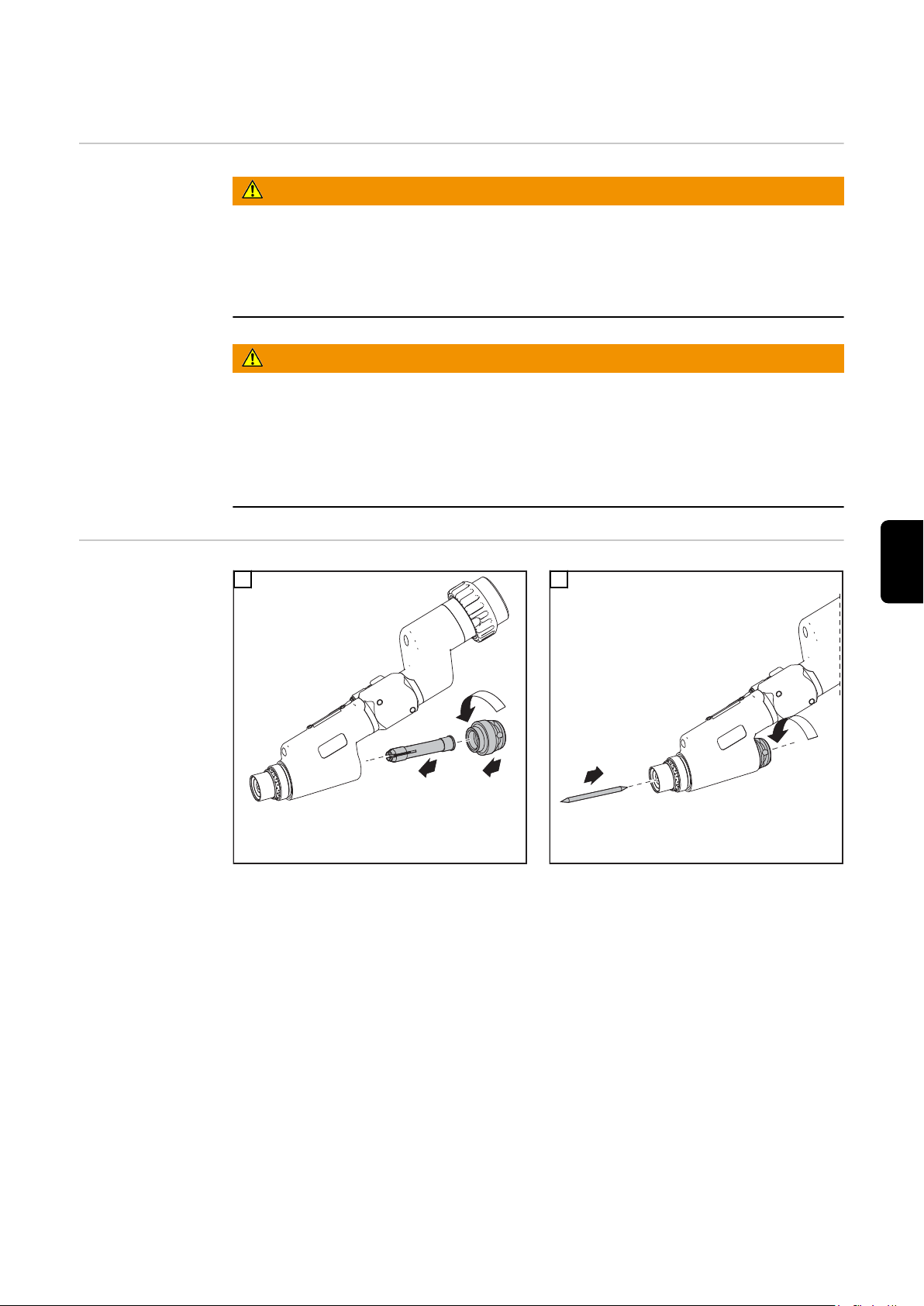
Montar a tocha de soldagem
2
3
1
1
2
Segurança
Montar PTW
PERIGO!
Trabalhos executados de forma incorreta podem causar danos graves a pessoas e
materiais.
Os trabalhos de conexão só podem ser executados por profissionais treinados de
▶
acordo com as normas de segurança em vigor!
Considere as normas de segurança na instrução de manuseio.
▶
PERIGO!
Um choque elétrico pode ser fatal.
Antes de trabalhar com a tocha de solda:
comutar o interruptor de rede elétrica da fonte de solda e do aparelho de plasma
▶
para a posição "0"
desconectar a fonte de solda e o aparelho de plasma da rede elétrica
▶
colocar um sinal de alerta claro para evitar o religamento
▶
1
2
PT-BR
IMPORTANTE! Colocar o eletrodo de tungstênio para que a ponta sobressaia a aprox.
10 mm do corpo da tocha. Apertar levemente a capa da tocha, ainda deveria ser
possível deslocar o eletrodo de tungstênio no corpo da tocha.
69
Page 70

1
2
4
3
*
* PTW 1500: 3 Nm
3
IMPORTANTE! Observar o ajuste correto do eletrodo de tungstênio (consultar capítulo
"Ajustar o eletrodo de tungstênio")
70
Page 71
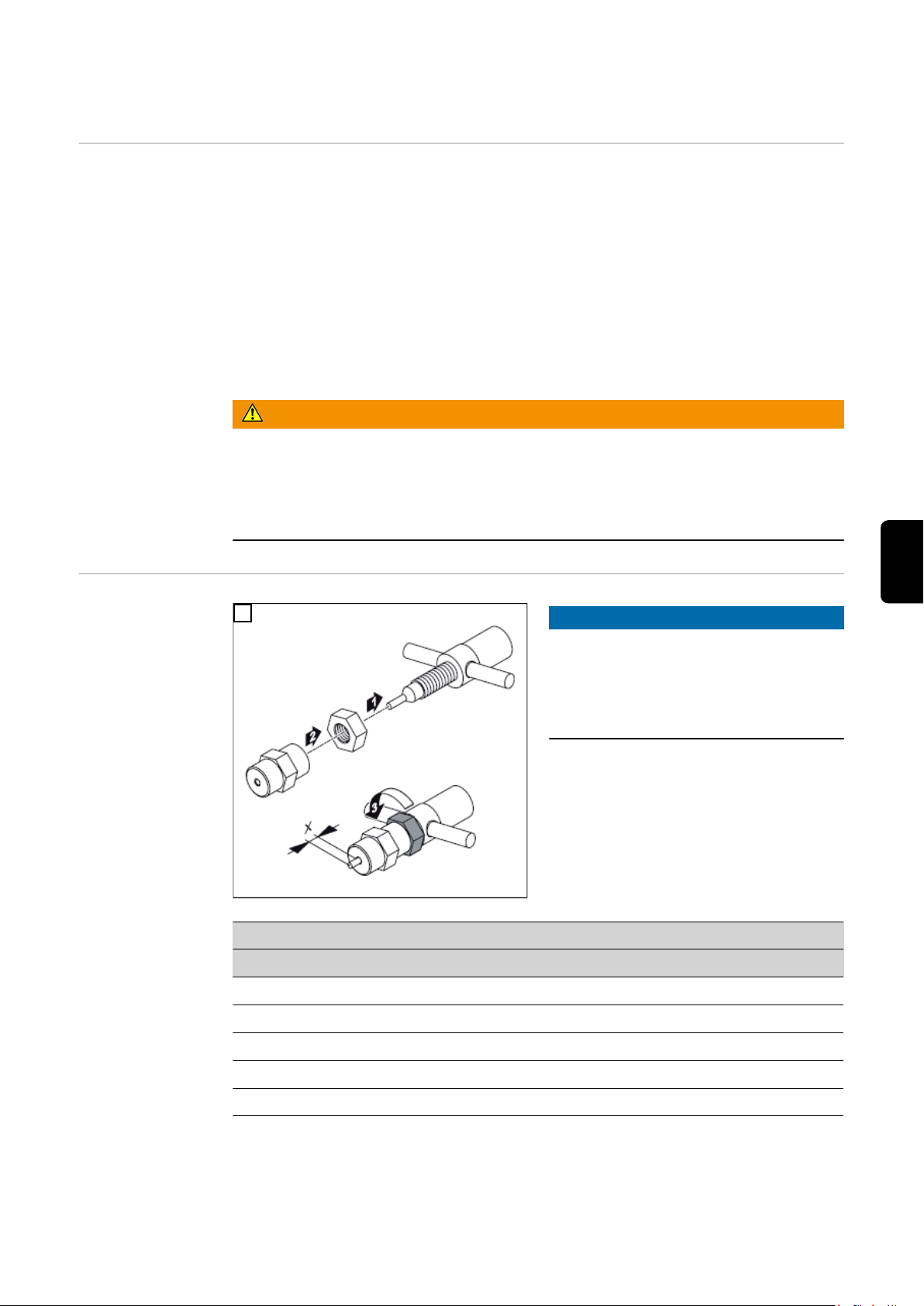
Ajustar o eletrodo de tungstênio
Informações
gerais
Ajustar o calibrador de ajuste
Por limites de carga, entende-se a corrente de soldagem máxima possível
- com um determinado bocal de plasma,
- com um determinado volume de gás de plasma,
- em uma determinada posição do eletrodo de tungstênio
- dependendo da potência de refrigeração do dispositivo de refrigeração.
A posição do eletrodo de tungstênio junto com o volume de gás de plasma ajustado é
crucial para os limites de carga.
O processo de ajuste para os eletrodos de tungstênio para a soldagem plasma/brasagem plasma é descrito na seção seguinte.
PERIGO!
Trabalhos executados de forma incorreta podem causar danos graves a pessoas e
materiais.
As atividades descritas em seguida devem ser executadas apenas por pessoal
▶
técnico treinado!
Observar as normas de segurança!
▶
1
AVISO!
O ajuste padrão para a medida "x" em
cada calibrador de ajuste depende do
diâmetro do bocal de plasma.
Fazer os ajustes padrão para a medida "x"
de acordo com a seguinte tabela:
PT-BR
PTW 1500
Ø bocal de plasma „x“ Calibrador de ajuste
1,0 mm - 1,5 mm 1,5 mm Ø 1,5 - 2 mm
2,0 mm 2,0 mm Ø 1,5 - 2 mm
2,5 mm 2,5 mm Ø 2,5 - 3 mm
3,0 mm 2,5 mm Ø 2,5 - 3 mm
71
Page 72

PTW 3500
1
1
1
Ø bocal de plasma „x“ Calibrador de ajuste
2,0 mm 2,0 mm Ø 1,5 - 2 mm
2,5 mm 2,0 mm Ø 1,5 - 2 mm
3,2 mm 2,5 mm Ø 2,5 - 3 mm
3,5 mm 3,0 mm Ø 2,5 - 3 mm
4,0 mm 3,0 mm Ø 2,5 - 3 mm
5,0 mm 4,0 mm Ø 2,5 - 3 mm
Ajustar o eletrodo de
tungstênio
1
3
2
4
72
Page 73

Diagnóstico de erro, eliminação de erro
Segurança
Diagnóstico de
erro, eliminação
de erro
PERIGO!
Um choque elétrico pode ser fatal.
Antes de trabalhar com a tocha de solda:
comutar o interruptor de rede elétrica da fonte de solda e do aparelho de plasma
▶
para a posição "0"
desconectar a fonte de solda e o aparelho de plasma da rede elétrica
▶
colocar um sinal de alerta claro para evitar o religamento
▶
Arco voltaico piloto não entra em ignição
Causa:
Solução:
Causa:
Solução:
Causa:
Solução:
Falta o eletrodo de tungstênio
Colocar o eletrodo de tungstênio
Distância grande demais entre o bocal de gás e eletrodo de tungstênio
Posicionar corretamente o eletrodo de tungstênio
Nenhuma distância ou pouca distância entre o bocal de plasma e eletrodo
de tungstênio (curto circuito entre o bocal de plasma e eletrodo de
tungstênio)
Posicionar corretamente o eletrodo de tungstênio
PT-BR
Pingos de cobre sobre o bocal de plasma após curto tempo de soldagem
Formação de pingos sobre o bocal de plasma é um sinal para um sério dano no bocal
de plasma: o bocal de plasma é fundido, devido à alta temperatura, e vaza.
Causa:
Solução:
Desgaste grande dos bocais de gás
Causa:
Solução:
HF é derivado para o robô
Causa:
Solução:
valores de carga altos demais
Controlar a quantidade de corrente e gás de plasma, substituir o bocal de
gás, reduzir a carga
Refrigeração ruim
Controlar a quantidade de corrente e gás de plasma, controlar o circuito de
refrigeração, aumentar a quantidade de gás de plasma, verificar o desgaste
da conexão dos bocais
Flange condutor de eletricidade do robô está montado
Montar o flange de plástico do robô
73
Page 74

Conservação, Manutenção e Descarte
Segurança
Informações
gerais
A cada comissionamento
PERIGO!
Um choque elétrico pode ser fatal.
Antes de trabalhar com a tocha de solda:
comutar o interruptor de rede elétrica da fonte de solda e do aparelho de plasma
▶
para a posição "0"
desconectar a fonte de solda e o aparelho de plasma da rede elétrica
▶
colocar um sinal de alerta claro para evitar o religamento
▶
A manutenção regular e preventiva da tocha é um fator importante para uma operação
sem falhas. A tocha de solda é submetida a altas temperaturas. Por isso, ela precisa de
manutenção com mais frequência que outros componentes do sistema de soldagem.
- Testar a tocha de plasma, o jogo de mangueiras da tocha e as conexões de corrente quanto a danos
- Verificar a estanqueidade das conexões de gás e água
- Verificar o dispositivo de refrigeração para a refrigeração da tocha de plasma
quanto ao funcionamento correto, monitorar a água e o volume de refluxo no recipiente de produto de refrigeração e, se necessário, purgar o dispositivo de refrigeração
- Verificar as peças de desgaste quanto ao perfeito estado, limpar as peças de desgaste antes da instalação
- Verificar o aperto da porca de capa (posição de acoplamento do jogo de mangueiras da tocha de plasma)
Mensalmente - Caso esteja disponível, verificar o filtro do circuito de refrigeração quanto a sujeiras
- Verificar o agente de refrigeração quanto à sua limpeza. Em caso de muita sujeira,
substituí-lo e enxaguar várias vezes a tocha de solda através do fluxo do agente de
refrigeração e do refluxo do agente de refrigeração
AVISO!
Sedimentos no interior da tocha de plasma podem causar descargas de alta
frequência e assim danificar a tocha de plasma
Desmontar a tocha de solda e verificar a existência de sedimentos/sujeiras
▶
Descarte O descarte pode ser executado somente de acordo com as determinações nacionais e
regionais em vigor.
74
Page 75

Dados técnicos
PTW 1500, PTW
3500
PTW 1500 PTW 3500
Alcance de potência 3 - 150 A 3 - 350 A
Valor máximo em 100% do ciclo de trabalho 150 A 350 A
Corrente do arco voltaico piloto 10 A 30 A
Dimensionamento de tensão (V-Peak) 141 V 141 V
Gás de Plasma/Gás de proteção (de acordo
com EN 439)
Sistema de refrigeração
agente de refrigeração
Potência de refrigeração 1000 W *) 1900 W *)
Pressão mín. do agente refrigerante 3,0 bar
Pressão máx. do agente refrigerante 5,5 bar
Taxa de fluxo mínima do agente de refrigeração 1,0 l/min. 1,0 l/min.
*) Refrigeração por líquido
**) Agente de refrigeração original da Fronius
***) Menor potência de refrigeração conforme norma CEI 60974-2
Argon Argon
*)
**)
43,50 psi.
79,74 psi.
*)
**)
3,0 bar
43,50 psi.
5,5 bar
79,74 psi.
PT-BR
Limites de carga,
dependendo do
volume de gás de
plasma
O produto está em conformidade com as exigências da norma IEC 60974-7.
Para a soldagem a plasma, os valores ajustados para o volume de gás de plasma e corrente de soldagem máxima devem estar dentro dos valores limites indicados. Valores
menores e maiores do que os calores limite causam uma alteração das propriedades do
plasma, por exemplo:
- Volume de gás de plasma mais baixo > jato de plasma "suave"
- Volume de gás de plasma mais altos > jato de plasma "duro" ("cortes a plasma")
AVISO!
Não ultrapassar os valores limite para valores de gás de plasma e corrente de soldagem máxima durante a operação.
AVISO!
A quantidade de fluxo mínima do agente de refrigeração é de 1 l/min.
Tabela válida somente para PTW 1500
Ø bocal de plasma Volume de gás de
plasma *
Corrente de soldagem máx.
1,5 mm mín. 0,30 l/mín.
máx. 0,80 l/min.
2,0 mm mín. 0,35 l/mín.
máx. 1,00 l/min.
60 A
100 A
80 A
120 A
75
Page 76

Ø bocal de plasma Volume de gás de
plasma *
Corrente de soldagem máx.
2,5 mm mín. 0,45 l/mín.
máx. 1,20 l/min.
3,0 mm mín. 0,55 l/mín.
máx. 1,30 l/min.
Tabela válida somente para PTW 3500 em conjunto com um dispositivo de refrigeração FK 9000
Ø bocal de plasma Volume de gás de
plasma *
2,0 mm mín. 1,0 l/min. 170 A
2,5 mm mín. 1,0 l/min. 190 A
3,2 mm mín. 1,0 l/min. 210 A
3,5 mm mín. 1,0 l/min. 225 A
4,0 mm mín. 1,0 l/min. 250 A
Tabela válida somente para PTW 3500 em conjunto com um dispositivo de refrigeração CHILLY 15
Ø bocal de plasma Volume de gás de
plasma *
2,0 mm mín. 1,0 l/min. 225 A
110 A
145 A
130 A
150 A
Corrente de soldagem máx.
Corrente de soldagem máx.
2,5 mm mín. 1,0 l/min. 250 A
3,2 mm mín. 1,0 l/min. 275 A
3,5 mm mín. 2,0 l/min. 300 A
4,0 mm mín. 2,0 l/min. 350 A
* Fator de correção do módulo plasma deve estar ajustado para automático
Volume mínimo de gás de plasma:
Volume de gás no qual o arco voltaico de soldagem ainda queima com estabilidade.
AVISO!
Soldagens com volumes mínimos de gás de plasma representam uma carga muito
alta para o bocal de gás e deveriam ser evitadas.
Corrente máxima de soldagem:
Corrente de soldagem, na qual um bocal de plasma, com ajuste padrão do eletrodo de
tungstênio, com volume mínimo de gás de plasma e dependendo do dispositivo de refrigeração é permitido.
Exemplo PTW 1500:
Em um bocal de plasma com um diâmetro de 2,0 mm, um volume mínimo de gás de
plasma ajustado em 0,25 l/min, no ajuste padrão do eletrodo de tungstênio é permitida
uma corrente de soldagem máxima de 80 A.
76
AVISO!
Como gás de plasma, usar argônio puro! Somente o argônio puro permite
alcançar os valores limite acima mencionados.
Page 77

Spis treści
Informacje ogólne 78
Koncepcja urządzenia 78
Obszary zastosowań 78
Zakres dostawy 78
Opcje PTW 1500 PAP 79
Opcje PTW 3500 PAP 80
Montaż palnika spawalniczego 81
Bezpieczeństwo 81
Montaż PTW 81
Ustawianie elektrody wolframowej 83
Informacje ogólne 83
Regulacja sprawdzianu nastawczego 83
Ustawianie elektrody wolframowej 84
Lokalizacja i usuwanie usterek 85
Bezpieczeństwo 85
Lokalizacja i usuwanie usterek 85
Czyszczenie, konserwacja i utylizacja 86
Bezpieczeństwo 86
Informacje ogólne 86
Podczas każdego uruchamiania 86
Comiesięczne czynności konserwacyjne 86
Utylizacja 86
Dane techniczne 87
PTW 1500, PTW 3500 87
Granice obciążenia w zależności od ilości gazu plazmotwórczego 87
PL
77
Page 78

Informacje ogólne
(9)
(1) (2) (3) (5)(4) (6) (7) (8)
Koncepcja
urządzenia
Obszary zastosowań
Chłodzone wodą plazmowe palniki spawalnicze do aplikacji zrobotyzowanych
PTW 1500 i PTW 3500 służą do spawania
łukowego plazmowego i plazmowego lutowania.
Uchwyty spawalnicze są seryjnie
wyposażone w przyłącze Fronius F++. W
celu umożliwienia eksploatacji z typowymi,
dostępnymi na rynku urządzeniami
plazmowymi do dyspozycji są odpowiednie adaptery. Każdy uchwyt spawalniczy
może być wyposażony w przesunięty KD
lub dyszę osłony gazowej wleczonej.
Pakiet przewodów można stosować także
do określonych uchwytów spawalniczych
TIG
Koncepcja urządzenia PTW 1500 / 3500 PAP
Palniki spawalnicze do aplikacji zrobotyzowanych są wykorzystywane, przykładowo,
w następujących zastosowaniach:
- podczas konstruowania rurociągów i agregatów;
- podczas budowy zbiorników;
- w przypadku konieczności spełnienia najwyższych wymogów jakościowych;
- w przypadku tworzyw specjalnych (np. tytan, stopy na bazie niklu);
- przemysł samochodowy.
Zakres dostawy
Zakres dostawy PTW 1500 PAP
78
Page 79

(1) Ceramiczna dysza gazu ochron-
(11)
(1) (4) (6) (7) (8) (9) (10)
(2)
(3)
(5)
nego
(2) Dysza plazmowa 2,5 mm
(3) Ceramiczna rurka centrująca 2,5
mm
(4) Pierścień izolacyjny
(5) Korpus palnika spawalniczego
PTW
(6) Elektroda wolframowa 2,4 mm
(7) Średnia nasadka palnika
(8) Pakiet przewodów ze zintegro-
wanym przewodem podającym
drut
(9) Sprawdzian nastawczy
Opcje PTW 1500
PAP
Zakres dostawy PTW 3500 PAP
(1) Ceramiczna dysza gazu ochron-
nego
(2) Pierścień sprężysty
(3) Pierścień izolacyjny
(4) Dysza plazmowa 3,2 mm
(5) Ceramiczna rurka centrująca 3,2
mm
(7) Elektroda wolframowa 4,8 mm
(8) Tuleja mocująca 4,8 mm
(9) Nasadka palnika krótka
(10) Pakiet przewodów ze zintegro-
wanym przewodem podającym
drut
(11) Sprawdzian nastawczy
(6) Korpus palnika spawalniczego
PTW
- Doprowadzanie zimnego drutu (system Push): Robacta KD Plasma / TIG PAP
- Dysza plazmowa (patrz lista części zamiennych)
- Ceramiczna rurka centrująca (patrz lista części zamiennych)
- Tuleja mocująca (patrz lista części zamiennych)
- Dysza osłony gazowej wleczonej 50 / 100 mm
- Sprawdzian nastawczy 1,5–2 mm
- Nasadki palnika
PL
79
Page 80

Opcje PTW 3500
PAP
- Doprowadzanie zimnego drutu (system Push): Robacta KD Plasma / TIG PAP
- Dysza plazmowa (patrz lista części zamiennych)
- Stożkowa dysza plazmowa
- Ceramiczna rurka centrująca (patrz lista części zamiennych)
- Tuleja mocująca (patrz lista części zamiennych)
- Dysza osłony gazowej wleczonej 50 / 100 mm / duża
- Dysze gazowe (patrz lista części zamiennych)
- Soczewka gazowa (chłodzona wodą)
- Nasadki palnika
- Sprawdzian nastawczy 2–3 mm
80
Page 81

Montaż palnika spawalniczego
2
3
1
1
2
Bezpieczeństwo
Montaż PTW
NIEBEZPIECZEŃSTWO!
Przeprowadzone nieprawidłowo prace mogą spowodować poważne szkody
osobowe i materialne.
Podłączanie mogą wykonywać tylko wykwalifikowani pracownicy przy zachowaniu
▶
obowiązujących przepisów bezpieczeństwa!
Należy przestrzegać przepisów bezpieczeństwa zawartych w instrukcji obsługi.
▶
NIEBEZPIECZEŃSTWO!
Porażenie prądem elektrycznym może spowodować śmierć.
Przed wykonaniem prac przy uchwycie spawalniczym:
Wyłącznik źródła energii i urządzenia plazmowego ustawić w pozycji „0”
▶
Odłączyć źródło energii oraz urządzenie plazmowe od sieci
▶
Umieścić wyraźną tabliczkę ostrzegającą przed ponownym włączeniem
▶
1
2
WAŻNE! Elektrodę wolframową należy włożyć tak, aby jej końcówka wystawała z kor-
pusu palnika spawalniczego ok. 10 mm. Pociągnąć lekko nasadkę palnika spawalniczego tak, aby elektroda wolframowa mogła jeszcze przesuwać się w korpusie palnika
spawalniczego.
PL
81
Page 82
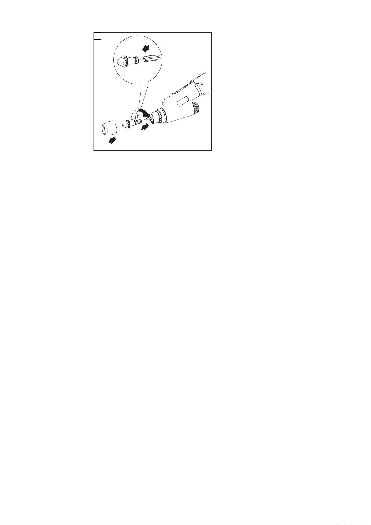
1
2
4
3
*
* PTW 1500: 3 Nm
3
WAŻNE! Należy zwracać uwagę na właściwe ustawienie elektrody wolframowej (patrz
rozdział „Ustawianie elektrody wolframowej”)
82
Page 83
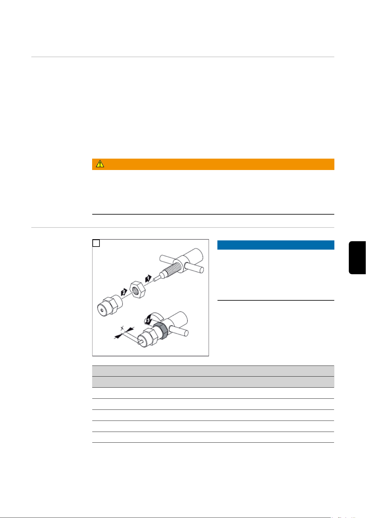
Ustawianie elektrody wolframowej
Informacje
ogólne
Regulacja
sprawdzianu
nastawczego
Pod granicami obciążenia rozumiany jest maksymalny możliwy prąd spawania
- w przypadku zastosowania określonej dyszy plazmowej,
- w przypadku zastosowania określonej ilości gazu plazmotwórczego,
- w przypadku zastosowania określonej pozycji elektrody wolframowej.
- w zależności od wydajności chłodzenia chłodnicy.
Pozycja elektrody wolframowej jest obok ustawionej ilości gazu plazmotwórczego czynnikiem decydującym dla granic obciążenia.
Proces ustawiania elektrody wolframowej do spawania plazmowego / lutowania plazmowego jest opisany w poniższych ustępach.
NIEBEZPIECZEŃSTWO!
Nieprawidłowo przeprowadzone prace mogą doprowadzić do powstania
poważnych obrażeń ciała oraz szkód materialnych.
Czynności opisane w dalszej części mogą być wykonywane wyłącznie przez
▶
przeszkolony personel specjalistyczny!
Przestrzegać przepisów dotyczących bezpieczeństwa!
▶
1
WSKAZÓWKA!
Standardowe ustawienie dla wymiaru
„x” w przypadku danego sprawdzianu
nastawczego jest uzależnione od średnicy dyszy plazmowej.
Dokonać standardowego ustawienia dla
wymiaru „x” zgodnie z poniższą tabelą:
PL
PTW 1500
Ø dyszy plazmowej „x” Sprawdzian nastawczy
1,0 mm - 1,5 mm 1,5 mm Ø 1,5–2 mm
2,0 mm 2,0 mm Ø 1,5–2 mm
2,5 mm 2,5 mm Ø 2,5–3 mm
3,0 mm 2,5 mm Ø 2,5–3 mm
83
Page 84
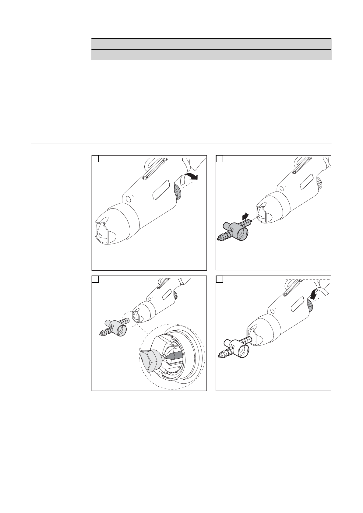
PTW 3500
1
1
1
Ø dyszy plazmowej „x” Sprawdzian nastawczy
2,0 mm 2,0 mm Ø 1,5–2 mm
2,5 mm 2,0 mm Ø 1,5–2 mm
3,2 mm 2,5 mm Ø 2,5–3 mm
3,5 mm 3,0 mm Ø 2,5–3 mm
4,0 mm 3,0 mm Ø 2,5–3 mm
5,0 mm 4,0 mm Ø 2,5–3 mm
Ustawianie elektrody wolframowej
1
3
2
4
84
Page 85

Lokalizacja i usuwanie usterek
Bezpieczeństwo
Lokalizacja i usuwanie usterek
NIEBEZPIECZEŃSTWO!
Porażenie prądem elektrycznym może spowodować śmierć.
Przed wykonaniem prac przy uchwycie spawalniczym:
Wyłącznik źródła energii i urządzenia plazmowego ustawić w pozycji „0”
▶
Odłączyć źródło energii oraz urządzenie plazmowe od sieci
▶
Umieścić wyraźną tabliczkę ostrzegającą przed ponownym włączeniem
▶
Łuk pilotujący nie zajarza się
Przyczyna:
Usuwanie:
Przyczyna:
Usuwanie:
Przyczyna:
Usuwanie:
Pojawianie się kropli miedzi na dyszy plazmowej po krótkim czasie spawania
Pojawianie się takich kropli na dyszy plazmowej jest objawem poważnego uszkodzenia
dyszy plazmowej: dysza plazmowa z powodu zbyt wysokiej temperatury ulega wytopieniu i wypływa.
Brak elektrody wolframowej
Włożyć elektrodę wolframową
Zbyt duży odstęp pomiędzy dyszą plazmową a elektrodą wolframową
Nadać elektrodzie wolframowej właściwą pozycję
Brak lub za mały odstęp pomiędzy dyszą plazmową a elektrodą wolframową (zwarcie pomiędzy dyszą plazmową a elektrodą wolframową)
Nadać elektrodzie wolframowej właściwą pozycję
PL
Przyczyna:
Usuwanie:
Wysokie zużycie dyszy plazmowej
Przyczyna:
Usuwanie:
Iskra zapłonowa jest odprowadzana do robota
Przyczyna:
Usuwanie:
Za wysokie wartości obciążenia
Skontrolować ilość prądu i gazu plazmotwórczego, wymienić dyszę
plazmową, zredukować obciążenie
Niewłaściwe chłodzenie
Skontrolować ilość prądu i gazu plazmotwórczego, skontrolować układ
chłodzenia, zwiększyć ilość gazu plazmotwórczego, sprawdzić zużycie
przyłącza dyszy
Zamontowany kołnierz robota przewodzący prąd elektryczny
Zamontować kołnierz robota z tworzywa sztucznego
85
Page 86
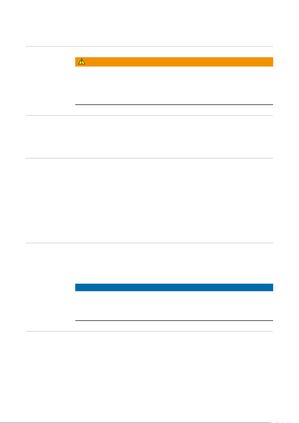
Czyszczenie, konserwacja i utylizacja
Bezpieczeństwo
Informacje
ogólne
Podczas każdego
uruchamiania
NIEBEZPIECZEŃSTWO!
Porażenie prądem elektrycznym może spowodować śmierć.
Przed wykonaniem prac przy uchwycie spawalniczym:
Wyłącznik źródła energii i urządzenia plazmowego ustawić w pozycji „0”
▶
Odłączyć źródło energii oraz urządzenie plazmowe od sieci
▶
Umieścić wyraźną tabliczkę ostrzegającą przed ponownym włączeniem
▶
Regularna i profilaktyczna konserwacja palnika spawalniczego to istotny czynnik, zapewniający bezawaryjną eksploatację. Palnik spawalniczy jest wystawiony na działanie
bardzo wysokich temperatur. Z tego powodu wymaga on częstszej konserwacji niż
pozostałe podzespoły systemu spawania.
- Sprawdzić plazmowy palnik spawalniczy, wiązkę uchwytu palnika spawalniczego i
przyłącza prądu pod kątem uszkodzeń
- Sprawdzić szczelność przyłączy wody i gazu.
- Skontrolować chłodnicę chłodzącą plazmowy palnik spawalniczy pod kątem prawidłowego działania, monitorować ilość odpływającej wody w zbiorniku płynu
chłodzącego, ewentualnie odpowietrzyć chłodnicę
- Skontrolować elementy plazmowego palnika spawalniczego ulegające zużyciu pod
kątem ich niebudzącego zastrzeżeń stanu, przed montażem elementów ulegających
zużyciu należy je oczyścić
- sprawdzić odpowiednie zamocowanie nakrętki łączącej (miejsce połączenia pakiet
przewodów – plazmowy palnik spawalniczy)
Comiesięczne
czynności konserwacyjne
Utylizacja Utylizację przeprowadzać zgodnie z obowiązującymi krajowymi przepisami w tym zakre-
- Jeśli jest obecny: skontrolować filtr w układzie chłodzenia pod kątem zabrudzenia.
- Skontrolować płyn chłodzący pod kątem czystości; w przypadku stwierdzenia
większych zanieczyszczeń należy wymienić płyn chłodzący i kilkakrotnie przepłukać
plazmowy palnik spawalniczy przez dopływ i odpływ płynu chłodzącego.
WSKAZÓWKA!
Osady we wnętrzu plazmowego palnika spawalniczego mogą wywołać przebicia
wysokiej częstotliwości i w ten sposób uszkodzić plazmowy palnik spawalniczy.
Rozmontować plazmowy palnik spawalniczy na części i skontrolować pod kątem
▶
osadów / zanieczyszczeń
sie.
86
Page 87
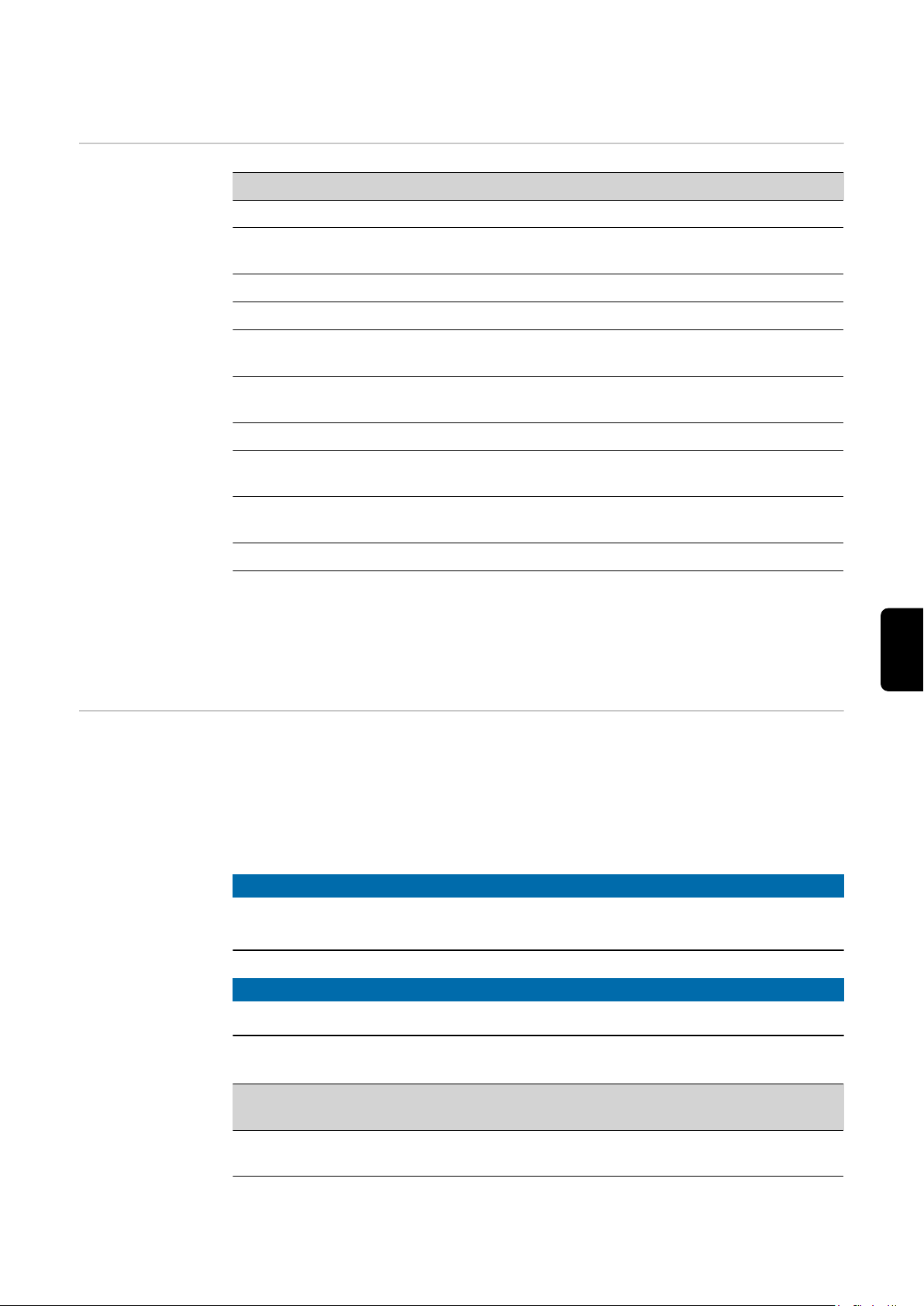
Dane techniczne
PTW 1500, PTW
3500
PTW 1500 PTW 3500
Zakres prądu 3–150 A 3–350 A
Wartość maksymalna przy czasie włączenia
100%
Prąd łuku pilotującego 10 A 30 A
Pomiar napięcia (V-Peak) 141 V 141 V
Gaz plazmotwórczy / gaz osłonowy (zgodnie z
EN 439)
System chłodzenia
Płyn chłodzący
Wydajność chłodzenia 1000 W ***) 1900 W ***)
Ciśnienie płynu chłodzącego min. 3,0 bary
Ciśnienie płynu chłodzącego maks. 5,5 bara
Minimalny przepływ płynu chłodzącego 1,0 l/min 1,0 l/min
*) Chłodzenie płynem chłodzącym
**) Chłodziwo oryginalne Fronius
***) Najniższa wydajność chłodzenia zgodnie z normą IEC 60974-2
Produkt spełnia wymogi normy IEC 60974-7
150 A 350 A
Argon Argon
*)
**)
43,50 psi.
79,74 psi.
*)
**)
3,0 bary
43,50 psi.
5,5 bara
79,74 psi.
PL
Granice
obciążenia w
zależności od
ilości gazu
plazmotwórczego
Podczas spawania łukowego plazmowego wartości ustawione dla ilości gazu
plazmotwórczego oraz maksymalnego prądu spawania muszą znajdować się w obrębie
podanych wartości granicznych. Spadek poniżej dolnej lub przekroczenie górnej wartości
granicznej pociąga za sobą zmianę właściwości plazmy, np.:
- mała ilość gazu plazmotwórczego „bardziej miękka” wiązka plazmowa
- duża ilość gazu plazmotwórczego „twardsza“ wiązka plazmowa („cięcie plazmowe”)
WSKAZÓWKA!
Podczas eksploatacji wartości graniczne dla gazu plazmotwórczego i maks. prądu
spawania nie mogą znajdować się poniżej dolnej wartości.
WSKAZÓWKA!
Minimalny przepływ płynu chłodzącego wynosi1 l/min
Tabela dotyczy tylko PTW 1500
Ø dyszy plazmowej ilość gazu
plazmotwórczego *
1,5 mm min. 0,30 l/min
maks. 0,80 l/min
maks. prąd spawania
60 A
100 A
87
Page 88
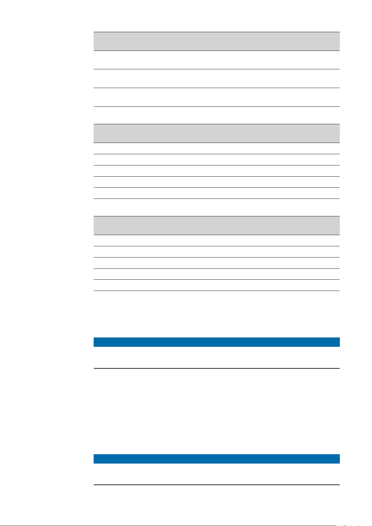
Ø dyszy plazmowej ilość gazu
plazmotwórczego *
maks. prąd spawania
2,0 mm min. 0,35 l/min
maks. 1,00 l/min
2,5 mm min. 0,45 l/min
maks. 1,20 l/min
3,0 mm min. 0,55 l/min
maks. 1,30 l/min
Tabela dotyczy tylko PTW 3500 w połączeniu z chłodnicą FK 9000
Ø dyszy plazmowej ilość gazu
plazmotwórczego *
2,0 mm min. 1,0 l/min 170 A
2,5 mm min. 1,0 l/min 190 A
3,2 mm min. 1,0 l/min 210 A
3,5 mm min. 1,0 l/min 225 A
4,0 mm min. 1,0 l/min 250 A
Tabela dotyczy tylko PTW 3500 w połączeniu z chłodnicą CHILLY 15
Ø dyszy plazmowej ilość gazu
plazmotwórczego *
80 A
120 A
110 A
145 A
130 A
150 A
maks. prąd spawania
maks. prąd spawania
2,0 mm min. 1,0 l/min 225 A
2,5 mm min. 1,0 l/min 250 A
3,2 mm min. 1,0 l/min 275 A
3,5 mm min. 2,0 l/min 300 A
4,0 mm min. 2,0 l/min 350 A
* współczynnik korekcji modułu plazmowego musi być ustawiony na tryb automatyczny
Minimalna ilość gazu plazmotwórczego:
ilość gazu, przy której łuk spawalniczy jest wciąż stabilny.
WSKAZÓWKA!
Spawania przy zastosowaniu minimalnej ilości gazu plazmotwórczego są bardzo
obciążające dla dyszy plazmowej i z tego powodu należy ich unikać.
Maksymalny prąd spawania:
prąd spawania dopuszczalny w przypadku zastosowania określonej dyszy plazmowej,
przy standardowym ustawieniu elektrody wolframowej, przy minimalnej ilości gazu
plazmotwórczego i w zależności od chłodnicy.
Przykład PTW 1500:
Przy średnicy dyszy plazmowej wynoszącej 2,0 mm i ustawionej minimalnej ilości gazu
plazmotwórczego wynoszącej 0,25 l/min, przy standardowym ustawieniu elektrody wolframowej maksymalna dopuszczalna wartość prądu spawania wynosi 80 A.
88
WSKAZÓWKA!
Jako gazu plazmotwórczego należy używać czystego argonu! Tylko czysty argon
gwarantuje uzyskanie wyżej wymienionych wartości granicznych.
Page 89

PL
89
Page 90

90
Page 91

PL
91
Page 92

FRONIUS INTERNATIONAL GMBH
Froniusstraße 1
A-4643 Pettenbach
AUSTRIA
contact@fronius.com
www.fronius.com
Under www.fronius.com/contact you will find the addresses
of all Fronius Sales & Service Partners and locations.
 Loading...