

Page 1

/ Battery Charging Systems / Welding Technology / Solar Electronics
PT-Drive
Bedienungsanleitung
DEENFR
MIG/MAG-Push-Pull-Schlauchpaket
Operating Instructions
MIG/MAG-Push-Pull-hosepack
Mode d’emploi
Jeu de flexibles MIG/MAG-PushPull
42,0410,0997 002-02042012
Page 2

Page 3

Sehr geehrter Leser
DE
Einleitung
Wir danken Ihnen für Ihr entgegengebrachtes Vertrauen und gratulieren Ihnen zu Ihrem
technisch hochwertigen Fronius Produkt. Die vorliegende Anleitung hilft Ihnen, sich mit
diesem vertraut zu machen. Indem Sie die Anleitung sorgfältig lesen, lernen Sie die
vielfältigen Möglichkeiten Ihres Fronius-Produktes kennen. Nur so können Sie seine
Vorteile bestmöglich nutzen.
Bitte beachten Sie auch die Sicherheitsvorschriften und sorgen Sie so für mehr Sicherheit am Einsatzort des Produktes. Sorgfältiger Umgang mit Ihrem Produkt unterstützt
dessen langlebige Qualität und Zuverlässigkeit. Das sind wesentliche Voraussetzungen
für hervorragende Ergebnisse.
ud_fr_st_et_00491 01/2012
Page 4

Page 5

Inhaltsverzeichnis
PT-Drive ........................................................................................................................................................ 3
Sicherheit ................................................................................................................................................. 3
Übersicht Draht-Förderkomponenten....................................................................................................... 3
Einstellen der Schweißleistung ................................................................................................................ 4
Allgemeines ............................................................................................................................................. 4
Systemvoraussetzungen .......................................................................................................................... 4
Erstausrüstung .............................................................................................................................................. 5
Lieferumfang Erstausrüstung ................................................................................................................... 5
Mitgeliefertes Werkzeug................................................................................................................................ 5
Werkzeug ................................................................................................................................................. 5
Draht-Führungsseele für Rohrbogen austauschen ....................................................................................... 6
Sicherheit ................................................................................................................................................. 6
Benötigtes Werkzeug ............................................................................................................................... 6
Rohrbogen vom PT-Drive abmontieren.................................................................................................... 6
Gasdüse und Kontaktrohr demontieren ................................................................................................... 6
Draht-Führungsseele positionieren .......................................................................................................... 7
Draht-Führungsseele ablängen ................................................................................................................ 7
Rohrbogen am PT-Drive abschrauben..................................................................................................... 8
Draht-Führungsseele für Schlauchpaket montieren / austauschen bei Anschluss Fronius........................... 9
Sicherheit ................................................................................................................................................. 9
Benötigtes Werkzeug ............................................................................................................................... 9
Brennerschlauchpaket abmontieren ........................................................................................................ 9
Draht-Führungsseele ausbauen ............................................................................................................... 9
Draht-Führungsseele einbauen .............................................................................................................. 10
DE
Draht-Führungseele für Schlauchpaket montieren / austauschen bei Anschluss Euroconnector ............... 12
Sicherheit ............................................................................................................................................... 12
Benötigtes Werkzeug ............................................................................................................................. 12
Schweißbrenner-Schlauchpaket abmontieren ....................................................................................... 12
Draht-Führungsseele ausbauen ............................................................................................................. 12
Draht-Führungsseele einbauen .............................................................................................................. 12
Brennerschlauchpaket anschließen / abmontieren ..................................................................................... 14
Sicherheit ............................................................................................................................................... 14
PT-Drive anschließen ............................................................................................................................. 14
Drahtführungs-Düsen austauschen............................................................................................................. 15
Sicherheit ............................................................................................................................................... 15
Benötigtes Werkzeug ............................................................................................................................. 15
Rohrbogen vom PT-Drive abschrauben ................................................................................................. 15
Draht-Auslaufdüse ausbauen................................................................................................................. 16
Draht-Auslaufdüse einbauen.................................................................................................................. 16
Draht-Einlaufdüse ausbauen.................................................................................................................. 16
Draht-Einlaufdüse einbauen ................................................................................................................... 17
Rohrbogen am PT-Drive montieren ....................................................................................................... 17
Anpressdruck am PT-Drive definieren ........................................................................................................ 18
Sicherheit ............................................................................................................................................... 18
Druckfeder ............................................................................................................................................. 18
Benötigtes Werkzeug ............................................................................................................................. 18
Rohrbogen vom PT-Drive abnehmen..................................................................................................... 18
Bestehende Druckfeder ausbauen......................................................................................................... 19
Neue Druckfeder einbauen .................................................................................................................... 19
Drahtelektrode einlaufen lassen .................................................................................................................. 21
Sicherheit ............................................................................................................................................... 21
PT-Drive vorbereiten .............................................................................................................................. 21
Drahtelektrode einfädeln ........................................................................................................................ 21
Nachbereiten .......................................................................................................................................... 22
1
Page 6

Anpressdruck am Drahtvorschub einstellen................................................................................................ 22
Anpressdruck am Drahtvorschub einstellen........................................................................................... 22
Konfigurationstabelle ................................................................................................................................... 23
Inhalte der Konfigurationstabelle ............................................................................................................ 23
Konfigurationstabelle.............................................................................................................................. 23
PushPull-Abgleich ....................................................................................................................................... 24
Allgemeines ........................................................................................................................................... 24
PushPull-Abgleich .................................................................................................................................. 24
Service-Codes PushPull-Abgleich............................................................................................................... 26
Sicherheit ............................................................................................................................................... 26
Angezeigte Fehlercodes bei entkoppelten Antriebseinheiten (Leerlaufabgleich) ................................... 26
Angezeigte Fehlercodes bei gekoppelten Antriebseinheiten (gekoppelter Abgleich) ............................. 27
Fehlerdiagnose und -behebung .................................................................................................................. 29
Allgemeines ........................................................................................................................................... 29
Fehlerdiagnose PT-Drive ....................................................................................................................... 29
Pflege, Wartung und Entsorgung ................................................................................................................ 31
Allgemeines ........................................................................................................................................... 31
Bei jeder Inbetriebnahme ....................................................................................................................... 31
Nach jedem Austausch der Drahtspule .................................................................................................. 32
Draht-Führungsseele reinigen ................................................................................................................ 32
Schweißbrenner-Schlauchpaket reinigen............................................................................................... 33
Nach Verbrauch von zwei Drahtspulen .................................................................................................. 33
Entsorgung ............................................................................................................................................. 33
Technische Daten: Rohrbogen .................................................................................................................... 34
Technische Daten: Schlauchpaket .............................................................................................................. 35
2
Page 7

PT-Drive
DE
Sicherheit
Übersicht DrahtFörderkomponenten
WARNUNG! Fehlbedienung kann schwerwiegende Personen- und Sachschä-
den verursachen. Vor Inbetriebnahme des PT-Drive, müssen Sie folgende
Dokumente unbedingt vollständig gelesen und verstanden haben:
- Das beiliegende Dokument „Sicherheitsvorschriften“
- Die Bedienungsanleitung PT-Drive
- Die Bedienungsanleitung Stromquelle, insbesondere das Kapitel Sicherheitsvorschriften
VORSICHT! Verletzungsgefahr durch rotierende Teile. Den PT-Drive nur bei
geschlossenem Deckel betreiben.
(5) (3)
(1)(2) (4)
(2)
Abb.1 Übersicht der wichtigsten Komponenten am PT-Drive
(5)
(3)
(1) Rändelmutter
(2) Antriebs-Kopf
(3) Spannkegel
(4)(6)
(7a): 0,8 mm (.030 in.)
(7b): 1,0 mm (.040 in.)
(7c): 1,2 mm (.045 in.)
(7d): 1,6 mm (1/16 in.)
(5) Druckfeder
(6) Auslaufdüse
(7) Einlaufdüse
(4) Spannhebel
(1)
3
Page 8

Einstellen der
Schweißleistung
(29)
Abb.2 Einstellpotentiometer auf Stellung „9“
Das Einstellpotentiometer (29) dient zum
Einstellen der Schweißleistung
- 0 ..... minimale Schweißleistung
- 9 ..... maximale Schweißleistung
Wichtig! Minimale und maximale
Schweißleistung sind abhängig von
- Der verwendeten Stromquelle
- Dem angewählten Material
Allgemeines
Systemvoraussetzungen
PT Drive ist ein extrem kleines, leichtes und kompaktes Drahtfördergerät für das Handschweißen bei weichen Schweißdrähten und langen Schlauchpaketen.
Zwei im Winkel von 90° zueinander angeordnete Präzisionsrollen erzeugen einen
großflächigen Kontakt zum Drahtelektrode. Dank der großflächigen Kraftübertragung
führt dies selbst bei sehr weichen Aluminium- und CuSi-Drähten und sehr langen
Schlauchpaketen zu einer hervorragenden Drahtförderung.
Sie können den PT Drive mit folgenden Stromquellen kombinieren:
- TransSynergic 4000 / 5000
- TransPuls Synergic 2700 / 2700 Duo / 2700 TIG / 2700 DuoTIG
- TransPuls Synergic 4000 / 5000
Die Stromquellen und Drahtvorschübe müssen mindestens über folgende SoftwareVersionen verfügen:
- Stromquelle
- Software-Version 3.10.22 oder höher
- Drahtvorschub bzw. der in die Stromquelle TPS 2700 integrierte Drahtantrieb
- Software-Version 1.70.16 oder höher
Zusätzlich benötigen Sie für die Stromquelle folgende Optionen:
- Einbauset „PMR4000 PullMig TS/TPS 2700-5000 (4,100,217)“
- Software „FS Drive (4,061,113)“
Der PT Drive ist derzeit für folgende Drahtelektrode-Durchmesser geeignet:
- 0,8 mm (.030 in.)
- 1,0 mm (.040 in.)
- 1,2 mm (.045 in.)
- 1,6 mm (1/16 in.)
Die genauen Einstellinformationen entnehmen Sie bitte der Tabelle im Anhang dieses
Dokumentes.
4
Page 9

Erstausrüstung
DE
Lieferumfang
Erstausrüstung
Mit der Erstausrüstung PT-Drive (Option) mitgeliefertes Zubehör:
Pos. Bezeichnung Stück
(5) Druckfeder ............................................................................. 1
(6) Draht-Auslaufdüse .................................................................1
(7) Draht-Einlaufdüse .................................................................. 1
(22) Draht-Führungsdüse Schlauchpaket......................................1
(21) Draht-Führungsseele ............................................................. 1
Erstausrüstung für Aluminium-Legierungen AlMg
(6) (5) (7) (22)
(21)
Erstausrüstung für Aluminium-Legierungen AlSi
(6) (5) (7) (22)
(21)
Erstausrüstung für Stahl und Chrom-Nickel
(6) (5) (7) (22)
(21)
Mitgeliefertes Werkzeug
Werkzeug
(B)
Bezeichnung
(A) Gabelschlüssel, Schlüsselweite
8 mm / 10 mm (.32 in. / .39 in.)
(B) Flachschraubendreher
6,5 mm (.26 in.)
Abb.2a Mitgeliefertes Werkzeug
(A)
5
Page 10

Draht-Führungsseele für Rohrbogen austauschen
Sicherheit
Benötigtes
Werkzeug
WARNUNG! Fehlerhaft durchgeführte Arbeiten können schwerwiegende Perso-
nen- und Sachschäden verursachen. Nachfolgend beschriebene Tätigkeiten
dürfen nur von Fronius-geschultem Fachpersonal durchgeführt werden! Beachten
Sie die Sicherheitsvorschriften.
WARNUNG! Gefahr durch elektrischen Schlag und austretende Drahtelektrode.
Vor dem Durchführen der nachfolgend beschriebenen Arbeitsschritte, die Stromquelle vom Netz trennen und den Netzschalter in Stellung „O“ schalten.
Abb.3 Gabelschlüssel und Seitenschneider
Bei Kontaktrohr M6 und M8:
- Gabelschlüssel
Schlüsselweite 7 mm (.28 in.)
- alternativ: Kontaktrohrschlüssel
Schlüsselweite 7 mm (.28 in.)
Artikelnummer: 42,0410,0570
Bei Kontaktrohr M10:
- Gabelschlüssel
Schlüsselweite 8 mm (.32 in.)
- alternativ: Kontaktrohrschlüssel
Schlüsselweite 8 mm (.32 in.)
Artikelnummer: 42,0410,0138
Rohrbogen vom
PT-Drive abmontieren
Gasdüse und
Kontaktrohr
demontieren
(29)
Abb.4 Rohrbogen abmontieren
- Überwurfmutter (13) lösen und Rohrbogen (14) vom PT-Drive abnehmen
- Gasdüse (29) von der Fixierhülse (30) abziehen
(15)
(14)
(13)(30)
- Kontaktrohr (15) abschrauben
M6/M8 ... mittels Gabelschlüssel oder
Kontaktrohrschlüssel
Schlüsselweite 7 mm (.28 in.)
M10 ... mittels Gabelschlüssel oder
Kontaktrohrschlüssel
Schlüsselweite 8 mm (.32 in.)
Abb.5 Kontaktrohr abschrauben
6
Page 11

Draht-Führungsseele positionieren
(16) (13)
Abb.6 Neue Draht-Führungsseele positionieren
(14)
HINWEIS!Gefahr der Beschädigung des Gewindes. Kontaktrohr und Gasdüse
vor der Montage reinigen.
(15) (16)
Abb.7 Draht-Führungsseele zurückschieben und
Kontaktrohr festschrauben
HINWEIS! Gefahr von Beschädigung durch Verunreinigungen.
Vor dem Einschieben der DrahtFührungsseele, das Innere des
Rohrbogens mit trockener,
reduzierter Pressluft ausblasen.
- Draht-Führungsseele (16) VORSICHTig bei der Überwurfmutter (13)
einschieben
- Draht-Führungsseele (16) gemeinsam
mit Kontaktrohr (15) einschieben
- Kontaktrohr (15) am Brennerkörper
festschrauben
M6/M8 ... mittels Gabelschlüssel oder
Kontaktrohrschlüssel
Schlüsselweite 7 mm (.28 in.)
M10 ... mittels Gabelschlüssel oder
Kontaktrohrschlüssel
Schlüsselweite 8 mm (.32 in.)
- Gasdüse montieren
DE
Draht-Führungsseele ablängen
(16)(14) (13)
(18)
16,5 mm
(.65 in.)
Abb.8 Erforderliches Maß für das Ablängen der Draht-Führungsseele
HINWEIS! Das Kontaktrohr, im Rohrbogen (14), muss fest montiert sein.
Ein genaues Ablängen der Draht-Führungsseele (16), bei der Überwurfmutter (13), ist
erforderlich. Die Vorgehensweise mittels Ablänghülse (18) entnehmen Sie Abb.9.
7
Page 12

Draht-Führungsseele ablängen
(Fortsetzung)
(14)
1.
(16)
(18)
(14)
2.
15,5 mm
(.61 in.)
(16)
(18)
16,5 mm
(.65 in.)
Abb.9 Draht-Führungsseele mittels Ablänghülse ablängen
- Mitgelieferte Ablänghülse (18) bis zum Anschlag auf den Rohrbogen (14) aufschieben (Abb.9, 1.)
- Draht-Führungsseele (16) an der Stirnfläche der Ablänghülse (18) mittels Seitenschneider durchtrennen (Abb.9, 1.)
Die Draht-Führungsseele (16) darf anschließend maximal nur mehr um eine Windung
aus der Bohrung an der Ablänghülse (18) ragen (Abb.9, 2.).
Wichtig! Die Ablänghülse besitzt eine Länge von 15,5 mm (.61 in.). Unter Berücksichtigung der erwähnten Überlänge von einer Windung, ergibt sich daraus das gewünschte
Maß von ungefähr 16,5 mm (.65 in.).
Rohrbogen am
PT-Drive abschrauben
- Ablänghülse (18) vom Rohrbogen (14) abnehmen
Abb.10 Rohrbogen montieren
(14)
(13)
(16)
HINWEIS! Beim Montieren des Rohrbogens am PT-Drive darauf achten, dass
die Draht-Führungsseele (16) knickfrei in die dafür vorgesehene Bohrung am
PT-Drive gleitet.
- Rohrbogen (14) mittels Überwurfmutter (13) am PT-Drive montieren
8
Page 13

Draht-Führungsseele für Schlauchpaket montieren /
austauschen bei Anschluss Fronius
DE
Sicherheit
Benötigtes
Werkzeug
Brennerschlauchpaket
abmontieren
Draht-Führungsseele ausbauen
WARNUNG! Fehlerhaft durchgeführte Arbeiten können schwerwiegende Perso-
nen- und Sachschäden verursachen. Nachfolgend beschriebene Tätigkeiten
dürfen nur von Fronius-geschultem Fachpersonal durchgeführt werden! Beachten
Sie die Sicherheitsvorschriften.
WARNUNG! Gefahr durch elektrischen Schlag und austretende Drahtelektrode.
Vor dem Durchführen der nachfolgend beschriebenen Arbeitsschritte, die Stromquelle vom Netz trennen und den Netzschalter in Stellung „O“ schalten.
- Gabelschlüssel
(Schlüsselweite 10 mm - .39 in.)
- Messer
Kapitel „Brennerschlauchpaket abmontieren“
Ausführung ohne zusätzliche Draht-Führungsdüse
- Spitzzange
(19) (20) (21)
Abb.11 Spannmutter lösen Abb.12 Spannstück lösen
- Beim Anschluss Schweißbrenner Spannmutter (19) und anschließend Spannstück
(20) lösen, mittels Gabelschlüssel, Schlüsselweite 10 mm = .39 in.
- Bestehende Draht-Führungsseele (21) herausziehen
Ausführung mit zusätzlicher Draht-Führungsdüse
(19) (22)
Abb.13 Spannmutter lösen
- Beim Anschluss Schweißbrenner Spannmutter (19) - komplett mit Draht-Führungsdüse (22) - abmontieren und anschließend Spannstück (20) lösen
mittels Gabelschlüssel, Schlüsselweite 10 mm = .39 in.
- Bestehende Draht-Führungsseele (21) herausziehen
Abb.14 Spannmutter lösen
(20)(21)
9
Page 14

Draht-Führungsseele ausbauen
(Fortsetzung)
Wichtig! In Abhängigkeit des Drahtdurchmessers besitzt die Draht-Führungsdüse (22)
folgende farbliche Kennzeichnung:
- 0,8 mm und .030 in. (grau)
- 1,0 mm und .040 in. (blau)
- 1,2 mm und .045 in. (rot)
- 1,6 mm und 1/16 in. (schwarz)
Draht-Führungsseele einbauen
HINWEIS! Gefahr von Beschädigung durch Verunreinigungen. Vor dem Ein-
schieben der Draht-Führungsseele, das Innere des Rohrbogens wie folgt mit
trockener, reduzierter Druckluft sauberblasen:
(21)
- Neue Draht-Führungsseele (21)
Abb.15 Draht-Führungsseele einschieben
VORSICHTig einschieben, bis ein
Weiterschieben nicht mehr möglich
ist.
Ausführung ohne zusätzliche Draht-Führungsdüse
HINWEIS!Gefahr der Beschädigung des Gewindes. Spannstück und Spannmut-
ter vor der Montage reinigen.
Wichtig! Folgende Arbeitsschritte gelten
(20)
(19)
nur für Drahtförderseelen ohne Drahtführungs-Düse an der Seite des Anschlusses
Schweißbrenner.
(21)
- Beim Anschluss Schweißbrenner
Spannstück (20) montieren und
1 - 2 mm
.04 - .08 in.
anschließend Spannmutter (19)
festschrauben (Gabelschlüssel
Schlüsselweite 10 mm - .39 in.)
Abb.16 Draht-Führungsseele ablängen
HINWEIS! Gefahr des Knickens
der Draht-Führungsseele. Vor
dem Einschieben, das Schlauchpaket gerade auslegen. Sobald
ein Widerstand spürbar wird, die
Draht-Führungsseele nur mehr in
der Nähe des Drahteinlaufrohres
anschieben.
- Draht-Führungsseele (21) gemäß Abb.14 an der Spannmutter (19) ablängen
10
Page 15

Draht-Führungsseele einbauen
(Fortsetzung)
Ausführung mit zusätzlicher Draht-Führungsdüse
HINWEIS!Gefahr der Beschädigung des Gewindes. Spannstück und Spannmut-
ter vor der Montage reinigen.
DE
(21)(20)
Wichtig! Folgende Arbeitsschritte gelten
nur für Drahtförderseelen mit Drahtführungs-Düse beim Anschluss Schweißbrenner.
- Beim Anschluss Schweißbrenner
Spannstück (20) festschrauben
Abb.17 Draht-Führungsseele bündig mit Spann-
stück ablängen
(Gabelschlüssel Schlüsselweite10
mm - .39 in.)
- Draht-Führungsseele (21) bündig mit dem Spannstück (20) ablängen
- Spannmutter (19) - komplett mit
(19) (22)
Draht-Führungsdüse (22) - festschrauben (Gabelschlüssel Schlüsselweite 10 mm - .39 in.)
Abb.18 Spannmutter festschrauben
Wichtig! In Abhängigkeit des Drahtdurchmessers besitzt die Draht-Führungsdüse (22)
folgende farbliche Kennzeichnung:
- 0,8 mm und .030 in. (grau)
- 1,0 mm und .040 in. (blau)
- 1,2 mm und .045 in. (rot)
- 1,6 mm und 1/16 in. (schwarz)
11
Page 16

Draht-Führungseele für Schlauchpaket montieren /
austauschen bei Anschluss Euroconnector
Sicherheit
Benötigtes
Werkzeug
SchweißbrennerSchlauchpaket
abmontieren
WARNUNG! Fehlerhaft durchgeführte Arbeiten können schwerwiegende Perso-
nen- und Sachschäden verursachen. Nachfolgend beschriebene Tätigkeiten
dürfen nur von Fronius-geschultem Fachpersonal durchgeführt werden! Beachten
Sie die Sicherheitsvorschriften.
WARNUNG! Gefahr durch elektrischen Schlag und austretende Drahtelektrode.
Vor dem Durchführen der nachfolgend beschriebenen Arbeitsschritte, die Stromquelle vom Netz trennen und den Netzschalter in Stellung „O“ schalten.
- Gabelschlüssel
Schlüsselweite 12 mm (.47 in.)
- Gabelschlüssel
Schlüsselweite 14 mm (.55 in.)
Kapitel „Brennerschlauchpaket abmontieren“
- Messer
- Spitzzange
Draht-Führungsseele ausbauen
Draht-Führungsseele einbauen
(23)
Abb.19 Draht-Führungsseele lösen
- Beim Anschluss Schweißbrenner Überwurfmutter (23) vollständig lösen
mittels Gabelschlüssel, Schlüsselweite 12 mm (.47 in.)
- Bestehende Draht-Führungsseele (24) herausziehen
HINWEIS! Gefahr von Beschädigung durch Verunreinigungen. Vor dem Einschieben der Draht-Führungsseele, das Innere des Rohrbogens wie folgt mit
trockener, reduzierter Druckluft sauberblasen:
Abb.20 Draht-Führungsseele entnehmen
(24)
12
Page 17

Draht-Führungsseele einbauen
(Fortsetzung)
Abb.21 Draht-Führungsseele einschieben
(25) (23)
Abb.22 Klemmnippel und Überwurfmutter
(24)
HINWEIS! Gefahr der Beschädigung des Gewindes. Klemmnippel (25)
und Überwurfmutter (23) vor der Montage reinigen.
(24)
HINWEIS! Gefahr des Knickens
der Draht-Führungsseele (24).
Vor dem Einschieben, das
Schlauchpaket gerade auslegen.
- Neue Draht-Führungsseele (24)
VORSICHTig einschieben, bis ein
Weiterschieben nicht mehr möglich
ist.
Wichtig! Nach dem Einschieben der
neuen Draht-Führungsseele (24), folgende
Anordnung der Bauteile sicherstellen:
- Klemmnippel (25) und Überwurfmutter (23), mit integriertem O-Ring, bei
der Montage der neuen Draht-Führungsseele gemäß Abbildung an der
neuen Draht-Führungsseele anordnen
und Überwurfmutter festziehen,
mittels Gabelschlüssel
Schlüsselweite 12 mm (.47 in.)
DE
(26)
(24)
1 - 2 mm
.04 - .08 in.
Abb.23 Draht-Führungsseele ablängen
- Als Option ist die Einlaufdüse (26) - 42,0001,5421 - verfügbar
- Die Einlaufdüse (26) am geräteseitigen Anschluss Schweißbrenner festschrauben
- Mittels Gabelschlüssel - Schlüsselweite 14 mm (.55 in.)
- Am geräteseitigen Anschluss Schweißbrenner die Draht-Führungsseele (24) an der
Einlaufdüse (26) gemäß Abb.21 ablängen
Ist die Einlaufdüse (26) nicht vorhanden:
- Die Draht-Führungsseele (24) direkt an den Förderrollen ablängen
13
Page 18

Brennerschlauchpaket anschließen / abmontieren
Sicherheit
PT-Drive anschließen
WARNUNG! Fehlerhaft durchgeführte Arbeiten können schwerwiegende Perso-
nen- und Sachschäden verursachen. Nachfolgend beschriebene Tätigkeiten
dürfen nur von Fronius-geschultem Fachpersonal durchgeführt werden! Beachten
Sie die Sicherheitsvorschriften.
(8)
Wichtig! Nachfolgende Abbildung zeigt
den Anschluss Schweißbrenner des PTDrive am Drahtvorschub VR 4000 (8). Das
Anschließen an den Drahtvorschüben
bzw. am integrierten Drahtantrieb der
Stromquelle TPS 2700 erfolgt sinngemäß
nach dem gleichen Prinzip.
- Netzschalter in Stellung „O“ schalten
- Richtig ausgerüsteten PT-Drive mit
dem Einlaufrohr voran in den Anschluss Schweißbrenner (9) einschieben
- Überwurfmutter zur Fixierung händisch festziehen
- Steuerstecker des PT-Drive am
Anschluss Brennersteuerung (10)
anstecken und verriegeln
(10)(9) (12) (11)
Abb.24 PT-Drive anschließen
Wichtig! Falls vorhanden, können Sie die Anschlüsse für Wasservorlauf und -rücklauf
beliebig anschließen. In welche Richtung der PT-Drive durchströmt wird, ist egal.
- Kühlwasser-Schläuche des PT-Drive an den Steckanschlüssen Wasservorlauf (11)
und Wasserrücklauf (12) anstecken.
14
Page 19

Drahtführungs-Düsen austauschen
DE
Sicherheit
Benötigtes
Werkzeug
Rohrbogen vom
PT-Drive abschrauben
WARNUNG! Fehlerhaft durchgeführte Arbeiten können schwerwiegende Perso-
nen- und Sachschäden verursachen. Nachfolgend beschriebene Tätigkeiten
dürfen nur von Fronius-geschultem Fachpersonal durchgeführt werden! Beachten
Sie die Sicherheitsvorschriften.
WARNUNG! Gefahr durch elektrischen Schlag und austretende Drahtelektrode.
Vor dem Durchführen der nachfolgend beschriebenen Arbeitsschritte, die Stromquelle vom Netz trennen und den Netzschalter in Stellung „O“ schalten.
- Gabelschlüssel
Schlüsselweite 8 mm (.32 in.)
- Flach-Schraubendreher 6,5 mm
(.26 in.)
Abb.25 Gabelschlüssel und Flach-Schraubendreher
(13)(14)
Abb.26 Rohrbogen abnehmen
- Überwurfmutter (13) lösen und Rohrbogen (14) vom PT-Drive abnehmen
15
Page 20

Draht-Auslaufdüse ausbauen
(6)
(28)
Abb.27 Deckel abnehmen
(27)
Für das Ausbauen der Auslaufdüse gehen
Sie wie folgt vor:
- Deckel (27) vom PT-Drive abnehmen
- Draht-Auslaufdüse (6) mittels FlachSchraubendreher (6,5 mm - .26 in.)
bei Position (28) herausdrehen
Draht-Auslaufdüse einbauen
(6)
Abb.28 Auslaufdüse montieren
Abb.29 Deckel aufsetzen
(28)
(27)
- Draht-Auslaufdüse (6) mittels FlachSchraubendreher (6,5 mm - .26 in.)
an Position (28) festschrauben
- Deckel (27) auf den PT-Drive aufsetzen
Draht-Einlaufdüse ausbauen
(2)
Abb.30 Antriebskopf demontieren
- Draht-Auslaufdüse ausbauen (Abschnitt „Draht-Auslaufdüse ausbauen“)
- Antriebswelle mittels Gabelschlüssel
(Schlüsselweite 8 mm - .32 in.)
fixieren
- Antriebskopf (2) durch Drehen von
Hand abschrauben und entnehmen
16
Page 21

Draht-Einlaufdüse ausbauen
(Fortsetzung)
(2) (7)
Abb.31 Draht-Einlaufdüse entnehmen
- Draht-Einlaufdüse (7) dem Antriebskopf (2) entnehmen
DE
Draht-Einlaufdüse einbauen
Rohrbogen am
PT-Drive montieren
(2) (1)
- Draht-Einlaufdüse (7) in den Antriebskopf (2) einsetzen (Abb.31)
- Antriebskopf (2) an der Antriebswelle
ansetzen
- Antriebswelle mittels Gabelschlüssel
(Schlüsselweite 8 mm - .32 in.)
fixieren
- Antriebskopf (2) handfest anschrauben
Abb.32 Antriebskopf montieren
Draht-Auslaufdüse einbauen (Abschnitt „Draht-Auslaufdüse einbauen“)
(13)(14) (16)
Abb.33 Rohrbogen montieren
HINWEIS! Beim Montieren des Rohrbogens am PT-Drive darauf achten, dass
die Draht-Führungsseele (16) knickfrei in die dafür vorgesehene Bohrung am
PT-Drive gleitet.
- Rohrbogen (14) mittels Überwurfmutter (13) am PT-Drive montieren
17
Page 22

Anpressdruck am PT-Drive definieren
Sicherheit
Druckfeder
WARNUNG! Fehlerhaft durchgeführte Arbeiten können schwerwiegende Perso-
nen- und Sachschäden verursachen. Nachfolgend beschriebene Tätigkeiten
dürfen nur von Fronius-geschultem Fachpersonal durchgeführt werden! Beachten
Sie die Sicherheitsvorschriften.
WARNUNG! Gefahr durch elektrischen Schlag und austretende Drahtelektrode.
Vor dem Durchführen der nachfolgend beschriebenen Arbeitsschritte, die Stromquelle vom Netz trennen und den Netzschalter in Stellung „O“ schalten.
Der Anpressdruck hängt von der verwendeten Druckfeder (5) ab (Abb.1). Grundsätzlich
sind für den PT-Drive vier verschiedene Spannfedern verfügbar.
- Druckfeder weiss/blau ... für AlSi / Al99.5-Legierungen
- Druckfeder rot ... für AlMg-Legierungen
- Druckfeder schwarz ... für CuSi3-Legierungen
Den genauen Einsatzbereich der Druckfedern entnehmen Sie bitte der Konfigurationstabelle (siehe Kapitel „Konfigurationstabelle“).
Benötigtes
Werkzeug
Rohrbogen vom
PT-Drive abnehmen
- Gabelschlüssel
Schlüsselweite 8 mm (.32 in.)
- Flach-Schraubendreher 6,5 mm
(.26 in.)
Abb.34 Gabelschlüssel und Flach-Schraubendreher
(13)(14)
Abb.35 Rohrbogen abnehmen
- Überwurfmutter (13) lösen und Rohrbogen (14) vom PT-Drive abnehmen
18
Page 23

Bestehende
Druckfeder
ausbauen
(2)
Abb.36 Antriebskopf demontieren
- Auslaufdüse ausbauen (Kapitel
„Draht-Auslaufdüse ausbauen“)
- Antriebswelle mittels Gabelschlüssel
(Schlüsselweite 8 mm - .32 in.)
fixieren
- Antriebskopf (2) durch Drehen von
Hand abschrauben und entnehmen
(7) (1)(2) (3)(4)
(4)
DE
Neue Druckfeder
einbauen
Abb.37 Rändelmutter abschrauben und Spannkegel abnehmen
HINWEIS! Bei den folgenden Arbeitsschritten darauf achten, dass die DrahtEinlaufdüse (7) - Abbildung - nicht verloren geht. Die Draht-Einlaufdüse (7)
braucht nicht, wie im Bild ersichtlich, entfernt werden.
- Rändelmutter (1) vom Antriebskopf (2) abschrauben
- Spannkegel (3) gegen Federkraft andrücken und so verdrehen, dass sich der
Spannkegel (3) entnehmen lässt
(3)(5)
- Spannkegel (3) abnehmen
- Bestehende Druckfeder (5) entnehmen
Abb.38 Druckfeder entnehmen
(3)(5)(4)
Für das Einbauen der Druckfeder gehen
Sie wie folgt vor:
- Druckfeder (5) für den nun erforderlichen Anpressdruck einsetzen
- Spannkegel (3) auf die Druckfeder (5)
aufsetzen
(4)
Abb.39 Neue Druckfeder einsetzen
19
Page 24

Neue Druckfeder
einbauen
(Fortsetzung)
(7) (1)(2) (3)(4)
(4)
Abb.40 Spannkegel aufsetzen und Rändelmutter festschrauben
- Spannkegel (3) so ausrichten, dass die Spannhebel (4) über die Abflachungen am
Spannkegel (3) gleiten können
- Die Spannhebel (4) etwas anheben
- Spannkegel (3) gegen Federkraft andrücken und so verdrehen, dass der Spannkegel (3) nach dem Aufsetzen gehalten wird
HINWEIS! Falls die Draht-Einlaufdüse (7) herausgefallen ist, die Draht-Einlaufdüse in den Antriebskopf einsetzen.
- Rändelmutter (1) positionsrichtig am Antriebskopf festschrauben (Position siehe
Abb.41)
(2) (1)
Abb.41 Antriebskopf montieren
- Antriebskopf (2) an der Antriebswelle ansetzen
- Antriebswelle mittels Gabelschlüssel (Schlüsselweite 8 mm - .32 in.) fixieren
- Antriebskopf (2) handfest anschrauben
- Auslaufdüse montieren (siehe Kapitel „Drahtführungs-Düsen austauschen“, Abschnitt „Draht-Auslaufdüse einbauen“)
- Rohrbogen montieren (siehe Kapitel „Draht-Führungsseele für Rohrbogen austauschen“, Abschnitt „Rohrbogen am PT-Drive montieren“)
20
Page 25

Drahtelektrode einlaufen lassen
DE
Sicherheit
PT-Drive vorbereiten
WARNUNG! Fehlerhaft durchgeführte Arbeiten können schwerwiegende Perso-
nen- und Sachschäden verursachen. Nachfolgend beschriebene Tätigkeiten
dürfen nur von Fronius-geschultem Fachpersonal durchgeführt werden! Beachten
Sie die Sicherheitsvorschriften.
WARNUNG! Gefahr durch elektrischen Schlag und austretende Drahtelektrode.
Vor dem Durchführen der nachfolgend beschriebenen Arbeitsschritte, die Stromquelle vom Netz trennen und den Netzschalter in Stellung „O“ schalten.
HINWEIS! Vor dem Einfädeln der Drahtelektrode am PT-Drive, falls erforderlich,
den Anpressdruck am PT-Drive definieren (Kapitel „Anpressdruck am PT-Drive
definieren“).
- Deckel (27) vom PT-Drive abnehmen
(27)
Drahtelektrode
einfädeln
Abb.42 Deckel abnehmen
(1)
(1)
Position (A)
(1)
Position (B)
Abb.43 PT-Drive entkoppeln
- Rändelmutter (1) in Position (A) schrauben
- Ca. 15 cm (5.91 in.) des ersten Drahtstückes gerade richten
- Kanten des Schnittendes entgraten und abrunden
21
Page 26

Drahtelektrode
einfädeln
(Fortsetzung)
VORSICHT! Gefahr durch austretende Drahtelektrode. Schweißbrenner von
Gesicht und Körper weghalten.
VORSICHT! Verletzungsgefahr durch rotierende Teile. Während des Einfädelns
das Innere des PT-Drive keinesfalls berühren und darauf achten, dass keine
Haare oder Kleidungsstücke eingezogen werden können. Nach dem Einfädeln
den PT-Drive nur bei geschlossenem Deckel betreiben.
Wichtig! Vor dem Einfädeln der Drahtelektrode sicherstellen, dass die richtige Variante
des PT-Drive angewählt ist (siehe Kapitel PushPull-Abgleich).
- Drahtelektrode am 4-Rollenenantrieb und am PT-Drive einlaufen lassen
HINWEIS! Die Beschreibung des Drahteinfädelns am 4-Rollenantrieb entnehmen Sie bitte der Beschreibung des Drahtelektroden-Einfädelns in der Bedienungsanleitung für Ihren Drahtvorschub bzw. für den integrierten Drahtantrieb
der Stromquelle TPS 2700.
Nachbereiten
(1)
Abb.44 PT-Drive koppeln
- Rändelmutter (1) in ursprüngliche
Position (B) - siehe Abb.43 - schrauben
HINWEIS! Für einen fehlerfreien
Betrieb, die Rändelmutter (1)
durch handfestes Anschrauben in
Position (B) fixieren.
- Deckel auf den PT-Drive aufsetzen
Anpressdruck am Drahtvorschub einstellen
Anpressdruck am
Drahtvorschub
einstellen
Wichtig! Den korrekten Anpressdruck entnehmen Sie bitte der Konfigurationstabelle
(siehe Kapitel „Konfigurationstabelle“).
22
Page 27

Konfigurationstabelle
DE
Inhalte der Konfigurationstabelle
Konfigurationstabelle
Die nachfolgend dargestellte Tabelle enthält unter anderem folgende Informationen:
- Zusatzwerkstoff
Material und Durchmesser des Drahtelektrodees
- PPU-Variante
Nummer der entsprechenden Variante des PT-Drive für den PushPull-Abgleich
- PT-Drive
Farbe der entsprechenden Druckfeder
Maximal mögliche Drahtgeschwindigkeit, in Verbindung mit PT-Drive
- 4-Rollenantrieb des verwendeten Drahtvorschubes
Skalenwert („4R“) für den Anpressdruck an den Klemmhebeln
Nutform der Vorschubrollen
Zusatzwerkstoff PPU-Variante PT-Drive 4-Rollenantrieb
Material Draht PT-Drive Druckfeder Drahtgeschwindigkeit Skalenwert Nutform
AlSi5/Al99.5 0,8 mm (.030 in.) 50 blau 15 m/min (591 ipm) 1 H
AlSi5/Al99.5 1,0 mm (.040 in.) 51 blau 18 m/min (709 ipm) 1 H
AlSi5/Al99.5 1,2 mm (.045 in.) 52 blau 22 m/min (867 ipm) 1 H
AlSi5/Al99.5 1,6 mm (1/16 in.) 53 weiss 22 m/min (867 ipm) 1,5 H
AlMg5 0,8 mm (.030 in.) 50 rot 15 m/min (591 ipm) 1 H
AlMg5 1,0 mm (.040 in.) 51 rot 18 m/min (709 ipm) 1 H
AlMg5 1,2 mm (.045 in.) 52 rot 22 m/min (867 ipm) 1 H
AlMg5 1,6 mm (1/16 in.) 53 blau 22 m/min (867 ipm) 1,5 H
CuSi/Steel/CrNi 1,0 mm (.040 in.) 59 schwarz 20 m/min (788 ipm) 2-3 H
CuSi/Steel/CrNi 1,2 mm (.045 in.) 60 schwarz 22 m/min (867 ipm) 2-3 H
23
Page 28

PushPull-Abgleich
Allgemeines
PushPull-Abgleich
Der Abgleich des PT-Drive muss vor jeder erstmaligen Inbetriebnahme und nach jedem
Update der Software Drahtvorschub erfolgen. Wird der Abgleich des PT-Drive nicht
durchgeführt, werden Standardparameter verwendet - das Schweißergebnis kann unter
Umständen nicht zufriedenstellend sein.
1. Funktion „PPU“ im Setup-Menü,
Ebene 2, anwählen
Eine Übersicht möglicher Fehlermeldungen, während des PushPull-Abgleiches, befindet
sich im folgenden Kapitel „Service-Codes PushPull-Abgleich“.
2. Mit dem Einstellrad - bzw. Taste
Betriebsart bei Bedienpanel Standard
- entsprechende Variante des PTDrive anwählen:
- Variante des PT-Drive aus der Konfigurationstabelle entnehmen (siehe Kapitel
„Konfigurationstabelle“)
3. Brennertaste oder Taste Drahteinfädeln einmal drücken
4. Antriebseinheiten beider Drahtvorschub-Motoren (PT-Drive und Drahtvorschub)
entkoppeln - Drahtvorschub-Motoren müssen unbelastet sein (PushPull-Abgleich Leerlauf)
(1)
Abb.45 PT-Drive entkoppeln
Für das Entkoppeln der Antriebseinheit
des PT-Drive gehen Sie wie folgt vor:
- Rändelmutter (1) in Position (A) siehe Abb.43 - schrauben
Wichtig! Die Antriebseinheit des PT-Drive
ist erst entkoppelt, wenn sich der Antriebskopf leichtgängig drehen lässt.
24
Page 29

PushPull Abgleich
(Fortsetzung)
VORSICHT! Verletzungsgefahr durch rotierende Teile. Während des PushPull
Abgleiches das Innere des PT-Drive keinesfalls berühren und darauf achten,
dass keine Haare oder Kleidungsstücke eingezogen werden können.
5. Brennertaste oder Taste Drahteinfädeln erneut drücken
Drahtvorschub-Motoren werden in
unbelastetem Zustand abgeglichen;
während des Abgleichs zeigt das
rechte Display „run“
6. Ist der Abgleich im unbelasteten
Zustand abgeschlossen, zeigt das
Display „St2“
DE
(1)
schub-Motoren (z.B. Schweißbrenner
und Drahtvorschub) wieder koppeln Drahtvorschub-Motoren müssen
belastet sein (PushPull-Abgleich gekoppelt)
Für das Koppeln der Antriebseinheit des
PT-Drive gehen Sie wie folgt vor:
- Rändelmutter (1) in Position (B) siehe Abb.43 - schrauben
7. Antriebseinheiten beider Drahtvor-
Abb.46 PT-Drive koppeln
HINWEIS! Für einen fehlerfreien Betrieb, die Rändelmutter (1) durch handfestes Anschrauben in Position (B) fixieren.
Wichtig! Die Antriebseinheit des PT-Drive ist erst gekoppelt, wenn beim händischen
Drehen des Antriebskopfes ein Weitertransportieren des Drahtes erfolgt.
VORSICHT! Gefahr durch austretende Drahtelektrode. Schweißbrenner von
Gesicht und Körper weghalten.
VORSICHT! Verletzungsgefahr durch rotierende Teile. Während des PushPull
Abgleiches das Innere des PT-Drive keinesfalls berühren und darauf achten,
dass keine Haare oder Kleidungsstücke eingezogen werden können. Nach
abgeschlossenem PushPull-Abgleich den Deckel des PT-Drive schließen.
8. Brennertaste oder Taste Drahteinfädeln nochmals drücken
Drahtvorschub-Motoren werden im
belasteten Zustand abgeglichen;
während des Abgleichs zeigt das
rechte Display „run“
9. Der PushPull-Abgleich ist erfolgreich
abgeschlossen, wenn am Display die
zuvor eingestellten Werte „PPU“ und
z.B. „51“ erscheinen.
10. Taste „Store“ zweimal drücken um
das Setup-Menü zu verlassen
Wichtig! Eine Beschreibung der Service-Codes, welche während des PushPull Abgleiches angezeigt werden können, finden Sie im folgenden Abschnitt.
25
Page 30

Service-Codes PushPull-Abgleich
WARNUNG! Ein Elektrischen Schlag kann tödlich sein. Vor Öffnen des Gerä-
tes
- Netzschalter in Stellung „O“ schalten
- Gerät vom Netz trennen
- ein verständliches Warnschild gegen Wiedereinschalten anbringen
- mit Hilfe eines geeigneten Messgerätes sicherstellen, dass elektrisch
Sicherheit
Angezeigte
Fehlercodes bei
entkoppelten
Antriebseinheiten
(Leerlaufabgleich)
Err | Eto
Ursache: Fehlerhafte Messung beim PushPull-Abgleich
Behebung: Erneuter PushPull-Abgleich
St1 | E 1
Ursache: Der Motor des Drahtvorschubes liefert bei minimaler Drahtgeschwindigkeit
keinen Drehzahl-Istwert.
Behebung: Erneuter PushPull-Abgleich; wird die Fehlermeldung erneut angezeigt:
Service verständigen
St1 | E 2
Ursache: Der Motor des Drahtvorschubes liefert bei maximaler Drahtgeschwindigkeit
keinen Drehzahl-Istwert.
Behebung: Erneuter PushPull-Abgleich; wird die Fehlermeldung erneut angezeigt:
Service verständigen
St1 | E 3
Ursache: Der Motor des Drahtvorschubes liefert bei minimaler Drahtgeschwindigkeit
keinen Drehzahl-Istwert.
Behebung: Erneuter PushPull-Abgleich; wird die Fehlermeldung erneut angezeigt:
Service verständigen
St1 | E 4
Ursache: Der Motor der PushPull-Unit liefert bei minimaler Drahtgeschwindigkeit
keinen Drehzahl-Istwert.
Behebung: Erneuter PushPull-Abgleich; wird die Fehlermeldung erneut angezeigt:
Service verständigen
St1 | E5
Ursache: Der Motor des Drahtvorschubes liefert bei maximaler Drahtgeschwindigkeit
keinen Drehzahl-Istwert.
Behebung: Erneuter PushPull-Abgleich; wird die Fehlermeldung erneut angezeigt:
Service verständigen
St1 | E 6
Ursache: Der Motor der PushPull-Unit liefert bei maximaler Drahtgeschwindigkeit
keinen Drehzahl-Istwert.
Behebung: Erneuter PushPull-Abgleich; wird die Fehlermeldung erneut angezeigt:
Service verständigen
26
Page 31

Angezeigte
Fehlercodes bei
gekoppelten
Antriebseinheiten
(gekoppelter
Abgleich)
St1 | E 16
Ursache: Der PushPull-Abgleich wurde abgebrochen: Schnellstop wurde durch
Drücken der Brennertaste aktiviert.
Behebung: Erneuter PushPull-Abgleich
St2 | E 7
Ursache: PushPull-Abgleich - Leerlauf nicht vorgenommen
Behebung: PushPull-Abgleich - Leerlauf durchführen
St2 | E 8
Ursache: Der Motor des Drahtvorschubes liefert bei minimaler Drahtgeschwindigkeit
keinen Drehzahl-Istwert.
Behebung: Erneuter PushPull-Abgleich; wird die Fehlermeldung erneut angezeigt:
Service verständigen
St2 | E 9
Ursache: Der Motor der PushPull-Unit liefert bei minimaler Drahtgeschwindigkeit
keinen Drehzahl-Istwert.
Behebung: Erneuter PushPull-Abgleich; wird die Fehlermeldung erneut angezeigt:
Service verständigen
St2 | E 10
DE
Ursache: Der Motorstrom des Drahtvorschub-Motors liegt bei minimaler Drahtge-
schwindigkeit außerhalb des erlaubten Bereiches. Mögliche Ursachen dafür
sind nicht gekoppelte Drahtvorschubmotoren bzw. Drahtförder-Probleme.
Behebung: Antriebseinheiten beider Drahtvorschub-Motoren einkoppeln, Schlauchpa-
ket möglichst geradlinig auslegen; Seele auf Knick oder Verschmutzung
überprüfen; Anpressdruck am 2- bzw. 4-Rollen-Antrieb der Push-Pull Unit
kontrollieren;
erneuter PushPull-Abgleich; wird die Fehlermeldung erneut angezeigt:
Service verständigen
St2 | E 11
Ursache: Der Motorstrom der PushPull-Unit liegt bei minimaler Drahtgeschwindigkeit
außerhalb des erlaubten Bereiches. Mögliche Ursachen dafür sind nicht
gekoppelte Drahtvorschubmotoren bzw. Drahtförder-Probleme.
Behebung: Antriebseinheiten beider Drahtvorschub-Motoren einkoppeln, Schlauchpa-
ket möglichst geradlinig auslegen; Seele auf Knick oder Verschmutzung
überprüfen; Anpreßdruck am 2- bzw. 4-Rollen-Antrieb der Push-Pull Unit
kontrollieren;
erneuter PushPull-Abgleich; wird die Fehlermeldung erneut angezeigt:
Service verständigen
St2 | E 12
Ursache: Der Motor des Drahtvorschubes liefert bei maximaler Drahtgeschwindigkeit
keinen Drehzahl-Istwert.
Behebung: Erneuter PushPull-Abgleich; wird die Fehlermeldung erneut angezeigt:
Service verständigen
St2 | E 13
Ursache: Der Motor der PushPull-Unit liefert bei maximaler Drahtgeschwindigkeit
keinen Drehzahl-Istwert.
Behebung: Erneuter PushPull-Abgleich; wird die Fehlermeldung erneut angezeigt:
Service verständigen, Fehler Istwert-Geber
27
Page 32

Angezeigte
Fehlercodes bei
gekoppelten
Antriebseinheiten
(gekoppelter
Abgleich)
(Fortsetzung)
St2 | E 14
Ursache: Der Motorstrom des Drahtvorschub-Motors liegt bei maximaler Drahtge-
schwindigkeit außerhalb des erlaubten Bereiches. Mögliche Ursachen dafür
sind nicht gekoppelte Drahtvorschubmotoren bzw. Drahtförder-Probleme.
Behebung: Antriebseinheiten beider Drahtvorschub-Motoren einkoppeln, Schlauchpa-
ket möglichst geradlinig auslegen; Seele auf Knick oder Verschmutzung
überprüfen; Anpressdruck am 2- bzw. 4-Rollen-Antrieb der Push-Pull Unit
kontrollieren;
erneuter PushPull-Abgleich; wird die Fehlermeldung erneut angezeigt:
Service verständigen
St2 | E 15
Ursache: Der Motorstrom der PushPull-Unit liegt bei maximaler Drahtgeschwindigkeit
außerhalb des erlaubten Bereiches. Mögliche Ursachen dafür sind nicht
gekoppelte Drahtvorschubmotoren bzw. Drahtförder-Probleme.
Behebung: Antriebseinheiten beider Drahtvorschub-Motoren einkoppeln, Schlauchpa-
ket möglichst geradlinig auslegen; Seele auf Knick oder Verschmutzung
überprüfen; Anpressdruck am 2- bzw. 4-Rollen-Antrieb der Push-Pull Unit
kontrollieren;
erneuter PushPull-Abgleich; wird die Fehlermeldung erneut angezeigt:
Service verständigen
St2 | E 16
Ursache: Der PushPull-Abgleich wurde abgebrochen: Schnellstop wurde durch
Drücken der Brennertaste aktiviert
Behebung: Erneuter PushPull-Abgleich
28
Page 33

Fehlerdiagnose und -behebung
DE
Allgemeines
Fehlerdiagnose
PT-Drive
Das folgende Kapitel gibt Ihnen einen Überblick der möglichen Fehlerursachen und
Abhilfemaßnahmen in Zusammenhang mit dem PT-Drive. Ausführliche Informationen zu
den Fehlerursachen und Abhilfemaßnahmen bei der Drahtförderung allgemein entnehmen Sie bitte der Bedienungsanleitung Stromquelle.
Keine Nummer („PPU“) für den PushPull-Abgleich anwählbar
Ursache: Einbauset „PMR4000 PullMig“ ist nicht eingebaut
Behebung: Einbauset einbauen
Nummer des PT-Drive (z.B. „PPU | 51“), für den PushPull-Abgleich, ist nicht
anwählbar
Ursache: Stromquelle verfügt nicht über die Software „FS Drive“
Behebung: Stromquelle mit der Software „FS Drive“ versehen
Antriebskopf des PT-Drive dreht sich nicht
Ursache Steuerstecker des PT-Drive ist nicht angesteckt
Behebung: Steuerstecker des PT-Drive am Anschluss Brennersteuerung des Draht-
vorschubes bzw. der Stromquelle TPS 2700 anschließen
Ursache Verbindungskabel am PT-Drive schadhaft
Behebung: Verbindungskabel überprüfen bzw. austauschen lassen
Unregelmäßige Drahtgeschwindigkeit
Ursache: Die Förderrollen des PT-Drive üben einen zu geringen Druck auf den
Drahtelektrode aus
Behebung: Rändelmutter vollständig in Position (B) drehen (Abb.2) und durch handfe-
stes Festschrauben fixieren
Für den verwendeten Zusatzwerkstoff geeignete Druckfeder verwenden
(siehe Kapitel „Konfigurationstabelle“)
Ursache: Anpressdruck am 4-Rollenantrieb falsch eingestellt
Behebung: Anpressdruck am 4-Rollenantrieb korrekt einstellen
(siehe Kapitel „Konfigurationstabelle“)
Drahtelektrode wird deformiert oder reißt ab
Ursache: Die Förderrollen des PT-Drive üben einen zu starken Druck auf den Draht-
elektrode aus
Behebung: Für den verwendeten Zusatzwerkstoff geeignete Druckfeder verwenden
(siehe Kapitel „Konfigurationstabelle“)
Ursache: Anpressdruck am 4-Rollenantrieb ist zu hoch eingestellt
Behebung: Anpressdruck am 4-Rollenantrieb korrekt einstellen
(siehe Kapitel „Konfigurationstabelle“)
Ursache: PT-Drive dreht zu schnell oder zu langsam
Behebung: Beim PushPull-Abgleich richtige Nummer (z.B. „PPU | 51“) für den PT-
Drive auswählen (siehe Kapitel „Konfigurationstabelle“)
29
Page 34

Fehlerdiagnose
PT-Drive
(Fortsetzung)
PT-Drive wird zu heiß
Ursache Unzureichende Kühlung; zu geringer oder kein Wasserrücklauf am Kühlge-
rät
Behebung: Prüfen, ob PT-Drive vollständig angeschlossen; Das Kühlgerät prüfen und
ggf. entlüften; Kühlmitteldurchfluss des PT-Drive prüfen
EFd | xx.x, EFd | 8.1
Ursache: Drahtvorschubmotor steckt / defekt
Behebung: Drahtvorschubmotor kontrollieren / austauschen
EFd | 8.2
Ursache: Fehler im Drahtfördersystem (Überstrom Antrieb PushPull-Unit)
Behebung: Schlauchpaket möglichst geradlinig auslegen; Seele auf Knick oder
Verschmutzung überprüfen; Anpressdruck am 2- bzw. 4-Rollen-Antrieb
der Push-Pull Unit kontrollieren
EFd | 9.1
Ursache: externe Versorgungsspannung: Versorgungsspannung hat den Toleranzbe-
reich unterschritten
Behebung: externe Versorgungsspannung kontrollieren
EFd | 9.2
Ursache: externe Versorgungsspannung: Versorgungsspannung hat den Toleranzbe-
reich überschritten
Behebung: externe Versorgungsspannung kontrollieren
30
Page 35

Pflege, Wartung und Entsorgung
DE
Allgemeines
Der PT-Drive benötigt unter normalen Betriebsbedingungen nur ein Minimum an Pflege
und Wartung. Das Beachten einiger Punkte ist jedoch unerlässlich, um den Schweißbrenner über Jahre hinweg einsatzbereit zu halten.
Regelmäßige und vorbeugende Wartung des Schweißbrenners sind wesentliche Faktoren für einen störungsfreien Betrieb. Der Schweißbrenner ist hohen Temperaturen und
starker Verunreinigung ausgesetzt. Daher benötigt der Schweißbrenner eine häufigere
Wartung als andere Komponenten des Schweißsystems.
Wichtig! Vermeiden Sie beim Entfernen von Schweißspritzern Riefen und Kratzer. Darin
könnten sich im weiteren Betrieb entstehende Schweißspritzer nachhaltig festsetzen.
- Den Rohrbogen keinesfalls biegen
Bei jeder Inbetriebnahme
Abb.47 Nicht klopfen Abb.48 Nicht einklemmen
Abb.49 Nicht biegen
- PT-Drive, Verbindungsschlauchpaket und Masseverbindung auf Beschädigung
prüfen
VORSICHT! Verbrühungsgefahr durch zu heiße Kühlflüssigkeit. Die Wasseranschlüsse nur in abgekühltem Zustand der Kühlflüssigkeit überprüfen.
- Wasseranschlüsse auf Dichtheit prüfen
- Wasserrückflussmenge im Kühlmittelbehälter des Kühlgerätes prüfen
Abb.50 Nicht Brenneranschluss-seitig sauberblasen
HINWEIS! Wird der PT-Drive ohne Kühlwasser in Betrieb genommen, hat dies
meist einen Defekt von Brennerkörper und Schlauchpaket zur Folge. Für
hieraus resultierende Schäden haftet Fronius nicht, und sämtliche Gewährleistungsansprüche erlöschen.
31
Page 36

Bei jeder Inbetriebnahme
(Fortsetzung)
Bei jeder Inbetriebnahme:
- Kontaktrohr kontrollieren
- Ausgeschliffenes Kontaktrohr austauschen
- Gasdüse von Schweißspritzern befreien
- Bei nicht entfernbaren Verunreinigungen im Steckbereich, Gasdüse austauschen
* Spritzerschutz und Isolationen auf Beschädigung prüfen
Abb.50 Schweißspritzer entfernen Abb.51 Spritzerschutz und Isolationen prüfen
Nach jedem
Austausch der
Drahtspule
Draht-Führungsseele reinigen
- Draht-Führungsseelen von Schweißbrenner-Schlauchpaket und Rohrbogen kontrollieren
- Draht-Führungsseele des Schweißbrenner-Schlauchpakets reinigen, gemäß Abschnitt „Draht-Führungsseele reinigen“
- Schweißbrenner-Schlauchpaket reinigen, gemäß Abschnitt „SchweißbrennerSchlauchpaket reinigen“
- Verschleißteile vor dem Einbau reinigen
Draht-Führungsseele ausbauen, gemäß Kapitel „Draht-Führungsseele montieren /
austauschen“
HINWEIS! Mögliche Staubablagerung und Verstopfung in der Draht-Führungsseele. Draht-Führungsseele nur in ausgebautem Zustand sauberblasen.
- Draht-Führungsseele gemäß Abbildung mit trockener, reduzierter Druckluft sauberblasen.
Abb.52 Draht-Führungsseele sauberblasen
32
Page 37

SchweißbrennerSchlauchpaket
reinigen
- Deckel (27) vom PT-Drive abnehmen
(27)
DE
Abb.53 Deckel abnehmen
(2)
Abb.54 Antriebskopf demontieren
Abb.55 Schweißbrenner-Schlauchpaket reinigen
- Antriebswelle mittels Gabelschlüssel
(Schlüsselweite 8 mm - .32 in.)
fixieren
- Antriebskopf (2) abschrauben und
entnehmen
HINWEIS! Mögliche Staubablagerung und Verstopfung im
Schweißbrenner-Schlauchpaket.
Beim Reinigen des Schweißbrenner-Schlauchpakets, die Druckluft
nur entgegen der Drahtförderrichtung einströmen lassen.
- Schweißbrenner-Schlauchpaket an
der Antriebswelle mit trockener,
reduzierter Druckluft reinigen
Nach Verbrauch
von zwei Drahtspulen
Entsorgung
Draht-Führungsseele Schweißbrenner austauschen, gemäß Kapitel „Draht-Führungsseele montieren / austauschen“.
Die Entsorgung nur gemäß den geltenden nationalen und regionalen Bestimmungen
durchführen.
33
Page 38

Technische Daten: Rohrbogen
Schweißbrenner
gasgekühlt
Schweißbrenner
wassergekühlt
AL216 AL236 AL306 AL406
I (Ampère) 10min/40°C 35 % d.c. 180 40 % d.c. 200 40 % d.c. 260 40 % d.c. 350
M21 (EN 439) 60 % d.c. 140 60 % d.c. 160 60 % d.c. 210 60 % d.c. 280
100 % d.c. 100 100 % d.c. 120 100 % d.c. 160 100 % d.c. 220
I (Ampère) 10min/40°C 35 % d.c. 210 40 % d.c. 230 40 % d.c. 300 40 % d.c. 400
C1 (EN 439) 60 % d.c. 160 60 % d.c. 190 60 % d.c. 240 60 % d.c. 320
100 % d.c. 120 100 % d.c. 150 100 % d.c. 190 100 % d.c. 250
[mm (in.)] 0,6-1,0 (.024-.039) 0,6-1,0 (.024-.039) 0,8-1,2 (.032-.047) 1,0-1,6 (.039-.063)
AL2300 AL2400 AL3000 AL4000
I (Ampère) 10min/40°C 40 % d.c. 200 40 % d.c. 200 40 % d.c. 250 40 % d.c. 350
M21 (EN 439) 60 % d.c. 160 60 % d.c. 160 60 % d.c. 200 60 % d.c. 280
100 % d.c. 120 100 % d.c. 120 100 % d.c. 150 100 % d.c. 220
Spannungsbemessung (V-Peak):
- für handgeführte Schweißbrenner: 113 V
- für maschinell geführte Schweißbrenner: 141 V
Das Produkt entspricht den Anforderungen laut Norm
IEC 60974-7.
I (Ampère) 10min/40°C 40 % d.c. 230 40 % d.c. 240 40 % d.c. 300 40 % d.c. 400
C1 (EN 439) 60 % d.c. 190 60 % d.c. 200 60 % d.c. 240 60 % d.c. 320
100 % d.c. 150 100 % d.c. 160 100 % d.c. 190 100 % d.c. 250
[mm (in.)] 0,6-1,0 (.024-.039) 0,6-1,0 (.024-.039) 0,8-1,2 (.032-.047) 1,0-1,6 (.039-.063)
AW252 AW332/335 AW352 AW502 AW652
I (Ampère) 10min/40°C 60 % d.c. 200
M21 (EN 439) 100 % d.c. 220 100 % d.c. 150 100 % d.c. 300 100 % d.c. 400 100 % d.c. 500
I (Ampère) 10min/40°C 60 % d.c. 250
C1 (EN 439) 100 % d.c. 250 100 % d.c. 190 100 % d.c. 350 100 % d.c. 500 100 % d.c. 600
[mm (in.)] 0,6-1,2 (0.2-0.5) 0,8-1,2 (0.3-0.5) 0,8-1,2 (0.3-0.5) 1,0-1,6 (0.4-0.6)1,0-2,4 (0.4-1)
AW2500 AW4000 AW5000 AW7000
I (Ampère) 10min/40°C 100 % d.c. 100 % d.c. 100 % d.c. 100 % d.c.
M21 / C1 (EN 439) 220 / 250 350 / 400 400 / 500 550 / 700
[mm (in.)] 0,6-1,2 (.024-.047) 0,8-1,2 (.032-.047) 1,0-1,6 (.039-.063) 1,0-1,6 (.039-.063)
34
Page 39

Technische Daten: Schlauchpaket
DE
Schweißbrenner
gasgekühlt
Schweißbrenner
wassergekühlt
PT-Drive
I (Ampère) 10min/40°C 40 % d.c. 280
M21 (EN 439) 60 % d.c. 220
100 % d.c. 170
I (Ampère) 10min/40°C 40 % d.c. 330
C1 (EN 439) 60 % d.c. 270
100 % d.c. 210
[m (ft.)] 4,5/8 (14,7/26,2)
Spannungsbemessung (V-Peak):
- für handgeführte Schweißbrenner: 113 V
- für maschinell geführte Schweißbrenner: 141 V
*) Geringste Kühlleistung laut
Norm IEC 60974-2
Das Produkt entspricht den Anforderungen laut Norm
IEC 60974-7.
PT-Drive
I (Ampère) 10min/40°C
M21 (EN 439) 100 % d.c. 400
I (Ampère) 10min/40°C
C1 (EN 439) 100 % d.c. 500
[m (ft.)] 4,5/8 (14.7/26.2)
T
P
Q
p
p
[°C (°F)] 50 °C (122 °F)
max
[W]* 1200 / 1800 W
min
[l/min (gal./min)] 1 (.26)
min
[bar (psi.)] 3 bar (43.5 psi.)
min
[bar (psi.)] 5,5 bar (79.7 psi.)
max
35
Page 40

36
Page 41

Dear Reader
Introduction
Thank you for choosing Fronius - and congratulations on your new, technically highgrade Fronius product! This instruction manual will help you get to know your new
machine. Read the manual carefully and you will soon be familiar with all the many
great features of your new Fronius product. This really is the best way to get the most
out of all the advantages that your machine has to offer.
Please also take special note of the safety rules - and observe them! In this way, you
will help to ensure more safety at your product location. And of course, if you treat your
product carefully, this definitely helps to prolong its enduring quality and reliability - things
which are both essential prerequisites for getting outstanding results.
EN
ud_fr_st_et_00493 01/2012
Page 42

Page 43

Contents
PT Drive ........................................................................................................................................................ 3
Safety ....................................................................................................................................................... 3
Overview of wirefeed components ........................................................................................................... 3
Adjusting the welding power..................................................................................................................... 4
General remarks ...................................................................................................................................... 4
System requirements ............................................................................................................................... 4
Original equipment ........................................................................................................................................ 5
Scope of supply - original equipment ....................................................................................................... 5
Supplied tools ................................................................................................................................................ 5
Tools......................................................................................................................................................... 5
Exchanging the inner liner in the torch neck ................................................................................................. 6
Safety ....................................................................................................................................................... 6
Tools needed............................................................................................................................................ 6
Unscrew the torch neck from the PT Drive .............................................................................................. 6
Dismount the gas nozzle and contact tube .............................................................................................. 6
Position the inner liner .............................................................................................................................. 7
Cut the inner liner to length ...................................................................................................................... 7
Remount the torch neck on the PT Drive ................................................................................................. 8
Mounting / exchanging the inner liner for hosepacks with a Fronius welding torch connector ...................... 9
Safety ....................................................................................................................................................... 9
Tools needed............................................................................................................................................ 9
Dismount the torch hosepack .................................................................................................................. 9
Remove the old inner liner ....................................................................................................................... 9
Fit the new inner liner ............................................................................................................................. 10
EN
Mounting / exchanging the inner liner for hosepacks with a Euroconnector welding torch connector.......... 11
Safety ...................................................................................................................................................... 11
Tools needed...........................................................................................................................................11
Dismount the torch hosepack ................................................................................................................. 11
Remove the old inner liner ...................................................................................................................... 11
Fit the new inner liner ............................................................................................................................. 12
Connecting / dismounting the hosepack ..................................................................................................... 13
Safety ..................................................................................................................................................... 13
Connecting up the PT Drive ................................................................................................................... 13
Exchanging wire-guidance nozzles ............................................................................................................. 14
Safety ..................................................................................................................................................... 14
Tools needed.......................................................................................................................................... 14
Unscrew the torch neck from the PT drive ............................................................................................. 14
Remove the old wire outlet nozzle ......................................................................................................... 15
Fit the new wire outlet nozzle ................................................................................................................. 15
Remove the old wire infeed nozzle ........................................................................................................ 15
Fit the new wire infeed nozzle ................................................................................................................ 16
Mount the torch neck onto the PT Drive ................................................................................................. 16
Defining the contact pressure on the PT Drive............................................................................................ 17
Safety ..................................................................................................................................................... 17
Pressure spring ...................................................................................................................................... 17
Tools needed.......................................................................................................................................... 17
Detach the torch neck from the PT Drive ............................................................................................... 17
Remove the old pressure spring ............................................................................................................ 18
Fit the new pressure spring .................................................................................................................... 18
Feeding in the welding electrode ................................................................................................................. 20
Safety ..................................................................................................................................................... 20
Preparing the PT Drive........................................................................................................................... 20
Feeder-inching the welding electrode .................................................................................................... 20
Follow-up jobs ........................................................................................................................................ 21
1
Page 44

Adjusting the contact pressure on the wirefeeder ....................................................................................... 21
Adjusting the contact pressure on the wirefeeder .................................................................................. 21
Configuration table ...................................................................................................................................... 22
Contents of the configuration table......................................................................................................... 22
Configuration table ................................................................................................................................. 22
Push-pull alignment ..................................................................................................................................... 23
General remarks .................................................................................................................................... 23
Push-pull alignment................................................................................................................................ 23
Service codes for push-pull alignment ........................................................................................................ 25
Safety ..................................................................................................................................................... 25
Error codes shown when the drive units are disengaged (“open-circuit” alignment) .............................. 25
Error codes shown when the drive units are engaged (“engaged” alignment) ....................................... 26
Troubleshooting........................................................................................................................................... 28
General remarks .................................................................................................................................... 28
PT Drive error diagnosis ........................................................................................................................ 28
Care, maintenance and disposal ................................................................................................................. 30
Every time the wirespool is changed ...................................................................................................... 31
Cleaning the inner liner .......................................................................................................................... 31
Cleaning the welding torch hosepack..................................................................................................... 32
After two wirespools have been used..................................................................................................... 32
Disposal ................................................................................................................................................. 32
Technical data: torch neck........................................................................................................................... 33
Technical data: hosepack ............................................................................................................................ 34
2
Page 45

PT Drive
Safety
Overview of
wirefeed components
WARNING! Operating the equipment incorrectly can cause serious injury and
damage. Before you start using the PT Drive, you MUST have read and
completely understood the following documents:
- the attached document “Safety rules”.
- the “Operating Instructions” manual for the PT Drive
- the “Operating Instructions” manual for the power source, particularly the
section of the manual headed “Safety rules”
CAUTION! Risk of injury from rotating parts. Only ever operate the PT Drive
when its cover is closed.
(5) (3)
(1)(2) (4)
EN
(2) (3)(5)
Fig.1 Overview of the main components of the PT Drive
(4)(6)
(1) Knurled nut
(2) Drive-head
(3) Taper clamping sleeve
(4) Clamping lever
(7a): 0,8 mm (.030 in.)
(7b): 1,0 mm (.040 in.)
(7c): 1,2 mm (.045 in.)
(7d): 1,6 mm (1/16 in.)
(5) Pressure spring
(6) Outlet nozzle
(7) Infeed nozzle
(1)
3
Page 46

Adjusting the
welding power
(29)
Fig.2 Adjustment potentiometer set to position “9”
The adjustment potentiometer (29) is
used for setting the welding power:
- 0 ..... minimum welding power
- 9 ..... maximum welding power
Important! The minimum and maximum
welding power will depend upon:
- what power source you are using
- what material you have selected
General remarks
System requirements
“PT Drive” stands for an extremely small, light and compact wirefeeder for use in
manual welding of soft welding wires using long hosepacks.
Two precision rollers, positioned at a 90° angle to one another, result in contact with the
wire over a large area. Because the contact-forces are transferred over such a large
area, this leads to excellent wirefeed properties, even with very soft aluminium and CuSi
wires and when using very long hosepacks.
You can use the PT Drive with the following power sources:
- TransSynergic 4000 / 5000
- TransPuls Synergic 2700 / 2700 Duo / 2700 TIG / 2700 DuoTIG
- TransPuls Synergic 4000 / 5000
The following software versions (or later) must be installed on the power sources and
wirefeeders:
- Power source:
- software version 3.10.22 or above
- Wirefeeder and (in the case of the TPS 2700) the wire drive integrated in the power
source
- software version 1.70.16 or above
In addition, you will need the following options for the power source:
- The “PMR4000 PullMig TS/TPS 2700-5000 (4,100,217)” installation kit
- Software “FS Drive (4,061,113)“
At present, the PT Drive is suitable for the following diameters of welding wire:
- 0,8 mm (.030 in.)
- 1,0 mm (.040 in.)
- 1,2 mm (.045 in.)
- 1,6 mm (1/16 in.)
For detailed information on making the necessary settings, please refer to the Table
appended to this document.
4
Page 47

Original equipment
Scope of supply original equipment
The following accessories are supplied with the original equipment PT-Drive (option):
Item Designation Piece
(5) pressure spring ...................................................................... 1
(6) wire outlet nozzle ................................................................... 1
(7) wire infeed nozzle .................................................................. 1
(22) wire guidance nozzle - hosepack ........................................... 1
(21) inner liner ...............................................................................1
Original equipment for aluminium alloys AlMg
(6) (5) (7) (22)
(21)
Original equipment for aluminium alloys AlSi
(6) (5) (7) (22)
EN
Original equipment for steel and chrome nickel
Supplied tools
Tools
(21)
(6) (5) (7) (22)
(21)
(B)
(A)
Designation
(A) fork spanner,
span: 8 mm / 10 mm
(0.32 in. / 0.39 in.)
(B) flat screwdriver
6.5 mm (0.26 in.)
Fig.2a supplied tools
5
Page 48

Exchanging the inner liner in the torch neck
Safety
Tools needed
WARNING! Work that is not carried out correctly can cause serious injury and
damage. The actions described below may ONLY be carried out by skilled,
Fronius-trained personnel! Observe and follow all safety rules.
WARNING! Risk of injury from electric shock and from welding electrode emerg-
ing at speed from the torch. Before performing any of the actions described
below, unplug the power source from the mains and shift the mains switch to the
“O” position.
For contact tube M6 and M8:
- fork spanner
span: 7 mm (.28 in.)
- alternatively: contact tube wrench
span: 7 mm (.28 in.)
article number: 42,0410,0570
For contact tube M10:
- fork spanner
span: 8 mm (.32 in.)
- alternatively: contact tube wrench
size:8 mm (.32 in.)
Fig.3 Fork spanner and oblique cutting pliers
article number: 42,0410,0138
Unscrew the
torch neck from
the PT Drive
Dismount the gas
nozzle and
contact tube
(29) (14)
Fig.4 Dismounting the torch neck
- Undo the swivel nut (13) and dismount the torch neck (14) from the PT Drive
- Detach the gas nozzle (29) from the fixing sleeve (30)
(15)
(13)(30)
- Unscrew the contact tube (15)
M6/M8 ... using the fork spanner or
the contact tube wrench
size: 7 mm (.28 in.)
M10 ... using the fork spanner or
contact tube wrench
size: 8 mm (.32 in.)
Fig.5 Unscrewing the contact tube
6
Page 49

Position the
inner liner
(16) (13)
(14)
NOTE! There is a risk that
damage may be caused by dirt.
Before inserting the inner liner,
blow clean the inside of the torch
neck with dry, reduced-blow
compressed air.
Cut the inner
liner to length
Fig.6 Positioning the new inner liner
NOTE! Risk of damage to the screw thread! To avoid this, clean the contact
tube and the gas nozzle before mounting them.
(15) (16)
Fig.7 Pushing back the inner liner and tightening
the contact tube
- Carefully push the new inner liner
(16) through the swivel nut (13)
- Push in the new inner liner (16),
together with the contact tube (15)
- Tighten contact tube (15) on the torch
body
M6/M8 ... using the fork spanner or
the contact tube wrench
size: 7 mm (.28 in.)
M10 ... using the fork spanner or the
contact tube wrench
size: 8 mm (.32 in.)
- Mount the gas nozzle
(16)(14) (13)
(18)
EN
16.5 mm
(.65 in.)
Fig.8 Required dimension for cutting the inner liner to length
NOTE! The contact tube (in the torch neck (14) ) must be mounted firmly.
The inner liner (16) must be cut to length very exactly at the swivel nut (13). Fig.9
shows you how to do this using the cutting-to-length sleeve (18).
7
Page 50

Cut the inner
liner to length
(continued)
(14)
1.
(16)
(18)
(14)
2.
15.5 mm
(.61 in.)
(16)
(18)
16.5 mm
(.65 in.)
Fig.9 Cutting the inner liner to length using the cutting-to-length sleeve
- Push the cutting-to-length sleeve (18 - was supplied with the PT Drive) onto the
torch neck (14), until it fully engages (Fig.9, 1.)
- Using the oblique cutting pliers, cut off the inner liner (16) at the front face of the
cutting-to-length sleeve (18) (Fig.9, 1.)
After being cut to length, the inner liner (16) may not protrude out of the hole in the
cutting-to-length sleeve (18) by any more than a maximum of one turn of the spiral coil
(Fig.9, 2.).
Remount the
torch neck on the
PT Drive
Important! The cutting-to-length sleeve is 15.5 mm (.61 in.) long. Add to this the
protruding excess length (one turn of the spiral coil, as mentioned above), and the result
is the desired dimension of approx. 16.5 mm (.65 in.).
- Remove the cutting-to-length sleeve (18) from the torch neck (14)
Fig.10 Mounting the torch neck
(14)
(13)
(16)
NOTE! When mounting the torch neck onto the PT Drive, make sure that the
inner liner (16) slides into the relevant hole on the PT Drive without kinking.
- Mount the torch neck (14) to the PT Drive by means of the swivel nut (13)
8
Page 51

Mounting / exchanging the inner liner for hosepacks
with a Fronius welding torch connector
Safety
Tools needed
Dismount the
torch hosepack
Remove the old
inner liner
WARNING! Work that is not carried out correctly can cause serious injury and
damage. The actions described below may ONLY be carried out by skilled,
Fronius-trained personnel! Observe and follow all safety rules.
WARNING! Risk of injury from electric shock and from welding electrode emerg-
ing at speed from the torch. Before performing any of the actions described
below, unplug the power source from the mains and shift the mains switch to the
“O” position.
- Fork spanner
span: 10 mm (.39 in.)
- Knife
See the section headed “Dismount the torch hosepack”
Version without an extra wire-guidance nozzle
- Pointed pliers
EN
(19) (20) (21)
Fig.11 Undoing the lock-nut Fig.12 Undoing the clamping piece
- Loosen lock-nut at the welding torch connector end (19) and subsequently the
clamping piece (20) using a fork spanner with a span of 10 mm = .39 in.
- Pull out the old inner liner (21)
Version with an extra wire-guidance nozzle
(19) (22)
Fig.13 Undoing the lock-nut
- Undo the lock-nut at the welding torch connector end (19) - completely with wireguidance nozzle (22) and subsequently loosen the clamping piece (20)
using a fork spanner with a span of 10 mm = .39 in.
- Pull out the old inner liner (21)
Fig.14 Undoing the clamping piece
(20)(21)
9
Page 52

Remove the old
inner liner
(continued)
Important! Depending on the wire diameter the wire-guidance nozzles (22) are available in the following colours:
- 0.8 mm and .030 in. (grey)
- 1.0 mm and .040 in. (blue)
- 1.2 mm and .045 in. (red)
- 1.6 mm and 1/16 in. (black)
Fit the new inner
liner
NOTE! Risk of damage through soiling. Before inserting the inner liner, clean
the inside of the torch neck with dry, reduced compressed air as follows:
(21)
infeed tube.
Fig.15 Inserting the new inner liner
- Carefully push the new inner liner
Version without an extra wire-guidance nozzle
NOTE! Risk of damage to the screw thread! To avoid this, clean the clamping
piece and the lock-nut before mounting them.
Important! The following actions only
(20)
(19)
apply to inner liners with no wire-guidance
nozzle at the welding torch connector end
of the hosepack.
(21)
- At the welding torch connector end of
1 - 2 mm
.04 - .08 in.
Fig.16 Cutting the inner liner to length
NOTE! There is a risk of the
inner liner becoming kinked.
Before inserting the new inner
liner, lay out the hosepack in a
straight line. From the moment
when you start to feel any resistance, only hold and push the
inner liner at the point immediately before where it enters the
(21) into the hosepack, until it is no
longer possible to push it any further.
the hosepack, mount the clamping
piece (20) and then tighten the locknut (19) using the fork-spanner with
a span of 10 mm = .39 in.
- Cut the inner liner (21) to length on the lock-nut (19) as shown in Fig.14
Version with an extra wire-guidance nozzle
NOTE! Risk of damage to the screw thread! To avoid this, clean the clamping
piece and lock-nut before mounting them.
(21)(20)
Important! The following actions only
apply to inner liners with a wire-guidance
nozzle at the welding torch connector end
of the hosepack.
- At the welding torch connector end of
the hosepack, tighten the clamping
Fig.17 Cutting the inner liner to length, flush with
the clamping piece
piece (20) using the fork-spanner with
a span of 10 mm = .39 in.
- Cut the inner liner (21) to length, flush with the clamping piece (20)
10
Page 53

Fit the new inner
liner
(continued)
(19) (22)
Fig.18 Tightening the lock-nut
Important! Depending on the wire diameter the wire-guidance nozzles (22) are available in the following colours:
- 0.8 mm and .030 in. (grey)
- 1.0 mm and .040 in. (blue)
- 1.2 mm and .045 in. (red)
- 1.6 mm and 1/16 in. (black)
- Using the size 10 fork-spanner with a
span of 10 mm = .39 in., tighten the
lock-nut (19) - complete with the wireguidance nozzle (22)
Mounting / exchanging the inner liner for hosepacks
with a Euroconnector welding torch connector
EN
Safety
Tools needed
Dismount the
torch hosepack
Remove the old
inner liner
WARNING! Work that is not carried out correctly can cause serious injury and
damage. The actions described below may ONLY be carried out by skilled,
Fronius-trained personnel! Observe and follow all safety rules.
WARNING! Risk of injury from electric shock and from welding electrode emerging at speed from the torch. Before performing any of the actions described
below, unplug the power source from the mains and shift the mains switch to the
“O” position.
- Fork spanner
(span: 12 mm = .47 in.)
- Fork spanner
(span: 14 mm = .55 in.)
See the section headed “Dismount the torch hosepack”
(23)
- Knife
- Pointed pliers
Fig.19 Undoing the inner liner
(24)
Fig.20 Removing the old inner liner
11
Page 54

Remove the old
inner liner
(continued)
- Completely loosen swivel nut at the welding torch connector end (23) using the
fork spanner with a span of 12 mm (.47 in.)
- Pull out the old inner liner (24)
Fit the new inner
liner
NOTE: Risk of damage through soiling. Before inserting the inner liner, clean
the inside of the torch neck with dry, reduced compressed air as follows:
Fig.21 Inserting the new inner liner
(25) (23)
(24)
NOTE! There is a risk of the
inner liner (24) becoming kinked.
Before inserting the new inner
liner, lay out the hosepack in a
straight line.
- Carefully push the new inner liner (24)
into the hosepack, until it is no longer
possible to push it any further.
(24)
Important! After inserting the new inner
liner (24), ensure that the components are
arranged as follows:
- Arrange clamping nipple (25) and
swivel nut (23) with integrated O-ring
on the new inner liner, as shown in
Fig. 22 and tighten the swivel nut
using a fork spanner with a span of
12 mm (.47 in.)
Fig.22 Clamping nipple and swivel nut
NOTE! Risk of damage to the screw thread! To avoid this, clean the clamping
nipple (25) and swivel nut (23) before mounting them.
(26)
(24)
1 - 2 mm
.04 - .08 in.
Fig.23 Cutting the inner liner to length
- Optionally, the infeed nozzle (26) - 42,0001,5421 is also available
- Tighten the infeed nozzle (26) at the welding torch connector end of the machine
- using a fork spanner with a span of 14 mm (.55 in.)
- At the welding torch connector end of the hosepack, cut the inner liner (24) to
length on the infeed nozzle (26), as shown in Fig.21
If there is no infeed nozzle (26):
- Cut the inner liner (24) to length directly on the feed rollers
12
Page 55

Connecting / dismounting the hosepack
Safety
Connecting up
the PT Drive
WARNING! Work that is not carried out correctly can cause serious injury and
damage. The actions described below may ONLY be carried out by skilled,
Fronius-trained personnel! Observe and follow all safety rules.
Fig.24 Connecting up the PT Drive
(8)
EN
Important! The following illustration
shows how the PT Drive is connected up
to a VR 4000 wirefeeder (8). To connect it
up to other wirefeeders or to the integral
wire-drive of the TPS 2700 power source,
proceed analogously in accordance with
the same principle.
- Shift the mains switch into the “O”
position
- Check that the PT Drive is correctly
and completely tooled up. Insert it infeed tube first - into the welding
torch connector (9)
- Tighten the swivel nut by hand to fix
the torch in place
- Plug the control plug of the PT Drive
onto the torch control connection (10)
and turn it to fasten it
(10)(9) (12) (11)
Important! In cases where there are connectors for coolant forward and return-flow,
these can be connected up either way round. The direction in which the coolant flows
through the PT Drive is unimportant.
- Plug the PT Drive’s coolant hoses onto the plug-type connectors for coolant
forward-flow (11) and return-flow (12).
13
Page 56

Exchanging wire-guidance nozzles
Safety
Tools needed
Unscrew the
torch neck from
the PT drive
WARNING! Work that is not carried out correctly can cause serious injury and
damage. The actions described below may ONLY be carried out by skilled,
Fronius-trained personnel! Observe and follow all safety rules.
WARNING! Risk of injury from electric shock and from welding electrode emerging at speed from the torch. Before performing any of the actions described
below, unplug the power source from the mains and shift the mains switch to the
“O” position.
- Fork spanner
span: 8 mm (.32 in.)
- Flat screwdriver 6,5 mm (.26 in.)
Fig.25 Fork spanner and flat screwdriver
(13)(14)
Fig.26 Detaching the torch neck
- Undo the swivel nut (13) and detach the torch neck (14) from the PT Drive
14
Page 57

Remove the old
wire outlet nozzle
(6)
(28)
Fig.27 Taking off the cover
(27)
To remove the old outlet nozzle, proceed
as follows:
- Take the cover (27) off the PT Drive
- Using the flat screwdriver (6.5 mm .26 in.), unscrew the wire outlet
nozzle (6) from Position (28)
EN
Fit the new wire
outlet nozzle
(6)
Fig.28 Mounting the outlet nozzle
(28)
(27)
Fig.29 Replacing the cover
- Using the flat screwdriver (6.5 mm =
.26 in.) screw the wire outlet nozzle
(6) to Position (28)
- Replace the cover (27) on the PT
Drive
Remove the old
wire infeed
nozzle
(2)
Fig.30 Dismounting the drive-head
- Remove the wire outlet nozzle (see
the section headed: “Remove the old
wire outlet nozzle”)
- Fix the drive-shaft in place using a
fork spanner (span 8 mm = .32 in.)
- Turn the drive-head (2) by hand to
unscrew it and remove it
15
Page 58

Remove the old
wire infeed
nozzle
(continued)
(2) (7)
Fig.31 Removing the old wire infeed nozzle
- Remove the old wire infeed nozzle (7) from the drive-head (2)
Fit the new wire
infeed nozzle
Mount the torch
neck onto the PT
Drive
(2) (1)
- Insert the wire infeed nozzle (7) into
the drive-head (2) (Fig.31)
- Hold the drive-head (2) up against
the drive shaft
- Fix the drive-shaft in place with the
fork spanner (span 8 mm = .32 in.)
- Screw on the drive-head (2) by hand,
finger-tight
Fig.32 Mounting the drive-head
Replace the wire outlet nozzle (see the section headed: “Fit the new wire outlet nozzle”)
(13)(14) (16)
Fig.33 Mounting the torch neck
NOTE! When mounting the torch neck onto the PT Drive, make sure that the
inner liner (16) slides into the relevant hole on the PT Drive without kinking.
- Mount the torch neck (14) to the PT Drive by means of the swivel nut (13)
16
Page 59

Defining the contact pressure on the PT Drive
Safety
Pressure spring
WARNING! Work that is not carried out correctly can cause serious injury and
damage. The actions described below may ONLY be carried out by skilled,
Fronius-trained personnel! Observe and follow all safety rules.
WARNING! Risk of injury from electric shock and from welding electrode
emerging at speed from the torch. Before performing any of the actions described
below, unplug the power source from the mains and shift the mains switch to the
“O” position.
The contact pressure will depend upon what pressure spring (5) is being used (Fig.1).
Four different tension springs are available for the PT Drive.
- White/blue pressure spring ... for AlSi / Al99.5 alloys
- Red pressure spring ... for AlMg alloys
- Black pressure spring ... for CuSi3 alloys
Please refer to the configuration table for details of the exact utilisation range of each of
the pressure springs (see the section headed “Configuration table”).
EN
Tools needed
Detach the torch
neck from the PT
Drive
- Fork spanner
span: 8 mm (.32 in.)
- Flat screwdriver 6,5 mm (.26 in.)
Fig.34 Fork spanner and flat screwdriver
(13)(14)
Fig.35 Detaching the torch neck
- Undo the swivel nut (13) and detach the torch neck (14) from the PT Drive
17
Page 60

Remove the old
pressure spring
(2)
Fig.36 Dismounting the drive-head
- Remove the outlet nozzle (see the
section headed: “Remove the old wire
outlet nozzle”)
- Fix the drive-shaft in place with the
fork spanner (span 8 mm = .32 in.)
- Turn the drive-head (2) by hand to
unscrew it and remove it
(7) (1)(2) (3)(4)
(4)
Fit the new
pressure spring
Fig.37 Unscrewing the knurled nut and detaching the taper clamping sleeve
NOTE! In the following actions, ensure that the wire infeed nozzle (7) - see
illustration - does not get mislaid. Although the wire infeed nozzle (7) has been
removed in the picture above, in practice there is no need to remove it.
- Unscrew the knurled nut (1) from the drive-head (2)
- Press the taper clamping sleeve (3) against the force of the spring, turning the taper
clamping sleeve (3) until it is possible to remove it
(3)(5)
Fig.38 Removing the pressure spring
(3)(5)(4)
- Detach the taper clamping sleeve (3)
- Remove the old pressure spring (5)
To fit the new pressure spring, proceed as
follows:
- Insert the pressure spring (5) for the
contact pressure that is now required
- Place the taper clamping sleeve (3)
onto the pressure spring (5)
(4)
Fig.39 Inserting the new pressure spring
18
Page 61
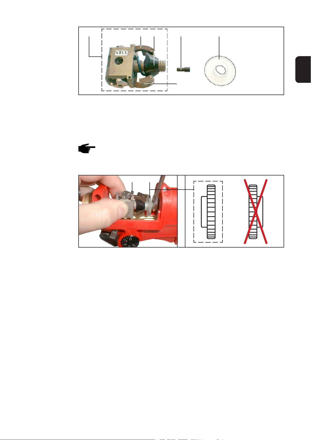
Fit the new
pressure spring
(continued)
(7) (1)(2) (3)(4)
EN
(4)
Fig.40 Placing the taper clamping sleeve onto the pressure spring and tightening the knurled nut
- Align the taper clamping sleeve (3) so that the clamping levers (4) can slide across
the flat zones on the taper clamping sleeve (3)
- Slightly raise the clamping levers (4)
- Press the taper clamping sleeve (3) against the force of the spring, turning the taper
clamping sleeve (3) until it is held in place
NOTE! If the wire infeed nozzle (7) has fallen out, insert it into the drive-head.
- Screw the knurled nut (1) to the drive-head, the right way round (see Fig.41 for
correct position)
(2) (1)
Fig.41 Mounting the drive-head
- Hold the drive-head (2) up against the drive shaft
- Fix the drive-shaft in place with the fork spanner (span 8 mm = .32 in.)
- Screw on the drive-head (2) by hand, finger-tight
- Mount the outlet nozzle (see section “Exchanging wire-guidance nozzles”, subsection “Fit the new wire outlet nozzle”)
- Mount the torch neck (see section “Exchanging the inner liner in the torch neck”,
sub-section “Remount the torch neck on the PT Drive”)
19
Page 62

Feeding in the welding electrode
Safety
Preparing the PT
Drive
WARNING! Work that is not carried out correctly can cause serious injury and
damage. The actions described below may ONLY be carried out by skilled,
Fronius-trained personnel! Observe and follow all safety rules.
WARNING! Risk of injury from electric shock and from welding electrode
emerging at speed from the torch. Before performing any of the actions described
below, unplug the power source from the mains and shift the mains switch to the
“O” position.
NOTE! Before feeder-inching the welding electrode into the PT Drive, define
the PT Drive contact pressure where necessary (see “Defining the contact
pressure on the PT Drive“).
- Remove the cover (27) from the PT
(27)
Drive
Feeder-inching
the welding
electrode
Fig.42 Removing the cover
(1)
(1)
Position (A)
(1)
Position (B)
Fig.43 Disengaging the PT Drive
- Screw the knurled nut (1) into Position (A)
- Straighten approx. 15 cm (5.91 in.) of the first length of wire
- Debur the edges of the cut end of the wire, and round them smoothly
20
Page 63

Feeder-inching
the welding
electrode
(continued)
CAUTION! Danger from welding elctrode emerging at speed. Hold the welding
torch so that it points away from your face and body.
CAUTION! Danger of injury from rotating components. While inching-in the
wire, do NOT touch the inside of the PT Drive; also, make sure that no hair or
clothing can be caught up and pulled into the machine. After the wire has been
inched in, only operate the PT Drive with its cover closed.
Important! Before threading the welding electrode make sure that the correct variant of
the PT-Drive has been selected (see Chapter Push-pull alignment).
- Feed the welding electrode into the 4-roller drive and the PT Drive
NOTE! For a description of feeder-inching the welding electrode into the 4roller drive, please refer to the Operating Instructions manual for your
wirefeeder or for the integral wire-drive of the TPS 2700 power source.
EN
Follow-up jobs
(1)
Fig.44 Engaging the PT Drive
- Screw the knurled nut (1) back into its
original position (B) - see Fig.44.
NOTE! For smooth, troublefree
operation, fix the knurled nut (1)
by screwing it down - finger-tight in Position (B).
- Replace the cover on the PT Drive
Adjusting the contact pressure on the wirefeeder
Adjusting the
contact pressure
on the wirefeeder
Important! The correct contact pressure is given in the configuration table (see the
section headed “Configuration table”).
21
Page 64

Configuration table
Contents of the
configuration
table
Configuration
table
The table shown below includes the following information:
- Filler metal
Material and diameter of the welding wire
- PPU variant
Number of the respective variant of the PT Drive for push-pull alignment
- PT Drive
Colour of the respective pressure spring
Max. possible wirefeed speed in conjunction with PT Drive
- 4-roller drive of the wirefeeder being used
Scale value (“4R”) for the contact pressure on the clamping levers
Groove-shape of the feed rollers
Filler metal PPU variant PT Drive 4-roller drive
Material Wire diameter PT Drive Pressure Wirespeed feed Scale Groove
spring value shape
AlSi5/Al99.5 0,8 mm (.030 in.) 50 blue 15 m/min (591 ipm) 1 H
AlSi5/Al99.5 1,0 mm (.040 in.) 51 blue 18 m/min (709 ipm) 1 H
AlSi5/Al99.5 1,2 mm (.045 in.) 52 blue 22 m/min (867 ipm) 1 H
AlSi5/Al99.5 1,6 mm (1/16 in.) 53 white 22 m/min (867 ipm) 1,5 H
AlMg5 0,8 mm (.030 in.) 50 red 15 m/min (591 ipm) 1 H
AlMg5 1,0 mm (.040 in.) 51 red 18 m/min (709 ipm) 1 H
AlMg5 1,2 mm (.045 in.) 52 red 22 m/min (867 ipm) 1 H
AlMg5 1,6 mm (1/16 in.) 53 blue 22 m/min (867 ipm) 1,5 H
CuSi/Steel/CrNi 1,0 mm (.040 in.) 59 noir 20 m/min (788 ipm) 2-3 H
CuSi/Steel/CrNi 1,2 mm (.045 in.) 60 noir 22 m/min (867 ipm) 2-3 H
22
Page 65

Push-pull alignment
General remarks
Push-pull alignment
The PT Drive must be aligned prior to each initial start-up and after every update of the
wirefeeder software. If no alignment of the PT Drive is carried out, the standard
parameters will be used - which may lead to the welding result being unsatisfactory.
1. Select the “PPU” function in the
second menu level (2nd).
For an overview of the error messages which may occur during push-pull alignment,
please refer to the following section headed “Service codes for push-pull alignment”.
2. Use the adjusting dial (or “Mode”
button on the “Standard” control
panel) to select the relevant variant of
the PT Drive:
- Select the appropriate variant of the PT Drive from the configuration table (see the
section headed “Configuration table”)
3. Press the torch trigger or "Feeder
inching" button once
EN
4. Disengage the drive units of both wirefeeder motors (PT Drive and wirefeeders) the wirefeeder motors must not be under load (push-pull alignment - open circuit)
(1)
Fig.45 Disengaging the PT Drive
To disengage the drive unit of the PT
Drive, proceed as follows:
- Screw the knurled nut (1) in Position
(A) - see Fig.42
Important! The drive unit of the PT Drive
is not properly disengaged until it is
possible to turn the drive-head with ease.
23
Page 66

Push-pull alignment
(continued)
CAUTION! Danger of injury from rotating components. During the push-pull
alignment, do NOT touch the inside of the PT Drive; also, make sure that no
hair or clothing can be caught up and pulled into the machine.
5. Press the torch trigger or the "Feeder
inching" button again.
The wirefeeder motors are aligned
while not under load. During the
alignment operation, the right-hand
display will read “run”.
6. As soon as the alignment operation in the unloaded state - is complete,
the display will read “St2”.
(1)
wirefeeder motors (e.g. welding torch
and wirefeeder) once again - the
wirefeeder motors must be under
load (push-pull alignment - engaged)
To engage the drive unit of the PT Drive,
proceed as follows:
- Screw the knurled nut (1) in Position
(B) - see Fig.42
7. Engage the drive units of both
Fig.46 Engaging the PT Drive
NOTE! For smooth, troublefree operation, fix the knurled nut (1) by screwing it
down - finger-tight - in Position (B).
Important! The drive unit of the PT Drive is not properly engaged until the wire
continues to be fed when you turn the drive-head by hand.
CAUTION! Danger from welding electrode emerging at speed. Hold the
welding torch so that it points away from your face and body.
CAUTION! Danger of injury from rotating components. During the push-pull
alignment, do NOT touch the inside of the PT Drive; also, make sure that no
hair or clothing can be caught up and pulled into the machine. When you have
finished the push-pull alignment, close the cover of the PT Drive.
8. Press the torch trigger or the "Feeder
inching" button once again.
The wirefeeder motors are aligned
while under load. During the alignment operation, the right-hand display
will read “run”.
9. The push-pull alignment is finished
when the previously set values “PPU”
and e.g. “51” reappear on the display.
10. Press the “Store” button twice to exit
from the Set-up menu.
Important! In the following section, you will find a description of the service codes that
can be displayed during the push-pull alignment.
24
Page 67

Service codes for push-pull alignment
WARNING! An electric shock can be fatal. Before opening up the machine:
- shift the mains switch into the "O" position
- unplug the machine from the mains
- put up an easy-to-understand WARNING sign to stop anybody inadvertently switching it back on again
- using a suitable measuring instrument, check to make sure that electrically
charged components (e.g. capacitors) have been discharged
Safety
EN
Error codes
shown when the
drive units are
disengaged
(“open-circuit”
alignment)
Err | Eto
Cause: Incorrect measurement during push-pull alignment.
Remedy: Repeat push-pull alignment
St1 | E 1
Cause: At minimum wirefeed speed, the wirefeeder motor does not deliver any
actual rotational speed value.
Remedy: Repeat the push-pull alignment. If the error message re-appears: Contact
After-Sales Service.
St1 | E 2
Cause: At maximum wirefeed speed, the wirefeeder motor does not deliver any
actual rotational speed value.
Remedy: Repeat the push-pull alignment. If the error message re-appears: Contact
After-Sales Service.
St1 | E 3
Cause: At minimum wirefeed speed, the wirefeeder motor does not deliver any
actual rotational speed value.
Remedy: Repeat the push-pull alignment. If the error message re-appears: Contact
After-Sales Service.
St1 | E 4
Cause: At minimum wirefeed speed, the motor of the push-pull unit does not deliver
any actual rotational speed value.
Remedy: Repeat the push-pull alignment. If the error message re-appears: Contact
After-Sales Service.
St1 | E 5
Cause: At maximum wirefeed speed, the wirefeeder motor does not deliver any
actual rotational speed value.
Remedy: Repeat the push-pull alignment. If the error message re-appears: Contact
After-Sales Service.
St1 | E 6
Cause: At maximum wirefeed speed, the motor of the push-pull unit does not
deliver any actual rotational speed value.
Remedy: Repeat the push-pull alignment. If the error message re-appears: Contact
After-Sales Service.
25
Page 68

Error codes
shown when the
drive units are
engaged (“engaged” alignment)
St1 | E 16
Cause: Push-pull alignment has been interrupted: Quick-stop was activated by
pressing the torch trigger.
Remedy: Repeat push-pull alignment
St2 | E 7
Cause: "Push-pull alignment - open-circuit" has not been carried out
Remedy: Carry out "push-pull alignment - open-circuit"
St2 | E 8
Cause: At minimum wirefeed speed, the motor of the wirefeeder does not deliver
any actual rotational speed value.
Remedy: Repeat the push-pull alignment. If the error message re-appears: Contact
After-Sales Service.
St2 | E 9
Cause: At minimum wirefeed speed, the motor of the push-pull unit does not deliver
any actual rotational speed value.
Remedy: Repeat the push-pull alignment. If the error message re-appears: Contact
After-Sales Service.
St2 | E 10
Cause: At minimum wirefeed speed, the motor current of the wirefeeder motor is
outside the permitted range. Possible causes of this include the wirefeeder
motors not being engaged, and other wirefeed problems.
Remedy: Engage the drive units of both wirefeeder motors, arrange the hosepack in
as straight a line as possible; check the inner liner for kinks or soiling;
check the contact pressure on the 2-roller or 4-roller drive of the push-pull
unit.
Repeat the push-pull alignment. If the error message re-appears: Contact
After-Sales Service.
St2 | E 11
Cause: At minimum wirefeed speed, the motor current of the push-pull unit is
outside the permitted range. Possible causes of this include the wirefeeder
motors not being engaged, and other wirefeed problems.
Remedy: Engage the drive units of both wirefeeder motors, arrange the hosepack in
as straight a line as possible; check the inner liner for kinks or soiling;
check the contact pressure on the 2-roller or 4-roller drive of the push-pull
unit.
Repeat the push-pull alignment. If the error message re-appears: Contact
After-Sales Service.
St2 | E 12
Cause: At maximum wirefeed speed, the motor of the wirefeeder does not deliver
any actual rotational speed value.
Remedy: Repeat the push-pull alignment. If the error message re-appears: Contact
After-Sales Service.
St2 | E 13
Cause: At maximum wirefeed speed, the motor of the push-pull unit does not
deliver any actual rotational speed value.
Remedy: Repeat the push-pull alignment. If the error message re-appears: Contact
After-Sales Service (faulty actual-value pick-up)
26
Page 69

Error codes
shown when the
drive units are
engaged (“engaged alignment”)
(continued)
St2 | E 14
Cause: At maximum wirefeed speed, the motor current of the wirefeeder motor is
outside the permitted range. Possible causes of this include the wirefeeder
motors not being engaged, and other wirefeed problems.
Remedy: Engage the drive units of both wirefeeder motors, arrange the hosepack in
as straight a line as possible; check the inner liner for kinks or soiling;
check the contact pressure on the 2-roller or 4-roller drive of the push-pull
unit.
Repeat the push-pull alignment. If the error message re-appears: Contact
After-Sales Service.
St2 | E 15
Cause: At maximum wirefeed speed, the motor current of the push-pull unit is
outside the permitted range. Possible causes of this include the wirefeeder
motors not being engaged, and other wirefeed problems.
Remedy: Engage the drive units of both wirefeeder motors, arrange the hosepack in
as straight a line as possible; check the inner liner for kinks or soiling;
check the contact pressure on the 2-roller or 4-roller drive of the push-pull
unit.
Repeat the push-pull alignment. If the error message re-appears: Contact
After-Sales Service.
St2 | E 16
EN
Cause: Push-pull alignment has been interrupted: Quick-stop was activated by
pressing the torch trigger.
Remedy: Repeat push-pull alignment
27
Page 70

Troubleshooting
General remarks
PT Drive error
diagnosis
The following section gives you an overview of the possible causes of errors in
connection with the PT Drive, and of steps you can take to remedy the problem. For
detailed information on the causes of, and remedies for, errors in connection with
wirefeeding in general, please refer to the operating instructions of your power source.
No number (“PPU”) available for selecting the push-pull alignment
Cause: The “PMR4000 PullMig installation kit” has not been installed
Remedy: Install the installation kit
The number of the PT Drive (e.g. “PPU | 51”) - for the push-pull alignment - cannot
be selected
Cause: The “FS Drive” software has not been installed on the power source
Remedy: Equip the power source with the “FS Drive” software
The drive-head of the PT Drive does not rotate
Cause: The control plug of the PT Drive is not plugged in
Remedy: Connect up the control plug of the PT Drive to the torch-control
connection point on the wirefeeder or on the TPS 2700 power source
Cause: The connecting cable on the PT Drive is defective
Remedy: Check the connecting cable and have it changed if necessary
Irregular wirefeed speed
Cause: The feed rollers of the PT Drive are not applying sufficient pressure to the
wire
Remedy: Turn the knurled nut completely into Position (B) (Fig.2), and tighten it by
hand to fix it in place
Use a pressure spring that is suitable for the filler metal that is being used
(see the section headed “Configuration table”)
Cause: The wrong contact pressure has been set on the 4-roller drive
Remedy: Set the correct contact pressure on the 4-roller drive
(see the section headed “Configuration table”)
Welding wire is deformed or snaps
Cause: The feed rollers of the PT Drive are applying too much pressure to the wire
Remedy: Use a pressure spring that is suitable for the filler metal that is being used
(see the section headed “Configuration table”)
Cause: The contact pressure on the 4-roller drive is set too high
Remedy: Set the correct contact pressure on the 4-roller drive
(see the section headed “Configuration table”)
Cause: PT Drive turns too fast or too slowly
Remedy: For push-pull alignment, select the right number (e.g. “PPU | 51”) for the
PT Drive (see the section headed “Configuration table”)
28
Page 71

PT Drive error
diagnosis
(continued)
PT Drive overheats
Cause: Inadequate cooling; not enough coolant return-flow to the cooling unit, or
none at all
Remedy: Check whether the PT Drive is completely connected up; check the
cooling unit and vent it if necessary; check the coolant through-flow in the
PT Drive
EN
EFd | xx.x, EFd | 8.1
Cause: Wirefeeder motor is stuck / defective
Remedy: Check the wirefeeder motor and replace it if necessary
EFd | 8.2
Cause: Error in the wirefeed system (overcurrent in the drive of the push-pull unit)
Remedy: Arrange the hosepack in as straight a line as possible; check the inner
liner for kinks or soiling; check the contact pressure on the 2-roller or 4roller drive of the push-pull unit
EFd | 9.1
Cause: External supply voltage: The supply voltage has dropped below the
tolerance range
Remedy: Check the external supply voltage
EFd | 9.2
Cause: External supply voltage: The supply voltage has risen above the tolerance
range
Remedy: Check the external supply voltage
29
Page 72

Care, maintenance and disposal
General remarks
Under normal operating conditions, the PT Drive needs only a minimum of care and
maintenance. However, to ensure continued trouble-free operation of your welding torch
for years to come, there are a few basic points that you should observe:
Regular preventive maintenance of the welding torch is essential for problem-free
operation. The welding torch is subjected to high temperatures and heavy soiling. The
welding torch therefore requires more frequent maintenance than other components in
the welding system.
Important! When removing welding spatter, avoid scoring or scratching the torch. Future
welding spatter may become firmly lodged in score or scratch marks.
- Do NOT bend the torch neck
Every time before
starting to use
the PT Drive
Fig. 47 Do not knock against other objects Fig. 48 Do not clamp
Fig. 49 Do not bend
- Inspect the PT Drive, interconnecting cable and earth connection for any signs of
damage
CAUTION! Danger of scalding from hot coolant fluid. Do not inspect the water
connections until the coolant has been allowed to cool.
- Check that the water connections are watertight
- Check the amount of coolant flowing back into the coolant reservoir in the cooling
unit
Fig. 50 Do not apply compressed air on the torch
connection side
NOTE! If the PT Drive is started up without any coolant, this will almost always
cause a defect in the torch-body and the hosepack. Fronius will not be liable for
any resulting damage, and all warranty claims shall be null and void.
30
Page 73

Every time before
starting to use
the PT Drive
(continued)
Every start-up:
- Check the contact tube
- Replace worn out contact tube
- Remove welding spatter from gas nozzle
- If there is dirt that cannot be removed from around the nozzle join, replace the gas
nozzle
Every time the
wirespool is
changed
* Check spatter guard and insulation for damage
Fig. 50 Removing welding spatter Fig. 51 Checking spatter guard and insulation
- Check inner liners of welding torch hosepack and torch neck
- Clean inner liner of welding torch hosepack as described in „Cleaning the inner
liner“
- Clean the welding torch hosepack as described in „Cleaning the welding torch
hosepack“
- Clean wearing parts before fitting
EN
Cleaning the
inner liner
Remove inner liner as described in „Fitting/replacing the inner liner“
NOTE! There may be dust deposits and blockages in the inner liner. Only clean
the inner liner when dismantled.
- Clean the inner liner with dry reduced compressed air as shown in the illustration.
Fig. 52 Cleaning the inner liner with compressed air
31
Page 74

Cleaning the
welding torch
hosepack
- Take cover (27) off PT drive
(27)
Fig. 53 Removing the cover
(2)
Fig. 54 Removing the drive head
Fig. 55 Cleaning the welding torch hosepack
- Secure drive shaft using flat spanner
(size 8 mm - 0.32 in.)
- Unscrew drive head (2) and remove
NOTE! There may be dust
deposits and blockages in the
welding torch hosepack. When
cleaning the welding torch hosepack, only apply the compressed
air against the wirefeeding
direction.
- Clean the welding torch hosepack on
the drive shaft using dry, reduced
compressed air
After two wirespools have been
used
Disposal
Replace welding torch inner liner as described in „Fitting/replacing the inner liner“
Dispose of in accordance with the applicable national and local regulations.
32
Page 75

Technical data: torch neck
welding torches
gas-cooled
welding torches
water-cooled
AL216 AL236 AL306 AL406
I (Ampère) 10min/40°C 35 % d.c. 180 40 % d.c. 200 40 % d.c. 260 40 % d.c. 350
M21 (EN 439) 60 % d.c. 140 60 % d.c. 160 60 % d.c. 210 60 % d.c. 280
100 % d.c. 100 100 % d.c. 120 100 % d.c. 160 100 % d.c. 220
I (Ampère) 10min/40°C 35 % d.c. 210 40 % d.c. 230 40 % d.c. 300 40 % d.c. 400
C1 (EN 439) 60 % d.c. 160 60 % d.c. 190 60 % d.c. 240 60 % d.c. 320
100 % d.c. 120 100 % d.c. 150 100 % d.c. 190 100 % d.c. 250
[mm (in.)] 0,6-1,0 (.024-.039) 0,6-1,0 (.024-.039) 0,8-1,2 (.032-.047) 1,0-1,6 (.039-.063)
AL2300 AL2400 AL3000 AL4000
I (Ampère) 10min/40°C 40 % d.c. 200 40 % d.c. 200 40 % d.c. 250 40 % d.c. 350
M21 (EN 439) 60 % d.c. 160 60 % d.c. 160 60 % d.c. 200 60 % d.c. 280
100 % d.c. 120 100 % d.c. 120 100 % d.c. 150 100 % d.c. 220
Voltage rating (V-Peak):
- for manually guided torches: 113 V
- for mechanically guided torches: 141 V
The product complies with standard IEC 60974-7.
EN
I (Ampère) 10min/40°C 40 % d.c. 230 40 % d.c. 240 40 % d.c. 300 40 % d.c. 400
C1 (EN 439) 60 % d.c. 190 60 % d.c. 200 60 % d.c. 240 60 % d.c. 320
100 % d.c. 150 100 % d.c. 160 100 % d.c. 190 100 % d.c. 250
[mm (in.)] 0,6-1,0 (.024-.039) 0,6-1,0 (.024-.039) 0,8-1,2 (.032-.047) 1,0-1,6 (.039-.063)
AW252 AW332/335 AW352 AW502 AW652
I (Ampère) 10min/40°C 60 % d.c. 200
M21 (EN 439) 100 % d.c. 220 100 % d.c. 150 100 % d.c. 300 100 % d.c. 400 100 % d.c. 500
I (Ampère) 10min/40°C 60 % d.c. 250
C1 (EN 439) 100 % d.c. 250 100 % d.c. 190 100 % d.c. 350 100 % d.c. 500 100 % d.c. 600
[mm (in.)] 0,6-1,2 (0.2-0.5)0,8-1,2 (0.3-0.5) 0,8-1,2 (0.3-0.5) 1,0-1,6 (0.4-0.6)1,0-2,4 (0.4-1)
AW2500 AW4000 AW5000 AW7000
I (Ampère) 10min/40°C 100 % d.c. 100 % d.c. 100 % d.c. 100 % d.c.
M21 / C1 (EN 439) 220 / 250 350 / 400 400 / 500 550 / 700
[mm (in.)] 0,6-1,2 (.024-.047) 0,8-1,2 (.032-.047) 1,0-1,6 (.039-.063) 1,0-1,6 (.039-.063)
33
Page 76

Technical data: hosepack
welding torches
gas-cooled
welding torches
water-cooled
PT-Drive
I (Ampère) 10min/40°C 40 % d.c. 280
M21 (EN 439) 60 % d.c. 220
100 % d.c. 170
I (Ampère) 10min/40°C 40 % d.c. 330
C1 (EN 439) 60 % d.c. 270
100 % d.c. 210
[m (ft.)] 4,5/8 (14,7/26,2)
Voltage rating (V-Peak):
- for manually guided torches: 113 V
- for mechanically guided torches: 141 V
*) Minimum cooling power in
accordance with standard IEC
60974-2
The product complies with standard IEC 60974-7.
PT-Drive
I (Ampère) 10min/40°C
M21 (EN 439) 100 % d.c. 400
I (Ampère) 10min/40°C
C1 (EN 439) 100 % d.c. 500
[m (ft.)] 4,5/8 (14.7/26.2)
T
P
Q
p
p
[°C (°F)] 50 °C (122 °F)
max
[W]* 1200 / 1800 W
min
[l/min (gal./min)] 1 (.26)
min
[bar (psi.)] 3 bar (43.5 psi.)
min
[bar (psi.)] 5,5 bar (79.7 psi.)
max
34
Page 77

Cher lecteur
Introduction
Nous vous remercions de votre confiance et vous félicitons d’avoir acheté un produit de
qualité supérieure de Fronius. Les instructions suivantes vous aideront à vous familiariser avec le produit. En lisant attentivement les instructions de service suivantes, vous
découvrirez les multiples possibilités de votre produit Fronius. C’est la seule manière
d’exploiter ses avantages de manière optimale.
Prière d’observer également les consignes de sécurité pour garantir une sécurité accrue
lors de l’utilisation du produit. Une utilisation soigneuse du produit contribue à sa longévité et sa fiabilité. Ce sont des conditions essentielles pour obtenir d’excellents résultats.
FR
ud_fr_st_et_00500 01/2012
Page 78

Page 79

Sommaire
PT-Drive ........................................................................................................................................................ 3
Sécurité .................................................................................................................................................... 3
Aperçu des composants de transport du fil .............................................................................................. 3
Réglage de la puissance de soudage ...................................................................................................... 4
Généralités ............................................................................................................................................... 4
Configuration requise ............................................................................................................................... 4
Équipement de base ..................................................................................................................................... 5
Équipement standard de base ................................................................................................................. 5
Outillage compris dans la livraison ................................................................................................................ 5
Outillage ................................................................................................................................................... 5
Remplacement de l’âme guide-fil pour le coude de tuyau ............................................................................ 6
Sécurité .................................................................................................................................................... 6
Outillage requis ........................................................................................................................................ 6
Dévissage du coude du PT-Drive............................................................................................................. 6
Démontage de la buse de gaz et du tube-contact.................................................................................... 6
Positionnement de l’âme guide-fil ............................................................................................................ 7
Mise à longueur de l’âme guide-fil ........................................................................................................... 7
Monter le coude de tuyau sur le PT-Drive ................................................................................................ 8
Montage/remplacement de l’âme guide-fil pour le faisceau de torche en cas de raccord Fronius ............... 9
Sécurité .................................................................................................................................................... 9
Outillage requis ........................................................................................................................................ 9
Démontage du faisceau de torche ........................................................................................................... 9
Démontage de l’âme guide-fil .................................................................................................................. 9
Montage de l’âme guide-fil ..................................................................................................................... 10
FR
Montage/remplacement de l’âme guide-fil en cas de raccord Euroconnector .............................................11
Sécurité ...................................................................................................................................................11
Outillage requis ....................................................................................................................................... 11
Démontage du faisceau de torche ..........................................................................................................11
Démontage de l’âme guide-fil .................................................................................................................11
Montage de l’âme guide-fil ..................................................................................................................... 12
Raccordement/démontage du faisceau de torche ...................................................................................... 13
Sécurité .................................................................................................................................................. 13
Raccordement du PT-Drive.................................................................................................................... 13
Remplacement des âmes guide-fil .............................................................................................................. 14
Sécurité .................................................................................................................................................. 14
Outillage requis ...................................................................................................................................... 14
Dévisser le tuyau coudé du PT-Drive ..................................................................................................... 14
Démontage de la buse de sortie du fil.................................................................................................... 15
Montage de la buse de sortie du fil ........................................................................................................ 15
Démontage de la buse d’entrée du fil..................................................................................................... 15
Montage de la buse d’entrée du fil ......................................................................................................... 16
Monter le coude sur le PT-Drive............................................................................................................. 16
Définir la pression appliquée sur le PT-Drive .............................................................................................. 17
Sécurité .................................................................................................................................................. 17
Ressort de pression ............................................................................................................................... 17
Outillage requis ...................................................................................................................................... 17
Retirer le tuyau coudé du PT-Drive ........................................................................................................ 17
Démontage du ressort de pression existant........................................................................................... 18
Montage d’un nouveau ressort de pression ........................................................................................... 18
Insertion du fil-électrode .............................................................................................................................. 20
Sécurité .................................................................................................................................................. 20
Préparation du PT-Drive ......................................................................................................................... 20
Enfiler le fil-électrode ............................................................................................................................. 20
Ajustage ultérieur ................................................................................................................................... 21
1
Page 80

Réglage de la pression appliquée sur le dévidoir ........................................................................................ 21
Réglage de la pression appliquée sur le dévidoir ................................................................................... 21
Tableau de configuration ............................................................................................................................. 22
Contenus du tableau de configuration.................................................................................................... 22
Tableau de configuration ........................................................................................................................ 22
Réglage PushPull ........................................................................................................................................ 23
Généralités ............................................................................................................................................. 23
Réglage PushPull ................................................................................................................................... 23
Codes de service ajustage PushPull ........................................................................................................... 25
Sécurité .................................................................................................................................................. 25
Codes d’erreur affichés lorsque les unités d’entraînement sont découplées (ajustage à vide).............. 25
Diagnostic des pannes et élimination .......................................................................................................... 28
Généralités ............................................................................................................................................. 28
Diagnostic des erreurs PT-Drive ............................................................................................................ 28
Entretien, maintenance et élimination ......................................................................................................... 30
Généralités ............................................................................................................................................. 30
A chaque mise en service ...................................................................................................................... 30
Après chaque remplacement de la bobine de fil .................................................................................... 31
Nettoyer l’âme de guidage du fil ............................................................................................................. 31
Nettoyer le faisceau de liaison de la torche de soudage ........................................................................ 32
Après avoir utilisé deux bobines de fil .................................................................................................... 32
Élimination des déchets ......................................................................................................................... 32
Caractéristiques techniques: tuyau coudé ................................................................................................. 33
Caractéristiques techniques: faisceau de câbles ........................................................................................ 34
2
Page 81

PT-Drive
Sécurité
Aperçu des
composants de
transport du fil
AVERTISSEMENT ! Les erreurs de manipulation peuvent causer de graves
dommages corporels et matériels. Avant de mettre en service le PT-Drive, vous
devez impérativement avoir lu intégralement et compris les documents suivants :
- le document ci-joint intitulé « Consignes de sécurité »
- le mode d’emploi du PT-Drive
- le mode d’emploi du générateur de soudage, en particulier le chapitre sur
les consignes de sécurité
ATTENTION ! Risque de blessures émanant des pièces rotatives. Ne faire
marcher le PT-Drive que quand le couvercle est fermé.
(5) (3)
(1)(2) (4)
FR
(2) (3)(5)
Fig. 1 Aperçu des principaux composants du PT-Drive
(4)(6)
(1) Ecrou moleté
(2) Tête d’entraînement
(3) Bague conique
(4) Levier de serrage
(7a): 0,8 mm (.030 in.)
(7b): 1,0 mm (.040 in.)
(7c): 1,2 mm (.045 in.)
(7d): 1,6 mm (1/16 in.)
(5) Ressort de pression
(6) Buse de sortie
(7) Buse d’entrée
(1)
3
Page 82

Réglage de la
puissance de
soudage
(29)
Fig. 2 Potentiomètre de réglage en position ‘’9’’
Le potentiomètre de réglage (29) sert à
régler la puissance de soudage
- 0 ..... puissance de soudage minimale
- 9 ..... puissance de soudage maxima-
le
Important ! Les puissances de soudage
minimale et maximale dépendent :
- du générateur de soudage utilisé
- de la matière sélectionnée
Généralités
Configuration
requise
Le PT-Drive est un appareil de transport du fil extrêmement petit et compact pour le
soudage manuel avec des fils de soudage tendres et de longs faisceaux de câbles.
Deux galets de précision disposés en angle de 90° l‘un par rapport à l‘autre sont en
contact avec tout la surface du fil. La transmission de la force sur une grande surface
assure une excellente avance du fil, même en cas de fils d’aluminium ou de CuSi très
tendres et de très longs faisceaux de câbles.
Le PT-Drive se laisse combiner avec les générateurs de soudage suivants :
- TransSynergic 4000 / 5000
- TransPuls Synergic 2700 / 2700 Duo / 2700 TIG / 2700 DuoTIG
- TransPuls Synergic 4000 / 5000
Les générateurs de soudage et dévidoirs-fil doivent au moins être équipés des versions
de logiciel suivantes :
- Générateur de soudage
- Version de logiciel 3.10.22 ou plus élevée
- Dévidoir ou entraînement de fil intégré dans le générateur de soudage TPS 2700
- Version de logiciel 1.70.16 ou plus élevée
Il vous faut en outre les options suivantes pour le générateur de soudage
- Kit de montage ‘’PMR4000 PullMig TS/TPS 2700-5000 (4,100,217)“
- Logiciel ‘’FS Drive (4,061,113)“
Le PT-Drive se prête actuellement aux diamètres de fil suivants :
- 0,8 mm (.030 in.)
- 1,0 mm (.040 in.)
- 1,2 mm (.045 in.)
- 1,6 mm (1/16 in.)
Vous trouverez les informations de réglage détaillées dans le tableau annexé au présent document.
4
Page 83

Équipement de base
Équipement
standard de base
Accessoires fournis avec l‘équipement de base PT-Drive (option) :
Pos. Dénomination Nombre de pièces
(5) Ressort de pression ...............................................................1
(6) Buse de sortie du fil ............................................................... 1
(7) Buse d‘entrée du fil ................................................................ 1
(22) Buse guide-fil du faisceau...................................................... 1
(21) Âme guide-fil ..........................................................................1
Équipement de base pour alliages d‘aluminium AlMg
(6) (5) (7) (22)
(21)
Équipement de base pour alliages d‘aluminium AlSi
(6) (5) (7) (22)
FR
(21)
Équipement de base pour acier et acier inox
(6) (5) (7) (22)
(21)
Outillage compris dans la livraison
Outillage
(B)
Dénomination
(A) Clé à fourche, ouverture 8 mm / 10
(B) Tournevis plat
mm (.32 in. / .39 in.)
6,5 mm (.26 in.)
Fig.2a Outillage compris dans la livraison
(A)
5
Page 84

Remplacement de l’âme guide-fil pour le coude de
tuyau
Sécurité
Outillage requis
AVERTISSEMENT ! Les travaux mal faits peuvent causer de graves dommages
corporels et matériels. Les opérations décrites ci-après ne doivent être effectuées que par des membres du personnel formés par Fronius ! Observer les
consignes de sécurité.
AVERTISSEMENT ! Risque de choc électrique et danger émanant de la sortie
du fil-électrode. Avant d’effectuer les opérations suivantes, débrancher la prise du
générateur de soudage et mettre le commutateur principal en position ‘’O’’.
Pour tube-contact M6 et M8 :
- clé à fourche, ouverture 7 mm (.28
in.)
- ou en alternative : clé pour tubecontact, ouverture 7 mm (.28 in.)
Référence : 42,0410,0570
Pour tube-contact M10 :
- clé à fourche, ouverture 8 mm (.32
in.)
- ou en alternative : clé pour tubecontact, ouverture 8 mm (.32 in.)
Fig.3 Clé à fourche et pince coupante
Référence : 42,0410,0138
Dévissage du
coude du PTDrive
Démontage de la
buse de gaz et du
tube-contact
(29)
Fig. 4 Démontage du coude de tuyau
- Desserrer l’écrou d’accouplement (13) et séparer le coude (14) du PT-Drive
- Détacher la buse de gaz (29) du manchon de fixation (30)
(15)
(14)
(13)(30)
- Dévisser le tube-contact (15)
M6/M8 ... au moyen de la clé à
fourche ou de la clé pour tubecontact, ouverture 7 mm (.28 in.)
M10 ... à l‘aide de la clé à fourche ou
de la clé pour tube-contact, ouverture
8 mm (.32 in.)
Fig. 5 Dévissage du tube-contact
6
Page 85
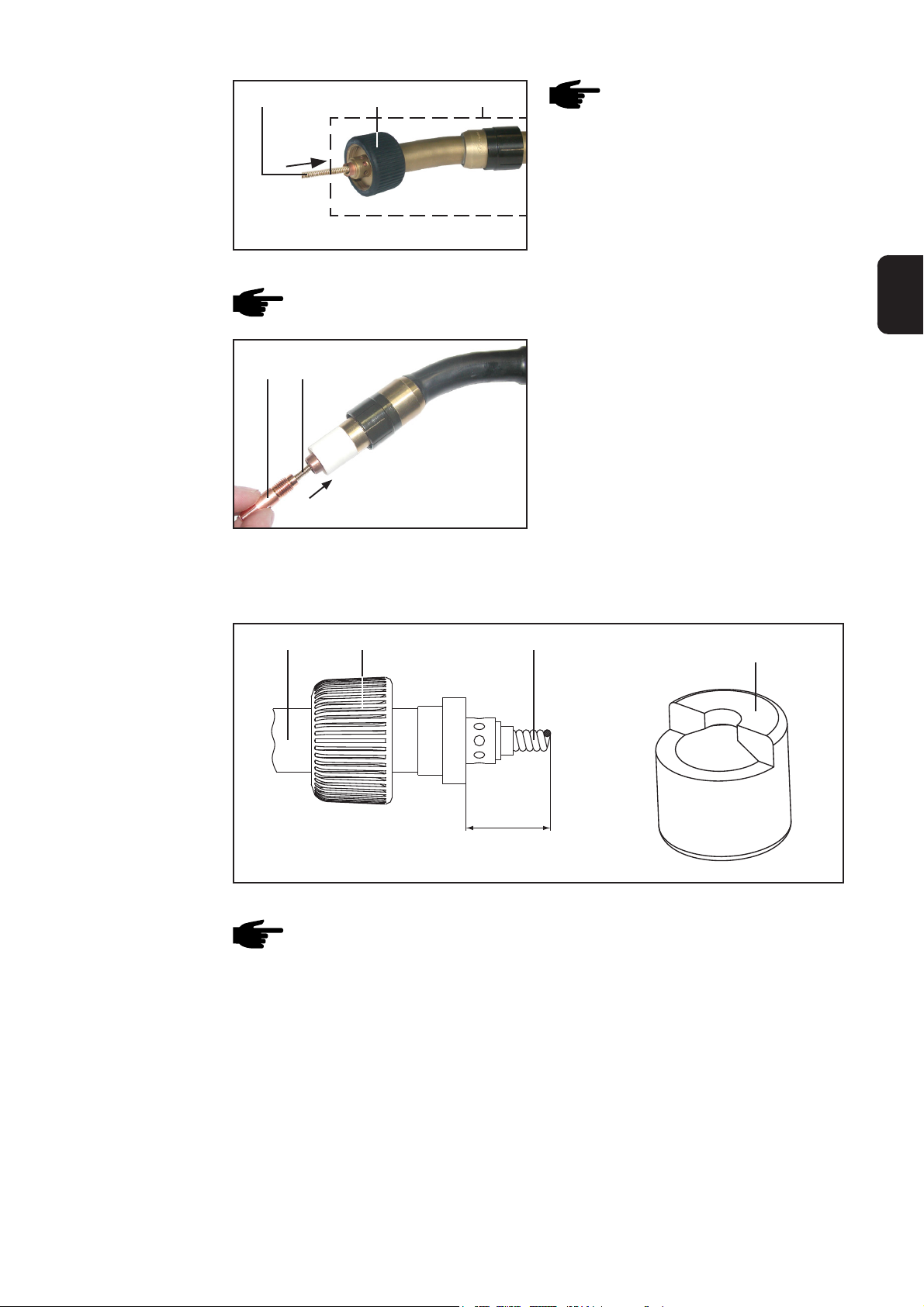
Positionnement
de l’âme guide-fil
(16) (13)
Fig.6 Positionnement de la nouvelle âme guide-fil
(14)
REMARQUE : Danger
d’endommagement en raison
d’impuretés. Avant d’insérer
l’âme guide-fil, purger l’intérieur
du coude à l’air comprimé sec et
réduit
- Insérer prudemment l’âme guide-fil
(16) dans l’écrou d’accouplement (13)
Mise à longueur
de l’âme guide-fil
REMARQUE : Danger d’endommagement du filetage. Nettoyer le tube-contact
et la buse de gaz avant le montage
(15) (16)
Fig. 7 Repousser l’âme guide-fil et visser le tube-
contact
- Insérer l’âme guide-fil (16) en même
temps que le tube-contact (15)
- Visser le tube-contact (15) sur le
corps de la torche
M6/M8 ... au moyen de la clé à
fourche ou de la clé pour tubecontact, ouverture 7 mm (.28 in.)
M10 ... au moyen de la clé à fourche
ou de la clé pour tube-contact, ouverture 8 mm (.32 in.)
- Monter la buse de gaz
(16)(14) (13)
(18)
FR
16,5 mm
(0.65 in.)
Fig. 8 Mesure nécessaire pour la mise à longueur de l’âme guide-fil
REMARQUE : Le tube-contact à l’intérieur du coude (14) doit être monté
solidement.
L’âme guide-fil (16) dépassant l’écrou d’accouplement (13) doit être coupée avec
précision. La figure 9 indique comment procéder avec une gaine de mise à longueur.
7
Page 86

Mise à longueur
de l’âme guide-fil
(suite)
(14)
1.
(16)
(18)
(14)
2.
15,5 mm
(.61 in.)
(16)
(18)
16,5 mm
(.65 in.)
Fig.9 Mise à longueur de l‘âme guide-fil à l‘aide de la gaine
- Glisser la gaine de mise à longueur fournie (18) sur le coude de tuyau (14) jusqu’à
l’arrêt (fig. 9.1)
- Couper l’âme guide-fil à la face avant de la gaine (18) à l’aide d’une pince coupante
(fig. 9.1)
Ensuite, l’âme guide-fil (16) ne doit plus dépasser que d’une spire de l‘orifice de la gaine
(18) (fig. 9.2)
Monter le coude
de tuyau sur le
PT-Drive
Important ! La gaine a une longueur de 15,5 mm (.61 in.). En tenant compte de la
longueur excédentaire d’une spire mentionnée, on obtient la mesure souhaitée
d’environ 16,5 mm (.65 in).
- Retirer la gaine de mise à la longueur (18) du coude de tuyau
Fig.10 Montage du coude de tuyau
(14)
(13)
(16)
REMARQUE : en montant le coude de tuyau sur le PT-Drive, veiller à ce que
l’âme guide-fil (16) glisse sans plier dans l’alésage prévu à cet effet du PTDrive
- Monter le coude de tuyau (14) sur le PT-Drive au moyen de l’écrou d’accouplement
(13).
8
Page 87

Montage/remplacement de l’âme guide-fil pour le
faisceau de torche en cas de raccord Fronius
Sécurité
Outillage requis
Démontage du
faisceau de
torche
AVERTISSEMENT ! Les travaux mal faits peuvent causer de graves dommages
corporels et matériels. Les opérations décrites ci-après ne doivent être effectués
que par des membres du personnel formés par Fronius ! Observer les consignes
de sécurité.
AVERTISSEMENT ! Risque de choc électrique et danger présenté par la sortie
du fil-électrode. Avant d’effectuer les opérations décrites ci-après, débrancher la
prise du générateur de soudage et mettre l’interrupteur principal en position ‘’O’’.
- Clé à fourche
ouverture 10 mm (.39 in.)
- Couteau
Chapitre ‘’Démontage du faisceau de torche’’
- Pince pointue
FR
Démontage de
l’âme guide-fil
Modèle sans buse guide-fil supplémentaire
(19) (20) (21)
Fig.11 Desserrer l’écrou tendeur Fig. 12 Desserrer le tendeur
- Desserrer l‘écrou tendeur du côté du raccord de la torche soudage (19), puis
desserrer le tendeur (20) à l‘aide d‘une clé à fourche d‘une ouverture de 10 mm =
.39 in.
- Retirer l’âme guide-fil existante (21)
Modèle avec buse guide-fil supplémentaire
(19) (22)
(20)(21)
Fig.13 Desserrer l’écrou tendeur
- Démonter l‘écrou tendeur (19) complet avec buse guide-fil (22), puis desserrer le
tendeur (20) à l‘aide d‘une clé à fourche d‘une ouverture de 10 mm = .39 in.
- Retirer l’âme guide-fil existante (21)
9
Fig.14 Desserrer l’écrou tendeur
Page 88

Démontage de
l’âme de guidage
de fil
(suite)
Important ! La buse guide-fil est caractérisée par une couleur en fonction du diamètre
du fil :
- 0,8 mm et .030 in. (gris)
- 1,0 mm et .040 in. (bleu)
- 1,2 mm et .045 in. (rouge)
- 1,6 mm et 1/16 in. (noir)
Montage de l’âme
guide-fil
REMARQUE ! Risque de dommages dus aux salissures. Avant d’insérer l’âme
de guidage du fil, souffler comme suit l’intérieur du coude à l’air comprimé sec
à débit réduit :
(21)
- Insérer précautionneusement une
Fig.15 Insertion de l’âme guide-fil
Exécution sans buse guide-fil supplémentaire
REMARQUE : risque d’endommagement du filetage. Nettoyer l’écrou tendeur
et le tendeur avant le montage.
Important ! Les opérations suivantes ne
(20)
(19)
s‘appliquent qu‘aux âmes guide-fil sans
buse guide-fil du côté de la torche de
soudage.
(21)
- Monter le tendeur (20) du côté du
1 - 2 mm
.04 - .08 in.
Fig.16 Mise à longueur de l’âme guide-fil
- Mettre à longueur l’âme guide-fil (21)
REMARQUE : risque de flambage de l’âme guide-fil. Avant
l’insertion, poser le faisceau à
plat. Dès qu’une résistance se
fait sentir, ne pousser l’âme
guide-fil qu’au niveau du tube
d’entrée de fil.
nouvelle âme guide-fil (21), jusqu’à
ce qu’il ne soit plus possible de la
pousser plus loin.
raccord de la torche de soudage, puis
visser l’écrou tendeur (19) - clé à
fourche, ouverture 10 mm (.39 in.)
sur l’écrou tendeur suivant la fig. 14
Exécution avec buse guide-fil supplémentaire
REMARQUE : risque d’endommagement du filetage. Nettoyer le tendeur et
l’écrou tendeur avant le montage.
(21)(20)
Important ! Les opérations suivantes ne
s‘appliquent qu‘aux âmes guide-fil avec
une buse guide-fil du côté de la torche de
soudage.
- Visser le tendeur (20) sur le côté de
Fig. 17 Mise à longueur l’âme guide-fil à fleur du
tendeur
10
- Couper l’âme guide-fil (21) à fleur du
la torche de soudage - clé à fourche,
ouverture 10 mm (.39 in.)
tendeur (20)
Page 89

Montage de l’âme
guide-fil
(suite)
Fig. 18 Visser l’écrou tendeur
(19) (22)
- Visser l’écrou tendeur (19) avec la
buse guide-fil (22) - clé à fourche,
ouverture 10 mm (.39 in.)
Important ! La buse guide-fil est caractérisée par une couleur en fonction du diamètre
du fil :
- 0,8 mm et .030 in. (gris)
- 1,0 mm et .040 in. (bleu)
- 1,2 mm et .045 in. (rouge)
- 1,6 mm et 1/16 in. (noir)
Montage/remplacement de l’âme guide-fil en cas de
raccord Euroconnector
Sécurité
AVERTISSEMENT ! Les travaux mal faits peuvent causer de graves dommages
corporels et matériels. Les opérations décrites ci-après ne doivent être effectués
que par des membres du personnel formés par Fronius! Observer les consignes
de sécurité.
AVERTISSEMENT ! Risque de choc électrique et danger émanant de la sortie du
fil-électrode. Avant d’effectuer les opérations décrites ci-après, débrancher la
prise du générateur de soudage et mettre l’interrupteur principal en position ‘’O’’.
FR
Outillage requis
Démontage du
faisceau de
torche
Démontage de
l’âme guide-fil
- Clé à fourche
ouverture 12 mm (.47 in.)
- Clé à fourche
ouverture 14 mm (.55 in.)
Chapitre ‘’Démontage du faisceau de torche’’
(23)
Fig.19 Desserrer l’âme guide-fil Fig. 20 Retirer l’âme guide-fil
- Couteau
- Pince pointue
(24)
11
Page 90

Démontage de
l’âme guide-fil
(suite)
- Desserrer complètement l‘écrou d‘accouplement (23) du côté du raccord de la
torche de soudage au moyen d‘une clé à fourche d‘une ouverture de 12 mm (.47
in.)
- Retirer l’âme de guidage de fil existante (24)
Montage de l’âme
guide-fil
REMARQUE ! Risque de dommages dus aux salissures. Avant d’insérer l’âme
de guidage du fil, souffler comme suit l’intérieur du coude à l’air comprimé sec à
débit réduit :
Fig. 21 Insertion de l’âme guide-fil
(25) (23)
Fig.22 Raccord de serrage et écrou
d’accouplement
(24)
REMARQUE : risque de flambage de l’âme guide-fil (24). Poser
le faisceau à plat avant l’insertion.
- Insérer précautionneusement la
nouvelle âme guide-fil (24), jusqu’à ce
qu’il ne soit plus possible de la pousser davantage.
(24)
Important ! Après avoir inséré la nouvelle
âme guide-fil (24), s’assurer que les
composants sont disposés de la manière
suivante :
- lors du montage de la nouvelle âme
guide-fil, disposer le raccord de
serrage (25) et l‘écrou d‘accouplement
(23) avec anneau torique intégré sur la
nouvelle âme guide-fil conformément
à la figure ci-contre et serrer l‘écrou
d‘accouplement avec une clé à fourche de 12 mm d‘ouverture (.47 in.)
REMARQUE : risque d’endommagement du filetage. Nettoyer le raccord de
serrage (25) et l’écrou d’accouplement avant le montage.
(26)
(24)
1 - 2 mm
.04 - .08 in.
Fig. 23 Mise à longueur de l’âme guide-fil
- La buse d’entrée (26) - 42,0001,5421 - est disponible en option
- Serrer la buse d‘entrée (26) sur le raccord de la torche de soudage côté appareil
- au moyen d‘une clé à fourche d‘une ouverture de 14 mm (.55 in.)
- Couper l’âme guide-fil (24) au niveau de la buse d‘entrée du côté du raccord de la
torche de soudage (26), comme représenté en fig. 21.
S’il n’y a pas de buse d’entrée :
- Couper l’âme guide- fil (24) directement au niveau des galets d’entraînement
12
Page 91

Raccordement/démontage du faisceau de torche
Sécurité
Raccordement du
PT-Drive
AVERTISSEMENT ! Les travaux mal faits peuvent causer de graves dommages
corporels et matériels. Les opérations décrites ci-après ne doivent être effectuées que par des membres du personnel formés par Fronius ! Observer les
consignes de sécurité.
(8)
Important ! La figure ci-après montre le
raccordement du PT-Drive au dévidoir VR
4000 (8). Le raccordement aux dévidoirs
ou à l’entraînement de fil intégré de la
source de courant TPS 2700 s’effectue
d’après le même principe.
- Mettre le commutateur principal en
position ‘’O’’
- Insérer le PT-Drive correctement
équipé avec le tube d’entrée en
premier dans le raccord de la torche
de soudage (9)
- Serrer l’écrou d’accouplement pour le
fixer
- Ficher la fiche de commande du PTDrive dans le raccord commande de
la torche (10) et la verrouiller
FR
(10)(9) (12) (11)
Fig. 24 Raccordement du PT-Drive
Important ! Les raccords pour l’arrivée et le retour de l’eau, si existants, peuvent être
connectés librement, le sens de circulation de l’eau dans le PT-Drive étant indifférent.
- Raccorder les flexibles d’eau de refroidissement du PT-Drive aux raccords embrochables de l’arrivée (11) et du retour (12) d’eau
13
Page 92

Remplacement des âmes guide-fil
Sécurité
Outillage requis
Dévisser le tuyau
coudé du PTDrive
AVERTISSEMENT ! Les travaux mal faits peuvent causer de graves dommages
corporels et matériels. Les opérations décrites ci-après ne doivent être effectuées que par des membres du personnel formés par Fronius ! Observer les
consignes de sécurité.
AVERTISSEMENT ! Risque de choc électrique et danger présenté par la sortie
du fil-électrode. Avant d’effectuer les opérations décrites ci-après, débrancher la
prise du générateur de soudage et mettre l’interrupteur principal en position ‘’O’’
- Clé à fourche, ouverture 8 mm (.32
in.)
- Tournevis plat 6,5 mm (.26 in.)
Fig.25 Clé à fourche et tournevis plat
(13)(14)
Fig.26 Retirer le tuyau coudé
- Desserrer l’écrou d’accouplement (13) et séparer le tuyau coudé (14) du PT-Drive
14
Page 93

Démontage de la
buse de sortie du
fil
(6)
(28)
Fig.27 Retirer le couvercle
(27)
Procéder comme suit pour démonter la
buse de sortie :
- retirer le couvercle (27) du PT-Drive
- devisser la buse de sortie du fil (6) au
moyen d’un tournevis plat (6,5 mm .26 in.) à la position (28)
FR
Montage de la
buse de sortie du
fil
(6)
Fig.28 Montage de la buse de sortie
(28)
(27)
Fig.29 Placer le couvercle
- Visser la buse de sortie du fil (6) au
moyen d’un tournevis plat (6,5 mm .26 in.) à la position (28)
- Placer le couvercle (27) sur le PTDrive
Démontage de la
buse d’entrée du
fil
(2)
Fig.30 Démontage de la tête motrice
- Démonter la buse de sortie du fil
(chapitre ‘’Démontage de la buse de
sortie du fil’’)
- Fixer l’arbre moteur au moyen de la
clé à fourche (8 mm - .32 in.)
- Devisser la tête motrice à la main et
la retirer
15
Page 94

Démontage de la
buse d’entrée du
fil
(suite)
(2) (7)
Fig. 31 Retirer la buse d’entrée du fil
- Retirer la buse d’entrée du fil (7) de la tête motrice
Montage de la
buse d’entrée du
fil
Monter le coude
sur le PT-Drive
(2) (1)
- Placer la buse d’entrée du fil (7) dans
la tête motrice (2) (fig. 31)
- Placer la tête motrice (2) sur l’arbre
moteur
- Fixer l’arbre moteur au moyen d’une
clé à fourche (ouverture de clé de 8
mm - .32 in.)
- Visser solidement la tête motrice (2)
Fig.32 Montage de la tête motrice
Monter la tête de sortie du fil (section ‘’Montage de la tête de sortie du fil’’)
(13)(14) (16)
Fig.33 Montage du tuyau coudé
REMARQUE : En montant le coude sur le PT-Drive, veiller à ce que l’âme
guide-fil (16) glisse sans plier dans l’alésage prévu à cet effet du PT-Drive
- Monter le tuyau coudé (14) sur le PT-Drive au moyen de l’écrou d’accouplement
(13)
16
Page 95

Définir la pression appliquée sur le PT-Drive
Sécurité
Ressort de
pression
Outillage requis
AVERTISSEMENT ! Les travaux mal faits peuvent causer de graves dommages
corporels et matériels. Les opérations décrites ci-après ne doivent être effectuées que par des membres du personnel formés par Fronius ! Observer les
consignes de sécurité.
AVERTISSEMENT ! Risque de choc électrique et danger présenté par la sortie
du fil-électrode. Avant d’effectuer les opérations décrites ci-après, débrancher la
prise du générateur de soudage et mettre l’interrupteur principal en position ‘’O’’
La pression appliquée dépend du ressort de pression (5) utilisé (fig. 1). En principe,
quatre ressorts de pression différents sont disponibles pour le PT-Drive
- Ressort de pression blanc / bleu ... pour les alliages AlSi / Al99.5
- Ressort de pression rouge ...pour les alliages AlMg
- Ressort de pression noir ... pour les alliages CuSi3
Le domaine d’application détaillé des ressorts de pression figure dans le tableau de
configuration (voir chapitre ‘’Tableau de configuration’’)
- Clé à fourche
(ouverture de clé de 8 mm - .32 in.)
- Tournevis plat (6,5 mm - .26 in.)
FR
Retirer le tuyau
coudé du PTDrive
Fig.34 Clé à fourche et tournevis plat
(13)(14)
Fig. 35 Retirer le tuyau coudé
- Desserrer l’écrou d’accouplement (13) et retirer le tuyau coudé (14) du PT-Drive
17
Page 96

Démontage du
ressort de pression existant
(2)
Fig.36 Démontage de la tête motrice
- Démonter la buse de sortie (section
‘’Démontage de la buse de sortie du
fil’’)
- Fixer l’arbre moteur au moyen d’une
clé à fourche (ouverture de clé de 8
mm - .32 in.)
- Dévisser la tête motrice à la main et
la retirer
(7) (1)(2) (3)(4)
(4)
Montage d’un
nouveau ressort
de pression
Fig.37 Dévisser l’écrou moleté et retirer la bague conique
REMARQUE : pendant les opérations suivantes, veiller à ce que la buse
d’entrée du fil (7) - illustration - ne se perde pas. Il n’est pas nécessaire de
retirer la buse d’entrée du fil, comme le montre l’illustration.
- Dévisser l’écrou moleté (1) de la tête motrice (2)
- Pousser la bague conique (3) contre la force de pression et la tourner de manière à
pouvoir la retirer (3)
(3)(5)
- Retirer la bague conique (3)
- Retirer le ressort de pression (5)
existant
Fig.38 Retirer le ressort de pression
(3)(5)(4)
Procéder comme suit pour monter le
ressort de pression
- Insérer le ressort de pression (5)
correspondant à la pression requise
- Placer la bague conique (3) sur le
ressort de pression (5)
(4)
Fig.39 Placer un nouveau ressort de pression
18
Page 97

Montage d’un
nouveau ressort
de pression
(suite)
(7) (1)(2) (3)(4)
(4)
Fig.40 Placer la bague conique et visser l’écrou moleté
- Aligner la bague conique (3) de manière à ce que les leviers de pression (4) puissent glisser sur les méplats de la bague conique (3)
- Relever quelque peu les leviers de pression (4)
- Pousser la bague conique (3) contre la force de pression la tourner de manière à
ce qu‘elle (3) soit maintenue après la mise en place
REMARQUE : si la buse d’entrée du fil (7) est tombée, la mettre dans la tête
motrice
- Visser l’écrou moleté (1) dans la bonne position sur la tête motrice (pour la position,
voir fig. 41)
(2) (1)
FR
Fig. 41 Montage de la tête motrice
- Placer la tête motrice (2) sur l’arbre moteur
- Fixer l’arbre moteur au moyen d’une clé à fourche (ouverture de clé de 8 mm - .32
in.)
- Visser solidement la tête motrice (2)
- Monter la buse de sortie (voir chapitre ‘’Remplacement de la buse de guidage de
fil’’, section ‘’Montage de la buse de sortie du fil’’)
- Monter le tuyau coudé (voir chapitre ‘’Remplacement de l’âme guide-fil pour le
tuyau coudé’’, section ‘’Montage du tuyau coudé sur le PT-Drive’’)
19
Page 98

Insertion du fil-électrode
Sécurité
Préparation du
PT-Drive
AVERTISSEMENT ! Les travaux mal faits peuvent causer de graves dommages
corporels et matériels. Les opérations décrites ci-après ne doivent être effectuées que par des membres du personnel formés par Fronius ! Observer les
consignes de sécurité.
AVERTISSEMENT ! Risque de choc électrique et danger présenté par la sortie
du fil-électrode. Avant d’effectuer les opérations décrites ci-après, débrancher la
prise du générateur de soudage et mettre l’interrupteur principal en position ‘’O’’
REMARQUE : avant d’enfiler le fil-électrode dans le PT-Drive, définir la pression appliquée sur le PT-Drive (chapitre ‘’Définition de la pression appliquée sur
le PT-Drive’’)
- Retirer le couvercle du PT-Drive
(27)
Enfiler le filélectrode
Fig. 42 Retirer le couvercle
(1)
(1)
Position (A)
(1)
Position (B)
Fig. 43 Découplage du PT-Drive
- Visser l’écrou moleté (1) en position (A)
- Redresser environ 15 cm (5.91 in.) du premier tronçon de fil
- Ébarber et arrondir les arrêtes de coupe
20
Page 99

Enfiler le filélectrode
(suite )
ATTENTION ! Danger émanant de la sortie du fil-électrode. Tenir la torche
éloignée du visage et du corps.
ATTENTION ! Risque de blessures émanant des pièces rotatives. Ne pas
toucher l’intérieur du PT-Drive pendant qu’on enfile le fil et veiller à ce que les
cheveux ou les vêtements ne soient pas happés. Une fois le fil-électrode enfilé,
ne faire fonctionner le PT-Drive qu’avec le couvercle fermé.
Important ! Avant d‘enfiler le fil-électrode, s‘assurer que le modèle PT-Drive choisi est le
bon (voir chapitre (voir chapitre Réglage PushPull).
- Insérer le fil-électrode dans l’entraînement à 4 galets et dans le PT-Drive
REMARQUE : la manière de procéder pour enfiler le fil-électrode est décrite
dans le mode d’emploi de votre dévidoir-fil ou de l’entraînement de fil intégré
dans la source de courant TPS 2700.
FR
Ajustage ultérieur
(1)
Fig.44 Couplage du PT-Drive
- Visser l’écrou moleté (1) dans la
position d’origine (B) - voir fig. 44
REMARQUE : pour assurer un
fonctionnement correct, fixer
l’écrou moleté (1) en le vissant
solidement en position (B)
- Placer le couvercle sur le PT-Drive
Réglage de la pression appliquée sur le dévidoir
Réglage de la
pression appliquée sur le
dévidoir
Important ! Pour connaître la pression correcte, consulter le tableau de configuration
(voir chapitre ‘’Tableau de configuration’’)
21
Page 100

Tableau de configuration
Contenus du
tableau de configuration
Tableau de
configuration
Le tableau ci-après comprend entre autres les informations suivantes :
- Matière d’apport
Matière et diamètre du fil-électrode
- Variante PPU
Numéro de la variante correspondante du PT-Drive pour le réglage PushPuhll
- PT-Drive
Couleur du ressort de pression correspondant
Vitesse du fil maximum possible en combinaison avec le PT-Drive
- Entraînement à 4 galets du dévidoir utilisé
Valeur graduée (‘’4R’’) pour la pression appliquée sur les leviers de serrage
Forme de la rainure des galets d’entraînement
Matière d’apport Variante PPU PT-Drive Entraînement à 4 galets
Matière Diamètre du fil PT-Drive Ressort Vitesse du fil Valeur Forme de
de pression graduée la rainure
AlSi5/Al99.5 0,8 mm (.030 in.) 50 bleu 15 m/min (591 ipm) 1 H
AlSi5/Al99.5 1,0 mm (.040 in.) 51 bleu 18 m/min (709 ipm) 1 H
AlSi5/Al99.5 1,2 mm (.045 in.) 52 bleu 22 m/min (867 ipm) 1 H
AlSi5/Al99.5 1,6 mm (1/16 in.) 53 blanc 22 m/min (867 ipm) 1,5 H
AlMg5 0,8 mm (.030 in.) 50 rouge 15 m/min (591 ipm) 1 H
AlMg5 1,0 mm (.040 in.) 51 rouge 18 m/min (709 ipm) 1 H
AlMg5 1,2 mm (.045 in.) 52 rouge 22 m/min (867 ipm) 1 H
AlMg5 1,6 mm (1/16 in.) 53 bleu 22 m/min (867 ipm) 1,5 H
CuSi/Steel/CrNi 1,0 mm (.040 in.) 59 noir 20 m/min (788 ipm) 2-3 H
CuSi/Steel/CrNi 1,2 mm (.045 in.) 60 noir 22 m/min (867 ipm) 2-3 H
22
 Loading...